EP3555335B1 - Procédé de fabrication d'objet en fonte à graphite sphéroïdal - Google Patents
Procédé de fabrication d'objet en fonte à graphite sphéroïdal Download PDFInfo
- Publication number
- EP3555335B1 EP3555335B1 EP17823092.6A EP17823092A EP3555335B1 EP 3555335 B1 EP3555335 B1 EP 3555335B1 EP 17823092 A EP17823092 A EP 17823092A EP 3555335 B1 EP3555335 B1 EP 3555335B1
- Authority
- EP
- European Patent Office
- Prior art keywords
- cast iron
- spheroidal graphite
- equal
- graphite cast
- inclusive
- Prior art date
- Legal status (The legal status is an assumption and is not a legal conclusion. Google has not performed a legal analysis and makes no representation as to the accuracy of the status listed.)
- Active
Links
Images



Classifications
-
- C—CHEMISTRY; METALLURGY
- C22—METALLURGY; FERROUS OR NON-FERROUS ALLOYS; TREATMENT OF ALLOYS OR NON-FERROUS METALS
- C22C—ALLOYS
- C22C37/00—Cast-iron alloys
-
- C—CHEMISTRY; METALLURGY
- C22—METALLURGY; FERROUS OR NON-FERROUS ALLOYS; TREATMENT OF ALLOYS OR NON-FERROUS METALS
- C22C—ALLOYS
- C22C37/00—Cast-iron alloys
- C22C37/04—Cast-iron alloys containing spheroidal graphite
-
- B—PERFORMING OPERATIONS; TRANSPORTING
- B22—CASTING; POWDER METALLURGY
- B22D—CASTING OF METALS; CASTING OF OTHER SUBSTANCES BY THE SAME PROCESSES OR DEVICES
- B22D13/00—Centrifugal casting; Casting by using centrifugal force
- B22D13/02—Centrifugal casting; Casting by using centrifugal force of elongated solid or hollow bodies, e.g. pipes, in moulds rotating around their longitudinal axis
- B22D13/023—Centrifugal casting; Casting by using centrifugal force of elongated solid or hollow bodies, e.g. pipes, in moulds rotating around their longitudinal axis the longitudinal axis being horizontal
-
- C—CHEMISTRY; METALLURGY
- C21—METALLURGY OF IRON
- C21C—PROCESSING OF PIG-IRON, e.g. REFINING, MANUFACTURE OF WROUGHT-IRON OR STEEL; TREATMENT IN MOLTEN STATE OF FERROUS ALLOYS
- C21C1/00—Refining of pig-iron; Cast iron
- C21C1/10—Making spheroidal graphite cast-iron
-
- C—CHEMISTRY; METALLURGY
- C21—METALLURGY OF IRON
- C21C—PROCESSING OF PIG-IRON, e.g. REFINING, MANUFACTURE OF WROUGHT-IRON OR STEEL; TREATMENT IN MOLTEN STATE OF FERROUS ALLOYS
- C21C1/00—Refining of pig-iron; Cast iron
- C21C1/10—Making spheroidal graphite cast-iron
- C21C1/105—Nodularising additive agents
-
- C—CHEMISTRY; METALLURGY
- C21—METALLURGY OF IRON
- C21D—MODIFYING THE PHYSICAL STRUCTURE OF FERROUS METALS; GENERAL DEVICES FOR HEAT TREATMENT OF FERROUS OR NON-FERROUS METALS OR ALLOYS; MAKING METAL MALLEABLE, e.g. BY DECARBURISATION OR TEMPERING
- C21D1/00—General methods or devices for heat treatment, e.g. annealing, hardening, quenching or tempering
- C21D1/26—Methods of annealing
- C21D1/30—Stress-relieving
-
- C—CHEMISTRY; METALLURGY
- C21—METALLURGY OF IRON
- C21D—MODIFYING THE PHYSICAL STRUCTURE OF FERROUS METALS; GENERAL DEVICES FOR HEAT TREATMENT OF FERROUS OR NON-FERROUS METALS OR ALLOYS; MAKING METAL MALLEABLE, e.g. BY DECARBURISATION OR TEMPERING
- C21D1/00—General methods or devices for heat treatment, e.g. annealing, hardening, quenching or tempering
- C21D1/84—Controlled slow cooling
-
- C—CHEMISTRY; METALLURGY
- C21—METALLURGY OF IRON
- C21D—MODIFYING THE PHYSICAL STRUCTURE OF FERROUS METALS; GENERAL DEVICES FOR HEAT TREATMENT OF FERROUS OR NON-FERROUS METALS OR ALLOYS; MAKING METAL MALLEABLE, e.g. BY DECARBURISATION OR TEMPERING
- C21D5/00—Heat treatments of cast-iron
-
- C—CHEMISTRY; METALLURGY
- C21—METALLURGY OF IRON
- C21D—MODIFYING THE PHYSICAL STRUCTURE OF FERROUS METALS; GENERAL DEVICES FOR HEAT TREATMENT OF FERROUS OR NON-FERROUS METALS OR ALLOYS; MAKING METAL MALLEABLE, e.g. BY DECARBURISATION OR TEMPERING
- C21D9/00—Heat treatment, e.g. annealing, hardening, quenching or tempering, adapted for particular articles; Furnaces therefor
- C21D9/08—Heat treatment, e.g. annealing, hardening, quenching or tempering, adapted for particular articles; Furnaces therefor for tubular bodies or pipes
-
- C—CHEMISTRY; METALLURGY
- C22—METALLURGY; FERROUS OR NON-FERROUS ALLOYS; TREATMENT OF ALLOYS OR NON-FERROUS METALS
- C22C—ALLOYS
- C22C33/00—Making ferrous alloys
- C22C33/08—Making cast-iron alloys
-
- C—CHEMISTRY; METALLURGY
- C22—METALLURGY; FERROUS OR NON-FERROUS ALLOYS; TREATMENT OF ALLOYS OR NON-FERROUS METALS
- C22C—ALLOYS
- C22C37/00—Cast-iron alloys
- C22C37/06—Cast-iron alloys containing chromium
-
- C—CHEMISTRY; METALLURGY
- C22—METALLURGY; FERROUS OR NON-FERROUS ALLOYS; TREATMENT OF ALLOYS OR NON-FERROUS METALS
- C22C—ALLOYS
- C22C37/00—Cast-iron alloys
- C22C37/06—Cast-iron alloys containing chromium
- C22C37/08—Cast-iron alloys containing chromium with nickel
-
- C—CHEMISTRY; METALLURGY
- C22—METALLURGY; FERROUS OR NON-FERROUS ALLOYS; TREATMENT OF ALLOYS OR NON-FERROUS METALS
- C22C—ALLOYS
- C22C37/00—Cast-iron alloys
- C22C37/10—Cast-iron alloys containing aluminium or silicon
Definitions
- the present invention relates to a method of manufacturing a spheroidal graphite iron object produced in a mould.
- Casting alloys or manufacturing methods are known, for example, from the documents FR 2 139 866 ; US 3,891,432 ; DE 101 01 159 and JP-H-082 69614 , CA838011 and FR759342 .
- the object of the invention is to propose an object, and in particular a pipe element or a road element which is more economical than the known objects and in particular which has optimized mechanical properties and low weight for given dimensions.
- an object of the invention is to increase the mechanical strength of cast iron, in order to make it possible either to reduce the thickness of the pipes compared to current pipes by maintaining the resistance to pressure at a given value, or to achieve a higher pressure resistance than current pipes for the same pipe thickness.
- the object of the invention also applies to other objects made of ductile cast iron with spheroidal graphite than pipes, such as tubular connectors and road parts obtained in a foundry.
- the invention seeks to reduce their weight and/or their wall thicknesses while maintaining a given mechanical strength.
- the subject of the invention is a method of manufacturing an object in spheroidal graphite cast iron manufactured in a mold according to claim 1.
- the present description also relates to a pipe element, such as a pipe or a fitting, or a road element, such as a manhole or rainwater evacuation device, comprising a base body, the base body being obtained by a process as defined above.
- FIG. 1 On the Figure 1 is shown an installation for manufacturing a spheroidal graphite cast iron pipe according to one embodiment of the invention, designated by the general reference 2.
- the installation 2 comprises a feed ladle 4, a pouring device 6, a pouring channel 8, an inoculation device 9, a rotating mold 10, a cooling device 12 and an extraction device 14 .
- Installation 2 is used to manufacture piping elements 15, such as pipes, by centrifugation.
- the pipe element 15 forms an object or a base body 16 of spheroidal graphite cast iron.
- the supply ladle 4 is a crucible made of refractory material containing liquid metal, such as cast iron.
- the pouring device 6 also called “basket”, has a volume corresponding to the quantity of liquid metal necessary to manufacture one or more base bodies 16.
- the pouring device 6 can be tilted in a position for pouring the liquid metal into the channel casting 8.
- the pouring channel 8 conducts the liquid metal from the pouring device 6 to the mold 10. It comprises an inlet 20 located close to the pouring device 6 and an outlet 22 extending into the mold 10.
- the pouring channel 8 is inclined relative to the horizontal so that the outlet 22 is located lower than the inlet 20, thereby allowing the molten iron to flow by gravity.
- the rotary mold 10, also called “shell”, has a shape with symmetry of revolution, in the present example generally cylindrical, of axis X-X, inclined with respect to the horizontal so that it is parallel to the channel of casting 8.
- the mold 10 has an inner surface 24 of shape which is the negative surface of the base body 16, as well as a cylindrical outer surface 26.
- the inner surface 24 is provided with a controlled roughness called “peening”, making it possible to entrain the liquid metal in rotation during its casting in the mold 10.
- the mold 10 comprises a spigot end 28, facing the entrance 20, and a socket end 30, which faces away from the entrance 20 and which is provided with a core (not shown).
- the spigot end 28 forms the spigot end of the base body 16, while the socket end 30 forms the socket end of the base body 16.
- the mold 10 can be rotated around the X-X axis. Furthermore, the mold 10 can be driven in translation along the X-X axis between a casting start position, in which the outlet 22 is opposite the interlocking end end 30, and a casting end position. , wherein outlet 22 faces spigot end 28.
- the cooling device 12 comprises a spraying means which is adapted to spray cooling liquid, for example water, onto the outer surface 26 of the mold 10.
- the extraction device 14 is adapted to extract axially from the mold 10 the basic body blank 16 obtained at the end of the casting of the liquid metal in the mold.
- the pouring 6, cooling 12 and extraction 14 devices, the supply ladle 4 and the pouring channel 8 are known per se and are not described in more detail.
- the mold 10 is for example entirely made of forged steel.
- the installation further comprises a heat treatment furnace 40.
- the manufacture of the object or of the basic body 16 according to the invention by means of the installation 2 is carried out as follows.
- the manufacturing process implemented is a process having the characteristics of the manufacturing process called “DeLavaud”.
- Liquid cast iron is introduced into the supply ladle 4.
- the liquid cast iron in the ladle 4 is such that the object or base body 16 obtained with the manufacturing method according to the invention has the chemical composition defined below , and in particular has the silicon content according to the invention.
- the establishment of the final silicon content of the object or of the base body 16 is made before the casting step in the mold 10, by additions of materials containing silicon, in particular FeSi alloys. These additions are made, for example, in the liquid cast iron bath of electric furnaces or in supply ladles.
- the establishment of the final silicon content of the object or of the base body 16, made before the casting step in the mold 10, is carried out by adding to the cast iron a silicon content equal to that of the object minus the content provided by inoculation and/or spheroidization.
- the increase in the silicon content of the spheroidal graphite cast iron according to the invention must not be obtained by increasing the quantity of silicon-based inoculating agent.
- the silicon content in the cast iron of the object provided by the inoculating agent is between 0.1% and 0.3%.
- Liquid cast iron corresponding to the quantity of cast iron required for the base body 16, is introduced into the pouring device 6 through the supply pocket 4.
- the mold 10 is rotated around the X-X axis and it is brought into its casting start position.
- the liquid iron is poured from the pouring device 6 into the pouring channel 8, flows along it and is poured into the mold 10 at the socket end 30.
- the mold 10 is brought towards its end of casting position while the liquid iron is gradually poured onto the interior surface 24 of the mold and that, before the liquid iron comes into contact with the interior surface 24, the device inoculation agent 9 deposits an inoculation agent, for example a powder based on FeSi, on the inner surface 24 of the mold 10.
- an inoculation agent for example a powder based on FeSi
- the inner surface 24 of the mold 10 is not covered with other materials and is in particular devoid of any temporary thermal insulation or temporary refractory material. as used during the casting process called "Wetspray” (see also below regarding the installation of the Figure 3 ).
- the mold 10 is cooled by the cooling device 12.
- the liquid cast iron in the mold 10 is pressed against the surface 24 by centrifugation, solidifies and forms a blank 161 of the base body 16.
- the blank 161 of the base body 16 is extracted from the mold 10 by the extraction device 14.
- the blank 161 of the base body 16 is subjected to a heat treatment, which will be described in more detail below and, at the end of the heat treatment, the base body 16 is obtained.
- composition of the spheroidal graphite cast iron used for the manufacturing process and therefore the composition of the base body 16 comprises, in% by weight, Carbon (C) at a content less than or equal to 3.65%, and Silicon (Si) at a content of between 3.3% inclusive and 3.7% inclusive.
- the rest of the spheroidal graphite cast iron is Iron (Fe), and other residual elements at levels lower than 0.01%, due to the cast iron production process or to inevitable impurities.
- the carbon equivalent C EQ is equal to 4.5%.
- the silicon (Si) content is preferably between 3.4% inclusive and 3.6% inclusive, and preferably between 3.5% inclusive and 3.6% inclusive, in particular in the case of the use of the process DeLavaud as is the case with the present embodiment.
- this “De Lavaud” manufacturing process comprises a step consisting of pouring liquid cast iron into the mold 10 and allowing the liquid cast iron to solidify, obtaining the draft of the cast iron object; then the blank of the cast iron object is subjected to a heat treatment.
- the molten iron is poured into the mold 10 whose shaped inner surface 24 is devoid of temporary thermal insulation or temporary refractory material deposited on the inner surface 24.
- the blank of the base body is at a temperature generally between 900° C. and 1000° C., and in particular equal to approximately 950° C.
- the blank of the base body is at a temperature generally between 550° C. and 650° C., in particular at a temperature of approximately 600° C., forming the starting temperature of the heat treatment in the oven.
- the blank of the cast iron object is heated for a period of between 2 and 10 minutes during a first heat treatment step ED1, until a graphitization temperature above 800°C and in particular above 900°C, but below 1000°C, is reached.
- This first step ED1 of temperature rise makes it possible to relax the internal stresses present in the cast iron.
- a second heat treatment step ED2 the blank of the cast iron object is maintained at the graphitization temperature which in the present case is equal to approximately 950° C.
- the second heat treatment step ED2 has a duration of between 5 minutes and 30 minutes, and in this case has a duration of 15 minutes.
- the cementite is dissolved and transformed into austenite and graphite.
- a third heat treatment step ED3 is implemented.
- the temperature is lowered, starting from the graphitization temperature, to a ferritization start temperature of between 880° C. and 750° C., in this case equal to approximately 800° C.
- the lowering of temperature during step ED3 is carried out over a period of time comprised between 4 and 7 minutes, preferably less than or equal to 6 minutes.
- a fourth heat treatment step ED4 which is a ferritization step
- the blank of the cast iron object is cooled slowly, that is to say at a cooling rate of less than 40° C./minute , preferably between 20°C/minute and 5°C/minute, within a temperature range between 700°C and 780°C.
- the austenite is transformed into ferrite and graphite.
- a fifth step ED5 the blank of the cast iron object is cooled from the temperature at the end of ferritization to a temperature below 100° C., and in particular to an ambient air temperature of 20° C.
- the spheroidal graphite cast iron thus obtained has a tensile strength Rm greater than 470 MPa and preferably a tensile strength Rm greater than 500 MPa and in particular greater than 530 MPa.
- spheroidal graphite cast iron having a silicon content as defined above and manufactured by the DeLavaud process described above meets this requirement.
- the spheroidal graphite cast iron obtained has an elongation at break greater than or equal to 7% and in particular greater than or equal to 8%, greater than or equal to 9% or greater than or equal to 10%.
- the spheroidal graphite cast iron of the object according to the invention has a resilience E greater than or equal to 9.49 Joules at ambient temperature (20° C.). This is obtained inter alia by the fact that the silicon rate does not exceed 3.7%.
- the resilience E is measured by the “Charpy sheep” shock method.
- the manufactured objects comply with the American standard AWWAC151.
- the resilience E measured according to the “Charpy” method is greater than or equal to 10 Joules or greater than or equal to 11 Joules.
- the spheroidal graphite cast iron of the object according to the invention has a Brinell hardness HB less than or equal to 230 HB.
- the pipe element 15 or the base body 16 has a nominal diameter DN and a wall thickness e.
- the nominal diameter DN is for example less than or equal to 600 mm or less than or equal to 1000 mm or less than or equal to 1600 mm.
- the pipe obtained with the installation of the figure 1 and having undergone the heat treatment as described above with reference to the Fig. 2 has a thickness of approximately 5.3 mm
- a pipe obtained with the classic DeLavaud process and whose cast iron has a silicon content of less than 2.9% has a thickness greater than 6.5 mm.
- Installation 2 comprises a device (not shown) for applying a refractory material. This device is suitable for depositing a layer of a temporary refractory material 50 on the inner surface 24 of the mold 10. The method following the installation 2 of the Figure 3 does not form part of the invention.
- the temporary refractory material 50 is known per se and is for example a mixture of water, bentonite and silica-based refractory product.
- the layer of temporary refractory material 50 reduces the cooling rate of the cast iron cast in the mold 10.
- the temporary refractory material 50 is replaced by a temporary thermal insulation material.
- the manufacturing process using the installation 2 is a manufacturing process of the "Wetspray” type.
- the “Wetspray” process does not form part of the invention. This process is as follows.
- temporary refractory material 50 Prior to pouring liquid iron into mold 10, temporary refractory material 50 is disposed on interior surface 24 and forms a layer of temporary refractory material.
- the next step is to pour the liquid iron over the layer of temporary refractory material
- the blank of the base body 16 or the blank of the cast iron object contains no or very little cementite.
- Spheroidal graphite cast iron has an essentially ferritic matrix with a low pearlite content, in particular less than or equal to 10%, given that the Si content is greater than 3.2%.
- FIG 4 is represented the temperature/time diagram during the heat treatment of the blank of the base body 16 or more generally of a blank of the cast iron object manufactured according to the "Wetspray" process by the installation 2 shown on the picture 3 .
- the blank of the basic body 16 or of the cast iron object undergoes a heat treatment.
- the blank of the basic body or of the object is introduced into a furnace at a temperature input greater than 800°C and, in a first heat treatment step EW1, is cooled at a cooling rate of less than 40°C/minute down to an end-of-ferritization temperature of less than 740°C and preferably between 700°C and 740°C.
- This first step EW1 is a ferritization step during which the austenite is transformed into ferrite and into graphite.
- the blank of the base body or of the cast iron object is cooled from the temperature at the end of ferritization to a temperature below 100° C., and preferably between 20°C and 100°C excluded.
- This cooling takes place in air, that is to say at a rate of between 30° C./min and 70° C./min and preferably between 40° C./min and 60° C./min and in particular at about 50° C./min.
- the air temperature during this cooling is between 10°C and 40°C.
- a relaxation heat treatment intended to relax the internal stresses initially present in the cast iron. This consists first of all in heating the blank of the base body 16 or of the cast iron object from the aforementioned temperature located between 20° C. and 100° C. to a relaxation temperature of between 600° C. and 700° C. °C, then maintaining the blank of the basic body or of the cast iron object at this relaxation temperature for a period of between 10 minutes and 30 minutes.
- a fourth step EW4 the blank of the base body 16 or of the cast iron object is cooled down to ambient temperature (20° C.).
- the nominal diameter DN is for example greater than 600mm.
- Tests carried out show that, for an identical bursting pressure and in the case for example of a DN800 pipe, the pipe obtained with the installation of the picture 3 and which has undergone the heat treatment described above with reference to the Fig. 4 has a thickness of approximately 7.7 mm, whereas a pipe obtained with the conventional Wetspray process and whose cast iron has a silicon content of less than 2.9% has a thickness greater than or equal to 9.4 mm.
- the figure 6 shows the resilience E according to the "Charpy sheep” impact test and demonstrates that objects whose spheroidal graphite cast iron contains between 3.3% and 3.5% silicon and manufactured using the Wetspray process followed by a treatment ("WS Treated") as described above, have a resilience well above 10 Joules, unlike spheroidal graphite cast iron obtained by the Wetspray process without subsequent heat treatment ("raw WS" on the figure 6 ) for which a resilience greater than 9.49 Joules is obtained only for silicon contents less than 3%.
- the figure 7 shows that the objects obtained by the Wetspray process followed by heat treatment (“WS Treated”) and having a silicon content of between 3.4 and 3.5% have an elongation A greater than 15% and in particular between 18% and 22% approximately.
- the pipe member made by the above methods may be a tubular member other than a socket pipe, for example a cylindrical tube fitting.
- the composition of the spheroidal graphite cast iron described above can also be used for the manufacture of a cast iron road element such as a manhole or a rainwater evacuation device, or for the manufacture foundry fittings.
- the method of manufacturing such objects consists in pouring liquid cast iron into a mold and inoculating it simultaneously. Then, after extraction from the mold and cooling to a temperature below 100° C., the blank of the cast iron object is subjected to a thermal relaxation treatment. This consists first of all in heating the blank of the object to a relaxation temperature greater than 400°C and preferably between 600°C and 700°C. Then, the blank of the cast iron object is maintained at this relaxation temperature for a period of between 10 minutes and 30 minutes approximately.
- the object blank is cooled to room temperature.
- the cast iron obtained at the end of this heat treatment makes it possible to reduce the weight of the road element or the foundry fitting compared to the known elements while maintaining a given mechanical resistance, or else, at the same weight, makes it possible to increase the mechanical performance of the road element or the foundry fitting.
- the impact strength of cast iron at room temperature (20° C.) is greater than or equal to 10J or greater than or equal to 11J. Resilience is notably measured by the “Charpy sheep” impact test.
- the spheroidal graphite cast iron object according to the invention therefore makes it possible to obtain pipe elements or roadway elements having low wall thicknesses for a given mechanical strength or improved mechanical performance at similar wall thicknesses. Manufacture and use, in particular transport and handling, are therefore economical.
Landscapes
- Chemical & Material Sciences (AREA)
- Engineering & Computer Science (AREA)
- Materials Engineering (AREA)
- Metallurgy (AREA)
- Organic Chemistry (AREA)
- Mechanical Engineering (AREA)
- Physics & Mathematics (AREA)
- Thermal Sciences (AREA)
- Crystallography & Structural Chemistry (AREA)
- Health & Medical Sciences (AREA)
- Child & Adolescent Psychology (AREA)
- Refinement Of Pig-Iron, Manufacture Of Cast Iron, And Steel Manufacture Other Than In Revolving Furnaces (AREA)
Description
- La présente invention concerne un procédé de fabrication d'un objet en fonte à graphite sphéroïdal fabriqué dans un moule.
- Les tuyaux en fonte ductile actuels ont des propriétés mécaniques qui doivent répondre à des normes, telles que les normes EN545 et EN598.
- Les tuyaux en fonte ductile doivent avoir généralement les caractéristiques suivantes :
- une résistance à la traction supérieure ou égale à 420 MPa et notamment comprise entre 420 MPa et 460 MPa,
- un allongement à la rupture A supérieur ou égal à 10% pour les diamètres nominaux en dessous de ou égaux à 1000 mm et supérieur à 7% pour les diamètres nominaux supérieurs à 1000 mm, et
- une dureté Brinell HB inférieure ou égale à 230.
- Les tuyaux en fonte ductile connus conduisent à une épaisseur de paroi importante et à une consommation importante de matière première afin d'obtenir une résistance à l'écrasement donnée.
- Des alliages de fonte ou des procédés de fabrication sont connus par exemple des documents
FR 2 139 866 US 3,891,432 ;DE 101 01 159 etJP-H-082 69614 CA838011 etFR759342 - Le but de l'invention est de proposer un objet, et notamment un élément de tuyauterie ou un élément de voirie qui soit plus économique que les objets connus et notamment qui ait des propriétés mécaniques optimisées et un faible poids pour des dimensions données.
- En particulier, un but de l'invention est une augmentation de la résistance mécanique de la fonte, afin de permettre soit de réduire l'épaisseur des tuyaux par rapport aux tuyaux actuels en maintenant la résistance à la pression à une valeur donnée, soit d'atteindre une résistance à la pression supérieure à celle des tuyaux actuels pour une épaisseur de tuyau identique.
- Le but de l'invention s'applique également à d'autres objets en fonte ductile à graphite sphéroïdal que des tuyaux, tels que des raccords tubulaires et des pièces de voirie obtenus en fonderie. L'invention cherche à réduire leur poids et/ou leurs épaisseurs de paroi tout en conservant une résistance mécanique donnée.
- A cet effet, l'invention a pour objet un procédé de fabrication d'un objet en fonte à graphite sphéroïdal fabriqué dans un moule selon la revendication 1.
- Selon des modes de réalisation particuliers, l'objet du procédé selon l'invention peut comporter l'une ou plusieurs des caractéristiques suivantes :
- la fonte à graphite sphéroïdal a une résilience (E), notamment mesurée selon l'essai de choc « Charpy », supérieure ou égale à 10 Joules ou supérieure ou égale à 11 Joules à 20°C ;
- la teneur en Silicium (Si) de la fonte à graphite sphéroïdal est comprise entre 3,4% et 3,6% ;
- la teneur en Silicium (Si) de la fonte à graphite sphéroïdal est comprise entre 3,5% et 3,6%;
- l'équivalent carbone CEQ = C (%) + 1/3 Si (%) + 1/3 P (%) de la fonte à graphite sphéroïdal est compris entre 4,3% inclus et 4,6% inclus ou entre 4,4% inclus et 4,6% inclus, et est de préférence compris entre 4,45% inclus et 4,55% inclus et est notamment égal à 4,5% ;
- la fonte à graphite sphéroïdal a une résistance à la traction Rm supérieure à 470MPa, de préférence supérieure à 500MPa et notamment supérieure à 530MPa ;
- la fonte à graphite sphéroïdal a un allongement à la rupture A supérieur ou égal à 7% et notamment supérieur ou égal à 10% ;
- la fonte à graphite sphéroïdal a une dureté Brinell HB inférieure ou égale à 250HB, et notamment inférieure ou égale à 230HB.
- La présente description est également afférente à un élément de tuyauterie, tel qu'un tuyau ou un raccord, ou un élément de voirie, tel qu'un regard de chaussée ou dispositif d'évacuation d'eau pluviales, comprenant un corps de base, le corps de base étant obtenu par un procédé tel que défini ci-dessus.
- Selon des modes de réalisation particuliers, le procédé de fabrication peut comprendre l'une ou plusieurs des caractéristiques suivantes
- avant l'étape de faire couler la fonte liquide dans un moule, on met en œuvre une étape d'établissement de la teneur en Silicium de la fonte, en particulier par l'ajout en four de fusion ou en poche de matériaux contenant du silicium, la teneur en silicium ajoutée durant cette étape correspondant à la teneur en Silicium finale de la fonte à graphite sphéroïdal de l'objet moins la teneur en Silicium apportée éventuellement par des traitements de sphéroïdisation et d'inoculation.
- le traitement thermique comprend l'une ou plusieurs des caractéristiques suivantes :
- la première étape de chauffage de l'ébauche de l'objet est une étape de chauffage jusqu'à atteindre une température de graphitisation supérieure à 900°C ;
- la durée durant laquelle l'ébauche de l'objet en fonte est maintenue à la température de graphitisation lors de la deuxième étape de graphitisation est comprise entre 5 et 18 minutes, et de préférence 15 minutes ;
- la troisième étape (ED3) de refroidissement est une étape de refroidissement jusqu'à 800°C.
- L'invention sera mieux comprise à la lecture de la description qui va suivre, donnée uniquement à titre d'exemple et faite en se référant aux dessins annexés sur lesquels :
- la
figure 1 est une vue schématique d'un mode de réalisation d'une installation de fabrication d'un élément de tuyauterie formant un objet selon l'invention ; - la
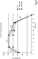
figure 2 est un diagramme temps/température montrant les différentes étapes du traitement thermique de l'ébauche de l'objet selon l'invention fabriquée par l'installation de lafigure 1 ; - la
figure 3 est une vue schématique d'une installation de fabrication d'un élément de tuyauterie; - la
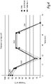
figure 4 est un diagramme temps/température montrant les différentes étapes du traitement thermique de l'ébauche de l'objet fabriquée par l'installation de lafigure 3 ; - la
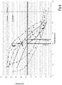
figure 5 montre la résistance à la traction, en fonction de la teneur en silicium, d'exemples de tuyaux en fonte à graphite sphéroïdal fabriqués par les installations selon lesfigures 1 et3 ; - la
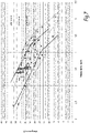
figure 6 est un diagramme montrant l'influence de la teneur en silicium sur la résilience de tuyaux en fonte à graphite sphéroïdal fabriqués par les deux installations selon lesfigures 1 et3 ; et - la
figure 7 montre l'influence de la teneur en silicium sur l'allongement à la rupture de tuyaux en fonte à graphite sphéroïdal fabriqués par les deux installations selon lesfigures 1 et3 . - Sur la
Figure 1 est représentée une installation de fabrication d'un tuyau en fonte à graphite sphéroïdal selon un mode de réalisation de l'invention, désignée par la référence générale 2. - L'installation 2 comprend une poche d'alimentation 4, un dispositif verseur 6, un canal de coulée 8, un dispositif d'inoculation 9, un moule rotatif 10, un dispositif de refroidissement 12 et un dispositif 14 d'extraction.
- L'installation 2 sert à fabriquer par centrifugation des éléments de tuyauterie 15, tels que des tuyaux. L'élément de tuyauterie 15 forme un objet ou un corps de base 16 en fonte à graphite sphéroïdal.
- La poche d'alimentation 4 est un creuset en matière réfractaire contenant du métal liquide, tel que de la fonte.
- Le dispositif verseur 6, également appelé "basket", a un volume correspondant à la quantité de métal liquide nécessaire pour fabriquer un ou plusieurs corps de base 16. Le dispositif verseur 6 peut être incliné dans une position de versement du métal liquide dans le canal de coulée 8.
- Le canal de coulée 8 conduit le métal liquide du dispositif verseur 6 jusqu'au moule 10. Il comprend une entrée 20 située à proximité du dispositif verseur 6 et une sortie 22 s'étendant dans le moule 10. Le canal de coulée 8 est incliné par rapport à l'horizontale de telle sorte que la sortie 22 soit située plus bas que l'entrée 20, permettant ainsi à la fonte liquide de s'écouler par gravité.
- Le moule rotatif 10, également appelé "coquille", a une forme à symétrie de révolution, dans l'exemple présent généralement cylindrique, d'axe X-X, incliné par rapport à l'horizontale de telle sorte qu'il soit parallèle au canal de coulée 8. Dans ce qui suit les expressions "axialement" et "radialement" seront utilisées en référence à cet axe X-X. Le moule 10 a une surface intérieure 24 de forme qui est la surface négative du corps de base 16, ainsi qu'une surface extérieure cylindrique 26. La surface intérieure 24 est pourvue d'une rugosité contrôlée appelée "peening", permettant d'entraîner le métal liquide en rotation lors de sa coulée dans le moule 10.
- Le moule 10 comprend une extrémité bout uni 28, tournée vers l'entrée 20, et une extrémité bout à emboîtement 30, qui est tournée à l'opposé de l'entrée 20 et qui est munie d'un noyau (non représenté). L'extrémité bout uni 28 forme le bout uni du corps de base 16, tandis que l'extrémité bout à emboîtement 30 forme le bout à emboîtement du corps de base 16.
- Le moule 10 peut être entraîné en rotation autour de l'axe X-X. Par ailleurs, le moule 10 peut être entraîné en translation le long de l'axe X-X entre une position de début de coulée, dans laquelle la sortie 22 est en face de l'extrémité bout à emboîtement 30, et une position de fin de coulée, dans laquelle la sortie 22 est en face de l'extrémité bout uni 28.
- Le dispositif de refroidissement 12 comprend un moyen d'arrosage qui est adapté pour projeter du liquide de refroidissement, par exemple de l'eau, sur la surface extérieure 26 du moule 10. Le dispositif d'extraction 14 est adapté pour extraire axialement du moule 10 l'ébauche de corps de base 16 obtenue à l'issue de la coulée du métal liquide dans le moule.
- Les dispositifs verseur 6, de refroidissement 12 et d'extraction 14, la poche d'alimentation 4 ainsi que le canal de coulée 8 sont connus en soi et ne sont pas décrits plus en détail. Le moule 10 est par exemple entièrement en acier forgé.
- L'installation comprend par ailleurs un four de traitement thermique 40.
- La fabrication de l'objet ou du corps de base 16 selon l'invention moyennant l'installation 2 est effectuée comme suit.
- Le procédé de fabrication mise en œuvre est un procédé ayant les caractéristiques du procédé de fabrication appelé « DeLavaud ».
- De la fonte liquide est introduite dans la poche d'alimentation 4. La fonte liquide dans la poche 4 est telle que l'objet ou corps de base 16 obtenu avec le procédé de fabrication selon l'invention a la composition chimique définie ci-après, et a en particulier la teneur en Silicium selon l'invention. L'établissement de la teneur finale en Silicium de l'objet ou du corps de base 16 est faite avant l'étape de coulée dans le moule 10, par des ajouts de matériaux contenant du silicium, notamment des alliages de FeSi. Ces ajouts sont par exemple effectués dans le bain de fonte liquide des fours électriques ou dans des poches d'alimentation. Les apports éventuels en silicium résultant de traitements de sphéroïdisation et/ou d'inoculation utilisant des agents à base de silicium doivent être pris en compte pour déterminer la quantité de silicium à ajouter au métal liquide pour obtenir un objet ou corps de base 16 ayant une teneur en silicium conforme à l'invention.
- Ainsi, l'établissement de la teneur finale en Silicium de l'objet ou du corps de base 16, faite avant l'étape de coulée dans le moule 10, est effectué en ajoutant à la fonte une teneur en Silicium égale à celle de l'objet moins la teneur apportée par l'inoculation et/ou la sphéroïdisation.
- L'augmentation de la teneur en silicium de la fonte à graphite sphéroïdal selon l'invention ne doit pas être obtenue en augmentant la quantité d'agent d'inoculation à base de silicium. Ainsi, dans le cas du procédé DeLavaud, le taux de Silicium dans la fonte de l'objet apporté par l'agent d'inoculation est compris entre 0,1% et 0,3%.
- De la fonte liquide, correspondant à la quantité de fonte nécessaire pour le corps de base 16, est introduite dans le dispositif verseur 6 par la poche d'alimentation 4.
- Le moule 10 est entraîné en rotation autour de l'axe X-X et il est amené dans sa position de début de coulée.
- Ensuite, la fonte liquide est versée du dispositif verseur 6 dans le canal de coulée 8, s'écoule le long de celui-ci et est versée dans le moule 10 à l'extrémité bout à emboîtement 30.
- Successivement, le moule 10 est amené vers sa position de fin de coulée pendant que la fonte liquide est versée progressivement sur la surface intérieure 24 du moule et que, avant que la fonte liquide n'entre en contact avec la surface intérieure 24, le dispositif d'inoculation 9 dépose un agent d'inoculation, par exemple une poudre à base de FeSi, sur la surface intérieure 24 du moule 10. Comme décrit auparavant, lorsque l'agent d'inoculation contient du Silicium, il est nécessaire d'en tenir compte pour l'établissement de la teneur finale en silicium de l'objet ou corps de base 16 moulé.
- Avant et pendant l'étape de la coulée, mis à part l'agent d'inoculation, la surface intérieure 24 du moule 10 n'est pas couverte d'autres matériaux et est en particulier dépourvue de tout isolant thermique temporaire ou matériau réfractaire temporaire tel qu'utilisé lors du procédé de coulée appelé « Wetspray » (voir aussi ci-après concernant l'installation de la
Figure 3 ). - Pendant toute la durée de la coulée, le moule 10 est refroidi par le dispositif de refroidissement 12.
- La fonte liquide se trouvant dans le moule 10 est pressée contre la surface 24 par centrifugation, se solidifie et forme une ébauche 161 du corps de base 16.
- Ensuite, l'ébauche 161 du corps de base 16 est extraite du moule 10 par le dispositif d'extraction 14.
- Puis, l'ébauche 161 du corps de base 16 est soumise à un traitement thermique, qui sera décrit plus en détail ci-dessous et, à l'issue du traitement thermique, on obtient le corps de base 16.
- La composition de la fonte à graphite sphéroïdal utilisée pour le procédé de fabrication et donc la composition du corps de base 16 comprend, en % en poids, du Carbone (C) à une teneur inférieure ou égale à 3,65%, et du Silicium (Si) à une teneur comprise entre 3,3% inclus et 3,7% inclus.
- Optionnellement, la fonte à graphite sphéroïdal comprend, en % en poids, le ou les éléments suivants :
- Phosphore (P) ≤ 0,1%, et/ou
- Manganèse (Mn) ≤ 0,6%, et/ou
- Chrome (Cr) ≤ 0,2%, et/ou
- Titane (Ti) ≤0,15 %, et/ou
- Soufre (S) ≤ 0,05%, et/ou
- Magnésium (Mg) entre 0,005% inclus et 0,07% inclus, et/ou
- Cuivre (Cu) ≤ 0,3%, et/ou
- Nickel (Ni) ≤ 0,4%, et/ou
- Molybdène (Mo) ≤ 0,02%, et/ou
- Aluminium (Al) ≤ 0,02%, et/ou
- Vanadium (V) ≤ 0,04%.
- Le reste de la fonte à graphite sphéroïdal est du Fer (Fe), et d'autres éléments résiduels à des teneurs inférieures à 0,01%, dus au procédé d'élaboration de la fonte ou aux impuretés inévitables.
- La fonte à graphite sphéroïdal a un équivalent carbone CEQ = C (%) + 1/3 Si (%) + 1/3 P (%) inférieur ou égale à 4,75%. Ces % sont également indiqués en % en poids.
- Par ailleurs, la fonte à graphite sphéroïdal peut avoir un équivalent carbone CEQ = C (%)+1/3 Si (%) + 1/3 P (%) inférieur ou égal à 4,7%, de préférence compris entre 4,3% inclus et 4,6% inclus et de préférence compris entre 4,45% inclus et 4,55% inclus. De préférence, l'équivalent carbone CEQ est égal à 4,5%.
- La teneur en silicium (Si) est de préférence comprise entre 3,4% inclus et 3,6% inclus, et de préférence comprise entre 3,5% inclus et 3,6% inclus notamment dans le cas de l'utilisation du procédé DeLavaud comme ceci est le cas du présent mode de réalisation.
- Sur la
figure 2 est représenté le diagramme temps/température lors du traitement thermique de l'ébauche du corps de base 16 ou plus généralement d'une ébauche de l'objet en fonte fabriquée par l'installation 2 de lafigure 1 selon le procédé de fabrication « DeLavaud ». Par la suite les termes « corps de base 16 » et « objet en fonte » seront utilisés de manière synonyme. - Pour mémoire, ce procédé de fabrication « De Lavaud » comprend une étape consistant à faire couler de la fonte liquide dans le moule 10 et à laisser solidifier la fonte liquide en obtenant l'ébauche de l'objet en fonte ; ensuite on fait subir un traitement thermique à l'ébauche de l'objet en fonte. Selon le procédé DeLavaud, on fait couler la fonte liquide dans le moule 10 dont la surface intérieure de forme 24 est dépourvue d'isolant thermique temporaire ou de matière réfractaire temporaire déposé sur la surface intérieure 24.
- Après extraction du moule, l'ébauche du corps de base est à une température généralement comprise entre 900°C et 1000°C, et notamment égale à environ 950°C. A l'entrée du four de traitement thermique 40, l'ébauche du corps de base est à une température généralement comprise entre 550°C et 650°C, notamment à une température d'environ 600°C, formant la température de départ du traitement thermique dans le four.
- Sur la
figure 2 on voit ensuite qu'en partant de cette température de départ, l'ébauche de l'objet en fonte est chauffée pendant une durée comprise entre 2 et 10 minutes lors d'une première étape de traitement thermique ED1, jusqu'à atteindre une température de graphitisation supérieure à 800°C et en particulier supérieure à 900°C, mais inférieure à 1000°C. Cette première étape ED1 de montée en température permet de relaxer les contraintes internes présentes dans la fonte. - Ensuite, dans une deuxième étape de traitement thermique ED2, l'ébauche de l'objet en fonte est maintenue à la température de graphitisation qui dans le cas présent est égale à 950°C environ. La deuxième étape de traitement thermique ED2 a une durée comprise entre 5 minutes et 30 minutes, et a en l'occurrence une durée de 15 minutes. Pendant cette deuxième étape, la cémentite est dissoute et transformée en austénite et en graphite.
- Ensuite, une troisième étape de traitement thermique ED3 est mise en œuvre. Pendant cette étape, la température est baissée, en partant de la température de graphitisation, à une température de début de ferritisation comprise entre 880°C et 750°C, en l'occurrence égale à environ 800°C. L'abaissement de température pendant l'étape ED3 est effectué sur un laps de temps compris entre 4 et 7 minutes, de préférence inférieur ou égal à 6 minutes.
- Puis, pendant une quatrième étape de traitement thermique ED4, qui est une étape de ferritisation, l'ébauche de l'objet en fonte est refroidie lentement, c'est-à-dire à une vitesse de refroidissement inférieure à 40°C/minute, de préférence comprise entre 20°C/minute et 5°C/minute, à l'intérieur d'une plage de températures comprises entre 700°C et 780°C. Pendant cette quatrième étape, l'austénite est transformée en ferrite et en graphite.
- Ensuite, pendant une cinquième étape ED5, l'ébauche de l'objet en fonte est refroidie de la température de fin de ferritisation à une température inférieure à 100°C, et notamment à la température de l'air ambiant de 20°C.
- Ainsi, on obtient l'objet ou le corps de base 16.
- La fonte à graphite sphéroïdal ainsi obtenue a une résistance à la traction Rm supérieure à 470 MPa et de préférence une résistance à la traction Rm supérieure à 500 MPa et notamment supérieure à 530 MPa.
- Comme ceci est visible sur la
figure 5 , la fonte à graphite sphéroïdal ayant une teneur en silicium telle que définie ci-dessus et fabriquée par le procédé DeLavaud décrit ci-dessus respecte cette exigence. - Par ailleurs, la fonte à graphite sphéroïdal obtenue a un allongement à la rupture A supérieur ou égal à 7% et notamment supérieur ou égal à 8%, supérieur ou égal à 9% ou supérieur ou égal à 10%.
- Par ailleurs, la fonte à graphite sphéroïdal de l'objet selon l'invention a une résilience E supérieure ou égale à 9,49 Joules à température ambiante (20°C). Ceci est obtenu entre autres par le fait que le taux de silicium ne dépasse pas 3,7%. La résilience E est mesurée par le procédé de choc « mouton de Charpy ». Ainsi, les objets fabriqués respectent la norme américaine AWWAC151. De préférence, la résilience E mesurée selon le procédé « Charpy » est supérieure ou égale à 10 Joules ou supérieure ou égale à 11 Joules.
- Ceci est montré sur la
figure 6 qui indique que pour des teneurs en silicium entre 3,3% et 3,7%, la résilience E est située au-delà ou est égale à 9,49 Joules pour des tuyaux selon l'invention fabriqués suivant le procédé de centrifugation DeLavaud suivi du traitement thermique décrit ci-dessus. - En outre, la fonte à graphite sphéroïdal de l'objet selon l'invention a une dureté Brinell HB inférieure ou égale à 230 HB.
- En se référant à nouveau à la
figure 1 , l'élément de tuyauterie 15 ou le corps de base 16 a un diamètre nominal DN et une épaisseur de paroi e. Le diamètre nominal DN est par exemple inférieur ou égal à 600 mm ou inférieur ou égal à 1000 mm ou inférieur ou égal à 1600 mm. - Des essais de pression réalisés sur des tuyaux DN400 montrent qu'à épaisseur identique, les tuyaux selon l'invention ont une résistance à la pression de rupture supérieure de 20% à 30% par rapport à des tuyaux en fonte à graphite sphéroïdal présentant une teneur en silicium inférieure à 2.9%.
- De même, pour une pression de rupture identique et dans le cas d'un tuyau DN400, le tuyau obtenu avec l'installation de la
figure 1 et ayant subi le traitement thermique tel que décrit ci-dessus en référence à laFig. 2 a une épaisseur de 5.3 mm environ, alors qu'un tuyau obtenu avec le procédé DeLavaud classique et dont la fonte présente une teneur en Silicium inférieure à 2.9% a une épaisseur supérieure à 6.5 mm. - Sur la
figure 3 est représenté un exemple d'une installation 2 de fabrication. Le procédé suivant l'installation 2 de lafigure 3 ne fait pas partie de l'invention. - L'installation 2 et le procédé de fabrication de l'élément de tuyauterie diffèrent de l'installation et du procédé décrits ci-dessus uniquement par ce qui suit. Les éléments analogues portent les mêmes références.
- L'installation 2 comprend un dispositif (non-représenté) d'application d'un matériau réfractaire. Ce dispositif est adapté pour déposer une couche d'un matériau réfractaire temporaire 50 sur la surface intérieure 24 du moule 10. Le procédé suivant l'installation 2 de la
Figure 3 ne fait pas partie de l'invention. - Le matériau réfractaire temporaire 50 est connu en soi et est par exemple un mélange d'eau, de bentonite et de produit réfractaire à base de silice. La couche de matériau réfractaire temporaire 50 réduit la vitesse de refroidissement de la fonte coulée dans le moule 10. Alternativement, le matériau réfractaire temporaire 50 est remplacé par un matériau d'isolant thermique temporaire.
- Le procédé de fabrication utilisant l'installation 2 est un procédé de fabrication du type « Wetspray ». Le procédé « Wetspray » ne fait pas partie de l'invention. Ce procédé est le suivant.
- Avant de faire couler la fonte liquide dans le moule 10, le matériau réfractaire temporaire 50 est disposé sur la surface intérieure 24 et forme une couche de matériau réfractaire temporaire.
- L'étape suivante consiste à faire couler la fonte liquide sur la couche de matériau réfractaire temporaire
- Grâce à la couche de matériau réfractaire 50, l'ébauche du corps de base 16 ou l'ébauche de l'objet en fonte ne contient pas ou très peu de cémentite. La fonte à graphite sphéroïdal présente une matrice essentiellement ferritique avec une teneur en perlite faible, notamment inférieure ou égale à 10%, étant donné que la teneur en Si est supérieure à 3,2%.
- Sur la
figure 4 est représenté le diagramme température/temps lors du traitement thermique de l'ébauche du corps de base 16 ou plus généralement d'une ébauche de l'objet en fonte fabriquée selon le procédé « Wetspray » par l'installation 2 montré sur lafigure 3 . - Après extraction du moule 10, l'ébauche du corps de base 16 ou de l'objet en fonte subit un traitement thermique, A cet effet, l'ébauche du corps de base ou de l'objet est introduite dans un four à une température d'entrée supérieure à 800°C et, dans une première étape de traitement thermique EW1, est refroidie à une vitesse de refroidissement inférieure à 40°C/minute jusqu'à une température de fin de ferritisation inférieure à 740°C et de préférence comprise entre 700°C et 740°C. Cette première étape EW1 est une étape de ferritisation durant laquelle l'austénite est transformée en ferrite et en graphite.
- Ensuite, lors d'une deuxième étape de traitement thermique EW2, l'ébauche du corps de base ou de l'objet en fonte est refroidie de la température de fin de ferritisation jusqu'à une température inférieure à 100°C, et de préférence comprise entre 20°C et 100°C exclue. Ce refroidissement a lieu à l'air, c'est-à-dire à une vitesse comprise entre 30°C/min et 70°C/min et de préférence comprise entre 40°C/min et 60°C/min et notamment à environ 50°C/min. La température de l'air pendant ce refroidissement est comprise entre 10°C et 40°C.
- Ensuite, dans une troisième étape de traitement thermique EW3, l'ébauche du corps de base ou de l'objet en fonte subit un traitement thermique de relaxation destiné à relaxer les contraintes internes présentes initialement dans la fonte. Celui-ci consiste tout d'abord à chauffer l'ébauche du corps de base 16 ou de l'objet en fonte depuis la température précitée située entre 20°C et 100°C à une température de relaxation comprise entre 600°C et 700°C, puis de maintenir l'ébauche du corps de base ou de l'objet en fonte à cette température de relaxation pendant une durée comprise entre 10 minutes et 30 minutes.
- Ensuite, dans une quatrième étape EW4, l'ébauche du corps de base 16 ou de l'objet en fonte est refroidie jusqu'à température ambiante (20°C).
- Le diamètre nominal DN est par exemple supérieur à 600mm.
- Des essais réalisés montrent que, pour une pression de rupture identique et dans la cas par exemple d'un tuyau DN800, le tuyau obtenu avec l'installation de la
figure 3 et qui a subi le traitement thermique décrit ci-dessus en référence à laFig. 4 a une épaisseur de 7,7 mm environ, alors qu'un tuyau obtenu avec le procédé Wetspray classique et dont la fonte présente une teneur en Silicium inférieure à 2.9% a une épaisseur supérieure ou égale à 9.4 mm. - Sur la
figure 5 on voit que les objets en fonte à graphite sphéroïdal fabriqués selon le procédé Wetspray et comprenant entre 3,3% et 3,5% de silicium ont une résistance à la traction supérieure à 530 MPa. - La
figure 6 montre la résilience E selon le test d'impact « mouton de Charpy » et démontre que les objets dont la fonte à graphite sphéroïdal contient entre 3,3% et 3,5% de silicium et fabriqués selon le procédé Wetspray suivi d'un traitement thermique (« WS Traité») tel que décrit ci-dessus, ont une résilience bien au-delà de 10 Joules, contrairement à la fonte à graphite sphéroïdal obtenue par le procédé Wetspray sans traitement thermique ultérieur (« WS brut » sur lafigure 6 ) pour laquelle une résilience supérieure à 9,49 Joules n'est obtenue que pour des teneurs en silicium inférieures à 3%. - De même, la
figure 7 montre que les objets obtenus par le procédé Wetspray suivi du traitement thermique (« WS Traité ») et ayant une teneur en silicium comprise entre 3,4 et 3,5% ont un allongement A supérieur à 15% et notamment compris entre 18% et 22% environ. - L'élément de tuyauterie fabriqué par les procédés ci-dessus peut être un élément tubulaire autre qu'un tuyau à emboîtement, par exemple un raccord tubulaire cylindrique.
- La composition de la fonte à graphite sphéroïdal décrite ci-dessus peut être également utilisée pour la fabrication d'un élément de voirie en fonte tel qu'un regard de chaussée ou un dispositif d'évacuation d'eaux pluviales, ou encore pour la fabrication de raccords de fonderie. Dans ce cas, le procédé de fabrication de tels objets consiste à couler la fonte liquide dans un moule et à l'inoculer simultanément. Puis, après extraction du moule et refroidissement jusqu'à une température inférieure à 100°C, l'ébauche de l'objet en fonte est soumise à un traitement thermique de relaxation. Celui-ci consiste tout d'abord à chauffer l'ébauche de l'objet à une température de relaxation supérieure à 400°C et de préférence comprise entre 600°C et 700°C. Ensuite, l'ébauche de l'objet en fonte est maintenue à cette température de relaxation pendant une durée comprise entre 10 minutes et 30 minutes environ. Pour finir, l'ébauche de l'objet est refroidie jusqu'à la température ambiante. La fonte obtenue à l'issue de ce traitement thermique permet de réduire le poids de l'élément de voirie ou du raccord de fonderie par rapport aux éléments connus tout en conservant une résistance mécanique donnée, ou bien, à poids identique, permet d'augmenter les performances mécaniques de l'élément de voirie ou du raccord de fonderie.
- D'une manière générale, la résilience de la fonte, à température ambiante (20°C) est supérieure ou égale à 10J ou supérieure ou égale à 11J. La résilience est notamment mesurée par l'essai de choc « mouton de Charpy ».
- L'objet en fonte à graphite sphéroïdal selon l'invention permet donc l'obtention d'éléments de tuyauterie ou d'éléments de voirie ayant des épaisseurs de paroi faibles pour une résistance mécanique donnée ou des performances mécaniques améliorées à épaisseurs de paroi semblables. La fabrication et l'utilisation, notamment le transport et la manipulation, sont donc économiques.
Claims (10)
- Procédé de fabrication d'un objet comprenant les étapes successives suivantesa) on fait couler de la fonte liquide dans un moule (10) ayant une surface de forme (24),b) on laisse solidifier la fonte liquide en obtenant une ébauche de l'objet,c) on fait subir un traitement thermique à l'ébauche de l'objet, notamment un traitement de relaxation en obtenant l'objet en fonte (16), dans lequell'objet (16) est en fonte à graphite sphéroïdal
la fonte à graphite sphéroïdal comprenant, en % en poids, les éléments suivants :- Carbone (C) inférieur ou égal à 3,65%,- Silicium (Si) entre 3,3% et 3,7%,Optionnellement :- Phosphore (P) ≤ 0,1%, et/ou- Manganèse (Mn) ≤ 0,6%, et/ou- Chrome (Cr) ≤ 0,2%, et/ou- Titane (Ti) ≤0,15 %, et/ou- Soufre (S) ≤ 0,05%, et/ou- Magnésium (Mg) entre 0,005% inclus et 0,07% inclus, et/ou- Cuivre (Cu) ≤ 0,3%, et/ou- Nickel (Ni) ≤ 0,4%, et/ou- Molybdène (Mo) ≤ 0,02%, et/ou- Aluminium (Al) ≤ 0,02%, et/ou- Vanadium (V) ≤ 0,04%,le reste étant du Fer (Fe), et des éléments résiduels inévitables à des teneurs inférieures à 0,01 %, dans lequella fonte à graphite sphéroïdal a un équivalent carbone CEQ = C (%) + 1/3 Si (%) + 1/3 P (%) inférieur ou égal à 4,75% et dans lequella fonte à graphite sphéroïdal a une résilience (E) supérieure ou égale à 9,49 J à 20°C, mesurée suivant AWWA C151, procédé dans lequella surface de forme (24) est dépourvue d'isolant thermique temporaire ou de matériau réfractaire temporaire (50) lorsqu'on fait couler la fonte liquide dans le moule (10), et dans lequelle traitement thermique comprend- une première étape (ED1) de chauffage de l'ébauche de l'objet pendant une durée comprise entre 2 et 10 minutes jusqu'à atteindre une température de graphitisation supérieure à 800°C, mais inférieure à 1000°C, cette première étape relaxant les contraintes internes présentes initialement dans la fonte,- une deuxième étape (ED2) de graphitisation durant laquelle l'ébauche de l'objet en fonte est maintenue à la température de graphitisation pendant une durée comprise entre 5 et 30 minutes,- une troisième étape (ED3) de refroidissement jusqu'à une température comprise entre 880°C et 750°C, d'une durée inférieure à 7 minutes, et- une quatrième étape (ED4) de ferritisation durant laquelle l'ébauche de l'objet en fonte est refroidie lentement, à une vitesse inférieure à 40°C/minute, à l'intérieur d'une plage de températures comprises entre 700°C et 780°C. - Procédé selon la revendication 1, dans lequel la fonte à graphite sphéroïdal a une résilience (E), notamment mesurée selon l'essai de choc « Charpy », supérieure ou égale à 10 Joules ou supérieure ou égale à 11 Joules à 20°C.
- Procédé selon la revendication 1 ou 2, dans lequel la teneur en Silicium (Si) de la fonte à graphite sphéroïdal est comprise entre 3,4% et 3,6%.
- Procédé selon l'une quelconque des revendications précédentes, dans lequel la teneur en Silicium (Si) de la fonte à graphite sphéroïdal est comprise entre 3,5% et 3,6%.
- Procédé selon l'une quelconque des revendications 1 à 4, dans lequel l'équivalent carbone CEQ = C (%) + 1/3 Si (%) + 1/3 P (%) de la fonte à graphite sphéroïdal est compris entre 4,3% inclus et 4,6% inclus ou entre 4,4% inclus et 4,6% inclus, et est de préférence compris entre 4,45% inclus et 4,55% inclus et est notamment égal à 4,5%.
- Procédé selon l'une quelconque des revendications précédentes, dans lequel la fonte à graphite sphéroïdal a une résistance à la traction Rm supérieure à 470MPa, de préférence supérieure à 500MPa et notamment supérieure à 530MPa.
- Procédé selon l'une quelconque des revendications précédentes, dans lequel la fonte à graphite sphéroïdal a un allongement à la rupture A supérieur ou égal à 7% et notamment supérieur ou égal à 10%.
- Procédé selon l'une quelconque des revendications précédentes, dans lequel la fonte à graphite sphéroïdal a une dureté Brinell HB inférieure ou égale à 250HB, et notamment inférieure ou égale à 230HB.
- Procédé de fabrication selon l'une des revendications 1 à 8, dans lequel, avant l'étape de faire couler la fonte liquide dans un moule, on met en œuvre :
une étape d'établissement de la teneur en Silicium de la fonte, en particulier par l'ajout en four de fusion ou en poche de matériaux contenant du silicium, la teneur en silicium ajoutée durant cette étape correspondant à la teneur en Silicium finale de la fonte à graphite sphéroïdal de l'objet moins la teneur en Silicium apportée éventuellement par des traitements de sphéroïdisation et d'inoculation. - Procédé de fabrication selon l'une des revendications 1 à 9, dans lequel le traitement thermique comprend l'une ou plusieurs des caractéristiques suivantes :- la première étape (ED1) de chauffage est une étape de chauffage jusqu'à atteindre une température de graphitisation supérieure à 900°C ;- la durée durant laquelle l'ébauche de l'objet en fonte est maintenue à la température de graphitisation lors de la deuxième étape (ED2) de graphitisation est comprise entre 5 et 18 minutes, et de préférence 15 minutes ;- la troisième étape (ED3) de refroidissement est une étape de refroidissement jusqu'à 800°C.
Priority Applications (1)
| Application Number | Priority Date | Filing Date | Title |
|---|---|---|---|
| EP22162181.6A EP4050116A1 (fr) | 2016-12-19 | 2017-12-18 | Procédé de fabrication d'un objet en fonte à graphite sphéroïdal, et élément correspondant |
Applications Claiming Priority (2)
| Application Number | Priority Date | Filing Date | Title |
|---|---|---|---|
| FR1662781A FR3060607B1 (fr) | 2016-12-19 | 2016-12-19 | Objet en fonte a graphite spheroidal, element et procede de fabrication correspondants |
| PCT/EP2017/083378 WO2018114845A1 (fr) | 2016-12-19 | 2017-12-18 | Objet en fonte à graphite sphéroïdal, élément et procédé de fabrication correspondants |
Related Child Applications (2)
| Application Number | Title | Priority Date | Filing Date |
|---|---|---|---|
| EP22162181.6A Division EP4050116A1 (fr) | 2016-12-19 | 2017-12-18 | Procédé de fabrication d'un objet en fonte à graphite sphéroïdal, et élément correspondant |
| EP22162181.6A Division-Into EP4050116A1 (fr) | 2016-12-19 | 2017-12-18 | Procédé de fabrication d'un objet en fonte à graphite sphéroïdal, et élément correspondant |
Publications (2)
| Publication Number | Publication Date |
|---|---|
| EP3555335A1 EP3555335A1 (fr) | 2019-10-23 |
| EP3555335B1 true EP3555335B1 (fr) | 2022-04-27 |
Family
ID=58609511
Family Applications (2)
| Application Number | Title | Priority Date | Filing Date |
|---|---|---|---|
| EP22162181.6A Pending EP4050116A1 (fr) | 2016-12-19 | 2017-12-18 | Procédé de fabrication d'un objet en fonte à graphite sphéroïdal, et élément correspondant |
| EP17823092.6A Active EP3555335B1 (fr) | 2016-12-19 | 2017-12-18 | Procédé de fabrication d'objet en fonte à graphite sphéroïdal |
Family Applications Before (1)
| Application Number | Title | Priority Date | Filing Date |
|---|---|---|---|
| EP22162181.6A Pending EP4050116A1 (fr) | 2016-12-19 | 2017-12-18 | Procédé de fabrication d'un objet en fonte à graphite sphéroïdal, et élément correspondant |
Country Status (5)
| Country | Link |
|---|---|
| EP (2) | EP4050116A1 (fr) |
| CN (2) | CN114774767B (fr) |
| ES (1) | ES2914548T3 (fr) |
| FR (1) | FR3060607B1 (fr) |
| WO (1) | WO2018114845A1 (fr) |
Families Citing this family (8)
| Publication number | Priority date | Publication date | Assignee | Title |
|---|---|---|---|---|
| CA3095046A1 (fr) | 2018-03-29 | 2019-10-03 | Oerlikon Metco (Us) Inc. | Alliages ferreux a teneur reduite en carbures |
| EP3870727A1 (fr) | 2018-10-26 | 2021-09-01 | Oerlikon Metco (US) Inc. | Alliages à base de nickel résistants à la corrosion et à l'usure |
| CN113631750A (zh) | 2019-03-28 | 2021-11-09 | 欧瑞康美科(美国)公司 | 用于涂布发动机气缸孔的热喷涂铁基合金 |
| CA3136967A1 (fr) | 2019-05-03 | 2020-11-12 | Oerlikon Metco (Us) Inc. | Charge d'alimentation pulverulente destinee au soudage en vrac resistant a l'usure, concue pour optimiser la facilite de production |
| KR102870036B1 (ko) | 2019-07-09 | 2025-10-13 | 오를리콘 메트코 (유에스) 아이엔씨. | 내마모성 및 내부식성을 위해 설계된 철 기반 합금 |
| FR3099716B1 (fr) * | 2019-08-08 | 2021-08-27 | Saint Gobain Pont A Mousson | Procédé de fabrication d’un élément tubulaire |
| RU2733940C1 (ru) * | 2020-03-02 | 2020-10-08 | Денис Александрович Габец | Чугун |
| FR3141698B1 (fr) | 2022-11-09 | 2024-11-08 | Saint Gobain Pam Batiment | Objet tubulaire en fonte à graphite lamellaire, élément de tuyauterie et procédé de fabrication correspondants |
Family Cites Families (16)
| Publication number | Priority date | Publication date | Assignee | Title |
|---|---|---|---|---|
| CA838011A (en) * | 1970-03-31 | United States Pipe And Foundry Company | Process for casting ductile iron | |
| FR759342A (fr) * | 1932-08-20 | 1934-02-01 | Internat Delavaud Mfg Corp Ltd | Tuyaux en fonte et procédé pour les fabriquer |
| AT275763B (de) * | 1966-03-03 | 1969-11-10 | United States Pipe Foundry | Verfahren zum Gießen duktiler Gußstücke aus Eisen |
| US3415307A (en) * | 1966-03-03 | 1968-12-10 | United States Pipe Foundry | Process for casting ductile iron |
| PL74403B1 (fr) | 1971-06-03 | 1974-10-31 | ||
| JPS543129B2 (fr) | 1973-01-24 | 1979-02-19 | ||
| FR2522291A1 (fr) * | 1982-03-01 | 1983-09-02 | Pont A Mousson | Tube centrifuge en fonte a graphite spheroidal et son procede de fabrication |
| US4475956A (en) * | 1983-01-24 | 1984-10-09 | Ford Motor Company | Method of making high strength ferritic ductile iron parts |
| US5082507A (en) * | 1990-10-26 | 1992-01-21 | Curry Gregory T | Austempered ductile iron gear and method of making it |
| JPH08269614A (ja) | 1995-03-31 | 1996-10-15 | Kubota Corp | ダクタイル鋳鉄管 |
| DE10101159C2 (de) | 2001-01-12 | 2003-05-15 | Siempelkamp Gmbh & Co | Gusswerkstoff mit ferritischem Gefüge und Kugelgraphit, insbesondere ferritisches Gusseisen |
| EP1566454A1 (fr) * | 2004-02-10 | 2005-08-24 | Magna Drivetrain AG & Co KG | Procédé de fabrication de produits en fonte nodulaire et produits obtenus |
| CN101698921B (zh) * | 2009-09-07 | 2011-09-07 | 芜湖市金贸流体科技股份有限公司 | 一种耐磨球墨铸铁的制备方法 |
| KR101294671B1 (ko) * | 2011-11-14 | 2013-08-09 | 엘지전자 주식회사 | 구상흑연주철 및 그를 이용한 로터리 압축기용 베인의 제조방법 |
| CN104775067A (zh) * | 2015-04-01 | 2015-07-15 | 北京纵横机电技术开发公司 | 一种轨道车辆制动盘用合金球墨铸铁 |
| CN105506441B (zh) * | 2015-12-28 | 2017-09-29 | 中车齐齐哈尔车辆有限公司 | 球墨铸铁材料、包含其的组合物和承载鞍及球墨铸铁的制作方法 |
-
2016
- 2016-12-19 FR FR1662781A patent/FR3060607B1/fr active Active
-
2017
- 2017-12-18 EP EP22162181.6A patent/EP4050116A1/fr active Pending
- 2017-12-18 CN CN202210254718.8A patent/CN114774767B/zh active Active
- 2017-12-18 WO PCT/EP2017/083378 patent/WO2018114845A1/fr not_active Ceased
- 2017-12-18 ES ES17823092T patent/ES2914548T3/es active Active
- 2017-12-18 CN CN201780078472.0A patent/CN110268082B/zh active Active
- 2017-12-18 EP EP17823092.6A patent/EP3555335B1/fr active Active
Also Published As
| Publication number | Publication date |
|---|---|
| FR3060607B1 (fr) | 2021-09-10 |
| CN114774767A (zh) | 2022-07-22 |
| CN110268082B (zh) | 2022-04-19 |
| EP3555335A1 (fr) | 2019-10-23 |
| EP4050116A1 (fr) | 2022-08-31 |
| ES2914548T3 (es) | 2022-06-13 |
| WO2018114845A1 (fr) | 2018-06-28 |
| CN110268082A (zh) | 2019-09-20 |
| FR3060607A1 (fr) | 2018-06-22 |
| CN114774767B (zh) | 2023-09-15 |
Similar Documents
| Publication | Publication Date | Title |
|---|---|---|
| EP4050116A1 (fr) | Procédé de fabrication d'un objet en fonte à graphite sphéroïdal, et élément correspondant | |
| BE896059A (fr) | Tube centrifuge en fonte a graphite spheroidal et son procede de fabrication | |
| CA1106134A (fr) | Procede de coulee de metal | |
| EP1504132A1 (fr) | Procede d elaboration et de mise en forme de pieces en fonte a graphite spheroidal a caracteristiques mecaniques elevees | |
| EP1063033B1 (fr) | Procédé de fabrication d'une pièce métallique, telle qu'une partie de roue destinée au roulage d'un véhicule, et une telle roue | |
| CN106636879A (zh) | 一种球墨铸铁轧辊辊身及其制备方法 | |
| EP1323837B1 (fr) | Procédé de réalisation d'un produit sidérurgique en acier au carbone, notamment destiné à la galvanisation. | |
| EP4616010A1 (fr) | Objet tubulaire en fonte à graphite lamellaire, élément de tuyauterie et procédé de fabrication correspondants | |
| CN102191422A (zh) | 一种Fe2B块体/钢铁基复合材料制备方法 | |
| FR2682312A1 (fr) | Procede d'obtention de canaux de petite taille et de tres petite taille dans des articles coules a modele perdu. | |
| FR2486100A1 (fr) | Pieces massives en fonte a graphite spheroidal | |
| CN114101619B (zh) | 一种球墨铸管的离心铸造工艺 | |
| WO2019122635A1 (fr) | Procédé de traitement thermique d'une pièce en acier maraging | |
| CN104889400B (zh) | 粉末冶金耐磨耐蚀合金管材 | |
| HK40121022A (zh) | 片状石墨铸铁管状物体、相应的管道组件和相应的制造方法 | |
| EP1704948B1 (fr) | Pièce métallique résistante à l'usure de forme tubulaire, et procédé de fabrication par coulée d'une telle pièce. | |
| FR3099716A1 (fr) | Procédé de fabrication d’un élément tubulaire | |
| BE863704A (fr) | Procede de fabrication de frettes en alliage de fer et appareillage destine a realiser le procede | |
| CN105642844A (zh) | 一种2205双相不锈钢锭的铸造方法 | |
| FR2868346A1 (fr) | Moule pour la coulee d'un metal liquide et procede correspondant | |
| BE690049A (fr) | ||
| FR2918908A1 (fr) | Procede de fabrication d'une piece en fonte bainitique | |
| BE735339A (fr) | ||
| BE527528A (fr) | ||
| BE428846A (fr) |
Legal Events
| Date | Code | Title | Description |
|---|---|---|---|
| STAA | Information on the status of an ep patent application or granted ep patent |
Free format text: STATUS: UNKNOWN |
|
| STAA | Information on the status of an ep patent application or granted ep patent |
Free format text: STATUS: THE INTERNATIONAL PUBLICATION HAS BEEN MADE |
|
| PUAI | Public reference made under article 153(3) epc to a published international application that has entered the european phase |
Free format text: ORIGINAL CODE: 0009012 |
|
| STAA | Information on the status of an ep patent application or granted ep patent |
Free format text: STATUS: REQUEST FOR EXAMINATION WAS MADE |
|
| 17P | Request for examination filed |
Effective date: 20190619 |
|
| AK | Designated contracting states |
Kind code of ref document: A1 Designated state(s): AL AT BE BG CH CY CZ DE DK EE ES FI FR GB GR HR HU IE IS IT LI LT LU LV MC MK MT NL NO PL PT RO RS SE SI SK SM TR |
|
| AX | Request for extension of the european patent |
Extension state: BA ME |
|
| DAV | Request for validation of the european patent (deleted) | ||
| DAX | Request for extension of the european patent (deleted) | ||
| STAA | Information on the status of an ep patent application or granted ep patent |
Free format text: STATUS: EXAMINATION IS IN PROGRESS |
|
| 17Q | First examination report despatched |
Effective date: 20200622 |
|
| REG | Reference to a national code |
Ref country code: DE Ref legal event code: R079 Ref document number: 602017056638 Country of ref document: DE Free format text: PREVIOUS MAIN CLASS: C22C0037000000 Ipc: C21D0001300000 |
|
| RIC1 | Information provided on ipc code assigned before grant |
Ipc: C22C 37/00 20060101ALI20210817BHEP Ipc: C22C 37/04 20060101ALI20210817BHEP Ipc: C22C 37/06 20060101ALI20210817BHEP Ipc: C22C 37/10 20060101ALI20210817BHEP Ipc: C21D 9/08 20060101ALI20210817BHEP Ipc: C21D 5/00 20060101ALI20210817BHEP Ipc: B22D 13/02 20060101ALI20210817BHEP Ipc: C21C 1/10 20060101ALI20210817BHEP Ipc: C21D 1/30 20060101AFI20210817BHEP |
|
| GRAP | Despatch of communication of intention to grant a patent |
Free format text: ORIGINAL CODE: EPIDOSNIGR1 |
|
| STAA | Information on the status of an ep patent application or granted ep patent |
Free format text: STATUS: GRANT OF PATENT IS INTENDED |
|
| INTG | Intention to grant announced |
Effective date: 20211001 |
|
| GRAJ | Information related to disapproval of communication of intention to grant by the applicant or resumption of examination proceedings by the epo deleted |
Free format text: ORIGINAL CODE: EPIDOSDIGR1 |
|
| STAA | Information on the status of an ep patent application or granted ep patent |
Free format text: STATUS: EXAMINATION IS IN PROGRESS |
|
| RAP1 | Party data changed (applicant data changed or rights of an application transferred) |
Owner name: SAINT-GOBAIN PAM CANALISATION |
|
| GRAP | Despatch of communication of intention to grant a patent |
Free format text: ORIGINAL CODE: EPIDOSNIGR1 |
|
| STAA | Information on the status of an ep patent application or granted ep patent |
Free format text: STATUS: GRANT OF PATENT IS INTENDED |
|
| INTC | Intention to grant announced (deleted) | ||
| GRAS | Grant fee paid |
Free format text: ORIGINAL CODE: EPIDOSNIGR3 |
|
| GRAA | (expected) grant |
Free format text: ORIGINAL CODE: 0009210 |
|
| STAA | Information on the status of an ep patent application or granted ep patent |
Free format text: STATUS: THE PATENT HAS BEEN GRANTED |
|
| INTG | Intention to grant announced |
Effective date: 20220304 |
|
| AK | Designated contracting states |
Kind code of ref document: B1 Designated state(s): AL AT BE BG CH CY CZ DE DK EE ES FI FR GB GR HR HU IE IS IT LI LT LU LV MC MK MT NL NO PL PT RO RS SE SI SK SM TR |
|
| REG | Reference to a national code |
Ref country code: GB Ref legal event code: FG4D Free format text: NOT ENGLISH |
|
| REG | Reference to a national code |
Ref country code: CH Ref legal event code: EP |
|
| REG | Reference to a national code |
Ref country code: AT Ref legal event code: REF Ref document number: 1486974 Country of ref document: AT Kind code of ref document: T Effective date: 20220515 |
|
| REG | Reference to a national code |
Ref country code: DE Ref legal event code: R096 Ref document number: 602017056638 Country of ref document: DE |
|
| REG | Reference to a national code |
Ref country code: IE Ref legal event code: FG4D Free format text: LANGUAGE OF EP DOCUMENT: FRENCH |
|
| REG | Reference to a national code |
Ref country code: LT Ref legal event code: MG9D |
|
| REG | Reference to a national code |
Ref country code: NL Ref legal event code: MP Effective date: 20220427 |
|
| PG25 | Lapsed in a contracting state [announced via postgrant information from national office to epo] |
Ref country code: NL Free format text: LAPSE BECAUSE OF FAILURE TO SUBMIT A TRANSLATION OF THE DESCRIPTION OR TO PAY THE FEE WITHIN THE PRESCRIBED TIME-LIMIT Effective date: 20220427 |
|
| PG25 | Lapsed in a contracting state [announced via postgrant information from national office to epo] |
Ref country code: SE Free format text: LAPSE BECAUSE OF FAILURE TO SUBMIT A TRANSLATION OF THE DESCRIPTION OR TO PAY THE FEE WITHIN THE PRESCRIBED TIME-LIMIT Effective date: 20220427 Ref country code: PT Free format text: LAPSE BECAUSE OF FAILURE TO SUBMIT A TRANSLATION OF THE DESCRIPTION OR TO PAY THE FEE WITHIN THE PRESCRIBED TIME-LIMIT Effective date: 20220829 Ref country code: NO Free format text: LAPSE BECAUSE OF FAILURE TO SUBMIT A TRANSLATION OF THE DESCRIPTION OR TO PAY THE FEE WITHIN THE PRESCRIBED TIME-LIMIT Effective date: 20220727 Ref country code: LT Free format text: LAPSE BECAUSE OF FAILURE TO SUBMIT A TRANSLATION OF THE DESCRIPTION OR TO PAY THE FEE WITHIN THE PRESCRIBED TIME-LIMIT Effective date: 20220427 Ref country code: HR Free format text: LAPSE BECAUSE OF FAILURE TO SUBMIT A TRANSLATION OF THE DESCRIPTION OR TO PAY THE FEE WITHIN THE PRESCRIBED TIME-LIMIT Effective date: 20220427 Ref country code: GR Free format text: LAPSE BECAUSE OF FAILURE TO SUBMIT A TRANSLATION OF THE DESCRIPTION OR TO PAY THE FEE WITHIN THE PRESCRIBED TIME-LIMIT Effective date: 20220728 Ref country code: FI Free format text: LAPSE BECAUSE OF FAILURE TO SUBMIT A TRANSLATION OF THE DESCRIPTION OR TO PAY THE FEE WITHIN THE PRESCRIBED TIME-LIMIT Effective date: 20220427 Ref country code: BG Free format text: LAPSE BECAUSE OF FAILURE TO SUBMIT A TRANSLATION OF THE DESCRIPTION OR TO PAY THE FEE WITHIN THE PRESCRIBED TIME-LIMIT Effective date: 20220727 |
|
| PG25 | Lapsed in a contracting state [announced via postgrant information from national office to epo] |
Ref country code: RS Free format text: LAPSE BECAUSE OF FAILURE TO SUBMIT A TRANSLATION OF THE DESCRIPTION OR TO PAY THE FEE WITHIN THE PRESCRIBED TIME-LIMIT Effective date: 20220427 Ref country code: PL Free format text: LAPSE BECAUSE OF FAILURE TO SUBMIT A TRANSLATION OF THE DESCRIPTION OR TO PAY THE FEE WITHIN THE PRESCRIBED TIME-LIMIT Effective date: 20220427 Ref country code: LV Free format text: LAPSE BECAUSE OF FAILURE TO SUBMIT A TRANSLATION OF THE DESCRIPTION OR TO PAY THE FEE WITHIN THE PRESCRIBED TIME-LIMIT Effective date: 20220427 Ref country code: IS Free format text: LAPSE BECAUSE OF FAILURE TO SUBMIT A TRANSLATION OF THE DESCRIPTION OR TO PAY THE FEE WITHIN THE PRESCRIBED TIME-LIMIT Effective date: 20220827 |
|
| REG | Reference to a national code |
Ref country code: DE Ref legal event code: R097 Ref document number: 602017056638 Country of ref document: DE |
|
| PG25 | Lapsed in a contracting state [announced via postgrant information from national office to epo] |
Ref country code: SM Free format text: LAPSE BECAUSE OF FAILURE TO SUBMIT A TRANSLATION OF THE DESCRIPTION OR TO PAY THE FEE WITHIN THE PRESCRIBED TIME-LIMIT Effective date: 20220427 Ref country code: SK Free format text: LAPSE BECAUSE OF FAILURE TO SUBMIT A TRANSLATION OF THE DESCRIPTION OR TO PAY THE FEE WITHIN THE PRESCRIBED TIME-LIMIT Effective date: 20220427 Ref country code: RO Free format text: LAPSE BECAUSE OF FAILURE TO SUBMIT A TRANSLATION OF THE DESCRIPTION OR TO PAY THE FEE WITHIN THE PRESCRIBED TIME-LIMIT Effective date: 20220427 Ref country code: EE Free format text: LAPSE BECAUSE OF FAILURE TO SUBMIT A TRANSLATION OF THE DESCRIPTION OR TO PAY THE FEE WITHIN THE PRESCRIBED TIME-LIMIT Effective date: 20220427 Ref country code: DK Free format text: LAPSE BECAUSE OF FAILURE TO SUBMIT A TRANSLATION OF THE DESCRIPTION OR TO PAY THE FEE WITHIN THE PRESCRIBED TIME-LIMIT Effective date: 20220427 Ref country code: CZ Free format text: LAPSE BECAUSE OF FAILURE TO SUBMIT A TRANSLATION OF THE DESCRIPTION OR TO PAY THE FEE WITHIN THE PRESCRIBED TIME-LIMIT Effective date: 20220427 |
|
| PLBE | No opposition filed within time limit |
Free format text: ORIGINAL CODE: 0009261 |
|
| STAA | Information on the status of an ep patent application or granted ep patent |
Free format text: STATUS: NO OPPOSITION FILED WITHIN TIME LIMIT |
|
| PG25 | Lapsed in a contracting state [announced via postgrant information from national office to epo] |
Ref country code: AL Free format text: LAPSE BECAUSE OF FAILURE TO SUBMIT A TRANSLATION OF THE DESCRIPTION OR TO PAY THE FEE WITHIN THE PRESCRIBED TIME-LIMIT Effective date: 20220427 |
|
| 26N | No opposition filed |
Effective date: 20230130 |
|
| PG25 | Lapsed in a contracting state [announced via postgrant information from national office to epo] |
Ref country code: SI Free format text: LAPSE BECAUSE OF FAILURE TO SUBMIT A TRANSLATION OF THE DESCRIPTION OR TO PAY THE FEE WITHIN THE PRESCRIBED TIME-LIMIT Effective date: 20220427 |
|
| REG | Reference to a national code |
Ref country code: AT Ref legal event code: UEP Ref document number: 1486974 Country of ref document: AT Kind code of ref document: T Effective date: 20220427 |
|
| P01 | Opt-out of the competence of the unified patent court (upc) registered |
Effective date: 20230620 |
|
| REG | Reference to a national code |
Ref country code: CH Ref legal event code: PL |
|
| REG | Reference to a national code |
Ref country code: BE Ref legal event code: MM Effective date: 20221231 |
|
| PG25 | Lapsed in a contracting state [announced via postgrant information from national office to epo] |
Ref country code: LU Free format text: LAPSE BECAUSE OF NON-PAYMENT OF DUE FEES Effective date: 20221218 |
|
| PG25 | Lapsed in a contracting state [announced via postgrant information from national office to epo] |
Ref country code: LI Free format text: LAPSE BECAUSE OF NON-PAYMENT OF DUE FEES Effective date: 20221231 Ref country code: IE Free format text: LAPSE BECAUSE OF NON-PAYMENT OF DUE FEES Effective date: 20221218 Ref country code: CH Free format text: LAPSE BECAUSE OF NON-PAYMENT OF DUE FEES Effective date: 20221231 |
|
| PG25 | Lapsed in a contracting state [announced via postgrant information from national office to epo] |
Ref country code: BE Free format text: LAPSE BECAUSE OF NON-PAYMENT OF DUE FEES Effective date: 20221231 |
|
| PG25 | Lapsed in a contracting state [announced via postgrant information from national office to epo] |
Ref country code: HU Free format text: LAPSE BECAUSE OF FAILURE TO SUBMIT A TRANSLATION OF THE DESCRIPTION OR TO PAY THE FEE WITHIN THE PRESCRIBED TIME-LIMIT; INVALID AB INITIO Effective date: 20171218 |
|
| PG25 | Lapsed in a contracting state [announced via postgrant information from national office to epo] |
Ref country code: CY Free format text: LAPSE BECAUSE OF FAILURE TO SUBMIT A TRANSLATION OF THE DESCRIPTION OR TO PAY THE FEE WITHIN THE PRESCRIBED TIME-LIMIT Effective date: 20220427 |
|
| PG25 | Lapsed in a contracting state [announced via postgrant information from national office to epo] |
Ref country code: MK Free format text: LAPSE BECAUSE OF FAILURE TO SUBMIT A TRANSLATION OF THE DESCRIPTION OR TO PAY THE FEE WITHIN THE PRESCRIBED TIME-LIMIT Effective date: 20220427 |
|
| PG25 | Lapsed in a contracting state [announced via postgrant information from national office to epo] |
Ref country code: MC Free format text: LAPSE BECAUSE OF FAILURE TO SUBMIT A TRANSLATION OF THE DESCRIPTION OR TO PAY THE FEE WITHIN THE PRESCRIBED TIME-LIMIT Effective date: 20220427 |
|
| PG25 | Lapsed in a contracting state [announced via postgrant information from national office to epo] |
Ref country code: MC Free format text: LAPSE BECAUSE OF FAILURE TO SUBMIT A TRANSLATION OF THE DESCRIPTION OR TO PAY THE FEE WITHIN THE PRESCRIBED TIME-LIMIT Effective date: 20220427 |
|
| PG25 | Lapsed in a contracting state [announced via postgrant information from national office to epo] |
Ref country code: MT Free format text: LAPSE BECAUSE OF FAILURE TO SUBMIT A TRANSLATION OF THE DESCRIPTION OR TO PAY THE FEE WITHIN THE PRESCRIBED TIME-LIMIT Effective date: 20220427 |
|
| PG25 | Lapsed in a contracting state [announced via postgrant information from national office to epo] |
Ref country code: BG Free format text: LAPSE BECAUSE OF FAILURE TO SUBMIT A TRANSLATION OF THE DESCRIPTION OR TO PAY THE FEE WITHIN THE PRESCRIBED TIME-LIMIT Effective date: 20220427 |
|
| PG25 | Lapsed in a contracting state [announced via postgrant information from national office to epo] |
Ref country code: BG Free format text: LAPSE BECAUSE OF FAILURE TO SUBMIT A TRANSLATION OF THE DESCRIPTION OR TO PAY THE FEE WITHIN THE PRESCRIBED TIME-LIMIT Effective date: 20220427 |
|
| PGFP | Annual fee paid to national office [announced via postgrant information from national office to epo] |
Ref country code: DE Payment date: 20251104 Year of fee payment: 9 |
|
| PGFP | Annual fee paid to national office [announced via postgrant information from national office to epo] |
Ref country code: GB Payment date: 20251030 Year of fee payment: 9 |
|
| PGFP | Annual fee paid to national office [announced via postgrant information from national office to epo] |
Ref country code: AT Payment date: 20251126 Year of fee payment: 9 |
|
| PGFP | Annual fee paid to national office [announced via postgrant information from national office to epo] |
Ref country code: IT Payment date: 20251121 Year of fee payment: 9 |
|
| PGFP | Annual fee paid to national office [announced via postgrant information from national office to epo] |
Ref country code: FR Payment date: 20251110 Year of fee payment: 9 |
|
| PGFP | Annual fee paid to national office [announced via postgrant information from national office to epo] |
Ref country code: TR Payment date: 20251211 Year of fee payment: 9 |
|
| PGFP | Annual fee paid to national office [announced via postgrant information from national office to epo] |
Ref country code: ES Payment date: 20260114 Year of fee payment: 9 |