EP3554912B9 - Transport system comprising a cable-drawn vehicle - Google Patents
Transport system comprising a cable-drawn vehicle Download PDFInfo
- Publication number
- EP3554912B9 EP3554912B9 EP17808932.2A EP17808932A EP3554912B9 EP 3554912 B9 EP3554912 B9 EP 3554912B9 EP 17808932 A EP17808932 A EP 17808932A EP 3554912 B9 EP3554912 B9 EP 3554912B9
- Authority
- EP
- European Patent Office
- Prior art keywords
- guide
- transport system
- track
- transport
- rails
- Prior art date
- Legal status (The legal status is an assumption and is not a legal conclusion. Google has not performed a legal analysis and makes no representation as to the accuracy of the status listed.)
- Active
Links
- 230000007704 transition Effects 0.000 claims description 2
- 238000013459 approach Methods 0.000 description 1
- 230000007423 decrease Effects 0.000 description 1
- 230000002996 emotional effect Effects 0.000 description 1
- 238000012423 maintenance Methods 0.000 description 1
- 238000004519 manufacturing process Methods 0.000 description 1
- 239000011150 reinforced concrete Substances 0.000 description 1
- 239000007787 solid Substances 0.000 description 1
Images
Classifications
-
- B—PERFORMING OPERATIONS; TRANSPORTING
- B61—RAILWAYS
- B61B—RAILWAY SYSTEMS; EQUIPMENT THEREFOR NOT OTHERWISE PROVIDED FOR
- B61B9/00—Tramway or funicular systems with rigid track and cable traction
-
- B—PERFORMING OPERATIONS; TRANSPORTING
- B61—RAILWAYS
- B61B—RAILWAY SYSTEMS; EQUIPMENT THEREFOR NOT OTHERWISE PROVIDED FOR
- B61B13/00—Other railway systems
- B61B13/02—Rack railways
Definitions
- the invention relates to a transport system with the features of the preamble of claim 1.
- Such transport systems are known, for example, as so-called rack railways, funicular railways or inclined elevators. If the roadway has different gradients continuously or in sections, it may be necessary to adjust the level of the means of transport, for example a cabin, a car or the like, so that the passengers or the goods to be transported can stand on a horizontal level. In the prior art, elaborately controlled devices, such as spindle lifting or hydraulic units, are used for these level adjustments.
- a generic transport system in which a chassis can be moved along a road and the means of transport is, on the one hand, articulated on the chassis and, on the other hand, guided along a control track by means of control wheels.
- Transport systems are known in which the means of transport is rigidly connected to a chassis, which is guided along a road on the one hand and along a guideway on the other.
- the invention is based on the object of providing a transport system of the type mentioned at the outset, with which the level of the vehicle can be adjusted to different gradients as simply and reliably as possible.
- the basic idea of the invention is to arrange a guideway along the road, which is very simple and enables the level of the means of transport to be equalized in a fail-safe manner.
- the transport system according to the invention is a rail-guided system. This means that the roadway is formed by rails along which the vehicle moves.
- the guide track has at least one guide rail. It is preferred that the guide device has at least one guide roller. Instead of a guide roller, a device sliding on the guide rail, for example a skid, could also be used in the invention.
- the level control in the transport system according to the invention can therefore preferably be carried out exclusively mechanically, which is associated not only with low manufacturing costs but also with low maintenance costs and is very reliable against faults. Further preferred embodiments of the invention are the subject of the remaining subclaims.
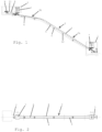
- FIG. 1 and 2 A first embodiment of a transport system according to the invention is shown, which is arranged, for example, on the slope of a mountain or hill.
- the transport system has a valley station 1 and a mountain station 2, which are connected to one another via a roadway 3.
- the roadway 3 has two parallel rails 4 which are mounted on a roadway support 5.
- the carriageway support 5 is mounted on the slope via foundations 6.
- a single vehicle 7 can be moved on the roadway 3 or its rails 4, but for representational reasons it is shown in both the valley station 1 and the mountain station 2.
- the vehicle 7 is pulled by means of a rope 8, which is driven on and unwound on a rope pulley 11 by a motor 9 arranged in the mountain station 2.
- the drive can also be located on the vehicle itself. In particular, it is also possible to use a drive system like that of a known rack railway.
- the roadway 3 has two sections 3a, 3b, with the lower section 3a having a greater gradient than the upper section 3b.
- a guideway 12 runs along the rails 4 on at least one side of the roadway 3. The distance of the guideway 12 from the rail(s) 4, more precisely from the running surface of the rails 4, is different in the two sections 3a and 3b, whereby In the illustrated embodiment, the guide track 12 is arranged essentially below one of the two rails 4. In a preferred embodiment, the lower edge or underside of the rail 4 serves as a guide track 12.
- the guide track 12 can also be a separate rail that is mounted at a suitable location.
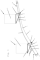
- Fig. 3 The arrangement for level control of the vehicle 7 of the embodiment of Fig. 1 and 2 is in Fig. 3 shown schematically in simplified form.
- FIG. 3 It can be seen more precisely that in the lower section 3a of the roadway 3 the distance A of the guideway or guide rail 12 from the rail 4 is larger than in section 3b.
- a guide roller 13 runs on the guide rail 12.
- the vehicle 7 has a means of transport 14, for example a cabin for transporting people and/or a container for transporting goods, and a chassis 15.
- the chassis 15 runs on the rails 4 via chassis rollers 16.
- the guide roller 13 is mounted at one end of a lever 17, which is mounted on the chassis 15 in its central region via a pivot bearing 18. With its end opposite the guide roller 13, the lever 17 is attached to the frame 19 of the transport means 14. The lever 17, and thus also the guide roller 13 mounted on it, is further connected directly to the frame 19 of the transport means 14 via a connecting element 21.
- Fig. 3 can be seen in which the vehicle 7 is shown both on the lower section 3a and on the upper section 3b.
- the means of transport 14 is always in the same horizontal orientation by being pivoted about the pivot bearing 18 relative to the chassis 15 because the distance A between the guide rail 12 and the rail 4 changes.
- the control device is arranged on both sides next to the vehicle 7.
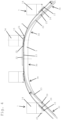
- the roadway is designed in the shape of a bridge or arch
- the roadway support 5 can be, for example, a truss, a solid reinforced concrete support, a hollow support or a combination of these or other known designs.
- the roadway 3 has three sections 3a, 3b, and 3c, which have different gradients.
- the first section 3a has, for example, a constant, positive slope with an angle of approximately +45°
- the second or middle section 3b has a slope with an angle of 0°
- the third section 3c has a negative slope with an angle of -45 ° on.
- Continuous, arcuate transitions or sections 3d, 3e are provided between these three sections 3a, 3b, 3c.
- the guide rails 4 define this course of the roadway 3.
- 4 guide tracks or guide rails 22, 23 are arranged laterally next to or outside the rails, one guide rail 22 being assigned to the first section 3a and the second guide rail 23 to the third section 3c. In the middle section 3b, the guide rails 22, 23 overlap in terms of their longitudinal extent.
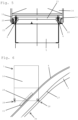
- the guide rails 22, 23 can in principle be arranged on the same side of the roadway 3, in which case they are then, as in Fig. 4 shown, lie one above the other in the middle section 3b.
- the guide rails 22, 23 can also lie on opposite sides of the roadway 3, in which case they are in the middle section 3b, as in Fig. 5 shown schematically, can also be at the same height.
- the vehicle 7 has, as in the embodiment of Fig. 1 to 3 , a chassis 15 which rolls on the rails 4 via chassis rollers 16.
- the means of transport 14 is pivotally mounted directly on the chassis 15 via a pivot bearing 24.
- the transport means 14 has two guide rollers 25, 26, one guide roller 25 being assigned to the guide rail 22 and the other guide roller 26 to the guide rail 23.
- the guide roller 25 When the vehicle 7 is in section 3a, the guide roller 25 is in engagement with the guide rail 22, where the distance A between the guide rail 22 and the rail 4 is also large due to the large gradient of the section 3a. As the vehicle 7 approaches the middle section 3b, the gradient of the roadway 3 decreases continuously, as does the distance A between the guide rail 22 and the rail 4. In the middle area 3b, the guide rail 22 finally crosses the rail 4. This allows the level or the horizontal orientation of the means of transport 14 are kept constant.
- the guide rails 22, 23 overlap at a length that is greater than the distance between the guide rollers 25, 26 measured in the direction of travel.
- the guide roller 25 is therefore still in engagement with the guide rail 22 when the guide roller 26 comes into engagement with the guide rail 23. Only then does the guide roller 25 leave the guide rail 22.
- the level control of the means of transport is subsequently taken over by the guide rail 23 and the guide roller 26, the distance A between the guide rail 23 and the rail 4 increasing to the extent that the slope of the career 3 increases negatively.
- Fig. 6 essentially corresponds to that of Fig. 4 and 5 , however instead of the U-shaped guide rails is the Fig. 4 and 5 a flat guide rail 27 is provided, which is accommodated in a pair of guide rollers 28.
Landscapes
- Engineering & Computer Science (AREA)
- Transportation (AREA)
- Mechanical Engineering (AREA)
- Platform Screen Doors And Railroad Systems (AREA)
Description
Die Erfindung betrifft ein Transportsystem mit den Merkmalen des Oberbegriffs von Anspruch 1.The invention relates to a transport system with the features of the preamble of
Derartige Transportsysteme sind beispielsweise als sogenannte Zahnradbahnen, Standseilbahnen oder Schrägaufzüge bekannt. Wenn die Fahrbahn kontinuierlich bzw. abschnittsweise unterschiedliche Steigungen aufweist, ist es unter Umständen erforderlich, das Niveau des Transportmittels, also beispielsweise einer Kabine, eines Fahrkorbs oder dergleichen, anzupassen, damit die Fahrgäste bzw. die zu transportierenden Güter auf einem horizontalen Niveau stehen können. Für diese Niveau-Anpassungen werden im Stand der Technik aufwändig geregelte Einrichtungen, beispielsweise Spindelhub- oder Hydraulik-Einheiten, eingesetzt.Such transport systems are known, for example, as so-called rack railways, funicular railways or inclined elevators. If the roadway has different gradients continuously or in sections, it may be necessary to adjust the level of the means of transport, for example a cabin, a car or the like, so that the passengers or the goods to be transported can stand on a horizontal level. In the prior art, elaborately controlled devices, such as spindle lifting or hydraulic units, are used for these level adjustments.
Aus der
Aus der
Der Erfindung liegt die Aufgabe zugrunde, ein Transportsystem der eingangs genannten Art zur Verfügung zu stellen, mit dem eine möglichst einfache und zuverlässige Anpassung des Niveaus des Fahrzeugs an unterschiedliche Steigungen durchgeführt werden kann.The invention is based on the object of providing a transport system of the type mentioned at the outset, with which the level of the vehicle can be adjusted to different gradients as simply and reliably as possible.
Gelöst wird diese Aufgabe mit einem Transportsystem mit den Merkmalen des Anspruchs 1.This task is solved with a transport system with the features of
Der Grundgedanke der Erfindung liegt darin, entlang der Fahrbahn eine Führungsbahn anzuordnen, welche auf sehr einfache und störungssichere Weise einen Niveauausgleich des Transportmittels ermöglicht.The basic idea of the invention is to arrange a guideway along the road, which is very simple and enables the level of the means of transport to be equalized in a fail-safe manner.
Beim erfindungsgemäßen Transportsystem handelt es sich um ein schienengeführtes System. D.h. dass die Fahrbahn von Schienen gebildet wird, entlang derer sich das Fahrzeug bewegt.The transport system according to the invention is a rail-guided system. This means that the roadway is formed by rails along which the vehicle moves.
Erfindungsgenmäß weist die Führungsbahn wenigstens eine Führungsschiene auf. Bevorzugt ist, dass die Führungseinrichtung wenigstens eine Führungsrolle aufweist. Anstelle einer Führungsrolle könnte bei der Erfindung aber auch eine an der Führungsschiene gleitende Einrichtung, z.B. eine Gleitkufe, verwendet werden.According to the invention, the guide track has at least one guide rail. It is preferred that the guide device has at least one guide roller. Instead of a guide roller, a device sliding on the guide rail, for example a skid, could also be used in the invention.
Die Niveauregelung kann beim erfindungsgemäßen Transportsystem damit bevorzugt auf ausschließlich mechanische Weise erfolgen, was nicht nur mit geringen Herstellungskosten, sondern auch mit geringen Wartungskosten verbunden und sehr störungssicher ist. Weitere bevorzugte Ausführungsformen der Erfindung sind Gegenstand der übrigen Unteransprüche.The level control in the transport system according to the invention can therefore preferably be carried out exclusively mechanically, which is associated not only with low manufacturing costs but also with low maintenance costs and is very reliable against faults. Further preferred embodiments of the invention are the subject of the remaining subclaims.
Weitere Merkmale und Vorteile der Erfindung ergeben sich aus der nachfolgenden Beschreibung bevorzugter Ausführungsbeispiele der Erfindung unter Bezugnahme auf die angeschlossenen Zeichnungen. Es zeigt:
- Fig. 1
- eine Seitenansicht einer ersten Ausführungsform eines erfindungsgemäßen Transportsystems,
- Fig. 2
- eine Draufsicht auf das Transportsystem von
Fig. 1 , - Fig. 3
- ein Detail des Transportsystems von
Fig. 1 und 2 in einer vergrößerten, schematischen Darstellung, - Fig. 4
- eine zweite Ausführungsform eines erfindungsgemäßen Transportsystems,
- Fig. 5
- einen Schnitt durch das Transportsystem von
Fig. 4 , und - Fig. 6
- ein Detail einer etwas geänderten Ausführungsform gemäß
Fig. 4 .
- Fig. 1
- a side view of a first embodiment of a transport system according to the invention,
- Fig. 2
- a top view of the transportation system of
Fig. 1 , - Fig. 3
- a detail of the transport system of
Fig. 1 and 2 in an enlarged, schematic representation, - Fig. 4
- a second embodiment of a transport system according to the invention,
- Fig. 5
- a section through the transport system of
Fig. 4 , and - Fig. 6
- a detail of a slightly modified embodiment according to
Fig. 4 .
In den
Auf der Fahrbahn 3 bzw. deren Schienen 4 ist in der dargestellten Ausführungsform ein einziges Fahrzeug 7 verfahrbar, das aus darstellerischen Gründen allerdings sowohl in der Talstation 1 als auch in der Bergstation 2 eingezeichnet ist. Das Fahrzeug 7 wird in der dargestellten Ausführungsform mittels eines Seiles 8 gezogen, das von einem in der Bergstation 2 angeordneten Motor 9 angetrieben auf einer Seilrolle 11 aufund abgewickelt wird. Der Antrieb kann sich aber auch am Fahrzeug selbst befinden. Insbesondere ist es auch möglich, ein Antriebssystem wie bei einer an sich bekannten Zahnradbahn zu verwenden.In the embodiment shown, a
Die Fahrbahn 3 weist in der dargestellten Ausführungsform zwei Abschnitte 3a, 3b auf, wobei der untere Abschnitt 3a eine größere Steigung aufweist, als der obere Abschnitt 3b. Entlang der Schienen 4 verläuft auf wenigstens einer Seite der Fahrbahn 3 eine Führungsbahn 12. Der Abstand der Führungsbahn 12 von der bzw. den Schienen 4, genauer gesagt von der Lauffläche der Schienen 4, ist in den beiden Abschnitten 3a und 3b unterschiedlich groß, wobei in der dargestellten Ausführungsform die Führungsbahn 12 im Wesentlichen unterhalb einer der beiden Schienen 4 angeordnet ist. In einer bevorzugten Ausführungsform dient die Unterkante oder Unterseite der Schiene 4 als Führungsbahn 12. Die Führungsbahn 12 kann aber auch eine separate Schiene sein, die an geeigneter Stelle montiert ist.In the embodiment shown, the
Die Anordnung zur Niveauregelung des Fahrzeugs 7 der Ausführungsform von
In
Die Führungsrolle 13 ist an einem Ende eines Hebels 17 gelagert, der in seinem Mittelbereich über ein Schwenklager 18 am Fahrwerk 15 gelagert ist. Mit seinem der Führungsrolle 13 gegenüberliegenden Ende ist der Hebel 17 am Rahmen 19 des Transportmittels 14 befestigt. Der Hebel 17, und somit auch die an diesem gelagerte Führungsrolle 13, ist des Weiteren über ein Verbindungselement 21 direkt mit dem Rahmen 19 des Transportmittels 14 verbunden.The
Der Hebel 17 bildet in Verbindung mit dem Verbindungselement 21 und der Führungsrolle 13 eine Steuereinrichtung, mit welcher das Niveau, genauer gesagt die horizontale Ausrichtung, des Transportmittels 14 sichergestellt wird, während sich das Fahrzeug 7 entlang der Abschnitte 3a und 3b, welche unterschiedliche Steigungen aufweisen, bewegt. Dies ist in
In den
Die Fahrbahn 3 weist in diesem Fall drei Abschnitte 3a, 3b, und 3c auf, welche unterschiedliche Steigungen haben. Insbesondere weist der erste Abschnitt 3a eine beispielsweise konstante, positive Steigung mit einem Winkel von etwa +45°, der zweite bzw. mittlere Abschnitt 3b eine Steigung mit einem Winkel von 0° und der dritte Abschnitt 3c eine negative Steigung mit einem Winkel von -45° auf. Zwischen diesen drei Abschnitten 3a, 3b, 3c sind kontinuierliche, bogenförmige Übergänge bzw. Abschnitte 3d, 3e vorgesehen. Die Führungsschienen 4 definieren diesen Verlauf der Fahrbahn 3.In this case, the
In der dargestellten Ausführungsform sind seitlich neben bzw. außerhalb der Schienen 4 Führungsbahnen bzw. Führungsschienen 22, 23 angeordnet, wobei die eine Führungsschiene 22 dem ersten Abschnitt 3a und die zweite Führungsschiene 23 dem dritten Abschnitt 3c zugeordnet ist. Im mittleren Abschnitt 3b überlappen sich die Führungsschienen 22, 23 hinsichtlich ihrer Längserstreckung.In the embodiment shown, 4 guide tracks or
Die Führungsschienen 22, 23 können grundsätzlich auf derselben Seite der Fahrbahn 3 angeordnet sein, wobei sie dann, wie in
Das Fahrzeug 7 weist, wie bereits in der Ausführungsform der
Wenn sich das Fahrzeug 7 im Abschnitt 3a befindet, ist die Führungsrolle 25 in Eingriff mit der Führungsschiene 22, wobei der Abstand A zwischen der Führungsschiene 22 und der Schiene 4 aufgrund der großen Steigung des Abschnitts 3a ebenfalls groß ist. Wenn sich das Fahrzeug 7 dem mittleren Abschnitt 3b nähert, nimmt die Steigung der Fahrbahn 3 kontinuierlich ab, ebenso wie der Abstand A zwischen der Führungsschiene 22 und der Schiene 4. Im Mittelbereich 3b kreuzt die Führungsschiene 22 schließlich die Schiene 4. Damit kann das Niveau bzw. die horizontale Ausrichtung des Transportmittels 14 konstant gehalten werden.When the
Im mittleren Abschnitt 3b überlappen sich die Führungsschienen 22, 23 in einer Länge, die größer als der in Fahrtrichtung gemessene Abstand der Führungsrollen 25, 26 ist. Damit befindet sich die Führungsrolle 25 noch in Eingriff mit der Führungsschiene 22, wenn die Führungsrolle 26 in Eingriff mit der Führungsschiene 23 kommt. Erst danach verlässt die Führungsrolle 25 die Führungsschiene 22. Die Niveauregelung des Transportmittels wird in weiterer Folge von der Führungsschiene 23 und der Führungsrolle 26 übernommen, wobei der Abstand A zwischen der Führungsschiene 23 und der Schiene 4 in dem Ausmaß zunimmt, in dem die Steigung der Laufbahn 3 ins Negative zunimmt.In the
Die Ausführungsform von
Anstelle von zwei getrennten Führungsschienen 22, 23 könnte auch nur eine einzige, durchgehende Führungsschiene verwendet werden, wobei dann im mittleren Bereich 3b abwechselnd eine der beiden Führungsrollen 25, 26 in Eingriff bzw. außer Eingriff mit der Führungsschiene gebracht werden müsste.Instead of two
Es versteht sich, dass die Niveauregelung der Ausführungsform gemäß
- AA
- AbstandDistance
- 11
- TalstationValley station
- 22
- BergstationHill station
- 33
- Fahrbahnroadway
- 44
- Schienenrails
- 55
- Fahrbahnträgerroadway support
- 66
- FundamenteFoundations
- 77
- Fahrzeugvehicle
- 88th
- SeilRope
- 99
- Motorengine
- 1010
- --
- 1111
- Seilrollepulley
- 1212
- Führungsbahn, FührungsschieneGuideway, guide rail
- 1313
- Führungsrolleleadership role
- 1414
- TransportmittelMode of Transport
- 1515
- Fahrwerklanding gear
- 1616
- FahrwerksrollenUndercarriage rollers
- 1717
- Hebellever
- 1818
- SchwenklagerPivot bearing
- 1919
- RahmenFrame
- 2020
- --
- 2121
- Verbindungselementconnecting element
- 2222
- FührungsschieneGuide rail
- 2323
- FührungsschieneGuide rail
- 2424
- SchwenklagerPivot bearing
- 2525
- Führungsrolleleadership role
- 2626
- Führungsrolleleadership role
- 2727
- FührungsschieneGuide rail
- 2828
- FührungsrollenpaarPair of guide rollers
- 2929
- FührungsrollenpaarPair of guide rollers
Claims (15)
- Transport system having at least one vehicle (7) which comprises a transport means (14), in particular a cab, a bogie (15) and rails (4), wherein the bogie (15) rolls via bogie rollers (16) on a track (3) formed by the rails (4) and with which the vehicle (7) can be moved along the track (3), wherein the track (3) has at least two sections (3a to 3d) with different gradients, wherein the transport means (14) is mounted on the bogie (15) so as to be movable in the vertical direction and pivotable (24), wherein a guide track extends along the track (3) which is at a different distance from the track (3) in sections (3a to 3e), wherein a guide device is guided along the guide track, and wherein the transport means (14) is connected to the guide device for level control, so that the level respectively the horizontal alignment of the transport means (14) is kept constant, characterized in that the guide track has at least one guide rail (12, 22, 23, 27) arranged essentially underneath one of the rails (4) or extends on the lower edge respectively the underside of one of the rails (4).
- Transport system according to claim 1, characterized in that the guide device is arranged on the transport means (14) and preferably has at least one guide roller (13, 25, 26, 28) or a skid.
- Transport system according to claim 1 or 2, characterized in that the transport means (14) is connected to the guide device via a preferably mechanical control device.
- Transport system according to claim 3, characterized in that the control device comprises a lever system.
- Transport system according to claim 4, characterized in that the transport means (14) is mounted on the bogie (15) via a lever (17), and in that the guide device is arranged on the lever (17).
- Transport system according to claim 5, characterized in that the transport means (14) is connected to the guide device by means of a connecting element.
- Transport system according to one of claims 1 to 6, characterized in that the track (3) has both a positive and a negative gradient.
- Transport system according to claim 7, characterized in that two guide devices are provided, which are alternately guided along the guide track.
- Transport system according to claim 8, characterized in that the guide devices can be brought into and out of engagement with the guide track.
- Transport system according to claim 8, characterized in that two guide tracks are provided, along each of which a guide device is guided.
- Transport system according to claim 10, characterized in that the guide tracks overlap in a transition region.
- Transport system according to one of claims 1 to 11, characterized in that the track (3) is curved at least in sections (3d, 3e) in the shape of an arc.
- Transport system according to one of claims 1 to 12, characterized in that it has a track support (5) with two sections (3a, 3c, 3d, 3e) which are inclined substantially in an A-shape with respect to one another.
- Transport system according to claim 13, characterized in that at least one of the inclined sections (3d, 3e) is of arcshaped design.
- Transport system according to one of claims 1 to 14, characterized in that the vehicle (7) is cable-drawn or a rack railroad.
Applications Claiming Priority (2)
| Application Number | Priority Date | Filing Date | Title |
|---|---|---|---|
| ATA568/2016A AT519537A1 (en) | 2016-12-15 | 2016-12-15 | Transport system with a cable-drawn vehicle |
| PCT/EP2017/081545 WO2018108634A1 (en) | 2016-12-15 | 2017-12-05 | Transport system comprising a cable-drawn vehicle |
Publications (4)
| Publication Number | Publication Date |
|---|---|
| EP3554912A1 EP3554912A1 (en) | 2019-10-23 |
| EP3554912C0 EP3554912C0 (en) | 2023-07-12 |
| EP3554912B1 EP3554912B1 (en) | 2023-07-12 |
| EP3554912B9 true EP3554912B9 (en) | 2023-10-04 |
Family
ID=60574617
Family Applications (1)
| Application Number | Title | Priority Date | Filing Date |
|---|---|---|---|
| EP17808932.2A Active EP3554912B9 (en) | 2016-12-15 | 2017-12-05 | Transport system comprising a cable-drawn vehicle |
Country Status (3)
| Country | Link |
|---|---|
| EP (1) | EP3554912B9 (en) |
| AT (1) | AT519537A1 (en) |
| WO (1) | WO2018108634A1 (en) |
Families Citing this family (1)
| Publication number | Priority date | Publication date | Assignee | Title |
|---|---|---|---|---|
| CN109279291B (en) * | 2018-12-05 | 2020-10-27 | 龙南格林园艺制品有限公司 | Mountain land rail transport system |
Family Cites Families (8)
| Publication number | Priority date | Publication date | Assignee | Title |
|---|---|---|---|---|
| FR1405060A (en) * | 1964-08-25 | 1965-07-02 | Inventio Ag | Safety device for wheeled basket carriers |
| SU1096145A1 (en) * | 1981-12-21 | 1984-06-07 | Специализированное Конструкторское Бюро Эскалаторостроения | Inclined lift |
| FR2603852B3 (en) * | 1986-09-11 | 1989-08-18 | Giauffret Georges | FUNCULAR FOR VARIABLE SLOPE WITH DOWNSTREAM AND UPSTREAM WHEELS ROLLING ON INDEPENDENT TRACKS ON THEIR SLOPE AND SPREAD AND ITS CENTRIFUGAL BRAKING DEVICE |
| CH681613A5 (en) * | 1990-03-02 | 1993-04-30 | Von Roll Transportsysteme | Railway for track of varying inclination - has regulating body with drive between vehicle body and chassis, and roller, moving on track |
| CH683167A5 (en) * | 1990-05-18 | 1994-01-31 | Rodolphe Nieth | Transport installation - includes tracked vehicle having cabin mounted on wheels with rails serving as guides and width of cabin slightly less than spacing of wheels |
| FI961810A0 (en) * | 1996-01-03 | 1996-04-26 | Valmet Corp | Anordning Foer transport av pappersrullar |
| JP6124525B2 (en) * | 2012-07-18 | 2017-05-10 | 日本ケーブル株式会社 | Rescue operation device for rope-drawing transportation equipment |
| US10308482B2 (en) * | 2015-05-06 | 2019-06-04 | Otis Elevator Company | Tread element for people conveyor comprising a cantilever arm |
-
2016
- 2016-12-15 AT ATA568/2016A patent/AT519537A1/en not_active Application Discontinuation
-
2017
- 2017-12-05 WO PCT/EP2017/081545 patent/WO2018108634A1/en unknown
- 2017-12-05 EP EP17808932.2A patent/EP3554912B9/en active Active
Also Published As
| Publication number | Publication date |
|---|---|
| AT519537A1 (en) | 2018-07-15 |
| EP3554912A1 (en) | 2019-10-23 |
| EP3554912C0 (en) | 2023-07-12 |
| EP3554912B1 (en) | 2023-07-12 |
| WO2018108634A1 (en) | 2018-06-21 |
Similar Documents
| Publication | Publication Date | Title |
|---|---|---|
| DE3206630C2 (en) | ||
| DE60201341T2 (en) | HOCHBAHN | |
| EP1840072B1 (en) | Crane with boom and raceway for cable roller assemblies | |
| DE1104985B (en) | Roller plate device for closing openings in open-topped rooms in fixed or mobile systems in vehicles | |
| DE19816768C2 (en) | Device for transporting roller coaster carriages | |
| DE102011002334A1 (en) | Current collector system for vehicle, has current collector carriage that is arranged on outer arm, which is displaced by pivoting arms transversely to direction of travel of vehicle from standby position to engaged position | |
| EP3554912B9 (en) | Transport system comprising a cable-drawn vehicle | |
| EP1834042B1 (en) | Machine for renovation of a track | |
| DE102008059711A1 (en) | Device for transferring objects and conveyor systems with such a device | |
| DE202010008641U1 (en) | Device for transporting vehicles of a track-guided amusement ride | |
| DE3522918A1 (en) | Device for the transport of a track section or of a mounted track connection on the railway line | |
| DE2228196C3 (en) | Device for changing track yokes | |
| DE2910867A1 (en) | TRANSPORT SYSTEM | |
| DE1405561A1 (en) | Inclined elevator | |
| DE10132351A1 (en) | conveyor system | |
| DE655748C (en) | Movable sliding platform for conveyor wagons in the mine | |
| EP3699121B1 (en) | Access system for rtc, shifting vehicle and method for providing access | |
| DE3340739A1 (en) | Track construction machine for exchanging a mounted track section or a mounted track connection | |
| DE4237802C1 (en) | Self chain driven transport system - comprises vehicle units set at intervals on supports with locators for rollers over which runs motor driven chain drive to pull vehicle | |
| DE3719778C1 (en) | Apparatus for transporting and laying beam-like supports made of steel, reinforced or prestressed concrete | |
| DE850795C (en) | Portal-like device for lifting, moving and depositing loads | |
| EP1467024B1 (en) | Device for placing rails in a railway track | |
| EP3221518B1 (en) | Sectional lane-supporting bridge, and method for laying a sectional lane-supporting bridge | |
| DE217727C (en) | ||
| WO2024052523A1 (en) | Passive points for a rail-based transport system, bogie for a rail-based transport system and rail-based transport system |
Legal Events
| Date | Code | Title | Description |
|---|---|---|---|
| STAA | Information on the status of an ep patent application or granted ep patent |
Free format text: STATUS: UNKNOWN |
|
| STAA | Information on the status of an ep patent application or granted ep patent |
Free format text: STATUS: THE INTERNATIONAL PUBLICATION HAS BEEN MADE |
|
| PUAI | Public reference made under article 153(3) epc to a published international application that has entered the european phase |
Free format text: ORIGINAL CODE: 0009012 |
|
| STAA | Information on the status of an ep patent application or granted ep patent |
Free format text: STATUS: REQUEST FOR EXAMINATION WAS MADE |
|
| 17P | Request for examination filed |
Effective date: 20190712 |
|
| AK | Designated contracting states |
Kind code of ref document: A1 Designated state(s): AL AT BE BG CH CY CZ DE DK EE ES FI FR GB GR HR HU IE IS IT LI LT LU LV MC MK MT NL NO PL PT RO RS SE SI SK SM TR |
|
| AX | Request for extension of the european patent |
Extension state: BA ME |
|
| DAV | Request for validation of the european patent (deleted) | ||
| DAX | Request for extension of the european patent (deleted) | ||
| STAA | Information on the status of an ep patent application or granted ep patent |
Free format text: STATUS: EXAMINATION IS IN PROGRESS |
|
| 17Q | First examination report despatched |
Effective date: 20211223 |
|
| GRAP | Despatch of communication of intention to grant a patent |
Free format text: ORIGINAL CODE: EPIDOSNIGR1 |
|
| STAA | Information on the status of an ep patent application or granted ep patent |
Free format text: STATUS: GRANT OF PATENT IS INTENDED |
|
| INTG | Intention to grant announced |
Effective date: 20230203 |
|
| GRAS | Grant fee paid |
Free format text: ORIGINAL CODE: EPIDOSNIGR3 |
|
| GRAA | (expected) grant |
Free format text: ORIGINAL CODE: 0009210 |
|
| STAA | Information on the status of an ep patent application or granted ep patent |
Free format text: STATUS: THE PATENT HAS BEEN GRANTED |
|
| AK | Designated contracting states |
Kind code of ref document: B1 Designated state(s): AL AT BE BG CH CY CZ DE DK EE ES FI FR GB GR HR HU IE IS IT LI LT LU LV MC MK MT NL NO PL PT RO RS SE SI SK SM TR |
|
| REG | Reference to a national code |
Ref country code: CH Ref legal event code: EP |
|
| REG | Reference to a national code |
Ref country code: DE Ref legal event code: R096 Ref document number: 502017015057 Country of ref document: DE |
|
| REG | Reference to a national code |
Ref country code: IE Ref legal event code: FG4D Free format text: LANGUAGE OF EP DOCUMENT: GERMAN |
|
| U01 | Request for unitary effect filed |
Effective date: 20230726 |
|
| U07 | Unitary effect registered |
Designated state(s): AT BE BG DE DK EE FI FR IT LT LU LV MT NL PT SE SI Effective date: 20230801 |
|
| REG | Reference to a national code |
Ref country code: CH Ref legal event code: PK Free format text: BERICHTIGUNG B9 |
|
| REG | Reference to a national code |
Ref country code: LT Ref legal event code: MG9D |
|
| U20 | Renewal fee paid [unitary effect] |
Year of fee payment: 7 Effective date: 20231214 |
|
| PG25 | Lapsed in a contracting state [announced via postgrant information from national office to epo] |
Ref country code: GR Free format text: LAPSE BECAUSE OF FAILURE TO SUBMIT A TRANSLATION OF THE DESCRIPTION OR TO PAY THE FEE WITHIN THE PRESCRIBED TIME-LIMIT Effective date: 20231013 |
|
| PG25 | Lapsed in a contracting state [announced via postgrant information from national office to epo] |
Ref country code: ES Free format text: LAPSE BECAUSE OF FAILURE TO SUBMIT A TRANSLATION OF THE DESCRIPTION OR TO PAY THE FEE WITHIN THE PRESCRIBED TIME-LIMIT Effective date: 20230712 |
|
| PG25 | Lapsed in a contracting state [announced via postgrant information from national office to epo] |
Ref country code: IS Free format text: LAPSE BECAUSE OF FAILURE TO SUBMIT A TRANSLATION OF THE DESCRIPTION OR TO PAY THE FEE WITHIN THE PRESCRIBED TIME-LIMIT Effective date: 20231112 |
|
| PG25 | Lapsed in a contracting state [announced via postgrant information from national office to epo] |
Ref country code: RS Free format text: LAPSE BECAUSE OF FAILURE TO SUBMIT A TRANSLATION OF THE DESCRIPTION OR TO PAY THE FEE WITHIN THE PRESCRIBED TIME-LIMIT Effective date: 20230712 Ref country code: NO Free format text: LAPSE BECAUSE OF FAILURE TO SUBMIT A TRANSLATION OF THE DESCRIPTION OR TO PAY THE FEE WITHIN THE PRESCRIBED TIME-LIMIT Effective date: 20231012 Ref country code: IS Free format text: LAPSE BECAUSE OF FAILURE TO SUBMIT A TRANSLATION OF THE DESCRIPTION OR TO PAY THE FEE WITHIN THE PRESCRIBED TIME-LIMIT Effective date: 20231112 Ref country code: HR Free format text: LAPSE BECAUSE OF FAILURE TO SUBMIT A TRANSLATION OF THE DESCRIPTION OR TO PAY THE FEE WITHIN THE PRESCRIBED TIME-LIMIT Effective date: 20230712 Ref country code: GR Free format text: LAPSE BECAUSE OF FAILURE TO SUBMIT A TRANSLATION OF THE DESCRIPTION OR TO PAY THE FEE WITHIN THE PRESCRIBED TIME-LIMIT Effective date: 20231013 Ref country code: ES Free format text: LAPSE BECAUSE OF FAILURE TO SUBMIT A TRANSLATION OF THE DESCRIPTION OR TO PAY THE FEE WITHIN THE PRESCRIBED TIME-LIMIT Effective date: 20230712 |
|
| PG25 | Lapsed in a contracting state [announced via postgrant information from national office to epo] |
Ref country code: PL Free format text: LAPSE BECAUSE OF FAILURE TO SUBMIT A TRANSLATION OF THE DESCRIPTION OR TO PAY THE FEE WITHIN THE PRESCRIBED TIME-LIMIT Effective date: 20230712 |
|
| REG | Reference to a national code |
Ref country code: DE Ref legal event code: R097 Ref document number: 502017015057 Country of ref document: DE |
|
| PG25 | Lapsed in a contracting state [announced via postgrant information from national office to epo] |
Ref country code: SM Free format text: LAPSE BECAUSE OF FAILURE TO SUBMIT A TRANSLATION OF THE DESCRIPTION OR TO PAY THE FEE WITHIN THE PRESCRIBED TIME-LIMIT Effective date: 20230712 Ref country code: RO Free format text: LAPSE BECAUSE OF FAILURE TO SUBMIT A TRANSLATION OF THE DESCRIPTION OR TO PAY THE FEE WITHIN THE PRESCRIBED TIME-LIMIT Effective date: 20230712 Ref country code: CZ Free format text: LAPSE BECAUSE OF FAILURE TO SUBMIT A TRANSLATION OF THE DESCRIPTION OR TO PAY THE FEE WITHIN THE PRESCRIBED TIME-LIMIT Effective date: 20230712 Ref country code: SK Free format text: LAPSE BECAUSE OF FAILURE TO SUBMIT A TRANSLATION OF THE DESCRIPTION OR TO PAY THE FEE WITHIN THE PRESCRIBED TIME-LIMIT Effective date: 20230712 |
|
| PLBE | No opposition filed within time limit |
Free format text: ORIGINAL CODE: 0009261 |
|
| STAA | Information on the status of an ep patent application or granted ep patent |
Free format text: STATUS: NO OPPOSITION FILED WITHIN TIME LIMIT |
|
| 26N | No opposition filed |
Effective date: 20240415 |
|
| REG | Reference to a national code |
Ref country code: CH Ref legal event code: PL |
|
| PG25 | Lapsed in a contracting state [announced via postgrant information from national office to epo] |
Ref country code: MC Free format text: LAPSE BECAUSE OF FAILURE TO SUBMIT A TRANSLATION OF THE DESCRIPTION OR TO PAY THE FEE WITHIN THE PRESCRIBED TIME-LIMIT Effective date: 20230712 |
|
| GBPC | Gb: european patent ceased through non-payment of renewal fee |
Effective date: 20231205 |
|
| PG25 | Lapsed in a contracting state [announced via postgrant information from national office to epo] |
Ref country code: MC Free format text: LAPSE BECAUSE OF FAILURE TO SUBMIT A TRANSLATION OF THE DESCRIPTION OR TO PAY THE FEE WITHIN THE PRESCRIBED TIME-LIMIT Effective date: 20230712 |