EP3554768B1 - Poste de sécurité, laboratoire mobile et procédure - Google Patents
Poste de sécurité, laboratoire mobile et procédure Download PDFInfo
- Publication number
- EP3554768B1 EP3554768B1 EP17823061.1A EP17823061A EP3554768B1 EP 3554768 B1 EP3554768 B1 EP 3554768B1 EP 17823061 A EP17823061 A EP 17823061A EP 3554768 B1 EP3554768 B1 EP 3554768B1
- Authority
- EP
- European Patent Office
- Prior art keywords
- impact load
- safety workbench
- maximum permissible
- working space
- detected
- Prior art date
- Legal status (The legal status is an assumption and is not a legal conclusion. Google has not performed a legal analysis and makes no representation as to the accuracy of the status listed.)
- Active
Links
Images


Classifications
-
- B—PERFORMING OPERATIONS; TRANSPORTING
- B08—CLEANING
- B08B—CLEANING IN GENERAL; PREVENTION OF FOULING IN GENERAL
- B08B15/00—Preventing escape of dirt or fumes from the area where they are produced; Collecting or removing dirt or fumes from that area
- B08B15/02—Preventing escape of dirt or fumes from the area where they are produced; Collecting or removing dirt or fumes from that area using chambers or hoods covering the area
- B08B15/026—Boxes for removal of dirt, e.g. for cleaning brakes, glove- boxes
-
- B—PERFORMING OPERATIONS; TRANSPORTING
- B08—CLEANING
- B08B—CLEANING IN GENERAL; PREVENTION OF FOULING IN GENERAL
- B08B15/00—Preventing escape of dirt or fumes from the area where they are produced; Collecting or removing dirt or fumes from that area
-
- B—PERFORMING OPERATIONS; TRANSPORTING
- B25—HAND TOOLS; PORTABLE POWER-DRIVEN TOOLS; MANIPULATORS
- B25H—WORKSHOP EQUIPMENT, e.g. FOR MARKING-OUT WORK; STORAGE MEANS FOR WORKSHOPS
- B25H1/00—Work benches; Portable stands or supports for positioning portable tools or work to be operated on thereby
- B25H1/20—Work benches; Portable stands or supports for positioning portable tools or work to be operated on thereby with provision for shielding the work area
-
- B—PERFORMING OPERATIONS; TRANSPORTING
- B08—CLEANING
- B08B—CLEANING IN GENERAL; PREVENTION OF FOULING IN GENERAL
- B08B15/00—Preventing escape of dirt or fumes from the area where they are produced; Collecting or removing dirt or fumes from that area
- B08B15/02—Preventing escape of dirt or fumes from the area where they are produced; Collecting or removing dirt or fumes from that area using chambers or hoods covering the area
-
- F—MECHANICAL ENGINEERING; LIGHTING; HEATING; WEAPONS; BLASTING
- F24—HEATING; RANGES; VENTILATING
- F24F—AIR-CONDITIONING; AIR-HUMIDIFICATION; VENTILATION; USE OF AIR CURRENTS FOR SCREENING
- F24F8/00—Treatment, e.g. purification, of air supplied to human living or working spaces otherwise than by heating, cooling, humidifying or drying
- F24F8/10—Treatment, e.g. purification, of air supplied to human living or working spaces otherwise than by heating, cooling, humidifying or drying by separation, e.g. by filtering
Definitions
- the present invention relates to a safety workbench for a mobile laboratory, a mobile laboratory with such a safety workbench and a method for determining an impact load on such a safety workbench.
- microbiological safety workbenches must be subjected to an installation test after each change of location. In such an installation test, it is checked whether leaks occur in the safety workbench that were caused by the change in location of the safety workbench. In mobile laboratories, such as vehicles, this means that such an installation test is required when or after each change of location of the mobile laboratory. A frequent change of location of such a mobile laboratory can therefore be associated with a considerable financial and time effort.
- the DE 10 2009 052 013 A1 describes a safety cabinet for examining nuclear, biological and/or chemical warfare agents that can be used in vehicles.
- the DE 102 17 904 C1 shows a safety workbench with a work space that is surrounded by a housing and is accessible on the front side of the housing via a work opening that can be closed with an adjustable front pane.
- the safety workbench has a safety monitoring system for monitoring various device functions. Also part of the safety monitoring system is a processor which arithmetically links measured data determined during the monitoring of specified device functions and/or device parameters stored in the safety monitoring system in such a way that the result is a code number that allows conclusions to be drawn about the overall state of the safety workbench.
- the DE 41 39 728 C1 describes an electronic transport monitoring device for registering shock and impact loads in moving goods, which works independently of the mains and automatically over a longer period of time, as well as precisely determining, evaluating and storing measured values in a loss-proof manner.
- an object of the present invention is to provide an improved safety workbench for a mobile laboratory.
- the safety workbench includes a work space for examining a sample, and a measuring arrangement that is set up to detect an impact load acting on the work space and to compare it with a maximum permissible impact load.
- the installation check of the safety workbench can be restricted to being carried out only when the maximum permissible impact load is exceeded.
- installation tests that are not absolutely necessary can be dispensed with, since as long as the maximum permissible impact load is not exceeded, it can be assumed that the safety workbench does not have any leaks and therefore no installation test is required. This results in significant time and cost savings when operating a mobile laboratory with such a safety workbench.
- the measuring arrangement is set up to detect the impact load acting on the working space in at least one spatial direction and to compare it with a maximum permissible impact load acting in the at least one spatial direction.
- Three spatial directions are preferably provided, which are in particular positioned perpendicular to one another.
- the measuring arrangement is preferably set up to detect the impact load as individual force vectors acting in the respective spatial directions and/or as a resultant total force vector oriented in any way with respect to the spatial directions.
- the installation test is required when the impact load acting as individual force vectors exceeds the maximum permissible impact load in the corresponding spatial direction. However, the installation test may also be necessary if the individual force vectors do not yet exceed the maximum permissible impact load, but the total force vector resulting from the impact load is greater than the maximum permissible maximum impact load in at least one of the spatial directions. If the maximum allowable shock load is exceeded, a signal can be issued indicating the need for a new installation check.
- the installation test is preferably a tightness test or a test for leaks.
- Impact loading can also be referred to as shock loading.
- the mobile laboratory can be a vehicle, such as a land vehicle, a rail vehicle, a water vehicle, or an aircraft.
- the safety workbench is preferably a microbiological safety workbench. However, the safety workbench can also be suitable for examining chemical samples and/or samples contaminated with atoms.
- the safety workbench can also be referred to as a mobile safety workbench, in particular as a mobile microbiological safety workbench.
- the fact that the safety workbench is “mobile” means in particular that the safety workbench is sufficiently small, stable and/or light to be installed in a vehicle.
- the sample is preferably a microbiological sample.
- the impact load can be positive or negative. That is, the shock load can be positive acceleration or negative acceleration or deceleration.
- the maximum permissible impact load on the safety workbench is recorded with the aid of the measuring arrangement.
- a negative pressure is preferably generated in the working space, and the pressure in the working space is recorded and logged during and after the test movement.
- no significant change in pressure can be measured during the test movement. This ensures that the mechanical stress on the safety workbench during the test movement does not result in a change in pressure due to a leak.
- the maximum shock load that occurs ie the maximum acceleration and deceleration values, is determined, programmed as limit values and stored for an optional alarm triggering with the help of a signaling device.
- the recorded maximum shock loads are preferably programmed as limit values. They are used in particular to trigger an alarm, i.e. as a means of providing information as to whether an installation check must be carried out after a change of location or whether this can be omitted.
- the measuring arrangement is preferably set up to record the shock load in three axes or in three spatial directions, to store it and to compare it with the maximum permissible shock load.
- the measuring arrangement for measuring the impact load that is to say for measuring the maximum acceleration or for measuring the maximum deceleration, preferably comprises at least one measuring device which can record the impact load, preferably in three spatial directions.
- the measuring device is preferably assigned to the measuring arrangement.
- the measuring device can also be referred to as an impact sensor or shock sensor.
- Measurement data from the measuring device are then preferably transmitted via an interface to a computing device with a storage medium.
- a computing device For example, a so-called data logger can function, that is, a process-controlled storage unit that is electrically connected to the measuring arrangement or is assigned to it. This computing device preferably records measurement data from a measurement at a specific, definable rhythm and stores them on the storage medium.
- the measured values determined and measured are stored in the storage medium of the computing device and then compared with the stored limit values in the computing device.
- the computing device can comprise an evaluation unit, for example an integrated circuit, in particular a microchip.
- the signaling device is preferably connected downstream of the computing device. During or after a change of location of the mobile laboratory, the signaling device preferably only generates a signal, in particular an alarm signal, if the impact load on the safety cabinet during the change of location has exceeded at least one of the specified limit values with regard to the maximum permissible impact load. However, there is no corresponding information if the shock load remains within the preset limit values.
- the measurement data and the limit values can also be displayed on a display device, for example a monitor, in order to enable an alternative, in particular manual, or additional check.
- the measurement arrangement can also include a position and time determination system, such as GPS, GLONASS, BeiDou, Galileo/GNSS or the like, or work with the aid of such a system.
- a data profile of the position and time determination system can contain various vehicle data, such as spring deflection of a wheel suspension over time, but also data of an existing terrain profile, which can be used to assess the shock load occurring when the location changes. These should preferably be transferred to a Cartesian coordinate system so that they can then be compared with the limit values for the maximum impact load.
- the safety workbench includes a signaling device that is set up to emit a signal as soon as the detected impact load exceeds the maximum permissible impact load.
- the signaling device can also be in the form of a display device, for example a monitor, or can include a display device.
- the signaling device is set up to emit an optical and/or acoustic signal.
- the signaling device can comprise an optical signal transmitter, such as a light-emitting diode or the like.
- the signaling device can also have an acoustic signal transmitter.
- the signaling device can also be a screen or monitor on which the recorded impact load is displayed.
- a display device, in particular a monitor can be provided in addition to the signaling device.
- the maximum permissible shock load, particularly in each spatial direction is programmed as a limit value for triggering an alarm. As long as this limit value is not exceeded, it can be assumed that the change of location has not led to leaks in the work area, which means that an installation test can be omitted.
- the measuring arrangement comprises a measuring device which is set up to detect the impact load acting on the working space, and a computing device in which the maximum permissible impact load is stored and which is set up to calculate the impact load detected using the measuring device compared with the maximum allowable shock load.
- the measuring device is set up to detect the impact load acting on the working space in the at least one spatial direction.
- the maximum permissible impact load acting in the at least one spatial direction is preferably stored in the computing device.
- the computing device preferably includes a storage medium on which the maximum permissible impact load acting in the at least one spatial direction is stored.
- the computing device can be what is known as a data logger.
- the computing device can include the measuring device and/or the signaling device.
- the computing device is preferably coupled to the measuring device with the aid of an interface.
- the measuring device can include one or more sensors, in particular acceleration sensors.
- the computing device can include an evaluation unit, for example an integrated circuit.
- the measuring device is set up to detect the impact load acting on the working area in three different spatial directions, with a maximum permissible impact load being stored in the computing device for each spatial direction, and with the computing device controlling a signaling device in such a way that it generates a signal outputs as soon as the detected shock load exceeds the maximum permissible shock load in at least one of the spatial directions.
- a first spatial direction or x-direction, a second spatial direction or y-direction and a third spatial direction or z-direction are preferably provided.
- the three spatial directions preferably form a coordinate system.
- the measuring device can also be set up to detect a respective rotational movement about the spatial directions.
- the measuring device can include torque or yaw sensors.
- the computing device also controls the signaling device when the impact load recorded exceeds the maximum permissible impact load in two of the three spatial directions or in all three spatial directions. However, the signaling device is always activated when the maximum permissible impact load is already in just one of the spatial directions is exceeded.
- the signaling device can also be activated when the individual force vectors do not yet exceed the maximum permissible impact load, but the total force vector resulting from the impact load is greater than the maximum permissible maximum impact load, in particular in at least one of the spatial directions.
- the measuring device comprises at least one acceleration sensor.
- the acceleration sensor can be set up to detect the acceleration of the safety workbench in the first spatial direction, in the second spatial direction and in the third spatial direction.
- the measuring device can also have its own acceleration sensor for each spatial direction.
- the measuring device can also include or use a position and time determination system.
- the measuring device is set up to detect the impact load acting on the work area in at least one spatial direction during a change of location of the safety workbench.
- a change of location also includes a transport or a shock to the safety workbench, for example when it is loaded or when it is hit by a mine.
- a mobile laboratory, in particular a vehicle, with such a safety workbench is also proposed.
- the vehicle can be, for example, a rail vehicle, a land vehicle, a watercraft or an aircraft.
- the mobile laboratory can include several such safety cabinets.
- a method for determining an impact load on a safety workbench for a mobile laboratory comprises the following steps: detecting an impact load acting on a working area of the safety workbench, and comparing the detected impact load with a maximum permissible impact load.
- the impact load acting on the working space is detected in at least one spatial direction and compared with a maximum permissible impact load acting in the at least one spatial direction.
- the shock load is preferably recorded as individual force vectors acting in the respective spatial directions and/or as a resultant total force vector oriented in any way with respect to the spatial directions.
- the steps of detecting and comparing can be performed sequentially or simultaneously.
- the measuring arrangement described above is used for this purpose.
- the comparison can also be carried out visually, for example on a screen. With the help of the method it can thus be determined whether a renewed installation check of the safety workbench is required or whether this can be dispensed with. This enables cost and time savings.
- a signal is issued as soon as the detected shock load exceeds the maximum permissible shock load.
- the signal can be optical and/or acoustic.
- the signaling device is provided, which can include an optical and/or an acoustic signal transmitter.
- the impact load acting on the working area is detected in three different spatial directions, with the impact load detected in each spatial direction being compared with a maximum permissible impact load assigned to the corresponding spatial direction, and with a signal being output as soon as the detected impact load exceeds the maximum permissible Impact load exceeds in at least one of the spatial directions.
- the signal is also output as soon as the detected impact load exceeds the maximum permissible impact load in two of the three spatial directions or in all three spatial directions.
- the signal can also be output if the individual force vectors do not yet exceed the maximum permissible impact load, but the total force vector resulting from the impact load is greater than the maximum permissible maximum impact load, in particular in at least one of the spatial directions.
- an installation check is carried out on the safety workbench as soon as the recorded impact load exceeds the maximum permissible impact load.
- the installation test includes a leakage or tightness test.
- the installation test includes subjecting the working space to a negative pressure and recording and logging a pressure profile over a predetermined period of time. If there is no change in pressure or only a small change in pressure over the predetermined period of time, it can be assumed that there are no leaks in the safety cabinet. The safety cabinet can then be put into operation.
- the maximum permissible shock load is determined during a test movement, in particular during a test drive off-road, on a jogging bench or a simulator of the safety workbench.
- the test movement preferably includes particularly extreme maneuvers that are not normally achieved in the operation of the mobile laboratory. In this way it can be ensured that the greatest possible maximum shock load is determined. This ensures that a signal is not output in the method when an installation check is not yet required.
- the working space is subjected to a negative pressure during the test movement.
- a supply air filter and an exhaust air filter of the safety cabinet are preferably closed.
- the drop in pressure is measured and logged over the predetermined period of time. The same procedure can also be carried out after the test movement.
- a pressure change in the working space is determined during the test movement and after the test movement.
- the change in pressure is preferably so small that no significant leakage of the working space can be determined.
- the pressure change need not be zero.
- a pressure loss of the safety cabinet before the test movement and a pressure loss after the test movement should not differ significantly from each other. In this case it can be assumed that there is no leakage.
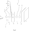
- the 1 shows a schematic side view of an embodiment of a mobile laboratory 1.
- the mobile laboratory 1 can be a vehicle, in particular a motor vehicle. Alternatively, the vehicle can also be a rail vehicle, a watercraft or an aircraft. The vehicle can in particular be a military vehicle. However, the vehicle can also be used in the civil sector.
- the mobile laboratory 1 comprises a laboratory room 2 in which a safety workbench 3, in particular a microbiological safety workbench, can be installed. The location of the safety workbench 3 can be changed with the aid of the mobile laboratory 1 .
- the safety workbench 3 includes a work area 4 for examining a sample 5.
- the sample 5 is preferably a microbiological sample.
- the working space 4 can be cuboid.
- the working space 4 can also be referred to as a glove box.
- the working space 4 comprises a front wall 6 which is at least partially transparent.
- a transfer sluice 7 for transferring the sample 5 into or out of the working area 4 can also be provided on the working area 4 .
- the sample 5 can be observed through the transparent front wall 6 .
- the transfer lock 7 can, as in the 2 shown, be provided on the side of the workspace 4. However, the transfer sluice 7 can also be provided at any other point in the working space 4 .
- the transfer lock 7 can be part of the working space 4 .
- any number of glove sockets 8 to 11 can be provided on the front wall 6 .
- four such glove sockets 8 to 11 can be provided.
- the number of glove sockets 8 to 11 is arbitrary. With the aid of the glove sockets 8 to 11, the sample 5 located in the working space 4 can be handled for examination.
- the safety workbench 3 also includes an operating area 12.
- the operating area 12 can be provided on the front of the work area 4, for example. However, the operating area 12 can also be a component that is separate from the workspace 4 . For example, the operating area 12 can be arranged below or above the workspace 4 .
- the safety workbench 3 also includes a measuring device 13 which is set up to detect an impact load acting on the work area 4 in at least one spatial direction x, y, z.
- the measuring device is preferred 13 set up to detect the impact load acting on the working space 4 in at least a first spatial direction or x-direction x, in a second spatial direction or y-direction y and in a third spatial direction or z-direction z.
- accelerations and decelerations acting in the three spatial directions x, y, z can be detected.
- a deceleration is to be understood as a negative acceleration.
- the measuring device 13 can, as in the 3 shown, include an acceleration sensor 14 for detecting the shock load.
- the acceleration sensor 14 can be set up to detect the acceleration in all three spatial directions x, y, z.
- the measuring device 13 can also have a first acceleration sensor 14, which is set up to detect the impact load in the first spatial direction x, a second acceleration sensor 15, which is set up to detect the impact load in the second spatial direction y, and a third acceleration sensor 16 include, which is set up to detect the shock load in the third spatial direction z.
- the measuring device 13 can also determine the shock load in the three spatial directions x, y, z using a position and time determination system.
- a data profile of the position and time determination system can include various vehicle data, such as a spring deflection of a wheel suspension over time, or terrain data that can be used to assess the impact loading occurring when the mobile laboratory 1 is moving.
- the safety workbench 3 can include a computing device 17 .
- the computing device 17 can be what is known as a data logger.
- a data logger is a process-controlled storage unit that records data at a specific rhythm via an interface and stores it on a storage medium 18 .
- the computing device 17 can include the measuring device 13 .
- the computing device 17 includes the storage medium 18, in which a maximum permissible impact load for each of the three spatial directions x, y and z is stored.
- the computing device 17 is set up to compare the impact load recorded with the aid of the measuring device 13 in each of the three spatial directions x, y, z with the maximum permissible impact load in the corresponding spatial direction x, y, z.
- the computing device 17 can comprise an evaluation unit 19, for example an integrated circuit, in particular a microchip.
- the safety workbench 3 also includes a signaling device 20 that can be controlled with the aid of the computing device 17.
- the signaling device 20 can be controlled by the computing device 17 in such a way that the signaling device 20 emits a signal as soon as the detected impact load for one of the spatial directions x, y, z exceeds the maximum permissible shock load for the respective spatial direction x, y, z.
- the signaling device 20 can be set up to emit an optical and/or an acoustic signal.
- the signaling device 20 can comprise, for example, a warning lamp and/or an acoustic signal generator.
- the signaling device 20 can also be a display device, such as a monitor, on which the detected impact load is displayed. Alternatively, a display device, such as a monitor, can also be provided in addition to the signal device 20 .
- the measuring device 13, the computing device 17 and the signaling device 20 form a measuring arrangement 21 of the safety workbench 3.
- the safety workbench 3 also includes a pressure sensor 22, with which a pressure prevailing in the working space 4 can be detected.
- the pressure sensor 22 can also be assigned to the measuring arrangement 21 .
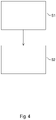
- the functionality of the safety workbench 3 is described below with reference to the Figures 1 to 3 as well as on the 4 , which shows a block diagram of an embodiment of a method for determining an impact load on the safety workbench 3.
- a defined negative pressure is first generated in the working area 4 of the safety workbench 3 .
- a supply air filter and an exhaust air filter of the safety cabinet 3 are preferably closed.
- a test movement, in particular a test drive is then carried out with the mobile laboratory 1 under conditions that are as extreme as possible. This test movement can take place, for example, as a test drive in the field, with driving maneuvers that are as extreme as possible being carried out in order to achieve large accelerations and decelerations in the three spatial directions x, y, z.
- test movement can also be carried out stationary on a simulator or a vibrating bench.
- pressure sensor 22 is used to measure and, for example, to record using computing device 17 .
- a dedicated computing device can also be assigned to the pressure sensor 22 . In this way, it is determined whether and to what extent the pressure in the working chamber 4 increases.
- the test movement is not carried out until an increased leakage rate, ie an increase in pressure, can be determined, but preferably only a test movement is carried out under extreme conditions that are not normally achieved in normal operation of the mobile laboratory 1 .
- the pressure in the working space 4 is monitored over a defined time interval, as in the test movement. If no significant increase in pressure is determined, it can be assumed that there is no leakage.
- the impact load acting on the workspace 4 of the safety workbench 3 recorded in at least one of the three spatial directions x, y, z.
- the shock load acting on the working space 4 is preferably recorded in all three spatial directions x, y, z.
- the measuring arrangement 21 is used for this.
- step S2 which can be carried out subsequently or at the same time as step S1
- the detected impact load is compared with the aid of the computing device 17 with the maximum permissible impact load acting in the corresponding spatial direction x, y, z.
- a corresponding signal can be output with the aid of the signaling device 20 when the detected impact load exceeds the maximum permissible impact load in at least one of the spatial directions x, y, z.
- step S2 If it is now determined in step S2 that the detected impact load exceeds the maximum permissible impact load, a corresponding signal is output with the aid of the signaling device 20, as mentioned above. Furthermore, as soon as the detected impact load exceeds the maximum permissible impact load in at least one spatial direction x, y, z, an installation check of the safety workbench 3 is carried out. For this purpose, as previously described, a negative pressure is generated in the working space 4, the change in which is measured and recorded over a defined period of time. If the negative pressure in the working area 4 does not change significantly, the safety workbench 3 can be put into operation.
- the safety bench 3 does not require a time-consuming and costly installation check after each change of location. The installation test is only necessary if the maximum permissible impact load in one of the three spatial directions x, y, z has actually been exceeded.
Landscapes
- Engineering & Computer Science (AREA)
- Mechanical Engineering (AREA)
- Forklifts And Lifting Vehicles (AREA)
- Investigating Strength Of Materials By Application Of Mechanical Stress (AREA)
Claims (15)
- Établi de sécurité (3) destiné à un laboratoire mobile (1), comprenant :un espace de travail (4) permettant d'examiner un échantillon (5), etun agencement de mesure (21) configuré pour détecter une charge d'impact agissant sur l'espace de travail (4) et pour la comparer à une charge d'impact maximale admissible.
- Établi de sécurité selon la revendication 1,
caractérisé par
un dispositif de signalisation (20) configuré pour émettre un signal dès que la charge d'impact détectée dépasse la charge d'impact maximale admissible. - Établi de sécurité selon la revendication 2,
caractérisé en ce que
le dispositif de signalisation (20) est configuré pour émettre un signal optique et/ou acoustique. - Établi de sécurité selon l'une des revendications 1 à 3,
caractérisé en ce que
l'agencement de mesure (21) comprend un dispositif de mesure (13) conçu pour détecter la charge d'impact agissant sur l'espace de travail (4), et une unité informatique (17) dans laquelle est mémorisée la charge d'impact maximale admissible et qui est configurée pour comparer la charge d'impact détectée au moyen du dispositif de mesure (13) à la charge d'impact maximale admissible. - Établi de sécurité selon la revendication 4,
caractérisé en ce que
le dispositif de mesure (13) est configuré pour détecter, dans trois directions spatiales différentes (x, y, z), la charge d'impact agissant sur l'espace de travail (4), une charge d'impact maximale admissible dans chaque direction spatiale (x, y, z) est mémorisée dans l'unité informatique (17), et l'unité informatique (17) commande un dispositif de signalisation (20) de sorte que ce dernier émette un signal dès que la charge d'impact détectée dépasse la charge d'impact maximale admissible dans au moins l'une direction des directions spatiales (x, y, z). - Établi de sécurité selon la revendication 4 ou la revendication 5,
caractérisé en ce que
le dispositif de mesure (13) comprend au moins un capteur d'accélération (14 - 16). - Établi de sécurité selon l'une des revendications 4 à 6,
caractérisé en ce que
le dispositif de mesure (13) est configuré pour détecter la charge d'impact agissant sur l'espace de travail (4) dans l'au moins une direction spatiale (x, y, z) pendant un changement de position de l'établi de sécurité (3). - Laboratoire mobile (1), en particulier un véhicule, comprenant un établi de sécurité (3) selon l'une des revendications 1 à 7.
- Procédé de détermination d'une charge d'impact d'un établi de sécurité (3) destiné à un laboratoire mobile (1), comprenant les étapes suivantes consistant à :détecter (S1) une charge d'impact agissant sur un espace de travail (4) de l'établi de sécurité (3), etcomparer (S2) la charge d'impact détectée à une charge d'impact maximale admissible.
- Procédé selon la revendication 9,
caractérisé en ce que
un signal est émis dès que la charge d'impact détectée dépasse la charge d'impact maximale admissible. - Procédé selon la revendication 9 ou la revendication 10,
caractérisé en ce que
la charge d'impact agissant sur l'espace de travail (4) est détectée dans trois directions spatiales différentes (x, y, z), la charge d'impact détectée dans chaque direction spatiale (x, y, z) est comparée à une charge d'impact maximale admissible attribuée à la direction spatiale respective (x, y, z), et un signal est émis dès que la charge d'impact détectée dépasse la charge d'impact maximale admissible dans au moins l'une des directions spatiales (x, y, z). - Procédé selon l'une des revendications 9 à 11,
caractérisé en ce que
un test d'installation est mis en oeuvre sur l'établi de sécurité (3) dès que la charge d'impact détectée dépasse la charge d'impact maximale admissible. - Procédé selon l'une des revendications 9 à 12,
caractérisé en ce que
la charge d'impact maximale admissible est déterminée pendant un déplacement test de l'établi de sécurité (3), en particulier pendant une conduite de test hors route, sur un banc vibrant ou sur un simulateur. - Procédé selon la revendication 13,
caractérisé en ce que
une pression négative est appliquée à l'espace de travail (4) pendant le déplacement test. - Procédé selon la revendication 13 ou la revendication 14,
caractérisé en ce que
un changement de pression dans l'espace de travail (4) est déterminé pendant le déplacement test et après le déplacement test.
Applications Claiming Priority (2)
| Application Number | Priority Date | Filing Date | Title |
|---|---|---|---|
| DE102016124495.3A DE102016124495A1 (de) | 2016-12-15 | 2016-12-15 | Sicherheitswerkbank, mobiles Labor und Verfahren |
| PCT/EP2017/082247 WO2018108824A1 (fr) | 2016-12-15 | 2017-12-11 | Poste de sécurité, laboratoire mobile et procédé |
Publications (2)
| Publication Number | Publication Date |
|---|---|
| EP3554768A1 EP3554768A1 (fr) | 2019-10-23 |
| EP3554768B1 true EP3554768B1 (fr) | 2022-06-08 |
Family
ID=60915479
Family Applications (1)
| Application Number | Title | Priority Date | Filing Date |
|---|---|---|---|
| EP17823061.1A Active EP3554768B1 (fr) | 2016-12-15 | 2017-12-11 | Poste de sécurité, laboratoire mobile et procédure |
Country Status (6)
| Country | Link |
|---|---|
| EP (1) | EP3554768B1 (fr) |
| AU (1) | AU2017375903B2 (fr) |
| CA (1) | CA3045255C (fr) |
| DE (1) | DE102016124495A1 (fr) |
| SA (1) | SA519401968B1 (fr) |
| WO (1) | WO2018108824A1 (fr) |
Families Citing this family (2)
| Publication number | Priority date | Publication date | Assignee | Title |
|---|---|---|---|---|
| DE102020000486B4 (de) | 2020-01-28 | 2021-09-09 | Bundesrepublik Deutschland, vertreten durch das Bundesministerium der Verteidigung, dieses vertreten durch das Bundesamt für Ausrüstung, Informationstechnik und Nutzung der Bundeswehr | Verlegbares Sicherheitscontainment mit einer Filterdichtsitzprüfeinrichtung |
| DE202020101570U1 (de) | 2020-03-23 | 2020-05-12 | Bachmayer Gmbh | Mobiles Labor |
Citations (1)
| Publication number | Priority date | Publication date | Assignee | Title |
|---|---|---|---|---|
| DE4139728C1 (fr) * | 1991-12-02 | 1993-01-21 | Smt & Hybrid Gmbh, O-8010 Dresden, De |
Family Cites Families (10)
| Publication number | Priority date | Publication date | Assignee | Title |
|---|---|---|---|---|
| JP2002029309A (ja) * | 2000-07-13 | 2002-01-29 | Fuji Electric Co Ltd | 輸送方法および変圧器 |
| CN2468676Y (zh) * | 2001-03-23 | 2002-01-02 | 浡全企业有限公司 | 安全机台装置 |
| DE10217904C1 (de) * | 2002-04-22 | 2003-10-02 | Kendro Lab Prod Gmbh | Sicherheitswerkbank mit Sicherheitsüberwachungssystem |
| DE102006053122B4 (de) * | 2006-11-10 | 2008-09-25 | Thermo Electron Led Gmbh | Sicherheitswerkbank mit in Abhängigkeit der Frontscheibenposition steuerbarer Gebläseleistung |
| DE102006060713B3 (de) * | 2006-12-21 | 2008-06-12 | Thermo Electron Led Gmbh | Sicherheitswerkbank und Verfahren zum Kalibrieren derselben |
| FR2917829B1 (fr) * | 2007-06-19 | 2009-10-09 | Terroirs & Conseils Sarl | Dispositif ambulant d'analyse des mouts de raisins et/ou des vins. |
| DE102009052013A1 (de) | 2009-11-05 | 2011-05-12 | Rheinmetall Landsysteme Gmbh | Sicherheitswerkbank |
| CN202847523U (zh) * | 2012-07-27 | 2013-04-03 | 苏州江南航天机电工业有限公司 | 一种移动式生物检验实验室 |
| WO2014049151A1 (fr) * | 2012-09-28 | 2014-04-03 | Promethera Biosciences | Dispositif mobile pour la préparation et la distribution de produits médicaux à base de cellules |
| DE102013000768B4 (de) * | 2013-01-18 | 2024-09-12 | Berner International Gmbh | Sicherheitswerkbank mit einer Anzeige des Betriebszustandes durch unterschiedliche Beleuchtung einer Frontscheibe und/oder von Lichtbändern |
-
2016
- 2016-12-15 DE DE102016124495.3A patent/DE102016124495A1/de not_active Withdrawn
-
2017
- 2017-12-11 WO PCT/EP2017/082247 patent/WO2018108824A1/fr not_active Ceased
- 2017-12-11 AU AU2017375903A patent/AU2017375903B2/en active Active
- 2017-12-11 EP EP17823061.1A patent/EP3554768B1/fr active Active
- 2017-12-11 CA CA3045255A patent/CA3045255C/fr active Active
-
2019
- 2019-06-10 SA SA519401968A patent/SA519401968B1/ar unknown
Patent Citations (1)
| Publication number | Priority date | Publication date | Assignee | Title |
|---|---|---|---|---|
| DE4139728C1 (fr) * | 1991-12-02 | 1993-01-21 | Smt & Hybrid Gmbh, O-8010 Dresden, De |
Also Published As
| Publication number | Publication date |
|---|---|
| WO2018108824A1 (fr) | 2018-06-21 |
| SA519401968B1 (ar) | 2022-09-08 |
| EP3554768A1 (fr) | 2019-10-23 |
| DE102016124495A1 (de) | 2018-06-21 |
| CA3045255C (fr) | 2022-01-04 |
| AU2017375903A1 (en) | 2019-06-20 |
| CA3045255A1 (fr) | 2018-06-21 |
| AU2017375903B2 (en) | 2020-08-06 |
Similar Documents
| Publication | Publication Date | Title |
|---|---|---|
| EP3102523B1 (fr) | Système et procédé de mesure pour vérifier le dispositif d'arrêt d'un ascenseur | |
| DE102014015910B4 (de) | Mobile Gasmesseinrichtung mit verbesserter Funktionssicherheit und Zuverlässigkeit | |
| DE102007038344A1 (de) | Integriertes Überwachungsverfahren für Nukleareinrichtungen und ein solches Verfahren verwendende Einrichtung | |
| DE102011053325A1 (de) | Prüfstand für die dynamische Überprüfung einer einzelnen Fahrwerkskomponente oder eines vollständigen Achssystems eines Kraftfahrzeugs, sowie Verfahren zum Überprüfen auf Selbigem | |
| DE102010040549A1 (de) | Kraftfahrzeug-Prüfgerät und Kraftfahrzeug-Prüfverfahren | |
| EP3145681A1 (fr) | Procédé permettant d'éviter à un robot de subir des collisions dans une station de travail | |
| DE112015005528T5 (de) | Kontrollgerät und Verfahren zur Bestimmung der Betriebsbereitschaft einer mit einem Druckmedium betriebenen Vorrichtung | |
| EP2101156B1 (fr) | Procédé et dispositif destinés à la surveillance de systèmes de réglage de châssis | |
| DE102012200194A1 (de) | Anordnung und Verfahren zur Baugruppenprüfung, insbesondere zur Achsdämpfungsprüfung, in Fahrzeugen | |
| EP3554768B1 (fr) | Poste de sécurité, laboratoire mobile et procédure | |
| DE102011088424A1 (de) | Prüfvorrichtung für einen Rollen-Prüfstand | |
| DE102008016763A1 (de) | Vorrichtung und Verfahren zum chromatographischen Nachweis einer Substanz | |
| DE102012000603A1 (de) | Verfahren zum Delektieren einer möglichen Beschädigung eines Kraftwagenbauteils | |
| DE102011078847A1 (de) | Verlagerungserkennungsverfahren und Verlagerungserkennungseinheit | |
| DE68921752T2 (de) | Methode und gerät zum testen von stossdämpfern und federungssystemen von fahrzeugen. | |
| EP3571008B1 (fr) | Procédé et dispositif permettant de déterminer et/ou de surveiller l'état d'un capot de protection | |
| DE102020000486A1 (de) | Verlegbares Sicherheitscontainment mit einer Filterdichtsitzprüfeinrichtung | |
| EP1746402A2 (fr) | Banc d'essai de simulation ainsi que procédé destinés à vérifier des composants de véhicules | |
| DE102015013555B4 (de) | Prüfstand zur Sitzvermessung | |
| DE102006043912B9 (de) | Pendelschlagwerk | |
| DE102018222539B4 (de) | Bremsenprüfstand, Verwendung und Betriebsverfahren für einen Bremsenprüfstand | |
| EP1004003B1 (fr) | Protection contre les chocs pour sondes de mesure de position | |
| DE10155667C1 (de) | Verfahren und Vorrichtung zum Abgleich von Kombisensoren mit einer Drehraten-Sensorkomponente und einer Beschleunigungs-Sensorkomponente | |
| DE102008048347A1 (de) | Kraftfahrzeugdiagnosesystem | |
| Božović et al. | Traffic safety impact factors related to changing the vehicles among drivers in closed systems |
Legal Events
| Date | Code | Title | Description |
|---|---|---|---|
| STAA | Information on the status of an ep patent application or granted ep patent |
Free format text: STATUS: UNKNOWN |
|
| STAA | Information on the status of an ep patent application or granted ep patent |
Free format text: STATUS: THE INTERNATIONAL PUBLICATION HAS BEEN MADE |
|
| PUAI | Public reference made under article 153(3) epc to a published international application that has entered the european phase |
Free format text: ORIGINAL CODE: 0009012 |
|
| STAA | Information on the status of an ep patent application or granted ep patent |
Free format text: STATUS: REQUEST FOR EXAMINATION WAS MADE |
|
| 17P | Request for examination filed |
Effective date: 20190710 |
|
| AK | Designated contracting states |
Kind code of ref document: A1 Designated state(s): AL AT BE BG CH CY CZ DE DK EE ES FI FR GB GR HR HU IE IS IT LI LT LU LV MC MK MT NL NO PL PT RO RS SE SI SK SM TR |
|
| AX | Request for extension of the european patent |
Extension state: BA ME |
|
| DAV | Request for validation of the european patent (deleted) | ||
| DAX | Request for extension of the european patent (deleted) | ||
| STAA | Information on the status of an ep patent application or granted ep patent |
Free format text: STATUS: EXAMINATION IS IN PROGRESS |
|
| 17Q | First examination report despatched |
Effective date: 20210531 |
|
| RIC1 | Information provided on ipc code assigned before grant |
Ipc: B08B 15/00 20060101ALI20211029BHEP Ipc: B08B 15/02 20060101ALI20211029BHEP Ipc: B25H 1/20 20060101AFI20211029BHEP |
|
| GRAP | Despatch of communication of intention to grant a patent |
Free format text: ORIGINAL CODE: EPIDOSNIGR1 |
|
| STAA | Information on the status of an ep patent application or granted ep patent |
Free format text: STATUS: GRANT OF PATENT IS INTENDED |
|
| INTG | Intention to grant announced |
Effective date: 20211221 |
|
| GRAS | Grant fee paid |
Free format text: ORIGINAL CODE: EPIDOSNIGR3 |
|
| GRAA | (expected) grant |
Free format text: ORIGINAL CODE: 0009210 |
|
| STAA | Information on the status of an ep patent application or granted ep patent |
Free format text: STATUS: THE PATENT HAS BEEN GRANTED |
|
| AK | Designated contracting states |
Kind code of ref document: B1 Designated state(s): AL AT BE BG CH CY CZ DE DK EE ES FI FR GB GR HR HU IE IS IT LI LT LU LV MC MK MT NL NO PL PT RO RS SE SI SK SM TR |
|
| RAP1 | Party data changed (applicant data changed or rights of an application transferred) |
Owner name: RHEINMETALL LANDSYSTEME GMBH |
|
| REG | Reference to a national code |
Ref country code: AT Ref legal event code: REF Ref document number: 1496598 Country of ref document: AT Kind code of ref document: T Effective date: 20220615 Ref country code: CH Ref legal event code: EP |
|
| REG | Reference to a national code |
Ref country code: DE Ref legal event code: R096 Ref document number: 502017013302 Country of ref document: DE |
|
| REG | Reference to a national code |
Ref country code: IE Ref legal event code: FG4D Free format text: LANGUAGE OF EP DOCUMENT: GERMAN |
|
| REG | Reference to a national code |
Ref country code: NO Ref legal event code: T2 Effective date: 20220608 |
|
| REG | Reference to a national code |
Ref country code: FI Ref legal event code: FGE |
|
| REG | Reference to a national code |
Ref country code: NL Ref legal event code: FP |
|
| REG | Reference to a national code |
Ref country code: SE Ref legal event code: TRGR |
|
| REG | Reference to a national code |
Ref country code: LT Ref legal event code: MG9D |
|
| PG25 | Lapsed in a contracting state [announced via postgrant information from national office to epo] |
Ref country code: LT Free format text: LAPSE BECAUSE OF FAILURE TO SUBMIT A TRANSLATION OF THE DESCRIPTION OR TO PAY THE FEE WITHIN THE PRESCRIBED TIME-LIMIT Effective date: 20220608 Ref country code: HR Free format text: LAPSE BECAUSE OF FAILURE TO SUBMIT A TRANSLATION OF THE DESCRIPTION OR TO PAY THE FEE WITHIN THE PRESCRIBED TIME-LIMIT Effective date: 20220608 Ref country code: GR Free format text: LAPSE BECAUSE OF FAILURE TO SUBMIT A TRANSLATION OF THE DESCRIPTION OR TO PAY THE FEE WITHIN THE PRESCRIBED TIME-LIMIT Effective date: 20220909 Ref country code: ES Free format text: LAPSE BECAUSE OF FAILURE TO SUBMIT A TRANSLATION OF THE DESCRIPTION OR TO PAY THE FEE WITHIN THE PRESCRIBED TIME-LIMIT Effective date: 20220608 Ref country code: BG Free format text: LAPSE BECAUSE OF FAILURE TO SUBMIT A TRANSLATION OF THE DESCRIPTION OR TO PAY THE FEE WITHIN THE PRESCRIBED TIME-LIMIT Effective date: 20220908 |
|
| PG25 | Lapsed in a contracting state [announced via postgrant information from national office to epo] |
Ref country code: RS Free format text: LAPSE BECAUSE OF FAILURE TO SUBMIT A TRANSLATION OF THE DESCRIPTION OR TO PAY THE FEE WITHIN THE PRESCRIBED TIME-LIMIT Effective date: 20220608 Ref country code: LV Free format text: LAPSE BECAUSE OF FAILURE TO SUBMIT A TRANSLATION OF THE DESCRIPTION OR TO PAY THE FEE WITHIN THE PRESCRIBED TIME-LIMIT Effective date: 20220608 |
|
| PG25 | Lapsed in a contracting state [announced via postgrant information from national office to epo] |
Ref country code: SM Free format text: LAPSE BECAUSE OF FAILURE TO SUBMIT A TRANSLATION OF THE DESCRIPTION OR TO PAY THE FEE WITHIN THE PRESCRIBED TIME-LIMIT Effective date: 20220608 Ref country code: SK Free format text: LAPSE BECAUSE OF FAILURE TO SUBMIT A TRANSLATION OF THE DESCRIPTION OR TO PAY THE FEE WITHIN THE PRESCRIBED TIME-LIMIT Effective date: 20220608 Ref country code: RO Free format text: LAPSE BECAUSE OF FAILURE TO SUBMIT A TRANSLATION OF THE DESCRIPTION OR TO PAY THE FEE WITHIN THE PRESCRIBED TIME-LIMIT Effective date: 20220608 Ref country code: PT Free format text: LAPSE BECAUSE OF FAILURE TO SUBMIT A TRANSLATION OF THE DESCRIPTION OR TO PAY THE FEE WITHIN THE PRESCRIBED TIME-LIMIT Effective date: 20221010 Ref country code: EE Free format text: LAPSE BECAUSE OF FAILURE TO SUBMIT A TRANSLATION OF THE DESCRIPTION OR TO PAY THE FEE WITHIN THE PRESCRIBED TIME-LIMIT Effective date: 20220608 Ref country code: CZ Free format text: LAPSE BECAUSE OF FAILURE TO SUBMIT A TRANSLATION OF THE DESCRIPTION OR TO PAY THE FEE WITHIN THE PRESCRIBED TIME-LIMIT Effective date: 20220608 |
|
| PG25 | Lapsed in a contracting state [announced via postgrant information from national office to epo] |
Ref country code: PL Free format text: LAPSE BECAUSE OF FAILURE TO SUBMIT A TRANSLATION OF THE DESCRIPTION OR TO PAY THE FEE WITHIN THE PRESCRIBED TIME-LIMIT Effective date: 20220608 Ref country code: IS Free format text: LAPSE BECAUSE OF FAILURE TO SUBMIT A TRANSLATION OF THE DESCRIPTION OR TO PAY THE FEE WITHIN THE PRESCRIBED TIME-LIMIT Effective date: 20221008 |
|
| REG | Reference to a national code |
Ref country code: DE Ref legal event code: R097 Ref document number: 502017013302 Country of ref document: DE |
|
| PG25 | Lapsed in a contracting state [announced via postgrant information from national office to epo] |
Ref country code: AL Free format text: LAPSE BECAUSE OF FAILURE TO SUBMIT A TRANSLATION OF THE DESCRIPTION OR TO PAY THE FEE WITHIN THE PRESCRIBED TIME-LIMIT Effective date: 20220608 |
|
| PLBE | No opposition filed within time limit |
Free format text: ORIGINAL CODE: 0009261 |
|
| STAA | Information on the status of an ep patent application or granted ep patent |
Free format text: STATUS: NO OPPOSITION FILED WITHIN TIME LIMIT |
|
| PG25 | Lapsed in a contracting state [announced via postgrant information from national office to epo] |
Ref country code: DK Free format text: LAPSE BECAUSE OF FAILURE TO SUBMIT A TRANSLATION OF THE DESCRIPTION OR TO PAY THE FEE WITHIN THE PRESCRIBED TIME-LIMIT Effective date: 20220608 |
|
| 26N | No opposition filed |
Effective date: 20230310 |
|
| PG25 | Lapsed in a contracting state [announced via postgrant information from national office to epo] |
Ref country code: SI Free format text: LAPSE BECAUSE OF FAILURE TO SUBMIT A TRANSLATION OF THE DESCRIPTION OR TO PAY THE FEE WITHIN THE PRESCRIBED TIME-LIMIT Effective date: 20220608 |
|
| REG | Reference to a national code |
Ref country code: BE Ref legal event code: MM Effective date: 20221231 |
|
| PG25 | Lapsed in a contracting state [announced via postgrant information from national office to epo] |
Ref country code: LU Free format text: LAPSE BECAUSE OF NON-PAYMENT OF DUE FEES Effective date: 20221211 |
|
| PG25 | Lapsed in a contracting state [announced via postgrant information from national office to epo] |
Ref country code: IE Free format text: LAPSE BECAUSE OF NON-PAYMENT OF DUE FEES Effective date: 20221211 |
|
| PG25 | Lapsed in a contracting state [announced via postgrant information from national office to epo] |
Ref country code: BE Free format text: LAPSE BECAUSE OF NON-PAYMENT OF DUE FEES Effective date: 20221231 |
|
| PG25 | Lapsed in a contracting state [announced via postgrant information from national office to epo] |
Ref country code: IT Free format text: LAPSE BECAUSE OF FAILURE TO SUBMIT A TRANSLATION OF THE DESCRIPTION OR TO PAY THE FEE WITHIN THE PRESCRIBED TIME-LIMIT Effective date: 20220608 |
|
| PG25 | Lapsed in a contracting state [announced via postgrant information from national office to epo] |
Ref country code: HU Free format text: LAPSE BECAUSE OF FAILURE TO SUBMIT A TRANSLATION OF THE DESCRIPTION OR TO PAY THE FEE WITHIN THE PRESCRIBED TIME-LIMIT; INVALID AB INITIO Effective date: 20171211 |
|
| PG25 | Lapsed in a contracting state [announced via postgrant information from national office to epo] |
Ref country code: CY Free format text: LAPSE BECAUSE OF FAILURE TO SUBMIT A TRANSLATION OF THE DESCRIPTION OR TO PAY THE FEE WITHIN THE PRESCRIBED TIME-LIMIT Effective date: 20220608 |
|
| PG25 | Lapsed in a contracting state [announced via postgrant information from national office to epo] |
Ref country code: MK Free format text: LAPSE BECAUSE OF FAILURE TO SUBMIT A TRANSLATION OF THE DESCRIPTION OR TO PAY THE FEE WITHIN THE PRESCRIBED TIME-LIMIT Effective date: 20220608 |
|
| PG25 | Lapsed in a contracting state [announced via postgrant information from national office to epo] |
Ref country code: MC Free format text: LAPSE BECAUSE OF FAILURE TO SUBMIT A TRANSLATION OF THE DESCRIPTION OR TO PAY THE FEE WITHIN THE PRESCRIBED TIME-LIMIT Effective date: 20220608 |
|
| PG25 | Lapsed in a contracting state [announced via postgrant information from national office to epo] |
Ref country code: MC Free format text: LAPSE BECAUSE OF FAILURE TO SUBMIT A TRANSLATION OF THE DESCRIPTION OR TO PAY THE FEE WITHIN THE PRESCRIBED TIME-LIMIT Effective date: 20220608 |
|
| PG25 | Lapsed in a contracting state [announced via postgrant information from national office to epo] |
Ref country code: MT Free format text: LAPSE BECAUSE OF FAILURE TO SUBMIT A TRANSLATION OF THE DESCRIPTION OR TO PAY THE FEE WITHIN THE PRESCRIBED TIME-LIMIT Effective date: 20220608 |
|
| PG25 | Lapsed in a contracting state [announced via postgrant information from national office to epo] |
Ref country code: BG Free format text: LAPSE BECAUSE OF FAILURE TO SUBMIT A TRANSLATION OF THE DESCRIPTION OR TO PAY THE FEE WITHIN THE PRESCRIBED TIME-LIMIT Effective date: 20220608 |
|
| PG25 | Lapsed in a contracting state [announced via postgrant information from national office to epo] |
Ref country code: BG Free format text: LAPSE BECAUSE OF FAILURE TO SUBMIT A TRANSLATION OF THE DESCRIPTION OR TO PAY THE FEE WITHIN THE PRESCRIBED TIME-LIMIT Effective date: 20220608 |
|
| PGFP | Annual fee paid to national office [announced via postgrant information from national office to epo] |
Ref country code: DE Payment date: 20241210 Year of fee payment: 8 |
|
| PGFP | Annual fee paid to national office [announced via postgrant information from national office to epo] |
Ref country code: NO Payment date: 20241227 Year of fee payment: 8 |
|
| PGFP | Annual fee paid to national office [announced via postgrant information from national office to epo] |
Ref country code: NL Payment date: 20241219 Year of fee payment: 8 Ref country code: FI Payment date: 20241219 Year of fee payment: 8 |
|
| PGFP | Annual fee paid to national office [announced via postgrant information from national office to epo] |
Ref country code: GB Payment date: 20241226 Year of fee payment: 8 |
|
| PGFP | Annual fee paid to national office [announced via postgrant information from national office to epo] |
Ref country code: FR Payment date: 20241224 Year of fee payment: 8 |
|
| PGFP | Annual fee paid to national office [announced via postgrant information from national office to epo] |
Ref country code: AT Payment date: 20241220 Year of fee payment: 8 |
|
| PGFP | Annual fee paid to national office [announced via postgrant information from national office to epo] |
Ref country code: SE Payment date: 20241219 Year of fee payment: 8 |
|
| PGFP | Annual fee paid to national office [announced via postgrant information from national office to epo] |
Ref country code: TR Payment date: 20241202 Year of fee payment: 8 |
|
| PGFP | Annual fee paid to national office [announced via postgrant information from national office to epo] |
Ref country code: CH Payment date: 20250101 Year of fee payment: 8 |