EP3554756B1 - Verfahren zur herstellung einer transmitiven optik - Google Patents
Verfahren zur herstellung einer transmitiven optik Download PDFInfo
- Publication number
- EP3554756B1 EP3554756B1 EP17801008.8A EP17801008A EP3554756B1 EP 3554756 B1 EP3554756 B1 EP 3554756B1 EP 17801008 A EP17801008 A EP 17801008A EP 3554756 B1 EP3554756 B1 EP 3554756B1
- Authority
- EP
- European Patent Office
- Prior art keywords
- laser
- ablation
- blank
- lens
- polishing
- Prior art date
- Legal status (The legal status is an assumption and is not a legal conclusion. Google has not performed a legal analysis and makes no representation as to the accuracy of the status listed.)
- Active
Links
Images


Classifications
-
- B—PERFORMING OPERATIONS; TRANSPORTING
- B23—MACHINE TOOLS; METAL-WORKING NOT OTHERWISE PROVIDED FOR
- B23K—SOLDERING OR UNSOLDERING; WELDING; CLADDING OR PLATING BY SOLDERING OR WELDING; CUTTING BY APPLYING HEAT LOCALLY, e.g. FLAME CUTTING; WORKING BY LASER BEAM
- B23K26/00—Working by laser beam, e.g. welding, cutting or boring
- B23K26/36—Removing material
-
- B—PERFORMING OPERATIONS; TRANSPORTING
- B23—MACHINE TOOLS; METAL-WORKING NOT OTHERWISE PROVIDED FOR
- B23K—SOLDERING OR UNSOLDERING; WELDING; CLADDING OR PLATING BY SOLDERING OR WELDING; CUTTING BY APPLYING HEAT LOCALLY, e.g. FLAME CUTTING; WORKING BY LASER BEAM
- B23K26/00—Working by laser beam, e.g. welding, cutting or boring
- B23K26/02—Positioning or observing the workpiece, e.g. with respect to the point of impact; Aligning, aiming or focusing the laser beam
- B23K26/06—Shaping the laser beam, e.g. by masks or multi-focusing
- B23K26/062—Shaping the laser beam, e.g. by masks or multi-focusing by direct control of the laser beam
- B23K26/0622—Shaping the laser beam, e.g. by masks or multi-focusing by direct control of the laser beam by shaping pulses
- B23K26/0624—Shaping the laser beam, e.g. by masks or multi-focusing by direct control of the laser beam by shaping pulses using ultrashort pulses, i.e. pulses of 1 ns or less
-
- A—HUMAN NECESSITIES
- A61—MEDICAL OR VETERINARY SCIENCE; HYGIENE
- A61F—FILTERS IMPLANTABLE INTO BLOOD VESSELS; PROSTHESES; DEVICES PROVIDING PATENCY TO, OR PREVENTING COLLAPSING OF, TUBULAR STRUCTURES OF THE BODY, e.g. STENTS; ORTHOPAEDIC, NURSING OR CONTRACEPTIVE DEVICES; FOMENTATION; TREATMENT OR PROTECTION OF EYES OR EARS; BANDAGES, DRESSINGS OR ABSORBENT PADS; FIRST-AID KITS
- A61F2/00—Filters implantable into blood vessels; Prostheses, i.e. artificial substitutes or replacements for parts of the body; Appliances for connecting them with the body; Devices providing patency to, or preventing collapsing of, tubular structures of the body, e.g. stents
- A61F2/02—Prostheses implantable into the body
- A61F2/14—Eye parts, e.g. lenses or corneal implants; Artificial eyes
- A61F2/16—Intraocular lenses
- A61F2/1613—Intraocular lenses having special lens configurations, e.g. multipart lenses; having particular optical properties, e.g. pseudo-accommodative lenses, lenses having aberration corrections, diffractive lenses, lenses for variably absorbing electromagnetic radiation, lenses having variable focus
- A61F2/1616—Pseudo-accommodative, e.g. multifocal or enabling monovision
- A61F2/1618—Multifocal lenses
-
- B—PERFORMING OPERATIONS; TRANSPORTING
- B22—CASTING; POWDER METALLURGY
- B22F—WORKING METALLIC POWDER; MANUFACTURE OF ARTICLES FROM METALLIC POWDER; MAKING METALLIC POWDER; APPARATUS OR DEVICES SPECIALLY ADAPTED FOR METALLIC POWDER
- B22F10/00—Additive manufacturing of workpieces or articles from metallic powder
- B22F10/60—Treatment of workpieces or articles after build-up
- B22F10/66—Treatment of workpieces or articles after build-up by mechanical means
-
- B—PERFORMING OPERATIONS; TRANSPORTING
- B23—MACHINE TOOLS; METAL-WORKING NOT OTHERWISE PROVIDED FOR
- B23K—SOLDERING OR UNSOLDERING; WELDING; CLADDING OR PLATING BY SOLDERING OR WELDING; CUTTING BY APPLYING HEAT LOCALLY, e.g. FLAME CUTTING; WORKING BY LASER BEAM
- B23K26/00—Working by laser beam, e.g. welding, cutting or boring
- B23K26/02—Positioning or observing the workpiece, e.g. with respect to the point of impact; Aligning, aiming or focusing the laser beam
- B23K26/03—Observing, e.g. monitoring, the workpiece
- B23K26/034—Observing the temperature of the workpiece
-
- B—PERFORMING OPERATIONS; TRANSPORTING
- B23—MACHINE TOOLS; METAL-WORKING NOT OTHERWISE PROVIDED FOR
- B23K—SOLDERING OR UNSOLDERING; WELDING; CLADDING OR PLATING BY SOLDERING OR WELDING; CUTTING BY APPLYING HEAT LOCALLY, e.g. FLAME CUTTING; WORKING BY LASER BEAM
- B23K26/00—Working by laser beam, e.g. welding, cutting or boring
- B23K26/08—Devices involving relative movement between laser beam and workpiece
- B23K26/082—Scanning systems, i.e. devices involving movement of the laser beam relative to the laser head
-
- B—PERFORMING OPERATIONS; TRANSPORTING
- B23—MACHINE TOOLS; METAL-WORKING NOT OTHERWISE PROVIDED FOR
- B23K—SOLDERING OR UNSOLDERING; WELDING; CLADDING OR PLATING BY SOLDERING OR WELDING; CUTTING BY APPLYING HEAT LOCALLY, e.g. FLAME CUTTING; WORKING BY LASER BEAM
- B23K26/00—Working by laser beam, e.g. welding, cutting or boring
- B23K26/352—Working by laser beam, e.g. welding, cutting or boring for surface treatment
- B23K26/3568—Modifying rugosity
- B23K26/3576—Diminishing rugosity, e.g. by grinding, polishing or smoothing
-
- B—PERFORMING OPERATIONS; TRANSPORTING
- B23—MACHINE TOOLS; METAL-WORKING NOT OTHERWISE PROVIDED FOR
- B23K—SOLDERING OR UNSOLDERING; WELDING; CLADDING OR PLATING BY SOLDERING OR WELDING; CUTTING BY APPLYING HEAT LOCALLY, e.g. FLAME CUTTING; WORKING BY LASER BEAM
- B23K26/00—Working by laser beam, e.g. welding, cutting or boring
- B23K26/36—Removing material
- B23K26/40—Removing material taking account of the properties of the material involved
- B23K26/402—Removing material taking account of the properties of the material involved involving non-metallic material, e.g. isolators
-
- B—PERFORMING OPERATIONS; TRANSPORTING
- B29—WORKING OF PLASTICS; WORKING OF SUBSTANCES IN A PLASTIC STATE IN GENERAL
- B29C—SHAPING OR JOINING OF PLASTICS; SHAPING OF MATERIAL IN A PLASTIC STATE, NOT OTHERWISE PROVIDED FOR; AFTER-TREATMENT OF THE SHAPED PRODUCTS, e.g. REPAIRING
- B29C45/00—Injection moulding, i.e. forcing the required volume of moulding material through a nozzle into a closed mould; Apparatus therefor
- B29C45/0053—Injection moulding, i.e. forcing the required volume of moulding material through a nozzle into a closed mould; Apparatus therefor combined with a final operation, e.g. shaping
- B29C45/0055—Shaping
-
- B—PERFORMING OPERATIONS; TRANSPORTING
- B29—WORKING OF PLASTICS; WORKING OF SUBSTANCES IN A PLASTIC STATE IN GENERAL
- B29C—SHAPING OR JOINING OF PLASTICS; SHAPING OF MATERIAL IN A PLASTIC STATE, NOT OTHERWISE PROVIDED FOR; AFTER-TREATMENT OF THE SHAPED PRODUCTS, e.g. REPAIRING
- B29C45/00—Injection moulding, i.e. forcing the required volume of moulding material through a nozzle into a closed mould; Apparatus therefor
- B29C45/16—Making multilayered or multicoloured articles
-
- B—PERFORMING OPERATIONS; TRANSPORTING
- B29—WORKING OF PLASTICS; WORKING OF SUBSTANCES IN A PLASTIC STATE IN GENERAL
- B29C—SHAPING OR JOINING OF PLASTICS; SHAPING OF MATERIAL IN A PLASTIC STATE, NOT OTHERWISE PROVIDED FOR; AFTER-TREATMENT OF THE SHAPED PRODUCTS, e.g. REPAIRING
- B29C45/00—Injection moulding, i.e. forcing the required volume of moulding material through a nozzle into a closed mould; Apparatus therefor
- B29C45/17—Component parts, details or accessories; Auxiliary operations
- B29C45/76—Measuring, controlling or regulating
- B29C45/77—Measuring, controlling or regulating of velocity or pressure of moulding material
-
- B—PERFORMING OPERATIONS; TRANSPORTING
- B29—WORKING OF PLASTICS; WORKING OF SUBSTANCES IN A PLASTIC STATE IN GENERAL
- B29D—PRODUCING PARTICULAR ARTICLES FROM PLASTICS OR FROM SUBSTANCES IN A PLASTIC STATE
- B29D11/00—Producing optical elements, e.g. lenses or prisms
- B29D11/00009—Production of simple or compound lenses
- B29D11/00432—Auxiliary operations, e.g. machines for filling the moulds
- B29D11/00451—Changing a shape by remelting
-
- B—PERFORMING OPERATIONS; TRANSPORTING
- B29—WORKING OF PLASTICS; WORKING OF SUBSTANCES IN A PLASTIC STATE IN GENERAL
- B29D—PRODUCING PARTICULAR ARTICLES FROM PLASTICS OR FROM SUBSTANCES IN A PLASTIC STATE
- B29D11/00—Producing optical elements, e.g. lenses or prisms
- B29D11/00932—Combined cutting and grinding thereof
-
- B—PERFORMING OPERATIONS; TRANSPORTING
- B29—WORKING OF PLASTICS; WORKING OF SUBSTANCES IN A PLASTIC STATE IN GENERAL
- B29D—PRODUCING PARTICULAR ARTICLES FROM PLASTICS OR FROM SUBSTANCES IN A PLASTIC STATE
- B29D11/00—Producing optical elements, e.g. lenses or prisms
- B29D11/00951—Measuring, controlling or regulating
-
- B—PERFORMING OPERATIONS; TRANSPORTING
- B29—WORKING OF PLASTICS; WORKING OF SUBSTANCES IN A PLASTIC STATE IN GENERAL
- B29D—PRODUCING PARTICULAR ARTICLES FROM PLASTICS OR FROM SUBSTANCES IN A PLASTIC STATE
- B29D11/00—Producing optical elements, e.g. lenses or prisms
- B29D11/02—Artificial eyes from organic plastic material
- B29D11/023—Implants for natural eyes
-
- B—PERFORMING OPERATIONS; TRANSPORTING
- B33—ADDITIVE MANUFACTURING TECHNOLOGY
- B33Y—ADDITIVE MANUFACTURING, i.e. MANUFACTURING OF THREE-DIMENSIONAL [3D] OBJECTS BY ADDITIVE DEPOSITION, ADDITIVE AGGLOMERATION OR ADDITIVE LAYERING, e.g. BY 3D PRINTING, STEREOLITHOGRAPHY OR SELECTIVE LASER SINTERING
- B33Y80/00—Products made by additive manufacturing
-
- G—PHYSICS
- G02—OPTICS
- G02B—OPTICAL ELEMENTS, SYSTEMS OR APPARATUS
- G02B1/00—Optical elements characterised by the material of which they are made; Optical coatings for optical elements
- G02B1/04—Optical elements characterised by the material of which they are made; Optical coatings for optical elements made of organic materials, e.g. plastics
-
- G—PHYSICS
- G02—OPTICS
- G02C—SPECTACLES; SUNGLASSES OR GOGGLES INSOFAR AS THEY HAVE THE SAME FEATURES AS SPECTACLES; CONTACT LENSES
- G02C7/00—Optical parts
- G02C7/02—Lenses; Lens systems ; Methods of designing lenses
-
- G—PHYSICS
- G02—OPTICS
- G02C—SPECTACLES; SUNGLASSES OR GOGGLES INSOFAR AS THEY HAVE THE SAME FEATURES AS SPECTACLES; CONTACT LENSES
- G02C7/00—Optical parts
- G02C7/02—Lenses; Lens systems ; Methods of designing lenses
- G02C7/06—Lenses; Lens systems ; Methods of designing lenses bifocal; multifocal ; progressive
-
- A—HUMAN NECESSITIES
- A61—MEDICAL OR VETERINARY SCIENCE; HYGIENE
- A61F—FILTERS IMPLANTABLE INTO BLOOD VESSELS; PROSTHESES; DEVICES PROVIDING PATENCY TO, OR PREVENTING COLLAPSING OF, TUBULAR STRUCTURES OF THE BODY, e.g. STENTS; ORTHOPAEDIC, NURSING OR CONTRACEPTIVE DEVICES; FOMENTATION; TREATMENT OR PROTECTION OF EYES OR EARS; BANDAGES, DRESSINGS OR ABSORBENT PADS; FIRST-AID KITS
- A61F2240/00—Manufacturing or designing of prostheses classified in groups A61F2/00 - A61F2/26 or A61F2/82 or A61F9/00 or A61F11/00 or subgroups thereof
- A61F2240/001—Designing or manufacturing processes
- A61F2240/002—Designing or making customized prostheses
-
- B—PERFORMING OPERATIONS; TRANSPORTING
- B22—CASTING; POWDER METALLURGY
- B22F—WORKING METALLIC POWDER; MANUFACTURE OF ARTICLES FROM METALLIC POWDER; MAKING METALLIC POWDER; APPARATUS OR DEVICES SPECIALLY ADAPTED FOR METALLIC POWDER
- B22F10/00—Additive manufacturing of workpieces or articles from metallic powder
- B22F10/20—Direct sintering or melting
-
- B—PERFORMING OPERATIONS; TRANSPORTING
- B23—MACHINE TOOLS; METAL-WORKING NOT OTHERWISE PROVIDED FOR
- B23K—SOLDERING OR UNSOLDERING; WELDING; CLADDING OR PLATING BY SOLDERING OR WELDING; CUTTING BY APPLYING HEAT LOCALLY, e.g. FLAME CUTTING; WORKING BY LASER BEAM
- B23K2103/00—Materials to be soldered, welded or cut
- B23K2103/30—Organic materials
- B23K2103/42—Plastics other than composite materials
-
- B—PERFORMING OPERATIONS; TRANSPORTING
- B29—WORKING OF PLASTICS; WORKING OF SUBSTANCES IN A PLASTIC STATE IN GENERAL
- B29C—SHAPING OR JOINING OF PLASTICS; SHAPING OF MATERIAL IN A PLASTIC STATE, NOT OTHERWISE PROVIDED FOR; AFTER-TREATMENT OF THE SHAPED PRODUCTS, e.g. REPAIRING
- B29C2945/00—Indexing scheme relating to injection moulding, i.e. forcing the required volume of moulding material through a nozzle into a closed mould
- B29C2945/76—Measuring, controlling or regulating
- B29C2945/76494—Controlled parameter
- B29C2945/76498—Pressure
-
- B—PERFORMING OPERATIONS; TRANSPORTING
- B29—WORKING OF PLASTICS; WORKING OF SUBSTANCES IN A PLASTIC STATE IN GENERAL
- B29K—INDEXING SCHEME ASSOCIATED WITH SUBCLASSES B29B, B29C OR B29D, RELATING TO MOULDING MATERIALS OR TO MATERIALS FOR MOULDS, REINFORCEMENTS, FILLERS OR PREFORMED PARTS, e.g. INSERTS
- B29K2033/00—Use of polymers of unsaturated acids or derivatives thereof as moulding material
- B29K2033/04—Polymers of esters
-
- B—PERFORMING OPERATIONS; TRANSPORTING
- B29—WORKING OF PLASTICS; WORKING OF SUBSTANCES IN A PLASTIC STATE IN GENERAL
- B29K—INDEXING SCHEME ASSOCIATED WITH SUBCLASSES B29B, B29C OR B29D, RELATING TO MOULDING MATERIALS OR TO MATERIALS FOR MOULDS, REINFORCEMENTS, FILLERS OR PREFORMED PARTS, e.g. INSERTS
- B29K2995/00—Properties of moulding materials, reinforcements, fillers, preformed parts or moulds
- B29K2995/0018—Properties of moulding materials, reinforcements, fillers, preformed parts or moulds having particular optical properties, e.g. fluorescent or phosphorescent
-
- B—PERFORMING OPERATIONS; TRANSPORTING
- B29—WORKING OF PLASTICS; WORKING OF SUBSTANCES IN A PLASTIC STATE IN GENERAL
- B29L—INDEXING SCHEME ASSOCIATED WITH SUBCLASS B29C, RELATING TO PARTICULAR ARTICLES
- B29L2011/00—Optical elements, e.g. lenses, prisms
- B29L2011/0008—Artificial eyes
-
- B—PERFORMING OPERATIONS; TRANSPORTING
- B29—WORKING OF PLASTICS; WORKING OF SUBSTANCES IN A PLASTIC STATE IN GENERAL
- B29L—INDEXING SCHEME ASSOCIATED WITH SUBCLASS B29C, RELATING TO PARTICULAR ARTICLES
- B29L2011/00—Optical elements, e.g. lenses, prisms
- B29L2011/0016—Lenses
-
- B—PERFORMING OPERATIONS; TRANSPORTING
- B33—ADDITIVE MANUFACTURING TECHNOLOGY
- B33Y—ADDITIVE MANUFACTURING, i.e. MANUFACTURING OF THREE-DIMENSIONAL [3D] OBJECTS BY ADDITIVE DEPOSITION, ADDITIVE AGGLOMERATION OR ADDITIVE LAYERING, e.g. BY 3D PRINTING, STEREOLITHOGRAPHY OR SELECTIVE LASER SINTERING
- B33Y10/00—Processes of additive manufacturing
-
- G—PHYSICS
- G02—OPTICS
- G02B—OPTICAL ELEMENTS, SYSTEMS OR APPARATUS
- G02B1/00—Optical elements characterised by the material of which they are made; Optical coatings for optical elements
- G02B1/04—Optical elements characterised by the material of which they are made; Optical coatings for optical elements made of organic materials, e.g. plastics
- G02B1/041—Lenses
-
- Y—GENERAL TAGGING OF NEW TECHNOLOGICAL DEVELOPMENTS; GENERAL TAGGING OF CROSS-SECTIONAL TECHNOLOGIES SPANNING OVER SEVERAL SECTIONS OF THE IPC; TECHNICAL SUBJECTS COVERED BY FORMER USPC CROSS-REFERENCE ART COLLECTIONS [XRACs] AND DIGESTS
- Y02—TECHNOLOGIES OR APPLICATIONS FOR MITIGATION OR ADAPTATION AGAINST CLIMATE CHANGE
- Y02P—CLIMATE CHANGE MITIGATION TECHNOLOGIES IN THE PRODUCTION OR PROCESSING OF GOODS
- Y02P10/00—Technologies related to metal processing
- Y02P10/25—Process efficiency
Definitions
- the invention relates to a method for producing transmissive optics from a blank.
- Transmissive optics are usually a lens.
- the invention relates in particular to the production of an intraocular lens, a contact lens, a refractive implant or a spectacle lens. Furthermore, the invention also relates to the processing of optical surfaces that are partly mirrored and partly transparent to radiation.
- the WO 2012/119761 A1 relates to a method for producing optical elements by processing with energetic radiation, preferably with laser radiation.
- quartz glass blanks are first treated by rough removal and then by polishing and fine removal. This iterative process with several process steps is particularly suitable for hard materials such as glass or steel.
- the DE 10 2007 058 105 A1 describes a method for producing transmissive optics using an ablation laser.
- the material is not removed from a blank using a laser, but rather using a removal agent that is supplied separately to the surface to be processed using an evaporator.
- material removal is achieved with the removal agent and the laser does not act on the surface of the blank but rather on the removal agent, which absorbs the laser radiation as a vapor phase or in a condensed liquid phase between the laser and the blank.
- the pulse durations of less than 500 fs specified in this application refer to the laser radiation that hits the vaporous or liquid removal agent and not to a laser beam that leads to material removal from the blank.
- Such processes are suitable for particularly hard materials.
- the US 5,143,660 A describes an injection molding process for producing plastic lenses. Special holes are formed in the lens that are used to absorb liquids, especially medications.
- the WO 2015 165435 A1 (Base for the preamble of claim 1) shows a generic method, which, however, cannot be used for industrial use.
- the invention is therefore based on the object of presenting a generic method that enables rapid, cost-effective production.
- the extremely short pulse duration of the ablation laser means that the material of the blank that evaporates during the pulse does not hinder the energy input after evaporation and after each pulse, within the short interruption between two pulses, the vapor can largely escape from the processing zone Laser can be directed to another processing zone. This enables precise surface processing, in which small craters that are very close together can be created on the surface of the blank.
- the short pulse duration means that there is almost no interaction between the melt or the material of the blank evaporating under laser radiation.
- the material removal is achieved through direct evaporation and this means that the treated material is hardly damaged.
- the ultra-short laser pulses with durations ranging from a few femtoseconds to a few picoseconds or nanoseconds allow new machining processes that are not possible with conventional tools. These laser flashes lead to extremely high peak intensities, which can be achieved with relatively low pulse energies due to the strong temporal compression. This enables highly precise material removal and the processing of temperature-sensitive materials.
- the blank is made of plastic. Monomers and polymers and also combinations thereof and in particular transparent plastics are suitable for this.
- the blank particularly preferably has an acrylate.
- the blank can also be made from different plastics.
- the acrylate is preferably transparent or partially transparent.
- Acrylates can be used with or without plasticizers. Suitable materials are, for example, HI56 SPECS ® , PMMA, CI26 ® or Contaflex CI18 ® , Hydrogel, silicone or combinations of a collagen and a polymer, such as Collamer ® .
- the blank can be cut or cut out from a base body, such as in particular a cylindrical rod or a plate. It is particularly advantageous if the blank is produced by injection molding or extrusion.
- a particularly advantageous embodiment variant provides that the blank is made from a powdery, liquid or gaseous material using additive manufacturing (3D printing).
- the blank can already have a three-dimensional shape adapted to the final shape, which can also be designed asymmetrically. Both the building process and the combination with the removal process described can be used here.
- An advantageous embodiment variant provides that a blank is used that has a density gradient. Such a density gradient leads to locally different optical refraction behavior within the blank. This means that by adjusting the optical density within the blank, a blank can be produced and used that causes the same light refraction as a homogeneous blank with a lower surface curvature.
- the blank is made from different materials or types of materials. This creates a multi-material blank, which leads to a certain refractive behavior due to the material selection and the local material arrangement. A specific selection of materials with different densities can also result in a density gradient that determines the refractive behavior of the blank and the optics.
- the outer jacket regions of a cylinder have a different optical density than the core region, radiation striking the flat side of the cylinder is deflected in accordance with the optical density of the material without the surface having to be curved.
- the density gradient in a circular lens in the radial direction allows the curvature of the surface to be reduced.
- the processing of the less curved surface with a laser beam is made easier, since, as a result of the lower curvature, the laser beam can more easily be guided approximately at a right angle to a normal to the curvature of the surface.
- the blank can also already have a refractive behavior that approximates the desired target shape of the lens. This reduces the amount of processing required for the lens.
- a blank with a circular cross-section is used, which has a different optical density towards the center than towards the edge.
- a density gradient on the lens allows the lens to be manufactured with less curvature or even no curvature. This leads to a lens that can be produced in a flexible and rollable manner. This makes it possible to fold or roll up a lens very small in order to insert it into the eye through a particularly small opening. A very small incision in the cornea is therefore sufficient to remove the old, destructible lens and insert a new lens into the eye, which then unfolds or rolls out in the eye.
- the pulse energy is varied during the removal and/or during the polishing. It is therefore proposed that the energy of the laser is varied over time. This makes it possible to remove or polish certain surface areas with a higher pulse energy than other surface areas. If the laser beam is guided over the surface of the blank on a meandering line, for example, the energy input can be reduced in the deflection areas.
- ablation If the focus is on removing matter in order to change the shape of the blank, this is called ablation or an ablation laser. However, if the shape should remain as unchanged as possible and only the surface should be smoothed, this is referred to as polishing or a polishing laser.
- the shape of the processed optics is measured in the area of the processed surface after each laser pulse. Either the total removal per area can be determined or the crater shape can even be determined.
- Optical coherence tomography is preferably used for this purpose. This makes it possible to save the location data and to take this location data into account when subsequently processing the area or processing an adjacent area. The measurement is taken either directly after a pulse or in the time until the measured area is repeatedly processed or until Processing an adjacent surface. This enables precision in the micrometer or even submicrometer range.
- the process temperature is monitored during processing with a measuring system, preferably with a pyrometer or a thermal camera. This makes it possible to also regulate the process temperature to keep it within a defined range.
- the laser pulse usually has a Gaussian intensity distribution over the surface.
- the pulse energy distribution of a pulse is locally asymmetrical.
- the edges of the rectangle can therefore be designed differently.
- the pulse may increase more towards the center on one side than it decreases away from the center on the other side.
- the energy distribution over the laser beam surface can be varied in such a way that when the beam hits a curved surface, evaporation that is adapted to the curved surface is achieved.
- the depth of the crater created by the laser pulse can also be reduced without the evaporated volume being reduced during the pulse.
- the removal profile can be varied and manipulated as desired.
- the crater depth should be essentially constant over the entire area to be processed. Essentially this means that the intensity distribution of the laser beam is set such that, for example, when irradiating a circular area with a radius r, the average crater depth on a circular area with a radius r/2 is at most twice as deep as the average crater depth in an annular area im Range r/2 to r. The deviation is preferably even in the sub- ⁇ m range.
- the pulse energy distribution has at least one maximum in the radial direction during a pulse on a circular or an oval surface.
- the intensity distribution of the pulse can, for example, be depicted as the shape of a volcano crater, so that a higher intensity acts in the edge areas of the circular oval area than in the central area. Depending on the task, this makes it possible to individually vary the intensity distribution of the pulse over the area hit by the pulse.
- This pulse shape can be set once or changed during processing. It is therefore proposed that the pulse energy distribution is varied transversely to the radiation direction during processing.
- the effect of a laser beam varies depending on whether the laser beam hits the surface to be processed perpendicularly or at an angle. This means that the alignment of the laser beam relative to the processed surface also influences the removal result.
- the alignment of the laser beam is kept essentially perpendicular to a tangent plane at the intersection of the laser beam and the optics. Essentially this means: with a deviation of less than 40% and preferably less than 10%. Since vertical describes an angle of the laser beam of 90° to the tangent plane, essentially vertical describes, for example, an angle of the laser beam to the tangent plane of greater than 70°. Alternatively or cumulatively, the intensity or the intensity distribution of the laser beam can also be varied depending on the angle of incidence.
- the beam can be deflected using mirrors.
- the positions of the laser and the optics to be processed can also be changed relative to one another. It is therefore suggested that the position and/or orientation of the blank or the laser be moved during processing.
- the processing effort can be greatly reduced by using a blank that already has a defined shape on one side or several sides, such as in particular a convex or concave shape, and is only processed with the laser on one side.
- a preferred embodiment variant provides that the blank is shaped symmetrically on one side and is machined asymmetrically or as a free form on another side.
- optics makes it possible to individually produce a visual aid, such as an intraocular lens or a contact lens, for a patient.
- a visual aid such as an intraocular lens or a contact lens
- the eye can be measured using biometry and/or topometry to determine the axial length of the eyeball, the anterior corneal surface, the posterior corneal surface, the corneal thickness and/or the refractive index of the cornea.
- Topometry makes it possible to record not only the central radii but also the peripheral corneal radii with an ophthalmometer or a keratometer in order to obtain meaningful surface parameters, for example for the adjustment of contact lenses or intraocular lenses.
- Topometry provides individual measurement values from which one can approximate the surface character, and keratography provides a complete surface profile. This results in a data set for the target shape, which enables the individual production of a lens or other visual aid.
- the visual defects can come from all elements of the eye. Measuring the individual elements or using ray tracing to determine the diffraction of a beam of radiation passing through an eye makes it possible to define a vision correction in order to compensate for these errors using a vision correction agent.
- the lens can also have multifocal functions.
- the lens can also be used to correct errors caused by scattering in the eye, particularly age-related scattering centers in the vitreous body.
- reflections in the eye, local absorptions, changes in polarization in the eye and individual visual impairments can be corrected in such a way that the quality of the correction reaches or even exceeds the optical resolution of the retina (Retina Quality IOL).
- the optical density of the surface of the optics by removing and/or polishing in such a way that the changed refractive index prevents reflections.
- Extreme polishing in particular can minimize light refractions, such as the Fabry-Pérot effect and multiple reflections.
- the polish then acts like an anti-reflex coating. This can be achieved in particular by changing the refractive index in different layers.
- a density gradient can be achieved using ablative and additive processes.
- a density gradient can be achieved by rotating the laser light spot or the laser focus radially.
- a density gradient can also be achieved through a defined beam distribution. In this way, a higher intensity of the laser beam can be used in a radially inner region than in a region located further radially outward in order to achieve a density gradient or regions of different densities.
- any desired, preferably radially symmetrical, refractive index gradients can be generated as a density jump or as a continuous density transition.
- a particularly important area of application of the method is therefore in the production of optics for an intraocular lens.
- the method is operated in such a way that it causes a material removal of 0.02 ⁇ m to 5 ⁇ m and particularly preferably of 0.02 ⁇ m to 0.5 ⁇ m per pulse.
- the removal can also be carried out in several layers, whereby the removal per layer should be smaller than 2 ⁇ m, particularly preferably smaller than 1 ⁇ m.
- the ablation laser is operated with a laser wavelength of 100 to 1200 nm and preferably less than 400 nm, in particular between 193 nm and 370 nm.
- Preferred wavelengths are 193, 248, 266, 343 and 355 nm.
- the focus diameter of the ablation laser is between 5 and 50 ⁇ m and preferably around 20 ⁇ m during the ablation.
- the scanning speed of the ablation laser is 100 to 5000 mm/s and preferably 500 to 5000 mm/s and particularly preferably about 1000 mm/s.
- the pulse energy of the ablation laser is 0.1 ⁇ J to 10 ⁇ J and preferably around 1 ⁇ J.
- the repetition rate of the ablation laser can be 5 kHz to 5000 kHz and preferably 50 to 200 or 10 to 500 kHz.
- An advantageous method variant provides that material is first removed with the laser beam of the ablation laser at a distance from the target shape until at least 50% of the material has been removed and only then is material removed in an area closer to the target shape.
- the laser can be guided uphill and downhill. When the laser is guided uphill, only a piece is removed radially on the very outside and then usually a smaller piece extending further radially inwards. Downhill means that initially a large piece of radial outside is removed to its final shape and then a smaller piece underneath.
- the distance between the ablation craters produced by the individual laser pulses on the surface within an ablation layer is not constant. This distance can also be varied to adjust the average removed layer density. As a result, the removal per area is changed by the distance between the pulse occurrence surfaces on the optics to be processed. Pulse occurrence surfaces that are close together cause greater removal, while pulse occurrence surfaces that are far apart cause less removal.
- the polishing laser be operated in a pulsed or modulated manner with a pulse duration of over 1 ⁇ s. This means that, for example, an optimal polish can be achieved with plastics.
- Preferred laser wavelengths for polishing are in the range between 0.1 ⁇ m and 100 ⁇ m and preferably between 9 ⁇ m and 11 ⁇ m or between 0.1 ⁇ m and 0.4 ⁇ m or between 1 to 12 ⁇ m.
- a special procedure requires that the polishing laser is operated continuously.
- the laser is therefore not pulsed during polishing, but rather the beam is moved relative to the surface of the optics, preferably even with changing intensity.
- the polishing laser has a beam diameter on the workpiece of less than 10 mm and preferably between 0.1 mm and 8 mm.
- the polishing process can be simplified by the polishing laser having a beam diameter on the workpiece that is greater than or equal to the surface to be polished. This makes it possible to polish this surface all at once without moving the laser back and forth over the surface.
- An advantageous feed speed of the polishing laser is between 1 and 100 mm/s.
- the polishing laser is formed into a “quasi-line” by a scanning movement with a scanning speed of 500 mm/s to 20,000 mm/s.
- the polishing laser can be operated with an average laser power of 1 to 500 W, preferably about 100 to 300 W. It is advantageous if fewer than 30 and preferably only 1 to 10 passes are carried out with the polishing laser in order to polish the optics.
- the polishing laser can also be operated with a line length that is at least as long as the extent of the surface to be polished.
- the laser beam is thus guided as a line over the surface to be polished and care is taken to ensure that the entire surface is covered by the laser beam.
- the object on which the invention is based is also achieved by a lens which has a density that is 1% lower in one area than in another area of the lens.
- a density gradient leads to a special refraction behavior, whereby the lens causes different refraction of light in different areas not only due to its shape but also in particular due to its density. It is advantageous if the difference is 2 to 5% or even higher, for example over 10%.
- the lens has a surface area and a core area and the density in the surface area is higher than in the core area.
- the lens may have a circular cross section and a radial density gradient.
- the lens reflects less than 5% and preferably less than 1% of the incident radiation.
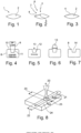
- the Figure 1 shows a lens blank 2 as transmitive optics 1.
- the Figure 2 shows how this blank 2 is processed using an ablation laser 3. This was done in the in Figure 2
- the indicated material removal 4 is already achieved with the laser 3 on the left side of the lens 2.
- the shape 6 of the lens 2 is measured in the area of the machined surface using the measuring device 5. This makes it possible to influence the type of pulse of the laser 3 based on the measured values, preferably during processing.
- the process temperature is monitored with the pyrometer 7 during processing. The process temperature can also be influenced and possibly even regulated by influencing the type of laser beam of the laser 3.
- blank 2 After removal, blank 2 has the in Figure 3 shown shape with a reduced volume, which is due to the material removal 4.
- the blank is a plastic and in the present case an acrylate 8.
- This blank can also have other materials, such as other plastics or glass.
- the surface of the blank to be reworked is made of plastic.
- the Figure 4 shows how the laser beam 9 strikes the surface 10 of the acrylate 8 and penetrates the acrylate in the shape of a shell in the area 11.
- the pulse duration of the ablation laser is around 100 femtoseconds and this causes the acrylate to evaporate in area 11. This creates a bowl-shaped area 12 of an acrylate melt and within this bowl-shaped area 12 an area 13 made of steam.
- the Figure 6 shows how the melt 12 solidifies again and the steam 13 evaporates. This leaves the in at the end of the process Figure 7 craters 14 shown in the acrylate area 8.
- a polishing laser 20 is generally used, which is scanned along the line 21 at a scanning speed (V scan ) and a tread width 22, 23 over the surface 24.
- the polishing laser 20 is moved forward at a feed speed (V feed ) in the direction of the arrow 25 perpendicular to the line 21.
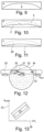
- an intraocular lens 2 from the in Figure 9 shown initial shape by means of selective material removal in Figure 10 The material surface shown is generated and then this material surface is smoothed by laser polishing until it is transparent. This creates the in Figure 11 material surface shown.
- the necessary removal depth and thus the necessary number of laser pulses at each point on the surface are determined.
- the material removal 4 can be determined by the number of laser pulses per area without changing the type of laser radiation.
- the laser beam 30 can be guided in a meandering shape over the surface to be processed, particularly for laser material removal. Based on the calculated number of laser pulses per area, the laser is switched on and off as it passes over the area to be processed.
- a beam diameter 31 of the laser radiation on the material surface is approximately 20 ⁇ m, a repetition rate of 100 kHz and a scanning speed of 32 of 1000 mm/s is used. This creates a feed speed 33 (V feed ) with which the laser 30 is guided over the lens 34.
- a laser with a wavelength of 10.6 ⁇ m is used, as this wavelength is also absorbed in the material close to the surface.
- the laser is operated continuously and the laser power is in the range of 50 to 100 watts. This means that during laser polishing the material surface is melted by the action of laser radiation and is then smoothed by the surface tension before it solidifies again.
- the processing strategy shown for the iteration is characterized by the fact that a bidirectional scanning strategy with a scanning speed of 5000 mm/s is used, thereby generating a quasi-line focus.
- This quasi-line focus 35 is guided over the surface of the lens 34 to be polished at the feed speed 33 of 30 to 40 mm/s.
- the beam diameter 31 on the workpiece is 6 mm in this exemplary embodiment.
- Temperature control is also preferably used to further improve the stability of the laser polishing.
- the Figure 14 shows a special blank 40 made by injection molding.
- This blank has a density gradient as a result of the injection molding process.
- the middle region 41 is designed with a higher density than the edge region 42.
- This density gradient can be generated in injection molding by the pressure conditions during the injection process or by multi-component injection molding in which different plastics are used.
- This density gradient leads to a special refraction of the light on the lens 40. So that the different density of the blank 40 does not affect the process of material removal and polishing, an area with a different density can also be provided inside the lens 40, while the area to be processed Surface with the surface area relevant for processing has a uniform density.
- the Figure 16 shows the intensity of different temporally successive pulses 50 to 55, which have a different intensity 56 but the same pulse duration 57 (numbered only as an example).
- the intensity 56 of the pulses 50 to 55 thus fluctuates over time 58.
- the pulse duration 57 of the individual pulses 50 to 55 can also vary accordingly, while the pulse intensity remains constant.
- the intensity 56 and the pulse duration 57 can also be varied over time and preferably regulated in order to have an optimal effect on the removal or polishing process and to achieve rapid processing without overheating.
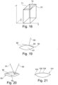
- the local intensity distribution of a pulse 60 on the spatial axes 61 and 63 is shown as an example in Figure 17 shown.
- This pulse shows a locally higher pulse energy 62 on the left side than on the right side.
- the pulse can, for example, fall slowly along the surface 64 or fall sharply along the curved surface 65, so that the right side of the pulse has a significantly lower energy concentration than its left side. This makes it possible, for example with a laser beam moving over a surface, to vary the radiation intensity applied to a surface area over time.
- the Figure 18 shows a special local energy distribution of a pulse 70, in which there is a higher energy in the edge region 71 of the pulse 70 than in the central middle region 72. This leads to a higher energy when the pulse hits the surface of a lens in the edge region of the resulting crater Energy is applied than in the central area of the crater.
- the crater therefore has less of a bowl shape and more of a rectangular shape, so that several craters placed next to each other form an approximately flat surface.
- the pulse energy distribution be varied transversely to the radiation direction during processing.
- the laser beam 82 is held essentially perpendicular to a tangent 83 at the intersection 84 of the laser beam 82 and the lens 81.
- This can be achieved by varying the orientation of the laser beam during processing and keeping the position of the lens 81 constant, or by changing the orientation of the lens 81 relative to the laser beam 82 by moving the lens 81 during processing .
- the lens and laser can also be moved in order to achieve the most perpendicular alignment of the laser beam 82 to the normal 83 on the surface of the lens.
- the laser beam can also be aligned with a mirror so that it hits the lens surface as vertically as possible.
- the density of the lens can be varied by the choice of material or material processing of the blank. However, the density can also be changed during processing by material removal and/or polishing. This makes it possible to provide different densities locally limited by the type of laser beam and as a gradient on the lens surface. The density on the material surface can be increased in such a way that reflections are prevented by the changed refractive index.
- the density can also be changed with the laser beam or by means of several laser beams 91, 92 in the interior 90 of a lens 93 so that the light refraction of the finished lens changes not as a result of the surface shape of the lens, but also as a result of a density gradient in the surface area 94 of the Lens 93 and/or in the inner region 90 of the lens 93 results.
- the arrangement of the removal craters 100 on the surface 101 of a lens 102 is shown in Figure 21 shown.
- the removal craters 100 are spaced further apart in the edge area 103 than in the central area 104. This is just an example to show how the type of processing of the surface can be varied by the number of craters per area.
- Lens 110 shown has a central middle region 111 which has a greater density than the radially outer region 112.
- the Figure 25 shows a lens 130 with a radial density gradient.
- the area of the optical axis 133 there is an area 132 with a lower density than in the area 131, which is located further radially outward. Therefore, the top view in Figure 26 a darker radially outer region 131 and a lighter central region 132 with lower density.
- the Figure 27 shows a lens 140 with a multivocal density gradient.
- areas 143 and 144 with lower optical density alternate in the radial direction from a central middle area 141 on the optical axis 142, between which there is an area 145 with higher optical density.
- the Figure 28 shows in plan view that the areas of higher and lower optical density are ring-shaped.
- the optical density can change as a gradient into a changed optical density and, alternatively, areas of different optical densities can be clearly defined next to one another.
- the varying optical density can be used to influence the refractive behavior of the lens when a light beam passes through and its deflection.
- the reflection properties, in particular at the interface of the lens surface can also be influenced via its density and the hardness that usually accompanies it.
Landscapes
- Engineering & Computer Science (AREA)
- Physics & Mathematics (AREA)
- Optics & Photonics (AREA)
- Mechanical Engineering (AREA)
- Health & Medical Sciences (AREA)
- Manufacturing & Machinery (AREA)
- Ophthalmology & Optometry (AREA)
- Plasma & Fusion (AREA)
- Chemical & Material Sciences (AREA)
- Materials Engineering (AREA)
- General Physics & Mathematics (AREA)
- General Health & Medical Sciences (AREA)
- Cardiology (AREA)
- Oral & Maxillofacial Surgery (AREA)
- Transplantation (AREA)
- Biomedical Technology (AREA)
- Heart & Thoracic Surgery (AREA)
- Vascular Medicine (AREA)
- Life Sciences & Earth Sciences (AREA)
- Animal Behavior & Ethology (AREA)
- Public Health (AREA)
- Veterinary Medicine (AREA)
- Laser Beam Processing (AREA)
- Eyeglasses (AREA)
- Optical Communication System (AREA)
- Crystals, And After-Treatments Of Crystals (AREA)
Applications Claiming Priority (3)
| Application Number | Priority Date | Filing Date | Title |
|---|---|---|---|
| DE102016014747 | 2016-12-13 | ||
| DE102017002986.5A DE102017002986B4 (de) | 2016-12-13 | 2017-03-28 | Verfahren zur Herstellung einer transmitiven Optik und Intraokularlinse |
| PCT/DE2017/000337 WO2018108192A1 (de) | 2016-12-13 | 2017-10-12 | Verfahren zur herstellung einer transmitiven optik |
Publications (3)
| Publication Number | Publication Date |
|---|---|
| EP3554756A1 EP3554756A1 (de) | 2019-10-23 |
| EP3554756B1 true EP3554756B1 (de) | 2023-09-27 |
| EP3554756C0 EP3554756C0 (de) | 2023-09-27 |
Family
ID=62201812
Family Applications (1)
| Application Number | Title | Priority Date | Filing Date |
|---|---|---|---|
| EP17801008.8A Active EP3554756B1 (de) | 2016-12-13 | 2017-10-12 | Verfahren zur herstellung einer transmitiven optik |
Country Status (16)
| Country | Link |
|---|---|
| US (1) | US11786994B2 (pl) |
| EP (1) | EP3554756B1 (pl) |
| JP (1) | JP7235656B2 (pl) |
| KR (1) | KR102446155B1 (pl) |
| CN (1) | CN110461531B (pl) |
| AU (1) | AU2017376731B2 (pl) |
| BR (1) | BR112019011695B1 (pl) |
| CA (1) | CA3047008A1 (pl) |
| DE (1) | DE102017002986B4 (pl) |
| ES (1) | ES2966971T3 (pl) |
| IL (1) | IL267091B2 (pl) |
| MX (1) | MX2019006839A (pl) |
| PL (1) | PL3554756T3 (pl) |
| RU (1) | RU2746925C2 (pl) |
| SG (1) | SG10202105869VA (pl) |
| WO (1) | WO2018108192A1 (pl) |
Cited By (1)
| Publication number | Priority date | Publication date | Assignee | Title |
|---|---|---|---|---|
| WO2025214996A1 (de) * | 2024-04-11 | 2025-10-16 | Fraunhofer-Gesellschaft zur Förderung der angewandten Forschung e. V. | Verfahren und vorrichtung zur formkorrektur eines optischen bauelements mittels laserstrahlung |
Families Citing this family (12)
| Publication number | Priority date | Publication date | Assignee | Title |
|---|---|---|---|---|
| WO2018160169A1 (en) * | 2017-02-28 | 2018-09-07 | Hewlett-Packard Development Company, L.P. | Radiation amount determination for an intended surface property level |
| DE102019207421B4 (de) * | 2019-05-21 | 2023-05-17 | Fraunhofer-Gesellschaft zur Förderung der angewandten Forschung e.V. | Verfahren zum Glätten einer Oberfläche eines Bauteils durch Bearbeitung mit energetischer Strahlung |
| DE102019211001A1 (de) | 2019-07-24 | 2021-01-28 | Fraunhofer-Gesellschaft zur Förderung der angewandten Forschung e.V. | Verfahren zur digitalen Erzeugung eines optischen Elements mit integrierten Funktionalitäten und derart hergestelltes optisches Element |
| CN111123567B (zh) * | 2020-01-16 | 2020-09-15 | 深圳市乐华数码科技有限公司 | 一种显示器屏幕曲面镀膜工艺及应用该工艺制成的显示器 |
| EP3964355A1 (en) * | 2020-09-03 | 2022-03-09 | Boegli-Gravures S.A. | A method and system for manufacturing an embossing device |
| DE102020214038A1 (de) | 2020-11-09 | 2022-05-12 | Zf Friedrichshafen Ag | Verfahren zur Behandlung eines lichtdurchlässigen Frontelements eines optischen Sensors für ein Fahrzeug |
| EP3995283B1 (en) * | 2020-11-10 | 2023-10-11 | Gerresheimer Regensburg GmbH | Laser cutting of microinjection moulded parts |
| KR102452559B1 (ko) * | 2021-04-23 | 2022-10-14 | 주식회사 이엠엘 | 3d 프린팅을 이용한 다이아몬드 적층 방법 |
| DE102021204662A1 (de) | 2021-05-07 | 2022-11-10 | Carl Zeiss Meditec Ag | Künstliche Augenlinse und Verfahren zu deren Herstellung |
| DE102022000647A1 (de) | 2021-11-25 | 2023-05-25 | AIXLens GmbH | Kunststoff sowie Verfahren zum Bearbeiten eines Kuststoffs |
| IL312925A (en) | 2021-11-25 | 2024-07-01 | AIXLens GmbH | Plastic material, and method for processing a plastic material |
| DE102023106479A1 (de) * | 2023-03-15 | 2024-09-19 | Fraunhofer-Gesellschaft zur Förderung der angewandten Forschung eingetragener Verein | Verfahren zum Polieren von Werkstücken durch Bearbeitung mit energetischer Strahlung |
Family Cites Families (36)
| Publication number | Priority date | Publication date | Assignee | Title |
|---|---|---|---|---|
| EP0367513B1 (en) * | 1988-11-02 | 1995-07-05 | Btg International Limited | Contact lens cast moulding |
| SU1760486A1 (ru) * | 1990-08-22 | 1992-09-07 | Научно-исследовательский центр по технологическим лазерам АН СССР | Способ изготовлени оптических элементов из щелочно-галоидных материалов |
| USRE36872E (en) * | 1992-01-15 | 2000-09-12 | Laser Industries Ltd. | System for causing ablation of irradiated material of living tissue while not causing damage below a predetermined depth |
| DE29505985U1 (de) | 1995-04-06 | 1995-07-20 | Bestenlehrer, Alexander, 91074 Herzogenaurach | Vorrichtung zum Bearbeiten, insbesondere zum Polieren und Strukturieren von beliebigen 3D-Formflächen mittels eines Laserstrahls |
| US6215096B1 (en) | 1997-01-21 | 2001-04-10 | TECHNOMED GESELLSCHAFT FüR MED. UND MED.-TECHN. SYSTEME MBH | Method for determining a required shape for at least one surface of an artificial or natural part of an eye which is intersected by a path of rays through the pupil of the eye, and device for the manufacture of an artificial lens |
| CA2380541A1 (en) * | 1999-07-29 | 2001-02-08 | Corning Incorporated | Direct writing of optical devices in silica-based glass using femtosecond pulse lasers |
| DE10006896A1 (de) * | 2000-02-16 | 2001-08-30 | Wavelight Laser Technologie Ag | Verfahren zum Herstellen einer künstlichen okularen Linse |
| JP2002131503A (ja) * | 2000-10-19 | 2002-05-09 | Seiko Epson Corp | 光学レンズの平滑処理方法およびこれを用いた光学レンズの製造方法、光学レンズの平滑処理装置 |
| US7014317B2 (en) * | 2001-11-02 | 2006-03-21 | Essilor International (Compagnie Generale D'optique) | Method for manufacturing multifocal lenses |
| DE10202036A1 (de) * | 2002-01-18 | 2003-07-31 | Zeiss Carl Meditec Ag | Femtosekunden Lasersystem zur präzisen Bearbeitung von Material und Gewebe |
| DE10228743B4 (de) * | 2002-06-27 | 2005-05-04 | Fraunhofer-Gesellschaft zur Förderung der angewandten Forschung e.V. | Verfahren zum Glätten und Polieren von Oberflächen durch Bearbeitung mit Laserstrahlung |
| US20050155956A1 (en) * | 2002-08-30 | 2005-07-21 | Sumitomo Heavy Industries, Ltd. | Laser processing method and processing device |
| DE10241211B4 (de) | 2002-09-05 | 2004-09-16 | Technovision GmbH Gesellschaft für die Entwicklung medizinischer Technologie | Vorrichtung und Verfahren zum Herstellen kundenspezifischer weicher Kontaktlinsen |
| DE10316576B3 (de) * | 2003-04-10 | 2004-11-18 | Technovision GmbH Gesellschaft für die Entwicklung medizinischer Technologie | Verfahren und Vorrichtung zum Herstellen weicher Kontaktlinsen |
| US7351241B2 (en) * | 2003-06-02 | 2008-04-01 | Carl Zeiss Meditec Ag | Method and apparatus for precision working of material |
| US20060192310A1 (en) * | 2005-02-23 | 2006-08-31 | Lindacher Joseph M | Method of manufacturing ophthalmic lenses using modulated energy |
| US7642205B2 (en) * | 2005-04-08 | 2010-01-05 | Mattson Technology, Inc. | Rapid thermal processing using energy transfer layers |
| US7169017B1 (en) * | 2005-08-10 | 2007-01-30 | Rohm And Haas Electronic Materials Cmp Holdings, Inc. | Polishing pad having a window with reduced surface roughness |
| FI20060177A7 (fi) * | 2006-02-23 | 2007-08-24 | Picodeon Ltd Oy | Menetelmä tuottaa hyvälaatuisia pintoja ja hyvälaatuisen pinnan omaava tuote |
| DE102006051550B4 (de) * | 2006-10-30 | 2012-02-02 | Fhr Anlagenbau Gmbh | Verfahren und Vorrichtung zum Strukturieren von Bauteilen unter Verwendung eines Werkstoffs auf der Basis von Siliziumoxid |
| EP1973110A3 (en) * | 2007-03-19 | 2009-04-29 | Ricoh Company, Ltd. | Minute structure and information recording medium |
| DE102007058105A1 (de) * | 2007-12-03 | 2009-06-10 | Carl Zeiss Smt Ag | Vorrichtung und Verfahren zur Bearbeitung von optischen Elementen mittels Laserablation |
| US7901075B2 (en) * | 2007-12-27 | 2011-03-08 | Johnson & Johnson Vision Care, Inc. | Laser enhanced lens |
| CN102088929A (zh) * | 2008-07-15 | 2011-06-08 | 美你康株式会社 | 眼内透镜及其制造方法 |
| DE102008038395B3 (de) * | 2008-08-19 | 2009-11-05 | Surcoatec International Ag | Verfahren zum Glätten der Oberfläche eines Substrates unter Verwendung eines Lasers |
| DE102011103793A1 (de) | 2011-03-10 | 2012-09-27 | Fraunhofer-Gesellschaft zur Förderung der angewandten Forschung e.V. | Verfahren zur Fertigung optischer Elemente durch Bearbeitung mit energetischer Strahlung |
| US8974055B2 (en) * | 2013-03-15 | 2015-03-10 | Johnson & Johnson Vision Care, Inc. | Method and apparatus for encapsulating a rigid insert in a contact lens for correcting vision in astigmatic patients |
| CN105453232B (zh) * | 2013-08-10 | 2019-04-05 | 应用材料公司 | 具有促进受控的调节的材料组成的cmp垫 |
| US20150167926A1 (en) | 2013-12-16 | 2015-06-18 | Vode Lighting Llc | Lighting optics for luminaires |
| JP6255255B2 (ja) * | 2014-01-27 | 2017-12-27 | 株式会社ディスコ | 光デバイスの加工方法 |
| DE102014012046A1 (de) * | 2014-04-29 | 2015-10-29 | Uwe Clasen | Verfahren zur Herstellung einer optischen Linse und eine nach diesem Verfahren hergestellte Linse |
| WO2015165435A1 (de) * | 2014-04-29 | 2015-11-05 | Clasen Uwe M | Verfahren zur herstellung einer optischen linse und eine nach diesem verfahren hergestellte linse |
| US9895772B2 (en) * | 2014-10-03 | 2018-02-20 | Gentex Corporation | Second surface laser ablation |
| JP6755248B2 (ja) * | 2014-11-27 | 2020-09-16 | サフィーロ・ソシエタ・アツィオナリア・ファブリカ・イタリアナ・ラボラツィオーネ・オッチアリ・エス・ピー・エー | 眼鏡用レンズを製造する方法、その方法で作製されたレンズ、およびそのレンズを備えた眼鏡 |
| RU2591034C1 (ru) * | 2015-04-07 | 2016-07-10 | Акционерное общество "Швабе - Приборы" | Способ изготовления многофункциональных прецизионных оптических прицельных сеток методом лазерной абляции с запуском |
| US10688597B2 (en) * | 2016-12-15 | 2020-06-23 | Tectus Corporation | Polishing optical elements with a femtosecond laser beam |
-
2017
- 2017-03-28 DE DE102017002986.5A patent/DE102017002986B4/de active Active
- 2017-10-12 MX MX2019006839A patent/MX2019006839A/es unknown
- 2017-10-12 CA CA3047008A patent/CA3047008A1/en active Pending
- 2017-10-12 JP JP2019531259A patent/JP7235656B2/ja active Active
- 2017-10-12 CN CN201780086396.8A patent/CN110461531B/zh active Active
- 2017-10-12 WO PCT/DE2017/000337 patent/WO2018108192A1/de not_active Ceased
- 2017-10-12 KR KR1020197019364A patent/KR102446155B1/ko active Active
- 2017-10-12 AU AU2017376731A patent/AU2017376731B2/en active Active
- 2017-10-12 RU RU2019121901A patent/RU2746925C2/ru active
- 2017-10-12 ES ES17801008T patent/ES2966971T3/es active Active
- 2017-10-12 EP EP17801008.8A patent/EP3554756B1/de active Active
- 2017-10-12 BR BR112019011695-8A patent/BR112019011695B1/pt active IP Right Grant
- 2017-10-12 US US16/468,397 patent/US11786994B2/en active Active
- 2017-10-12 IL IL267091A patent/IL267091B2/en unknown
- 2017-10-12 SG SG10202105869VA patent/SG10202105869VA/en unknown
- 2017-10-12 PL PL17801008.8T patent/PL3554756T3/pl unknown
Cited By (1)
| Publication number | Priority date | Publication date | Assignee | Title |
|---|---|---|---|---|
| WO2025214996A1 (de) * | 2024-04-11 | 2025-10-16 | Fraunhofer-Gesellschaft zur Förderung der angewandten Forschung e. V. | Verfahren und vorrichtung zur formkorrektur eines optischen bauelements mittels laserstrahlung |
Also Published As
| Publication number | Publication date |
|---|---|
| DE102017002986B4 (de) | 2019-08-29 |
| BR112019011695B1 (pt) | 2022-09-06 |
| RU2746925C2 (ru) | 2021-04-22 |
| AU2017376731B2 (en) | 2023-07-20 |
| BR112019011695A2 (pt) | 2019-10-22 |
| IL267091B1 (en) | 2024-05-01 |
| KR102446155B1 (ko) | 2022-09-22 |
| SG10202105869VA (en) | 2021-07-29 |
| KR20190094392A (ko) | 2019-08-13 |
| AU2017376731A1 (en) | 2019-06-27 |
| DE102017002986A1 (de) | 2018-06-14 |
| US20210260842A1 (en) | 2021-08-26 |
| RU2019121901A3 (pl) | 2021-01-15 |
| CA3047008A1 (en) | 2018-06-21 |
| CN110461531A (zh) | 2019-11-15 |
| IL267091A (en) | 2019-08-29 |
| PL3554756T3 (pl) | 2024-03-18 |
| RU2019121901A (ru) | 2021-01-15 |
| EP3554756A1 (de) | 2019-10-23 |
| ES2966971T3 (es) | 2024-04-25 |
| JP7235656B2 (ja) | 2023-03-08 |
| WO2018108192A1 (de) | 2018-06-21 |
| EP3554756C0 (de) | 2023-09-27 |
| IL267091B2 (en) | 2024-09-01 |
| MX2019006839A (es) | 2019-08-26 |
| CN110461531B (zh) | 2022-04-12 |
| US11786994B2 (en) | 2023-10-17 |
| JP2020503542A (ja) | 2020-01-30 |
Similar Documents
| Publication | Publication Date | Title |
|---|---|---|
| EP3554756B1 (de) | Verfahren zur herstellung einer transmitiven optik | |
| EP3554757B1 (de) | Verfahren zur herstellung einer transmitiven oder reflektiven optik | |
| EP1470623B1 (de) | Femtosekunden-lasersystem zur präzisen bearbeitung von material und gewebe | |
| DE102009012873B4 (de) | Ophthalmologisches Lasersystem und Steuereinheit | |
| EP1034062B1 (de) | Vorrichtung zur formgebung von objekten | |
| EP1628606B1 (de) | Vorrichtung zum präzisen bearbeiten von material | |
| EP3363416A1 (de) | Vorrichtung und verfahren zum erzeugen von steuerdaten zur operativen fehlsichtigkeitskorrektur eines auges | |
| EP2760622A2 (de) | Vorrichtung zum laserschneiden innerhalb transparenter materialien | |
| EP2593057B1 (de) | Steuerdatenerzeugung für die augenchirurgische fehlsichtigkeitsbehandlung | |
| HK40014623A (en) | Method for producing a transmissive optics | |
| HK40014623B (en) | Method for producing a transmissive optics | |
| DE102023201418A1 (de) | Verfahren zur Herstellung eines Funktionselements mit Oberflächenstrukturen sowie Funktionselement |
Legal Events
| Date | Code | Title | Description |
|---|---|---|---|
| STAA | Information on the status of an ep patent application or granted ep patent |
Free format text: STATUS: UNKNOWN |
|
| STAA | Information on the status of an ep patent application or granted ep patent |
Free format text: STATUS: THE INTERNATIONAL PUBLICATION HAS BEEN MADE |
|
| PUAI | Public reference made under article 153(3) epc to a published international application that has entered the european phase |
Free format text: ORIGINAL CODE: 0009012 |
|
| STAA | Information on the status of an ep patent application or granted ep patent |
Free format text: STATUS: REQUEST FOR EXAMINATION WAS MADE |
|
| 17P | Request for examination filed |
Effective date: 20190614 |
|
| AK | Designated contracting states |
Kind code of ref document: A1 Designated state(s): AL AT BE BG CH CY CZ DE DK EE ES FI FR GB GR HR HU IE IS IT LI LT LU LV MC MK MT NL NO PL PT RO RS SE SI SK SM TR |
|
| AX | Request for extension of the european patent |
Extension state: BA ME |
|
| RIN1 | Information on inventor provided before grant (corrected) |
Inventor name: VON WALLFELD, AXEL Inventor name: CLASEN, UWE Inventor name: WILLENBORG, EDGAR Inventor name: WEINGARTEN, CHRISTIAN Inventor name: POPRAWE, REINHART Inventor name: FORNAROLI, CHRISTIAN |
|
| DAV | Request for validation of the european patent (deleted) | ||
| DAX | Request for extension of the european patent (deleted) | ||
| STAA | Information on the status of an ep patent application or granted ep patent |
Free format text: STATUS: EXAMINATION IS IN PROGRESS |
|
| 17Q | First examination report despatched |
Effective date: 20220728 |
|
| GRAP | Despatch of communication of intention to grant a patent |
Free format text: ORIGINAL CODE: EPIDOSNIGR1 |
|
| STAA | Information on the status of an ep patent application or granted ep patent |
Free format text: STATUS: GRANT OF PATENT IS INTENDED |
|
| INTG | Intention to grant announced |
Effective date: 20230706 |
|
| GRAS | Grant fee paid |
Free format text: ORIGINAL CODE: EPIDOSNIGR3 |
|
| GRAA | (expected) grant |
Free format text: ORIGINAL CODE: 0009210 |
|
| STAA | Information on the status of an ep patent application or granted ep patent |
Free format text: STATUS: THE PATENT HAS BEEN GRANTED |
|
| AK | Designated contracting states |
Kind code of ref document: B1 Designated state(s): AL AT BE BG CH CY CZ DE DK EE ES FI FR GB GR HR HU IE IS IT LI LT LU LV MC MK MT NL NO PL PT RO RS SE SI SK SM TR |
|
| REG | Reference to a national code |
Ref country code: GB Ref legal event code: FG4D Free format text: NOT ENGLISH |
|
| REG | Reference to a national code |
Ref country code: CH Ref legal event code: EP |
|
| REG | Reference to a national code |
Ref country code: DE Ref legal event code: R096 Ref document number: 502017015430 Country of ref document: DE |
|
| REG | Reference to a national code |
Ref country code: IE Ref legal event code: FG4D Free format text: LANGUAGE OF EP DOCUMENT: GERMAN |
|
| U01 | Request for unitary effect filed |
Effective date: 20231020 |
|
| U07 | Unitary effect registered |
Designated state(s): AT BE BG DE DK EE FI FR IT LT LU LV MT NL PT SE SI Effective date: 20231027 |
|
| U20 | Renewal fee for the european patent with unitary effect paid |
Year of fee payment: 7 Effective date: 20231027 |
|
| REG | Reference to a national code |
Ref country code: NO Ref legal event code: T2 Effective date: 20230927 |
|
| PG25 | Lapsed in a contracting state [announced via postgrant information from national office to epo] |
Ref country code: GR Free format text: LAPSE BECAUSE OF FAILURE TO SUBMIT A TRANSLATION OF THE DESCRIPTION OR TO PAY THE FEE WITHIN THE PRESCRIBED TIME-LIMIT Effective date: 20231228 |
|
| PG25 | Lapsed in a contracting state [announced via postgrant information from national office to epo] |
Ref country code: RS Free format text: LAPSE BECAUSE OF FAILURE TO SUBMIT A TRANSLATION OF THE DESCRIPTION OR TO PAY THE FEE WITHIN THE PRESCRIBED TIME-LIMIT Effective date: 20230927 Ref country code: HR Free format text: LAPSE BECAUSE OF FAILURE TO SUBMIT A TRANSLATION OF THE DESCRIPTION OR TO PAY THE FEE WITHIN THE PRESCRIBED TIME-LIMIT Effective date: 20230927 Ref country code: GR Free format text: LAPSE BECAUSE OF FAILURE TO SUBMIT A TRANSLATION OF THE DESCRIPTION OR TO PAY THE FEE WITHIN THE PRESCRIBED TIME-LIMIT Effective date: 20231228 |
|
| PG25 | Lapsed in a contracting state [announced via postgrant information from national office to epo] |
Ref country code: IS Free format text: LAPSE BECAUSE OF FAILURE TO SUBMIT A TRANSLATION OF THE DESCRIPTION OR TO PAY THE FEE WITHIN THE PRESCRIBED TIME-LIMIT Effective date: 20240127 |
|
| REG | Reference to a national code |
Ref country code: ES Ref legal event code: FG2A Ref document number: 2966971 Country of ref document: ES Kind code of ref document: T3 Effective date: 20240425 |
|
| PG25 | Lapsed in a contracting state [announced via postgrant information from national office to epo] |
Ref country code: SM Free format text: LAPSE BECAUSE OF FAILURE TO SUBMIT A TRANSLATION OF THE DESCRIPTION OR TO PAY THE FEE WITHIN THE PRESCRIBED TIME-LIMIT Effective date: 20230927 Ref country code: RO Free format text: LAPSE BECAUSE OF FAILURE TO SUBMIT A TRANSLATION OF THE DESCRIPTION OR TO PAY THE FEE WITHIN THE PRESCRIBED TIME-LIMIT Effective date: 20230927 Ref country code: IS Free format text: LAPSE BECAUSE OF FAILURE TO SUBMIT A TRANSLATION OF THE DESCRIPTION OR TO PAY THE FEE WITHIN THE PRESCRIBED TIME-LIMIT Effective date: 20240127 Ref country code: SK Free format text: LAPSE BECAUSE OF FAILURE TO SUBMIT A TRANSLATION OF THE DESCRIPTION OR TO PAY THE FEE WITHIN THE PRESCRIBED TIME-LIMIT Effective date: 20230927 |
|
| REG | Reference to a national code |
Ref country code: DE Ref legal event code: R097 Ref document number: 502017015430 Country of ref document: DE |
|
| PG25 | Lapsed in a contracting state [announced via postgrant information from national office to epo] |
Ref country code: MC Free format text: LAPSE BECAUSE OF FAILURE TO SUBMIT A TRANSLATION OF THE DESCRIPTION OR TO PAY THE FEE WITHIN THE PRESCRIBED TIME-LIMIT Effective date: 20230927 |
|
| PG25 | Lapsed in a contracting state [announced via postgrant information from national office to epo] |
Ref country code: MC Free format text: LAPSE BECAUSE OF FAILURE TO SUBMIT A TRANSLATION OF THE DESCRIPTION OR TO PAY THE FEE WITHIN THE PRESCRIBED TIME-LIMIT Effective date: 20230927 |
|
| PLBE | No opposition filed within time limit |
Free format text: ORIGINAL CODE: 0009261 |
|
| STAA | Information on the status of an ep patent application or granted ep patent |
Free format text: STATUS: NO OPPOSITION FILED WITHIN TIME LIMIT |
|
| 26N | No opposition filed |
Effective date: 20240628 |
|
| PG25 | Lapsed in a contracting state [announced via postgrant information from national office to epo] |
Ref country code: IE Free format text: LAPSE BECAUSE OF NON-PAYMENT OF DUE FEES Effective date: 20231012 |
|
| U20 | Renewal fee for the european patent with unitary effect paid |
Year of fee payment: 8 Effective date: 20240917 |
|
| PG25 | Lapsed in a contracting state [announced via postgrant information from national office to epo] |
Ref country code: IE Free format text: LAPSE BECAUSE OF NON-PAYMENT OF DUE FEES Effective date: 20231012 |
|
| PG25 | Lapsed in a contracting state [announced via postgrant information from national office to epo] |
Ref country code: CY Free format text: LAPSE BECAUSE OF FAILURE TO SUBMIT A TRANSLATION OF THE DESCRIPTION OR TO PAY THE FEE WITHIN THE PRESCRIBED TIME-LIMIT; INVALID AB INITIO Effective date: 20171012 |
|
| PG25 | Lapsed in a contracting state [announced via postgrant information from national office to epo] |
Ref country code: HU Free format text: LAPSE BECAUSE OF FAILURE TO SUBMIT A TRANSLATION OF THE DESCRIPTION OR TO PAY THE FEE WITHIN THE PRESCRIBED TIME-LIMIT; INVALID AB INITIO Effective date: 20171012 |
|
| PGFP | Annual fee paid to national office [announced via postgrant information from national office to epo] |
Ref country code: PL Payment date: 20250918 Year of fee payment: 9 |
|
| REG | Reference to a national code |
Ref country code: CH Ref legal event code: U11 Free format text: ST27 STATUS EVENT CODE: U-0-0-U10-U11 (AS PROVIDED BY THE NATIONAL OFFICE) Effective date: 20251101 |
|
| U20 | Renewal fee for the european patent with unitary effect paid |
Year of fee payment: 9 Effective date: 20251017 |
|
| PGFP | Annual fee paid to national office [announced via postgrant information from national office to epo] |
Ref country code: GB Payment date: 20251022 Year of fee payment: 9 |
|
| PGFP | Annual fee paid to national office [announced via postgrant information from national office to epo] |
Ref country code: NO Payment date: 20251024 Year of fee payment: 9 |
|
| PGFP | Annual fee paid to national office [announced via postgrant information from national office to epo] |
Ref country code: TR Payment date: 20251006 Year of fee payment: 9 |
|
| PGFP | Annual fee paid to national office [announced via postgrant information from national office to epo] |
Ref country code: CH Payment date: 20251101 Year of fee payment: 9 |
|
| PGFP | Annual fee paid to national office [announced via postgrant information from national office to epo] |
Ref country code: CZ Payment date: 20251009 Year of fee payment: 9 |
|
| PGFP | Annual fee paid to national office [announced via postgrant information from national office to epo] |
Ref country code: ES Payment date: 20251216 Year of fee payment: 9 |