EP3554612B1 - Cathéters à ballonnet - Google Patents
Cathéters à ballonnet Download PDFInfo
- Publication number
- EP3554612B1 EP3554612B1 EP17879736.1A EP17879736A EP3554612B1 EP 3554612 B1 EP3554612 B1 EP 3554612B1 EP 17879736 A EP17879736 A EP 17879736A EP 3554612 B1 EP3554612 B1 EP 3554612B1
- Authority
- EP
- European Patent Office
- Prior art keywords
- elongate body
- scoring
- balloon
- catheter
- coupler
- Prior art date
- Legal status (The legal status is an assumption and is not a legal conclusion. Google has not performed a legal analysis and makes no representation as to the accuracy of the status listed.)
- Active
Links
Images


Classifications
-
- A—HUMAN NECESSITIES
- A61—MEDICAL OR VETERINARY SCIENCE; HYGIENE
- A61B—DIAGNOSIS; SURGERY; IDENTIFICATION
- A61B17/00—Surgical instruments, devices or methods
- A61B17/32—Surgical cutting instruments
- A61B17/3205—Excision instruments
- A61B17/3207—Atherectomy devices working by cutting or abrading; Similar devices specially adapted for non-vascular obstructions
- A61B17/320725—Atherectomy devices working by cutting or abrading; Similar devices specially adapted for non-vascular obstructions with radially expandable cutting or abrading elements
-
- A—HUMAN NECESSITIES
- A61—MEDICAL OR VETERINARY SCIENCE; HYGIENE
- A61M—DEVICES FOR INTRODUCING MEDIA INTO, OR ONTO, THE BODY; DEVICES FOR TRANSDUCING BODY MEDIA OR FOR TAKING MEDIA FROM THE BODY; DEVICES FOR PRODUCING OR ENDING SLEEP OR STUPOR
- A61M25/00—Catheters; Hollow probes
- A61M25/0043—Catheters; Hollow probes characterised by structural features
- A61M25/005—Catheters; Hollow probes characterised by structural features with embedded materials for reinforcement, e.g. wires, coils, braids
- A61M25/0052—Localized reinforcement, e.g. where only a specific part of the catheter is reinforced, for rapid exchange guidewire port
-
- A—HUMAN NECESSITIES
- A61—MEDICAL OR VETERINARY SCIENCE; HYGIENE
- A61M—DEVICES FOR INTRODUCING MEDIA INTO, OR ONTO, THE BODY; DEVICES FOR TRANSDUCING BODY MEDIA OR FOR TAKING MEDIA FROM THE BODY; DEVICES FOR PRODUCING OR ENDING SLEEP OR STUPOR
- A61M25/00—Catheters; Hollow probes
- A61M25/0043—Catheters; Hollow probes characterised by structural features
- A61M25/0054—Catheters; Hollow probes characterised by structural features with regions for increasing flexibility
-
- A—HUMAN NECESSITIES
- A61—MEDICAL OR VETERINARY SCIENCE; HYGIENE
- A61M—DEVICES FOR INTRODUCING MEDIA INTO, OR ONTO, THE BODY; DEVICES FOR TRANSDUCING BODY MEDIA OR FOR TAKING MEDIA FROM THE BODY; DEVICES FOR PRODUCING OR ENDING SLEEP OR STUPOR
- A61M25/00—Catheters; Hollow probes
- A61M25/01—Introducing, guiding, advancing, emplacing or holding catheters
- A61M25/0105—Steering means as part of the catheter or advancing means; Markers for positioning
- A61M25/0108—Steering means as part of the catheter or advancing means; Markers for positioning using radio-opaque or ultrasound markers
-
- A—HUMAN NECESSITIES
- A61—MEDICAL OR VETERINARY SCIENCE; HYGIENE
- A61M—DEVICES FOR INTRODUCING MEDIA INTO, OR ONTO, THE BODY; DEVICES FOR TRANSDUCING BODY MEDIA OR FOR TAKING MEDIA FROM THE BODY; DEVICES FOR PRODUCING OR ENDING SLEEP OR STUPOR
- A61M25/00—Catheters; Hollow probes
- A61M25/01—Introducing, guiding, advancing, emplacing or holding catheters
- A61M25/09—Guide wires
-
- A—HUMAN NECESSITIES
- A61—MEDICAL OR VETERINARY SCIENCE; HYGIENE
- A61M—DEVICES FOR INTRODUCING MEDIA INTO, OR ONTO, THE BODY; DEVICES FOR TRANSDUCING BODY MEDIA OR FOR TAKING MEDIA FROM THE BODY; DEVICES FOR PRODUCING OR ENDING SLEEP OR STUPOR
- A61M25/00—Catheters; Hollow probes
- A61M25/10—Balloon catheters
- A61M25/1027—Making of balloon catheters
- A61M25/1034—Joining of shaft and balloon
-
- A—HUMAN NECESSITIES
- A61—MEDICAL OR VETERINARY SCIENCE; HYGIENE
- A61M—DEVICES FOR INTRODUCING MEDIA INTO, OR ONTO, THE BODY; DEVICES FOR TRANSDUCING BODY MEDIA OR FOR TAKING MEDIA FROM THE BODY; DEVICES FOR PRODUCING OR ENDING SLEEP OR STUPOR
- A61M25/00—Catheters; Hollow probes
- A61M25/10—Balloon catheters
- A61M25/104—Balloon catheters used for angioplasty
-
- A—HUMAN NECESSITIES
- A61—MEDICAL OR VETERINARY SCIENCE; HYGIENE
- A61B—DIAGNOSIS; SURGERY; IDENTIFICATION
- A61B17/00—Surgical instruments, devices or methods
- A61B2017/00477—Coupling
-
- A—HUMAN NECESSITIES
- A61—MEDICAL OR VETERINARY SCIENCE; HYGIENE
- A61B—DIAGNOSIS; SURGERY; IDENTIFICATION
- A61B17/00—Surgical instruments, devices or methods
- A61B2017/00535—Surgical instruments, devices or methods pneumatically or hydraulically operated
- A61B2017/00557—Surgical instruments, devices or methods pneumatically or hydraulically operated inflatable
-
- A—HUMAN NECESSITIES
- A61—MEDICAL OR VETERINARY SCIENCE; HYGIENE
- A61M—DEVICES FOR INTRODUCING MEDIA INTO, OR ONTO, THE BODY; DEVICES FOR TRANSDUCING BODY MEDIA OR FOR TAKING MEDIA FROM THE BODY; DEVICES FOR PRODUCING OR ENDING SLEEP OR STUPOR
- A61M25/00—Catheters; Hollow probes
- A61M25/0043—Catheters; Hollow probes characterised by structural features
- A61M2025/0059—Catheters; Hollow probes characterised by structural features having means for preventing the catheter, sheath or lumens from collapsing due to outer forces, e.g. compressing forces, or caused by twisting or kinking
-
- A—HUMAN NECESSITIES
- A61—MEDICAL OR VETERINARY SCIENCE; HYGIENE
- A61M—DEVICES FOR INTRODUCING MEDIA INTO, OR ONTO, THE BODY; DEVICES FOR TRANSDUCING BODY MEDIA OR FOR TAKING MEDIA FROM THE BODY; DEVICES FOR PRODUCING OR ENDING SLEEP OR STUPOR
- A61M25/00—Catheters; Hollow probes
- A61M25/01—Introducing, guiding, advancing, emplacing or holding catheters
- A61M2025/0183—Rapid exchange or monorail catheters
-
- A—HUMAN NECESSITIES
- A61—MEDICAL OR VETERINARY SCIENCE; HYGIENE
- A61M—DEVICES FOR INTRODUCING MEDIA INTO, OR ONTO, THE BODY; DEVICES FOR TRANSDUCING BODY MEDIA OR FOR TAKING MEDIA FROM THE BODY; DEVICES FOR PRODUCING OR ENDING SLEEP OR STUPOR
- A61M25/00—Catheters; Hollow probes
- A61M25/10—Balloon catheters
- A61M2025/1043—Balloon catheters with special features or adapted for special applications
- A61M2025/1079—Balloon catheters with special features or adapted for special applications having radio-opaque markers in the region of the balloon
-
- A—HUMAN NECESSITIES
- A61—MEDICAL OR VETERINARY SCIENCE; HYGIENE
- A61M—DEVICES FOR INTRODUCING MEDIA INTO, OR ONTO, THE BODY; DEVICES FOR TRANSDUCING BODY MEDIA OR FOR TAKING MEDIA FROM THE BODY; DEVICES FOR PRODUCING OR ENDING SLEEP OR STUPOR
- A61M25/00—Catheters; Hollow probes
- A61M25/10—Balloon catheters
- A61M2025/1043—Balloon catheters with special features or adapted for special applications
- A61M2025/1081—Balloon catheters with special features or adapted for special applications having sheaths or the like for covering the balloon but not forming a permanent part of the balloon, e.g. retractable, dissolvable or tearable sheaths
-
- A—HUMAN NECESSITIES
- A61—MEDICAL OR VETERINARY SCIENCE; HYGIENE
- A61M—DEVICES FOR INTRODUCING MEDIA INTO, OR ONTO, THE BODY; DEVICES FOR TRANSDUCING BODY MEDIA OR FOR TAKING MEDIA FROM THE BODY; DEVICES FOR PRODUCING OR ENDING SLEEP OR STUPOR
- A61M25/00—Catheters; Hollow probes
- A61M25/10—Balloon catheters
- A61M2025/1043—Balloon catheters with special features or adapted for special applications
- A61M2025/1086—Balloon catheters with special features or adapted for special applications having a special balloon surface topography, e.g. pores, protuberances, spikes or grooves
-
- A—HUMAN NECESSITIES
- A61—MEDICAL OR VETERINARY SCIENCE; HYGIENE
- A61M—DEVICES FOR INTRODUCING MEDIA INTO, OR ONTO, THE BODY; DEVICES FOR TRANSDUCING BODY MEDIA OR FOR TAKING MEDIA FROM THE BODY; DEVICES FOR PRODUCING OR ENDING SLEEP OR STUPOR
- A61M25/00—Catheters; Hollow probes
- A61M25/10—Balloon catheters
- A61M2025/1043—Balloon catheters with special features or adapted for special applications
- A61M2025/109—Balloon catheters with special features or adapted for special applications having balloons for removing solid matters, e.g. by grasping or scraping plaque, thrombus or other matters that obstruct the flow
-
- A—HUMAN NECESSITIES
- A61—MEDICAL OR VETERINARY SCIENCE; HYGIENE
- A61M—DEVICES FOR INTRODUCING MEDIA INTO, OR ONTO, THE BODY; DEVICES FOR TRANSDUCING BODY MEDIA OR FOR TAKING MEDIA FROM THE BODY; DEVICES FOR PRODUCING OR ENDING SLEEP OR STUPOR
- A61M25/00—Catheters; Hollow probes
- A61M25/10—Balloon catheters
- A61M25/1018—Balloon inflating or inflation-control devices
- A61M25/10181—Means for forcing inflation fluid into the balloon
-
- A—HUMAN NECESSITIES
- A61—MEDICAL OR VETERINARY SCIENCE; HYGIENE
- A61M—DEVICES FOR INTRODUCING MEDIA INTO, OR ONTO, THE BODY; DEVICES FOR TRANSDUCING BODY MEDIA OR FOR TAKING MEDIA FROM THE BODY; DEVICES FOR PRODUCING OR ENDING SLEEP OR STUPOR
- A61M25/00—Catheters; Hollow probes
- A61M25/10—Balloon catheters
- A61M25/1018—Balloon inflating or inflation-control devices
- A61M25/10184—Means for controlling or monitoring inflation or deflation
- A61M25/10187—Indicators for the level of inflation or deflation
Definitions
- This application generally relates to balloon catheters.
- Atherosclerosis is characterized by one or more intravascular lesions formed in part of plaque including blood-borne substances such as fat, cholesterol, and calcium.
- An intravascular lesion such as an arterial lesion can form on a wall of an arterial lumen and build out across the lumen to an opposite wall thereof. A last point of patency often occurs at a boundary between the arterial lesion and the opposite wall of the arterial lumen.
- Surgical procedures for atherosclerosis such as balloon angioplasty can be used to restore patency and blood flow lost to the one or more intravascular lesions.
- balloon catheters Because early balloons could cause wall trauma by non-uniformly unfolding during inflation, changes have been made to balloon catheters to control balloon inflation and the forces imparted thereby. However, such changes are often not isolated to the balloons of such balloon catheters. Other balloon-catheter components and the performance thereof can be affected as well. Accordingly, there is a need to control balloon inflation and the forces imparted thereby while maintaining integrity in other balloon-catheter components.
- catheters and systems that address the foregoing
- JP2009536546 discloses a balloon catheter having a shaft with a harder proximal end and a wire extending proximally along the balloon's surface surface from the catheter's tip to the harder part of the catheter where no more rigidity is needed.
- a catheter including an elongate body with a polymeric portion and a metallic portion; a balloon over at least some of the polymeric portion; a coupler formed over or between the polymeric and metallic portions; and one or more scoring wires.
- the metallic portion can include a spiral-cut portion configured to prevent elongation and kinking of the elongate body.
- the one or more scoring wires are fixed to and extend from a tip at a distal end of the elongate body, over the balloon, through the polymeric portion of the elongate body, through the coupler, and to the metallic portion of the elongate body.
- the one or more scoring wires are fixed to an internal surface of the spiral-cut portion or formed from the spiral-cut portion.
- any labels such as “left,” “right,” “front,” “back,” “top,” “bottom,” “forward,” “reverse,” “clockwise,” “counter clockwise,” “up,” “down,” or other similar terms such as “upper,” “lower,” “aft,” “fore,” “vertical,” “horizontal,” “proximal,” “distal,” and the like are used for convenience and are not intended to imply, for example, any particular fixed location, orientation, or direction. Instead, such labels are used to reflect, for example, relative location, orientation, or directions. It should also be understood that the singular forms of “a,” “an,” and “the” include plural references unless the context clearly dictates otherwise.
- Atherosclerosis is characterized by one or more intravascular lesions formed in part of plaque including blood-borne substances such as fat, cholesterol, and calcium.
- Surgical procedures for atherosclerosis such as balloon angioplasty can be used to restore patency and blood flow lost to the one or more intravascular lesions.
- balloon angioplasty can be used to restore patency and blood flow lost to the one or more intravascular lesions.
- a catheter in the present invention, includes an elongate body with a polymeric portion and a metallic portion; a balloon over at least some of the polymeric portion; a coupler formed over or between the polymeric and metallic portions; and one or more scoring wires.
- the metallic portion can include a spiral-cut portion configured to prevent elongation and kinking of the elongate body.
- the one or more scoring wires are fixed to and extend from a tip at a distal end of the elongate body, over the balloon, through the polymeric portion of the elongate body, through the coupler, and to the metallic portion of the elongate body.
- the one or more scoring wires are fixed to an internal surface of the spiral-cut portion or formed from the spiral-cut portion.
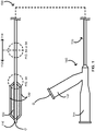
- FIGS. 1 , 4A , and 5A provide schematics illustrating an over-the-wire balloon catheter 100 including at least a pair of scoring wires 130 in accordance with some embodiments.
- the over-the-wire balloon catheter 100 includes an elongate body 110 with a polymeric portion 112 and a metallic portion 114, a balloon 120 over at least some of the polymeric portion 112 of the elongate body 110, and the one or more scoring wires 130.
- the over-the-wire balloon catheter 100 further includes a tip 116 at a distal end of the elongate body 110.
- the over-the-wire balloon catheter 100 can be configured with a guidewire G as shown entering the over-the-wire balloon catheter 100 through a guidewire port 142 in a hub 140 of the over-the-wire balloon catheter 100.
- the hub 140 can also include an inflation port 144 for attaching an inflation device for controlled inflation and deflation of the balloon 120.
- the over-the-wire balloon catheter 100 includes one or more scoring wire ports 413A respectively for the one or more scoring wires 430A.
- the one or more scoring wire ports 413A are located in the polymeric portion 412A of the elongate body 410A on a proximal side of the balloon 420A.
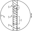
- the over-the-wire balloon catheter 100 includes a coupler 515A formed between the polymeric portion 512A and the metallic portion 514A of the elongate body 510A.
- a proximal end of the polymeric portion 512A of the elongate body 510A can form a male-end connector of the coupler 515A
- a distal end of the metallic portion 514A of the elongate body 510A can form a female-end connector of the coupler 515A - or vice-versa.
- the metallic portion 514A of the elongate body 510A can include a spiral-cut portion 518A configured to act as a spring mechanism to prevent elongation and kinking of the elongate body 510A.
- the one or more scoring wires 530A are fixed respectively at one or more fixation points 532A on an internal surface of the metallic portion 514A of the elongate body 510A such as an internal surface of the spiral-cut portion 518A of the elongate body 510A.
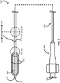
- FIGS. 2 , 4A , and 5A provide schematics illustrating a rapid-exchange balloon catheter 200 including at least a pair of scoring wires 230 in accordance with some embodiments.
- the rapid-exchange balloon catheter 200 includes an elongate body 210 with a polymeric portion 212 and a metallic portion 214, a balloon 220 over at least some of the polymeric portion 212 of the elongate body 210, and the one or more scoring wires 230.
- the rapid-exchange balloon catheter 200 further includes a tip 216 at a distal end of the elongate body 210 and a hub 240 with an inflation port 244 at a proximal end of the elongate body 210.
- the rapid-exchange balloon catheter 200 can be configured with a guidewire G as shown entering the rapid-exchange balloon catheter 200 through a guidewire port 242 of the rapid-exchange balloon catheter 200.
- the guidewire port 242 can be in the polymeric portion 212 of the elongate body 210.
- the rapid-exchange balloon catheter 200 includes one or more scoring wire ports 413A respectively for the one or more scoring wires 430A.
- the one or more scoring wire ports 413A are located in the polymeric portion 412A of the elongate body 410A on a proximal side of the balloon 420A.
- the rapid-exchange balloon catheter 200 includes a coupler 515A formed between the polymeric portion 512A and the metallic portion 514A of the elongate body 510A.
- a proximal end of the polymeric portion 512A of the elongate body 510A can form a male-end connector of the coupler 515A
- a distal end of the metallic portion 514A of the elongate body 510A can form a female-end connector of the coupler 515A - or vice-versa.
- the metallic portion 514A of the elongate body 510A can include a spiral-cut portion 518A configured to act as a spring mechanism to prevent elongation and kinking of the elongate body 510A.
- the one or more scoring wires 530A are fixed respectively at one or more fixation points 532A on an internal surface of the metallic portion 514A of the elongate body 510A such as an internal surface of the spiral-cut portion 518A of the elongate body 510A.
- FIGS. 3A , 4A , and 5A provide schematics illustrating a short rapid-exchange balloon catheter 300A including at least a pair of scoring wires 330A in accordance with some embodiments.
- the short rapid-exchange balloon catheter 300A includes an elongate body 310A with a polymeric portion 312A and a metallic portion 314A, a balloon 320A over at least some of the polymeric portion 312A of the elongate body 310A, and the one or more scoring wires 330A.
- the short rapid-exchange balloon catheter 300A further includes a tip 316A at a distal end of the elongate body 310A and a hub 340A with an inflation port 344A at a proximal end of the elongate body 310A.
- the short rapid-exchange balloon catheter 300A can be configured with a guidewire G entering the short rapid-exchange balloon catheter 300A through a guidewire port 342A in the tip 316A of the short rapid-exchange balloon catheter 300A.
- the short rapid-exchange balloon catheter 300A includes one or more scoring wire ports 413A respectively for the one or more scoring wires 430A.
- the one or more scoring wire ports 413A are located in the polymeric portion 412A of the elongate body 410A on a proximal side of the balloon 420A.
- the short rapid-exchange balloon catheter 300A includes a coupler 515A formed between the polymeric portion 512A and the metallic portion 514A of the elongate body 510A.
- a proximal end of the polymeric portion 512A of the elongate body 510A can form a male-end connector of the coupler 515A
- a distal end of the metallic portion 514A of the elongate body 510A can form a female-end connector of the coupler 515A - or vice-versa.
- the metallic portion 514A of the elongate body 510A can include a spiral-cut portion 518A configured to act as a spring mechanism to prevent elongation and kinking of the elongate body 510A.
- the one or more scoring wires 530A are fixed respectively at one or more fixation points 532A on an internal surface of the metallic portion 514A of the elongate body 510A such as an internal surface of the spiral-cut portion 518A of the elongate body 510A.
- FIGS. 3B , 4B , and 5B provide schematics illustrating a short rapid-exchange balloon catheter 300B including a scoring wire 330B and a guidewire G in accordance with some embodiments.
- the short rapid-exchange balloon catheter 300B includes an elongate body 310B with a polymeric portion 312B and a metallic portion 314B, a balloon 320B over at least some of the polymeric portion 312B of the elongate body 310B, the scoring wire 330B, and the guidewire G configured to function as an additional scoring wire.
- the short rapid-exchange balloon catheter 300B further includes a tip 316B at a distal end of the elongate body 310B and a hub 340B with an inflation port 344B at a proximal end of the elongate body 310B.
- the guidewire G can enter the short rapid-exchange balloon catheter 300B through a guidewire port 342B in the tip 316B of the short rapid-exchange balloon catheter 300B and pass over the balloon 320B as the additional scoring wire.
- the short rapid-exchange balloon catheter 300B includes a scoring wire port 413B for the scoring wire 430B.
- the scoring wire port 413B can be located in the polymeric portion 412B of the elongate body 410B on a proximal side of the balloon 420B. While additional scoring wire ports are not excluded, additional scoring wire ports are not needed in the polymeric portion 412B of the elongate body 410B on account of the guidewire G and its function as the additional scoring wire.
- the short rapid-exchange balloon catheter 300B includes a coupler 515B formed between the polymeric portion 512B and the metallic portion 514B of the elongate body 510B.
- a proximal end of the polymeric portion 512B of the elongate body 510B can form a male-end connector of the coupler 515B, and a distal end of the metallic portion 514B of the elongate body 510B can form a female-end connector of the coupler 515B - or vice-versa.
- the metallic portion 514B of the elongate body 510B can include a spiral-cut portion 518B configured to act as a spring mechanism to prevent elongation and kinking of the elongate body 510B.
- the scoring wire 530B is fixed at a fixation point 532B on an internal surface of the metallic portion 514B of the elongate body 510B such as an internal surface of the spiral-cut portion 518B of the elongate body 510B.
- Each of the one or more scoring wires can be separately formed and subsequently fixed by its free ends to a catheter.
- the one or more scoring wires of the over-the-wire balloon catheter 100, the rapid-exchange balloon catheter 200, and the short rapid-exchange balloon catheter 300A, respectively, extend from the tip at the distal end of the elongate body and over the balloon.
- the one or more scoring wires 430A extend through the polymeric portion 412A of the elongate body 410A.
- the one or more scoring wires 530A extend through at least a first coupler such as the coupler 515A, and to the metallic portion 514A of the elongate body.
- each scoring wire of a pair of scoring wires can extend from the tip at the distal end of the elongate body, over an opposing side of the balloon, through a scoring wire port in an opposing side of the polymeric portion of the elongate body, through at least a portion of a lumen of the polymeric portion of the elongate body, through a lumen of the coupler, and into a lumen of the metallic portion of the elongate body.
- the one or more scoring wires are fixed to the tip of the elongate body (see FIGS.
- the internal surface of the metallic portion of the elongate body to which each scoring wire of the one or more scoring wires are fixed can be a luminal surface of the spiral-cut portion of the metallic portion of the elongate body.
- the scoring wire 330B of the short rapid-exchange balloon catheter 300B extends from the tip at the distal end of the elongate body 310B and over the balloon 320B.
- the guidewire G can also extend from the guidewire port in the tip 316B at the distal end of the elongate body 310B and over the balloon 320B.
- the scoring wire 430B extends through the polymeric portion 412B of the elongate body 410B.
- the scoring wire 530B extends through at least a first coupler such as the coupler 515B, and to the metallic portion 514B of the elongate body 510B.
- the scoring wire 530B extends from the tip 316B ( FIG. 3B ) at the distal end of the elongate body 510B, over an opposing side of the balloon 320B ( FIG. 3B ) from the guidewire G , when present, through a scoring wire port in the polymeric portion 512B of the elongate body 510B, through at least a portion of a lumen of the polymeric portion 512B of the elongate body 510B, through a lumen of the coupler 515B, and into a lumen of the metallic portion 514B of the elongate body 510B.
- the scoring wire 530B is fixed to the tip 316B ( FIG.
- the internal surface of the metallic portion 514B of the elongate body 510B to which the scoring wire 530B is fixed can be a luminal surface of the spiral-cut portion of the metallic portion 514B of the elongate body 510B.
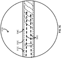
- the one or more scoring wires 530A of FIG. 5A or the scoring wire 530B of FIG. 5B can further extend through a second coupler 519C shown in FIG. 5C for the one or more scoring wires 530C.
- the second coupler 519C can include a polymeric sleeve over the polymeric portion 512C and the metallic portion 514C of the elongate body 510C, and, thus, over the coupler 515C (not shown) as well.
- the polymeric sleeve can be a heat-shrunken polymeric sleeve of a biocompatible material such as polytetrafluoroethylene (“PTFE").
- the manner in which the one or more scoring wires 530A are fixed to the tip 316A ( FIG. 3A ) of the elongate body 510A and the internal surface of the metallic portion 514A of the elongate body 510A is not limited.
- a spot weld such as a laser spot weld can fix each of the one or more scoring wires 530A to at least the internal surface of the metallic portion 514A of the elongate body 510A.
- the guidewire G is not fixed to the tip 316B ( FIG. 3B ) of the elongate body 510B or the internal surface of the metallic portion 514B of the elongate body 510B.
- At least one scoring wire of the one or more scoring wires can include radiopaque markers configured for radiographic delineation of a working length of the balloon.
- each of the one or more scoring wires can be formed from the spiral-cut portion of the metallic portion of the elongate body and subsequently fixed by its free end to a catheter.
- the one or more scoring wires of the over-the-wire balloon catheter 100, the rapid-exchange balloon catheter 200, and the short rapid-exchange balloon catheter 300A, respectively, can extend from the tip at the distal end of the elongate body and over the balloon.
- the one or more scoring wires 430A can extend through the polymeric portion 412A of the elongate body 410A.
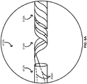
- the one or more scoring wires 630A can emerge from the polymeric portion 612A and form into the spiral-cut portion 618 A of the metallic portion 614A of the elongate body 610A.
- each scoring wire of a pair of scoring wires can extend from the tip at the distal end of the elongate body, over an opposing side of the balloon, through a scoring wire port in an opposing side of the polymeric portion of the elongate body, through at least a portion of a lumen of the polymeric portion of the elongate body, and form into the spiral-cut portion of the metallic portion of the elongate body.
- the one or more scoring wires can be drawn out or otherwise formed from the spiral-cut portion and fixed to the tip of the elongate body (see FIGS. 1 , 2 , and 3A respectively for the over-the-wire balloon catheter 100, the rapid-exchange balloon catheter 200, and the short rapid-exchange balloon catheter 300A).
- the one or more scoring wires 630A can be formed from the metallic portion 614A respectively with one or more spiral cuts in the metallic portion 614A. As shown in FIG. 6A , for example, two longitudinally offset spiral cuts provides two scoring wires.
- the scoring wire 330B of the short rapid-exchange balloon catheter 300B can extend from the tip at the distal end of the elongate body 310B and over the balloon 320B.
- the guidewire G can also extend from the guidewire port in the tip 316B at the distal end of the elongate body 310B and over the balloon 320B.
- the scoring wire 430B can extend through the polymeric portion 412B of the elongate body 410B.
- the scoring wire 630B can emerge from the polymeric portion 612B and form into the spiral-cut portion 618B of the metallic portion 614B of the elongate body 610B.
- the scoring wire 630B can extend from the tip 316B ( FIG. 3B ) at the distal end of the elongate body 610B, over an opposing side of the balloon 320B ( FIG. 3B ) from the guidewire G , when present, through a scoring wire port in the polymeric portion 412B ( FIG. 4B ) of the elongate body 610B, through at least a portion of a lumen of the polymeric portion 612B of the elongate body 610B, and form into the spiral-cut portion 618B of the metallic portion 614B of the elongate body 610B.
- the scoring wire can be drawn out or otherwise formed from the spiral-cut portion and fixed to the tip of the elongate body (see FIGS. 1 , 2 , and 3A respectively for the over-the-wire balloon catheter 100, the rapid-exchange balloon catheter 200, and the short rapid-exchange balloon catheter 300A).
- the one or more scoring wires 630A of FIG. 6A or the scoring wire 630B of FIG. 6B can further extend through a coupler 619C shown in FIG. 6C for the one or more scoring wires 630C.
- the coupler 619C can include a polymeric sleeve over the polymeric portion 612C and the metallic portion 614C of the elongate body 610C.
- the polymeric sleeve can be a heat-shrunken polymeric sleeve of a biocompatible material such as polytetrafluoroethylene (“PTFE").
- the manner in which the one or more scoring wires 730A are fixed to the tip 316A ( FIG. 3A ) of the elongate body 710A is not limited.
- the guidewire G is used as a scoring wire in the short rapid-exchange balloon catheter 300B, the guidewire G is not fixed to the tip 316B ( FIG. 3B ) of the elongate body 510B.
- At least one scoring wire of the one or more scoring wires can include radiopaque markers configured for radiographic delineation of a working length of the balloon.
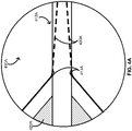
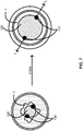
- FIG. 7 provides a schematic illustrating modification of an intravascular lesion.
- a balloon catheter such as the over-the-wire balloon catheter 100, the rapid-exchange balloon catheter 200, or one of the short rapid-exchange balloon catheters 300A or 300B can be advanced through a patient's vasculature until the balloon (e.g., the balloon 120) and the one or more scoring wires (e.g., the one or more scoring wires 130) are in a position alongside an intravascular lesion L. Inflation of the balloon in such a position provides outwardly focused forces f 1 and f 2 against the lesion L along the one or more scoring wires over a length of the balloon, thereby restoring patency lost to the intravascular L.
- the balloon e.g., the balloon 120
- the one or more scoring wires e.g., the one or more scoring wires 130
- the forces f 1 and f 2 can increase from a minimum when the balloon is in an uninflated or minimally inflated state to a maximum when the balloon is in a fully inflated state.
- the foregoing can be effected in vasculature of various sizes and tortuosities.
- the balloon and the one or more scoring wires are sufficiently flexible to modify intravascular lesions in curved vasculature.
- a balloon catheter such as the over-the-wire balloon catheter 100, the rapid exchange balloon catheter 200, or one of the short rapid-exchange balloon catheters 300A or 300B can be used to dilate stenoses in the iliac, femoral, ilio-femoral, popliteal, infra-popliteal, and renal arteries and to treat obstructive lesions of native or synthetic arterioveneous dialysis fistulae.
- the balloon catheter can also be used for post dilatation of balloon-expandable stents, self-expanding stents, and stent grafts in the peripheral vasculature.
- a balloon catheter such as the over-the-wire balloon catheter 100, the rapid exchange balloon catheter 200, or one of the short rapid-exchange balloon catheters 300A or 300B is used in a system with an inflation device configured to inflate the balloon of the balloon catheter.
- an inflation device can include a piston pump, a manometer, high-pressure tubing configured to tolerate pressures of at least 40 atm, and an adapter configured to connect with the hub at the proximal end of the elongate body of the balloon catheter.
- the inflation device is a CALIBER ® Inflation Device or the PRESTO ® Inflation Device by Bard Peripheral Vascular, Inc. of Tempe, Arizona.
- a catheter including an elongate body with a polymeric portion and a metallic portion, a balloon over at least some of the polymeric portion of the elongate body, a coupler formed between the polymeric and metallic portions of the elongate body, and one or more scoring wires.
- the one or more scoring wires extend from a tip at a distal end of the elongate body, over the balloon, through the polymeric portion of the elongate body, through the coupler, and to the metallic portion of the elongate body.
- the one or more scoring wires are fixed to the tip of the elongate body as well as an internal surface of the metallic portion of the elongate body proximate to the coupler.
- Claim 1 does not recite that the internal surface of the metallic portion of the elongate body to which each scoring wire of the pair of scoring wires can be fixed can be a luminal surface of a spiral-cut portion of the metallic portion of the elongate body.
- the metallic portion of the elongate body can include a spiral-cut portion configured to act as a spring mechanism to prevent elongation and kinking of the spiral-cut portion.
- a proximal end of the polymeric portion of the elongate body can form a male-end connector of the coupler, and a distal end of the metallic portion of the elongate body can form a female-end connector of the coupler.
- the one or more scoring wires can be at least a pair of scoring wires, and each scoring wire of the pair of scoring wires can pass over an opposing side of the balloon.
- each scoring wire of the pair of scoring wires can pass through a scoring wire port in an opposing side of the polymeric portion of the elongate body as well as at least a portion of a lumen of the polymeric portion of the elongate body.
- each scoring wire of the pair of scoring wires can further pass through a lumen of the coupler as well as at least a portion of a lumen of the metallic portion of the elongate body.
- at least one scoring wire of the one or more scoring wires can include radiopaque markers configured for radiographic delineation of a working length of the balloon.
- the one or more scoring wires can be configured to provide an outwardly focused force along a length of the balloon when the balloon is in an inflated state even at a low inflation level.
- the one or more scoring wires and the balloon can be sufficiently flexible to modify intravascular lesions in curved vasculature when the balloon is in an inflated state.
- the catheter can be configured as an over-the-wire catheter with a guidewire port in a hub at a proximal end of the elongate body.
- the catheter can be configured as a rapid-exchange catheter with a guidewire port in the polymeric portion of the elongate body between the balloon and the coupler.
- the catheter can be configured as a short rapid-exchange catheter with a guidewire port in the tip of the elongate body.
- a catheter including an elongate body with a polymeric portion and a metallic portion; a balloon over at least some of the polymeric portion of the elongate body; a coupler over the polymeric and metallic portions of the elongate body; and one or more scoring wires.
- the metallic portion of the elongate body may optionally include a spiral-cut portion configured to prevent elongation and kinking of the elongate body.
- the one or more scoring wire extend from a tip at a distal end of the elongate body, over the balloon, through the polymeric portion, through the coupler, and to the metallic portion.
- the one or more scoring wires can be formed from the spiral-cut portion of the metallic portion and fixed to the tip at the distal end of the elongate body.
- each wire of the one or more scoring wire may result from a separate spiral cut longitudinally offset from any other spiral cut in the spiral-cut portion.
- a catheter including an elongate body including a polymeric portion and a metallic portion, a balloon over at least some of the polymeric portion of the elongate body, a coupler formed between the polymeric and metallic portions of the elongate body, and at least a pair of scoring wires.
- the metallic portion of the elongate body can include a spiral-cut portion configured to act as a spring mechanism to prevent elongation and kinking of the spiral-cut portion.
- the coupler can include a male-end connector and a female-end connector, wherein the male-end connector can be formed from a proximal end of the polymeric portion of the elongate body, and wherein the female-end connector can be formed from a distal end of the metallic portion of the elongate body.
- Each scoring wire of the pair of scoring wires can extend from a tip at a distal end of the elongate body, over an opposing side of the balloon, through a scoring wire port in an opposing side of the polymeric portion of the elongate body, through a lumen of the polymeric portion of the elongate body, through a lumen of the coupler, and into a lumen of the metallic portion of the elongate body.
- the one or more scoring wires are fixed to the tip of the elongate body as well as an internal surface of the metallic portion proximate to the coupler.
- the one or more scoring wires can be configured to provide an outwardly focused force along a length of the balloon when the balloon is in an inflated state even at a low inflation level.
- the one or more scoring wires and the balloon can be sufficiently flexible to modify intravascular lesions in curved vasculature when the balloon is in an inflated state.
- at least one scoring wire of the one or more scoring wires can include radiopaque markers configured for radiographic delineation of a working length of the balloon.
- the catheter can be configured as a rapid-exchange catheter with a guidewire port in the polymeric portion of the elongate body between the balloon and the coupler.
- the catheter can be configured as a short rapid-exchange catheter with a guidewire port in the tip of the elongate body, and the guidewire through the guidewire port can be one scoring wire of the pair of scoring wires.
- the invention is also directed to a system including a catheter and an inflation device.
- the catheter includes an elongate body with a polymeric portion and a metallic portion, a balloon over at least some of the polymeric portion of the elongate body, a coupler formed between the polymeric and metallic portions of the elongate body, and one or more scoring wires.
- the metallic portion of the elongate body can include a spiral-cut portion configured to act as a spring mechanism to prevent elongation and kinking of the elongate body.
- the one or more scoring wire extend from a tip at a distal end of the elongate body, over the balloon, through the polymeric portion of the elongate body, through the coupler, and to the metallic portion of the elongate body.
- the one or more scoring wires are fixed to the tip of the elongate body as well as an internal surface of the metallic portion proximate to the coupler.
- the inflation device is configured to inflate the balloon of the catheter.
- the inflation device can include a piston pump, a manometer, high-pressure tubing configured to tolerate pressures of at least 40 atm, and an adapter configured to connect with a hub at a proximal end of the elongate body of the catheter.
Landscapes
- Health & Medical Sciences (AREA)
- Life Sciences & Earth Sciences (AREA)
- Heart & Thoracic Surgery (AREA)
- Animal Behavior & Ethology (AREA)
- Veterinary Medicine (AREA)
- Public Health (AREA)
- Engineering & Computer Science (AREA)
- Biomedical Technology (AREA)
- General Health & Medical Sciences (AREA)
- Anesthesiology (AREA)
- Hematology (AREA)
- Pulmonology (AREA)
- Biophysics (AREA)
- Child & Adolescent Psychology (AREA)
- Vascular Medicine (AREA)
- Surgery (AREA)
- Nuclear Medicine, Radiotherapy & Molecular Imaging (AREA)
- Medical Informatics (AREA)
- Molecular Biology (AREA)
- Media Introduction/Drainage Providing Device (AREA)
Claims (14)
- Cathéter (100 ; 200 ; 300A ; 300B), comprenant :un corps allongé (110) incluant une portion polymère (112) et une portion métallique (114) ;un ballonnet (120) sur au moins une partie de la portion polymère (112) ;un coupleur (515A) formé entre les portions polymère (112) et métallique (114) ; etun ou plusieurs fils inciseurs (430A) s'étendant d'une pointe (116) au niveau d'une extrémité distale du corps allongé (110), sur le ballonnet (120), à travers la portion polymère (112), à travers le coupleur (515A), et à la portion métallique (114), dans lequel les un ou plusieurs fils inciseurs (430A) sont fixés à la pointe (116) et à une surface interne de la portion métallique (114) à proximité du coupleur (515A).
- Cathéter selon la revendication 1, dans lequel la portion métallique (114) inclut une portion découpée en spirale (618A) configurée pour empêcher l'allongement et l'entortillement du corps allongé (110).
- Cathéter selon la revendication 1 ou 2, dans lequel :une extrémité proximale de la portion polymère (112) forme un connecteur à extrémité mâle du coupleur (515A) ; etune extrémité distale de la portion métallique (114) forme un connecteur à extrémité femelle du coupleur (515A).
- Cathéter selon l'une quelconque des revendications précédentes, dans lequel :les un ou plusieurs fils inciseurs (330A) sont au moins une paire de fils inciseurs, etchaque fil inciseur de la paire de fils inciseurs passe sur un côté opposé du ballonnet.
- Cathéter selon la revendication 4, dans lequel chaque fil inciseur (330A) de la paire de fils inciseurs passe à travers un orifice de fil inciseur (413A) dans un côté opposé de la portion polymère et au moins une portion d'une lumière de la portion polymère.
- Cathéter selon la revendication 4 ou 5, dans lequel :chaque fil inciseur (330A) de la paire de fils inciseurs passe en outre à travers une lumière du coupleur (515B) et au moins une portion d'une lumière de la portion métallique (114) ; etla surface interne de la portion métallique (114) à laquelle chaque fil inciseur (330A) de la paire de fils inciseurs est fixé est une surface luminale de la portion découpée en spirale de la portion métallique.
- Cathéter selon l'une quelconque des revendications précédentes, dans lequel au moins un fil inciseur (430A) des un ou plusieurs fils inciseurs inclut des marqueurs radio-opaques configurés pour une délimitation radiographique d'une longueur utile du ballonnet.
- Cathéter selon l'une quelconque des revendications précédentes, dans lequel les un ou plusieurs fils inciseurs (430A) sont configurés pour fournir une force concentrée vers l'extérieur sur une longueur du ballonnet (120) lorsque le ballonnet est dans un état gonflé.
- Cathéter selon l'une quelconque des revendications précédentes, dans lequel les un ou plusieurs fils inciseurs (430A) et le ballonnet (120) sont suffisamment souples pour modifier des lésions intravasculaires dans un système vasculaire incurvé lorsque le ballonnet est dans un état gonflé.
- Cathéter selon l'une quelconque des revendications 1-9, dans lequel le cathéter (100) est configuré sous forme d'un cathéter sur guide avec un orifice de fil-guide (142) dans une embase (140) au niveau d'une extrémité proximale du corps allongé (110).
- Cathéter selon l'une quelconque des revendications 1-9, dans lequel le cathéter (200) est configuré sous forme d'un cathéter à échange rapide avec un orifice de fil-guide (242) dans la portion polymère (212) entre le ballonnet (220) et le coupleur (515A).
- Cathéter selon l'une quelconque des revendications 1-9, dans lequel le cathéter (300A, 300B) est configuré sous forme d'un cathéter court à échange rapide avec un orifice de fil-guide (342A) dans la pointe (316A).
- Système, comprenant :a) un cathéter (100 ; 200; 300A ; 300B) selon l'une quelconque des revendications précédentes, dans lequel la portion métallique (114) inclut une portion découpée en spirale (618A) configurée pour empêcher l'allongement et l'entortillement du corps allongé (110) ; et dans lequel les un ou plusieurs fils inciseurs (430A) sont fixés à la pointe (116) et à une surface interne de la portion découpée en spirale (618A) à proximité du coupleur (515A) ; etb) un dispositif de gonflage configuré pour gonfler le ballonnet.
- Système selon la revendication 13, dans lequel le dispositif de gonflage comprend une pompe à piston, un manomètre, une tubulure haute pression configurée pour résister à des pressions d'au moins 40 atm, et un adaptateur configuré pour se connecter à une embase (140) au niveau d'une extrémité proximale du corps allongé (100) du cathéter.
Priority Applications (1)
| Application Number | Priority Date | Filing Date | Title |
|---|---|---|---|
| EP21200885.8A EP3988155B1 (fr) | 2016-12-16 | 2017-12-12 | Cathéters à ballonnet |
Applications Claiming Priority (2)
| Application Number | Priority Date | Filing Date | Title |
|---|---|---|---|
| US201662435223P | 2016-12-16 | 2016-12-16 | |
| PCT/US2017/065839 WO2018111889A1 (fr) | 2016-12-16 | 2017-12-12 | Cathéters à ballonnet et procédés associés |
Related Child Applications (2)
| Application Number | Title | Priority Date | Filing Date |
|---|---|---|---|
| EP21200885.8A Division-Into EP3988155B1 (fr) | 2016-12-16 | 2017-12-12 | Cathéters à ballonnet |
| EP21200885.8A Division EP3988155B1 (fr) | 2016-12-16 | 2017-12-12 | Cathéters à ballonnet |
Publications (3)
| Publication Number | Publication Date |
|---|---|
| EP3554612A1 EP3554612A1 (fr) | 2019-10-23 |
| EP3554612A4 EP3554612A4 (fr) | 2020-10-14 |
| EP3554612B1 true EP3554612B1 (fr) | 2023-01-25 |
Family
ID=62559211
Family Applications (2)
| Application Number | Title | Priority Date | Filing Date |
|---|---|---|---|
| EP17879736.1A Active EP3554612B1 (fr) | 2016-12-16 | 2017-12-12 | Cathéters à ballonnet |
| EP21200885.8A Active EP3988155B1 (fr) | 2016-12-16 | 2017-12-12 | Cathéters à ballonnet |
Family Applications After (1)
| Application Number | Title | Priority Date | Filing Date |
|---|---|---|---|
| EP21200885.8A Active EP3988155B1 (fr) | 2016-12-16 | 2017-12-12 | Cathéters à ballonnet |
Country Status (9)
| Country | Link |
|---|---|
| US (1) | US10595894B2 (fr) |
| EP (2) | EP3554612B1 (fr) |
| JP (1) | JP6978503B2 (fr) |
| KR (1) | KR102520161B1 (fr) |
| CN (1) | CN110248692A (fr) |
| AU (1) | AU2017375945B2 (fr) |
| CA (1) | CA3047273C (fr) |
| MX (1) | MX390824B (fr) |
| WO (1) | WO2018111889A1 (fr) |
Families Citing this family (2)
| Publication number | Priority date | Publication date | Assignee | Title |
|---|---|---|---|---|
| CN114502229B (zh) * | 2019-10-15 | 2024-09-20 | 美敦力瓦斯科尔勒公司 | 用于球囊导管型装置的保护装置和方法 |
| WO2021251980A1 (fr) * | 2020-06-12 | 2021-12-16 | C.R. Bard, Inc. | Cathéter à ballonnet avec fonction de notation sélective |
Family Cites Families (27)
| Publication number | Priority date | Publication date | Assignee | Title |
|---|---|---|---|---|
| US5904679A (en) * | 1989-01-18 | 1999-05-18 | Applied Medical Resources Corporation | Catheter with electrosurgical cutter |
| US5217434A (en) * | 1991-10-15 | 1993-06-08 | Scimed Life Systems, Inc. | Innerless dilatation catheter with balloon stretch valve |
| CA2137116A1 (fr) * | 1994-01-07 | 1995-07-08 | Todd A. Berg | Joint de catheter a contre-alesage |
| US5549552A (en) * | 1995-03-02 | 1996-08-27 | Scimed Life Systems, Inc. | Balloon dilation catheter with improved pushability, trackability and crossability |
| US20050177130A1 (en) * | 2004-02-10 | 2005-08-11 | Angioscore, Inc. | Balloon catheter with spiral folds |
| US20050209673A1 (en) * | 2004-03-04 | 2005-09-22 | Y Med Inc. | Bifurcation stent delivery devices |
| US7527606B2 (en) * | 2004-05-27 | 2009-05-05 | Abbott Laboratories | Catheter having main body portion with coil-defined guidewire passage |
| JP2009509622A (ja) * | 2005-10-03 | 2009-03-12 | ワイ メッド インク | 血管治療装置 |
| US7678223B2 (en) * | 2006-04-17 | 2010-03-16 | Boston Scientific Scimed, Inc. | Catheter having a multi-section tubular member and method of making the same |
| US8382738B2 (en) * | 2006-06-30 | 2013-02-26 | Abbott Cardiovascular Systems, Inc. | Balloon catheter tapered shaft having high strength and flexibility and method of making same |
| US8657845B2 (en) * | 2007-05-15 | 2014-02-25 | Cook Medical Technologies Llc | Multifilar cable catheter |
| CN101409385A (zh) * | 2007-10-11 | 2009-04-15 | 肖立群 | 一种射频电缆内导体管的管连接结构 |
| FR2923721B1 (fr) * | 2007-11-20 | 2011-04-08 | Sedat | Dispositif de gonflage de ballonnet. |
| CN201564947U (zh) * | 2009-10-30 | 2010-09-01 | 业聚医疗器械(深圳)有限公司 | 球囊导管 |
| CN201596232U (zh) * | 2009-12-28 | 2010-10-06 | 业聚医疗器械(深圳)有限公司 | 球囊导管 |
| JP5580279B2 (ja) * | 2011-11-29 | 2014-08-27 | 日本ライフライン株式会社 | バルーンカテーテル |
| CN202510875U (zh) * | 2012-04-06 | 2012-10-31 | 杨新才 | 缠绕管接头结构 |
| JP2014069035A (ja) | 2012-10-02 | 2014-04-21 | Nipro Corp | バルーンカテーテル |
| CN203090196U (zh) * | 2013-01-25 | 2013-07-31 | 业聚医疗器械(深圳)有限公司 | 球囊导管 |
| US9320530B2 (en) | 2013-03-13 | 2016-04-26 | The Spectranetics Corporation | Assisted cutting balloon |
| CN203208508U (zh) * | 2013-04-15 | 2013-09-25 | 业聚医疗器械(深圳)有限公司 | 快速交换球囊导管结构 |
| US9808276B2 (en) * | 2013-04-25 | 2017-11-07 | Invatec S.P.A. | Angioplasty balloon having selectively deployable cutting or scoring element and related methods |
| US10117668B2 (en) * | 2013-10-08 | 2018-11-06 | The Spectranetics Corporation | Balloon catheter with non-deployable stent having improved stability |
| CN204391293U (zh) * | 2014-11-04 | 2015-06-10 | 江苏通华机电成套有限公司 | 内置嵌入式管母线中间接头 |
| JP6342843B2 (ja) * | 2015-05-01 | 2018-06-13 | 朝日インテック株式会社 | バルーンカテーテル |
| CN204766984U (zh) * | 2015-07-09 | 2015-11-18 | 深圳脉动医学技术有限公司 | 一种防滑球囊导管 |
| CN105664338A (zh) * | 2016-04-26 | 2016-06-15 | 业聚医疗器械(深圳)有限公司 | 球囊导管 |
-
2017
- 2017-12-12 MX MX2019006972A patent/MX390824B/es unknown
- 2017-12-12 WO PCT/US2017/065839 patent/WO2018111889A1/fr not_active Ceased
- 2017-12-12 CN CN201780084584.7A patent/CN110248692A/zh active Pending
- 2017-12-12 EP EP17879736.1A patent/EP3554612B1/fr active Active
- 2017-12-12 EP EP21200885.8A patent/EP3988155B1/fr active Active
- 2017-12-12 JP JP2019531896A patent/JP6978503B2/ja active Active
- 2017-12-12 KR KR1020197020208A patent/KR102520161B1/ko active Active
- 2017-12-12 AU AU2017375945A patent/AU2017375945B2/en active Active
- 2017-12-12 CA CA3047273A patent/CA3047273C/fr active Active
- 2017-12-12 US US16/469,206 patent/US10595894B2/en active Active
Also Published As
| Publication number | Publication date |
|---|---|
| MX2019006972A (es) | 2019-08-22 |
| CA3047273A1 (fr) | 2018-06-21 |
| KR20190095369A (ko) | 2019-08-14 |
| KR102520161B1 (ko) | 2023-04-07 |
| JP2020501704A (ja) | 2020-01-23 |
| CA3047273C (fr) | 2020-08-25 |
| US10595894B2 (en) | 2020-03-24 |
| WO2018111889A1 (fr) | 2018-06-21 |
| AU2017375945A1 (en) | 2019-07-11 |
| NZ754864A (en) | 2025-02-28 |
| MX390824B (es) | 2025-03-21 |
| US20190380738A1 (en) | 2019-12-19 |
| AU2017375945B2 (en) | 2019-10-10 |
| CN110248692A (zh) | 2019-09-17 |
| EP3988155A1 (fr) | 2022-04-27 |
| EP3554612A4 (fr) | 2020-10-14 |
| JP6978503B2 (ja) | 2021-12-08 |
| EP3988155C0 (fr) | 2024-07-24 |
| EP3554612A1 (fr) | 2019-10-23 |
| EP3988155B1 (fr) | 2024-07-24 |
Similar Documents
| Publication | Publication Date | Title |
|---|---|---|
| US8419679B2 (en) | Embolic protection systems for bifurcated conduits | |
| US6083232A (en) | Vibrating stent for opening calcified lesions | |
| US7396358B2 (en) | Device and method for converting a balloon catheter into a cutting balloon catheter | |
| US7427288B2 (en) | Mechanically expandable distal protection apparatus and method of use | |
| US7597703B2 (en) | Mechanically expandable occluder | |
| US20020055733A1 (en) | Catheter assembly and method of use | |
| US12472333B2 (en) | Mobile balloon support catheter | |
| EP3554612B1 (fr) | Cathéters à ballonnet | |
| JP7057832B2 (ja) | 二重アクセス切開カテーテル | |
| US10092430B2 (en) | Balloon with mandrel support guidewire | |
| US20190142571A1 (en) | Branching covered stent-grafts and related deployment systems and methods | |
| EP3554614A1 (fr) | Ballonnets médicaux, cathéters à ballonnet et méthodes associées | |
| JP2008000276A (ja) | カテーテル用拡張体及び拡張カテーテル | |
| US20250295894A1 (en) | Balloon catheter-stent structure combination | |
| Lee | Bent stents: A method to facilitate delivery of the Palmaz‐Schatz stent in tortuous and rigid coronary arteries | |
| Tyagi | Cutting balloon angioplasty |
Legal Events
| Date | Code | Title | Description |
|---|---|---|---|
| STAA | Information on the status of an ep patent application or granted ep patent |
Free format text: STATUS: THE INTERNATIONAL PUBLICATION HAS BEEN MADE |
|
| PUAI | Public reference made under article 153(3) epc to a published international application that has entered the european phase |
Free format text: ORIGINAL CODE: 0009012 |
|
| STAA | Information on the status of an ep patent application or granted ep patent |
Free format text: STATUS: REQUEST FOR EXAMINATION WAS MADE |
|
| 17P | Request for examination filed |
Effective date: 20190709 |
|
| AK | Designated contracting states |
Kind code of ref document: A1 Designated state(s): AL AT BE BG CH CY CZ DE DK EE ES FI FR GB GR HR HU IE IS IT LI LT LU LV MC MK MT NL NO PL PT RO RS SE SI SK SM TR |
|
| AX | Request for extension of the european patent |
Extension state: BA ME |
|
| DAV | Request for validation of the european patent (deleted) | ||
| DAX | Request for extension of the european patent (deleted) | ||
| A4 | Supplementary search report drawn up and despatched |
Effective date: 20200914 |
|
| RIC1 | Information provided on ipc code assigned before grant |
Ipc: A61B 17/3207 20060101ALI20200908BHEP Ipc: A61M 25/10 20130101AFI20200908BHEP Ipc: A61M 25/01 20060101ALI20200908BHEP Ipc: A61M 25/00 20060101ALI20200908BHEP |
|
| GRAP | Despatch of communication of intention to grant a patent |
Free format text: ORIGINAL CODE: EPIDOSNIGR1 |
|
| STAA | Information on the status of an ep patent application or granted ep patent |
Free format text: STATUS: GRANT OF PATENT IS INTENDED |
|
| INTG | Intention to grant announced |
Effective date: 20210525 |
|
| GRAJ | Information related to disapproval of communication of intention to grant by the applicant or resumption of examination proceedings by the epo deleted |
Free format text: ORIGINAL CODE: EPIDOSDIGR1 |
|
| STAA | Information on the status of an ep patent application or granted ep patent |
Free format text: STATUS: REQUEST FOR EXAMINATION WAS MADE |
|
| INTC | Intention to grant announced (deleted) | ||
| STAA | Information on the status of an ep patent application or granted ep patent |
Free format text: STATUS: EXAMINATION IS IN PROGRESS |
|
| 17Q | First examination report despatched |
Effective date: 20211220 |
|
| GRAP | Despatch of communication of intention to grant a patent |
Free format text: ORIGINAL CODE: EPIDOSNIGR1 |
|
| STAA | Information on the status of an ep patent application or granted ep patent |
Free format text: STATUS: GRANT OF PATENT IS INTENDED |
|
| INTG | Intention to grant announced |
Effective date: 20220818 |
|
| RAP3 | Party data changed (applicant data changed or rights of an application transferred) |
Owner name: C. R. BARD, INC. |
|
| GRAS | Grant fee paid |
Free format text: ORIGINAL CODE: EPIDOSNIGR3 |
|
| GRAA | (expected) grant |
Free format text: ORIGINAL CODE: 0009210 |
|
| STAA | Information on the status of an ep patent application or granted ep patent |
Free format text: STATUS: THE PATENT HAS BEEN GRANTED |
|
| AK | Designated contracting states |
Kind code of ref document: B1 Designated state(s): AL AT BE BG CH CY CZ DE DK EE ES FI FR GB GR HR HU IE IS IT LI LT LU LV MC MK MT NL NO PL PT RO RS SE SI SK SM TR |
|
| REG | Reference to a national code |
Ref country code: GB Ref legal event code: FG4D |
|
| REG | Reference to a national code |
Ref country code: CH Ref legal event code: EP |
|
| REG | Reference to a national code |
Ref country code: AT Ref legal event code: REF Ref document number: 1545527 Country of ref document: AT Kind code of ref document: T Effective date: 20230215 Ref country code: IE Ref legal event code: FG4D |
|
| REG | Reference to a national code |
Ref country code: DE Ref legal event code: R096 Ref document number: 602017065831 Country of ref document: DE |
|
| REG | Reference to a national code |
Ref country code: LT Ref legal event code: MG9D |
|
| REG | Reference to a national code |
Ref country code: NL Ref legal event code: MP Effective date: 20230125 |
|
| REG | Reference to a national code |
Ref country code: AT Ref legal event code: MK05 Ref document number: 1545527 Country of ref document: AT Kind code of ref document: T Effective date: 20230125 |
|
| PG25 | Lapsed in a contracting state [announced via postgrant information from national office to epo] |
Ref country code: NL Free format text: LAPSE BECAUSE OF FAILURE TO SUBMIT A TRANSLATION OF THE DESCRIPTION OR TO PAY THE FEE WITHIN THE PRESCRIBED TIME-LIMIT Effective date: 20230125 |
|
| PG25 | Lapsed in a contracting state [announced via postgrant information from national office to epo] |
Ref country code: RS Free format text: LAPSE BECAUSE OF FAILURE TO SUBMIT A TRANSLATION OF THE DESCRIPTION OR TO PAY THE FEE WITHIN THE PRESCRIBED TIME-LIMIT Effective date: 20230125 Ref country code: PT Free format text: LAPSE BECAUSE OF FAILURE TO SUBMIT A TRANSLATION OF THE DESCRIPTION OR TO PAY THE FEE WITHIN THE PRESCRIBED TIME-LIMIT Effective date: 20230525 Ref country code: NO Free format text: LAPSE BECAUSE OF FAILURE TO SUBMIT A TRANSLATION OF THE DESCRIPTION OR TO PAY THE FEE WITHIN THE PRESCRIBED TIME-LIMIT Effective date: 20230425 Ref country code: LV Free format text: LAPSE BECAUSE OF FAILURE TO SUBMIT A TRANSLATION OF THE DESCRIPTION OR TO PAY THE FEE WITHIN THE PRESCRIBED TIME-LIMIT Effective date: 20230125 Ref country code: LT Free format text: LAPSE BECAUSE OF FAILURE TO SUBMIT A TRANSLATION OF THE DESCRIPTION OR TO PAY THE FEE WITHIN THE PRESCRIBED TIME-LIMIT Effective date: 20230125 Ref country code: HR Free format text: LAPSE BECAUSE OF FAILURE TO SUBMIT A TRANSLATION OF THE DESCRIPTION OR TO PAY THE FEE WITHIN THE PRESCRIBED TIME-LIMIT Effective date: 20230125 Ref country code: ES Free format text: LAPSE BECAUSE OF FAILURE TO SUBMIT A TRANSLATION OF THE DESCRIPTION OR TO PAY THE FEE WITHIN THE PRESCRIBED TIME-LIMIT Effective date: 20230125 Ref country code: AT Free format text: LAPSE BECAUSE OF FAILURE TO SUBMIT A TRANSLATION OF THE DESCRIPTION OR TO PAY THE FEE WITHIN THE PRESCRIBED TIME-LIMIT Effective date: 20230125 |
|
| PG25 | Lapsed in a contracting state [announced via postgrant information from national office to epo] |
Ref country code: SE Free format text: LAPSE BECAUSE OF FAILURE TO SUBMIT A TRANSLATION OF THE DESCRIPTION OR TO PAY THE FEE WITHIN THE PRESCRIBED TIME-LIMIT Effective date: 20230125 Ref country code: PL Free format text: LAPSE BECAUSE OF FAILURE TO SUBMIT A TRANSLATION OF THE DESCRIPTION OR TO PAY THE FEE WITHIN THE PRESCRIBED TIME-LIMIT Effective date: 20230125 Ref country code: IS Free format text: LAPSE BECAUSE OF FAILURE TO SUBMIT A TRANSLATION OF THE DESCRIPTION OR TO PAY THE FEE WITHIN THE PRESCRIBED TIME-LIMIT Effective date: 20230525 Ref country code: GR Free format text: LAPSE BECAUSE OF FAILURE TO SUBMIT A TRANSLATION OF THE DESCRIPTION OR TO PAY THE FEE WITHIN THE PRESCRIBED TIME-LIMIT Effective date: 20230426 Ref country code: FI Free format text: LAPSE BECAUSE OF FAILURE TO SUBMIT A TRANSLATION OF THE DESCRIPTION OR TO PAY THE FEE WITHIN THE PRESCRIBED TIME-LIMIT Effective date: 20230125 |
|
| REG | Reference to a national code |
Ref country code: DE Ref legal event code: R097 Ref document number: 602017065831 Country of ref document: DE |
|
| PG25 | Lapsed in a contracting state [announced via postgrant information from national office to epo] |
Ref country code: SM Free format text: LAPSE BECAUSE OF FAILURE TO SUBMIT A TRANSLATION OF THE DESCRIPTION OR TO PAY THE FEE WITHIN THE PRESCRIBED TIME-LIMIT Effective date: 20230125 Ref country code: RO Free format text: LAPSE BECAUSE OF FAILURE TO SUBMIT A TRANSLATION OF THE DESCRIPTION OR TO PAY THE FEE WITHIN THE PRESCRIBED TIME-LIMIT Effective date: 20230125 Ref country code: EE Free format text: LAPSE BECAUSE OF FAILURE TO SUBMIT A TRANSLATION OF THE DESCRIPTION OR TO PAY THE FEE WITHIN THE PRESCRIBED TIME-LIMIT Effective date: 20230125 Ref country code: DK Free format text: LAPSE BECAUSE OF FAILURE TO SUBMIT A TRANSLATION OF THE DESCRIPTION OR TO PAY THE FEE WITHIN THE PRESCRIBED TIME-LIMIT Effective date: 20230125 Ref country code: CZ Free format text: LAPSE BECAUSE OF FAILURE TO SUBMIT A TRANSLATION OF THE DESCRIPTION OR TO PAY THE FEE WITHIN THE PRESCRIBED TIME-LIMIT Effective date: 20230125 |
|
| PG25 | Lapsed in a contracting state [announced via postgrant information from national office to epo] |
Ref country code: SK Free format text: LAPSE BECAUSE OF FAILURE TO SUBMIT A TRANSLATION OF THE DESCRIPTION OR TO PAY THE FEE WITHIN THE PRESCRIBED TIME-LIMIT Effective date: 20230125 |
|
| PLBE | No opposition filed within time limit |
Free format text: ORIGINAL CODE: 0009261 |
|
| STAA | Information on the status of an ep patent application or granted ep patent |
Free format text: STATUS: NO OPPOSITION FILED WITHIN TIME LIMIT |
|
| 26N | No opposition filed |
Effective date: 20231026 |
|
| PG25 | Lapsed in a contracting state [announced via postgrant information from national office to epo] |
Ref country code: SI Free format text: LAPSE BECAUSE OF FAILURE TO SUBMIT A TRANSLATION OF THE DESCRIPTION OR TO PAY THE FEE WITHIN THE PRESCRIBED TIME-LIMIT Effective date: 20230125 |
|
| PG25 | Lapsed in a contracting state [announced via postgrant information from national office to epo] |
Ref country code: IT Free format text: LAPSE BECAUSE OF FAILURE TO SUBMIT A TRANSLATION OF THE DESCRIPTION OR TO PAY THE FEE WITHIN THE PRESCRIBED TIME-LIMIT Effective date: 20230125 |
|
| REG | Reference to a national code |
Ref country code: CH Ref legal event code: PL |
|
| PG25 | Lapsed in a contracting state [announced via postgrant information from national office to epo] |
Ref country code: LU Free format text: LAPSE BECAUSE OF NON-PAYMENT OF DUE FEES Effective date: 20231212 |
|
| PG25 | Lapsed in a contracting state [announced via postgrant information from national office to epo] |
Ref country code: MC Free format text: LAPSE BECAUSE OF FAILURE TO SUBMIT A TRANSLATION OF THE DESCRIPTION OR TO PAY THE FEE WITHIN THE PRESCRIBED TIME-LIMIT Effective date: 20230125 |
|
| REG | Reference to a national code |
Ref country code: BE Ref legal event code: MM Effective date: 20231231 |
|
| PG25 | Lapsed in a contracting state [announced via postgrant information from national office to epo] |
Ref country code: MC Free format text: LAPSE BECAUSE OF FAILURE TO SUBMIT A TRANSLATION OF THE DESCRIPTION OR TO PAY THE FEE WITHIN THE PRESCRIBED TIME-LIMIT Effective date: 20230125 Ref country code: LU Free format text: LAPSE BECAUSE OF NON-PAYMENT OF DUE FEES Effective date: 20231212 |
|
| PG25 | Lapsed in a contracting state [announced via postgrant information from national office to epo] |
Ref country code: BE Free format text: LAPSE BECAUSE OF NON-PAYMENT OF DUE FEES Effective date: 20231231 |
|
| PG25 | Lapsed in a contracting state [announced via postgrant information from national office to epo] |
Ref country code: CH Free format text: LAPSE BECAUSE OF NON-PAYMENT OF DUE FEES Effective date: 20231231 |
|
| PG25 | Lapsed in a contracting state [announced via postgrant information from national office to epo] |
Ref country code: CH Free format text: LAPSE BECAUSE OF NON-PAYMENT OF DUE FEES Effective date: 20231231 Ref country code: BE Free format text: LAPSE BECAUSE OF NON-PAYMENT OF DUE FEES Effective date: 20231231 |
|
| PG25 | Lapsed in a contracting state [announced via postgrant information from national office to epo] |
Ref country code: BG Free format text: LAPSE BECAUSE OF FAILURE TO SUBMIT A TRANSLATION OF THE DESCRIPTION OR TO PAY THE FEE WITHIN THE PRESCRIBED TIME-LIMIT Effective date: 20230125 |
|
| PG25 | Lapsed in a contracting state [announced via postgrant information from national office to epo] |
Ref country code: BG Free format text: LAPSE BECAUSE OF FAILURE TO SUBMIT A TRANSLATION OF THE DESCRIPTION OR TO PAY THE FEE WITHIN THE PRESCRIBED TIME-LIMIT Effective date: 20230125 |
|
| PG25 | Lapsed in a contracting state [announced via postgrant information from national office to epo] |
Ref country code: CY Free format text: LAPSE BECAUSE OF FAILURE TO SUBMIT A TRANSLATION OF THE DESCRIPTION OR TO PAY THE FEE WITHIN THE PRESCRIBED TIME-LIMIT; INVALID AB INITIO Effective date: 20171212 |
|
| PG25 | Lapsed in a contracting state [announced via postgrant information from national office to epo] |
Ref country code: HU Free format text: LAPSE BECAUSE OF FAILURE TO SUBMIT A TRANSLATION OF THE DESCRIPTION OR TO PAY THE FEE WITHIN THE PRESCRIBED TIME-LIMIT; INVALID AB INITIO Effective date: 20171212 |
|
| PG25 | Lapsed in a contracting state [announced via postgrant information from national office to epo] |
Ref country code: TR Free format text: LAPSE BECAUSE OF FAILURE TO SUBMIT A TRANSLATION OF THE DESCRIPTION OR TO PAY THE FEE WITHIN THE PRESCRIBED TIME-LIMIT Effective date: 20230125 |
|
| PGFP | Annual fee paid to national office [announced via postgrant information from national office to epo] |
Ref country code: DE Payment date: 20251126 Year of fee payment: 9 |
|
| PGFP | Annual fee paid to national office [announced via postgrant information from national office to epo] |
Ref country code: GB Payment date: 20251120 Year of fee payment: 9 |
|
| PGFP | Annual fee paid to national office [announced via postgrant information from national office to epo] |
Ref country code: FR Payment date: 20251120 Year of fee payment: 9 |
|
| PGFP | Annual fee paid to national office [announced via postgrant information from national office to epo] |
Ref country code: IE Payment date: 20251121 Year of fee payment: 9 |