EP3554587B1 - Embedded multiple-part sensor within a plunger rod to capture and transmit injection information - Google Patents
Embedded multiple-part sensor within a plunger rod to capture and transmit injection information Download PDFInfo
- Publication number
- EP3554587B1 EP3554587B1 EP17880805.1A EP17880805A EP3554587B1 EP 3554587 B1 EP3554587 B1 EP 3554587B1 EP 17880805 A EP17880805 A EP 17880805A EP 3554587 B1 EP3554587 B1 EP 3554587B1
- Authority
- EP
- European Patent Office
- Prior art keywords
- plunger rod
- antenna
- sensor
- syringe
- subunits
- Prior art date
- Legal status (The legal status is an assumption and is not a legal conclusion. Google has not performed a legal analysis and makes no representation as to the accuracy of the status listed.)
- Active
Links
Images


Classifications
-
- A—HUMAN NECESSITIES
- A61—MEDICAL OR VETERINARY SCIENCE; HYGIENE
- A61M—DEVICES FOR INTRODUCING MEDIA INTO, OR ONTO, THE BODY; DEVICES FOR TRANSDUCING BODY MEDIA OR FOR TAKING MEDIA FROM THE BODY; DEVICES FOR PRODUCING OR ENDING SLEEP OR STUPOR
- A61M5/00—Devices for bringing media into the body in a subcutaneous, intra-vascular or intramuscular way; Accessories therefor, e.g. filling or cleaning devices, arm-rests
- A61M5/178—Syringes
- A61M5/31—Details
- A61M5/315—Pistons; Piston-rods; Guiding, blocking or restricting the movement of the rod or piston; Appliances on the rod for facilitating dosing ; Dosing mechanisms
-
- A—HUMAN NECESSITIES
- A61—MEDICAL OR VETERINARY SCIENCE; HYGIENE
- A61B—DIAGNOSIS; SURGERY; IDENTIFICATION
- A61B5/00—Measuring for diagnostic purposes; Identification of persons
- A61B5/48—Other medical applications
- A61B5/4833—Assessment of subject's compliance to treatment
-
- A—HUMAN NECESSITIES
- A61—MEDICAL OR VETERINARY SCIENCE; HYGIENE
- A61M—DEVICES FOR INTRODUCING MEDIA INTO, OR ONTO, THE BODY; DEVICES FOR TRANSDUCING BODY MEDIA OR FOR TAKING MEDIA FROM THE BODY; DEVICES FOR PRODUCING OR ENDING SLEEP OR STUPOR
- A61M5/00—Devices for bringing media into the body in a subcutaneous, intra-vascular or intramuscular way; Accessories therefor, e.g. filling or cleaning devices, arm-rests
- A61M5/178—Syringes
- A61M5/31—Details
- A61M5/315—Pistons; Piston-rods; Guiding, blocking or restricting the movement of the rod or piston; Appliances on the rod for facilitating dosing ; Dosing mechanisms
- A61M5/31565—Administration mechanisms, i.e. constructional features, modes of administering a dose
- A61M5/31566—Means improving security or handling thereof
- A61M5/31568—Means keeping track of the total dose administered, e.g. since the cartridge was inserted
-
- A—HUMAN NECESSITIES
- A61—MEDICAL OR VETERINARY SCIENCE; HYGIENE
- A61M—DEVICES FOR INTRODUCING MEDIA INTO, OR ONTO, THE BODY; DEVICES FOR TRANSDUCING BODY MEDIA OR FOR TAKING MEDIA FROM THE BODY; DEVICES FOR PRODUCING OR ENDING SLEEP OR STUPOR
- A61M5/00—Devices for bringing media into the body in a subcutaneous, intra-vascular or intramuscular way; Accessories therefor, e.g. filling or cleaning devices, arm-rests
- A61M5/178—Syringes
- A61M5/31—Details
- A61M5/315—Pistons; Piston-rods; Guiding, blocking or restricting the movement of the rod or piston; Appliances on the rod for facilitating dosing ; Dosing mechanisms
- A61M5/31565—Administration mechanisms, i.e. constructional features, modes of administering a dose
- A61M5/31566—Means improving security or handling thereof
- A61M5/3157—Means providing feedback signals when administration is completed
-
- A—HUMAN NECESSITIES
- A61—MEDICAL OR VETERINARY SCIENCE; HYGIENE
- A61M—DEVICES FOR INTRODUCING MEDIA INTO, OR ONTO, THE BODY; DEVICES FOR TRANSDUCING BODY MEDIA OR FOR TAKING MEDIA FROM THE BODY; DEVICES FOR PRODUCING OR ENDING SLEEP OR STUPOR
- A61M5/00—Devices for bringing media into the body in a subcutaneous, intra-vascular or intramuscular way; Accessories therefor, e.g. filling or cleaning devices, arm-rests
- A61M5/50—Devices for bringing media into the body in a subcutaneous, intra-vascular or intramuscular way; Accessories therefor, e.g. filling or cleaning devices, arm-rests having means for preventing re-use, or for indicating if defective, used, tampered with or unsterile
-
- G—PHYSICS
- G16—INFORMATION AND COMMUNICATION TECHNOLOGY [ICT] SPECIALLY ADAPTED FOR SPECIFIC APPLICATION FIELDS
- G16H—HEALTHCARE INFORMATICS, i.e. INFORMATION AND COMMUNICATION TECHNOLOGY [ICT] SPECIALLY ADAPTED FOR THE HANDLING OR PROCESSING OF MEDICAL OR HEALTHCARE DATA
- G16H20/00—ICT specially adapted for therapies or health-improving plans, e.g. for handling prescriptions, for steering therapy or for monitoring patient compliance
- G16H20/10—ICT specially adapted for therapies or health-improving plans, e.g. for handling prescriptions, for steering therapy or for monitoring patient compliance relating to drugs or medications, e.g. for ensuring correct administration to patients
- G16H20/17—ICT specially adapted for therapies or health-improving plans, e.g. for handling prescriptions, for steering therapy or for monitoring patient compliance relating to drugs or medications, e.g. for ensuring correct administration to patients delivered via infusion or injection
-
- A—HUMAN NECESSITIES
- A61—MEDICAL OR VETERINARY SCIENCE; HYGIENE
- A61M—DEVICES FOR INTRODUCING MEDIA INTO, OR ONTO, THE BODY; DEVICES FOR TRANSDUCING BODY MEDIA OR FOR TAKING MEDIA FROM THE BODY; DEVICES FOR PRODUCING OR ENDING SLEEP OR STUPOR
- A61M2205/00—General characteristics of the apparatus
- A61M2205/02—General characteristics of the apparatus characterised by a particular materials
- A61M2205/0216—Materials providing elastic properties, e.g. for facilitating deformation and avoid breaking
-
- A—HUMAN NECESSITIES
- A61—MEDICAL OR VETERINARY SCIENCE; HYGIENE
- A61M—DEVICES FOR INTRODUCING MEDIA INTO, OR ONTO, THE BODY; DEVICES FOR TRANSDUCING BODY MEDIA OR FOR TAKING MEDIA FROM THE BODY; DEVICES FOR PRODUCING OR ENDING SLEEP OR STUPOR
- A61M2205/00—General characteristics of the apparatus
- A61M2205/33—Controlling, regulating or measuring
- A61M2205/3317—Electromagnetic, inductive or dielectric measuring means
-
- A—HUMAN NECESSITIES
- A61—MEDICAL OR VETERINARY SCIENCE; HYGIENE
- A61M—DEVICES FOR INTRODUCING MEDIA INTO, OR ONTO, THE BODY; DEVICES FOR TRANSDUCING BODY MEDIA OR FOR TAKING MEDIA FROM THE BODY; DEVICES FOR PRODUCING OR ENDING SLEEP OR STUPOR
- A61M2205/00—General characteristics of the apparatus
- A61M2205/35—Communication
- A61M2205/3576—Communication with non implanted data transmission devices, e.g. using external transmitter or receiver
- A61M2205/3584—Communication with non implanted data transmission devices, e.g. using external transmitter or receiver using modem, internet or Bluetooth®
-
- A—HUMAN NECESSITIES
- A61—MEDICAL OR VETERINARY SCIENCE; HYGIENE
- A61M—DEVICES FOR INTRODUCING MEDIA INTO, OR ONTO, THE BODY; DEVICES FOR TRANSDUCING BODY MEDIA OR FOR TAKING MEDIA FROM THE BODY; DEVICES FOR PRODUCING OR ENDING SLEEP OR STUPOR
- A61M2205/00—General characteristics of the apparatus
- A61M2205/35—Communication
- A61M2205/3576—Communication with non implanted data transmission devices, e.g. using external transmitter or receiver
- A61M2205/3592—Communication with non implanted data transmission devices, e.g. using external transmitter or receiver using telemetric means, e.g. radio or optical transmission
-
- A—HUMAN NECESSITIES
- A61—MEDICAL OR VETERINARY SCIENCE; HYGIENE
- A61M—DEVICES FOR INTRODUCING MEDIA INTO, OR ONTO, THE BODY; DEVICES FOR TRANSDUCING BODY MEDIA OR FOR TAKING MEDIA FROM THE BODY; DEVICES FOR PRODUCING OR ENDING SLEEP OR STUPOR
- A61M2205/00—General characteristics of the apparatus
- A61M2205/50—General characteristics of the apparatus with microprocessors or computers
Definitions
- the present invention relates generally to a sensor and communication system that can be integrated within a syringe plunger rod to confirm syringe injection and to transmit such information wirelessly.
- HCP health care provider
- prefilled syringes are commonly used, and often a new drug will be introduced into the market in prefilled syringes first to be followed by more complex delivery devices such as autoinjectors, etc.
- Prior art utilizes physical and electronics journals to keep track of patient medication regiment.
- other prior art consist of electronic reminders to remind patients to take their medication. Both of these systems are passive and depended on patient truthfulness and compliance, and are only marginally effective.
- a HCP will not be able to tell if, for example, a patient simply fill in their journals right before going in to see their HCP to show compliance, when the patient had not been compliant.
- the electronic reminders the patient may simply indicate injection to silence the alarms without actually injecting the medication.
- US 2016/015903 A1 relates to a sensor assembly comprising a first and second rotary sensor part which indicate a relative rotational position.
- the second part is a switch projection being axially moveable relative to the first to contact a sensor area.
- the present invention is directed to methods, designs, and apparatuses for detecting syringe injection and transmitting the injection confirmation information wirelessly to an external receiver.
- the invention employs the separation of the one or more subunits or subsystems within a wireless transmission system, whereby the subunits are embedded within the syringe plunger rod and kept separate prior to use.
- the separated wireless transmission subunits are brought together and electrically reconnected establishing an operating wireless transmission system.
- the separation of the wireless transmission subsystems also creates a sensor that detects whether the syringe was injected into the patient. For example, when the antenna and transmission chip subsystems are connected, the sensor is operable after plunger rod has been depressed to confirm syringe injection. At the same time, the sensor transmits the injection confirmation signal to a receiver.
- the wireless transmission system can be that of a Bluetooth chip and Bluetooth antenna or any other wireless transmission system, whereby the antenna and the integrated and/or transmission chip(s) can be separated to create a confirmation sensor setup.
- the transmission chip and antenna subsystems are kept separated by a physical barrier that is overcome during injection.
- the antenna for example overcomes the physical barrier and comes into contact with the transmission chip to form a complete and operable wireless transmission system which captures and/or transmits the injection confirmation data.
- This subject invention can be integrated within any plunger and utilized for all syringes including but not limited to prefilled syringes intended to be injected using a plunger rod, including but not limited to autoinjectors.
- the subject invention creates a digital connectivity plunger rod for injection syringes.
- the present invention includes separating a wireless sensor into two or more subunits or parts and keeping the subunits separated within an inventive digitally connected plunger rod in the pre-activation configuration.
- the wireless sensor is preferably non-operational and cannot transmit signals.
- the sensor's subunits are physically separated by a physical barrier that can be overcome with a sufficient force, preferably substantially similar to a force necessary to depress the plunger rod to expel all the medication from the syringe.
- a user presses the plunger rod thereby applying this force on a top of the plunger rod.
- This force overcomes the physical barrier separating the subunits and assembles or connects the subunits to complete the sensor, allowing the sensor to be operational and sending a signal to a receiver that the injection is completed.
- the physical barrier can resume its original configuration and applies a pressing force keeping the subunits in contact with each other.
- the subunits of the sensor may comprise an antenna/antenna holder and a transmission chip and contact switch assembly.
- the contact switches can be grouped with the antenna/antenna holder with the power source separated as in the case of Bluetooth Systems
- Other embodiment may include isolated or separating out any component or subsystem that comprise the communication system.
- an exemplary, inventive digitally connected plunger rod 1 is shown as a part of a syringe unit with a passive syringe safety component 2, and a syringe 3, preferably a pre-filied syringe, with a sheath on its distal end covering a needle.
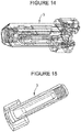
- a 3D CAD example of a passive syringe component/device is shown in Figure 14 .
- a physical picture of the passive syringe safety component/device is shown in Figure 15 .
- Inventive plunger rod 1 may have shaft 5 and finger actuated head portion 7, as shown Figure 2 .
- the distal end 9 of shaft 5 is sized and dimensioned to engage a rubber piston within the syringe to push the piston in the distal direction to expel the medication out of the syringe.
- user actuatable portion 7 of inventive plunger rod 1 has a sensor holder 11, described in detail below, positioned on top of shaft 5 and the wireless sensor generally comprises a wireless transmission chip and contact switch assembly 13, one or more electrically conductive strip(s) 15 and an antenna holder 17 with an antenna, described below.
- Conductive strip 15 has a conductive metallic foil with an electrically conductive adhesive coated on one side of the foil.
- Assembly 13, conductive strip(s) 15 and antenna holder 17 with antenna wire make up the sensor, and a cover 19, which is preferably flexible and more preferably elastomeric, encloses the sensor within sensor holder 11.
- An assembled user actuatable portion 7 is shown in Figure 3B .
- Antenna holder 17, illustrated with both top and bottom perspective views in Figure 4 has antenna wire loop holders 21, which comprise two semi-circular shapes defining a wiring channel 23 therebetween.
- Antenna holder 17 also has two wiring through holes 25 for the antenna wires to pass through holder 17.
- Antenna holder 17 further comprises at least one orientation guide or notch 27 to guide the orientation of antenna holder 17 within sensor holder 11.
- a coil of antenna wire 29 is wrapped around wire loop holders 21.
- the two ends 31 and 33 of the antenna wire are positioned within wiring channels 23 and threaded through holes 25, and are taped to the bottom surface of antenna holder 17 by the electrically conductive adhesive side of strips 15. Hence, strips 15 on the bottom of antenna holder 17 are electrically connected to the antenna wires wounded on top of antenna holder 17.
- Wireless transmission chip and contact switch assembly 13 is best shown in Figure 7 .
- This assembly comprises a wireless transmission chip 35 and one or more contact switches 37 being attached to chip 35 by conductive, double-sided adhesive strips 39.
- Sensor housing 11 contains a number of features or physical features to hold the subunits of the sensor, so that these subunits are separated in the pre-activation configuration.
- Sensor housing 11 has slot or holder 41 sized and dimensioned to receive and hold wireless transmission chip and contact switch assembly 13 on its bottom surface 42, and at least one orientation guide 43 that corresponds to orientation lock or notch 27 on the antenna holder 17.
- Orientation guide 43 fits into orientation notch 27 to ensure that conductive strips 15 located on the bottom surface of antenna guide 17 are positioned directly above contact switches 37.
- Sensor housing 11 also has two supporting surfaces 45 and 47. As best shown in Figure 9 , these two surfaces are formed on an upstanding vertical member; however, this upstanding vertical member may also be formed integrally with the body of sensor housing 11. Supporting surface 45 is located near the top of sensor housing 11, and is adapted to support the outer edge of cover 19. As supported, cover 19 may preferably flex inward when a user pushes plunger rod 1 downward to expel the medication from syringe 3. Cover 19 may be attached to supporting surface 45 by adhesives, spot bonding, ultrasonic welding or other known attachment methods.
- Supporting surface 47 is designed to support antenna holder 17 in the pre-activation configuration.
- Supporting surface 47 is preferably formed by a ledge 49, which is supported in a cantilever fashion from a side of sensor housing 11, as best shown in Figure 9 .
- Ledge 49 supports antenna holder 17 and is designed to flex downward as plunger rod 1 is pushed by the user.
- Ledge 49 separates antenna holder 17 away from wireless transmission chip and contact switch assembly 13, so that the sensor is not assembled and not operational in the pre-activation configuration.
- Ledge 49 provides the physical barrier keeping the subunits of the sensor separated in the pre-activation configuration, as discussed above.
- ledge 49 flexes back to return to its original position. In its original position in the post-activation configuration, ledge 49 retains antenna holder 17 in contact with wireless transmission chip and contact switch assembly 13, and preferably ledge 49 due to its flexibility and cantilever connection applies a force keeping antenna holder 17 in contact with wireless transmission chip and contact switch assembly 13.
- Figure 12 shows plunger rod 1 in the post-activation configuration with the contact switch 37 in assembly 13 being in contact with conductive strip 15 on the bottom of antenna holder 17. As discussed above, conductive strips 15 are electrically connected to the antenna wire 29 wounded on top of antenna holder 17.
- the force necessary to overcome the physical barrier or ledge 49 can be designed to be any force level depending on the geometry and how far physical barrier 49 protrudes from the side of sensor housing 11.
- physical barrier 49 can be a relatively short and thin physical barrier that will require relatively little force to overcome.
- triangular geometry in the drawings it is sticking out straight
- thickness in the drawings it is sticking out straight
- length in the physical barrier 49 which will require significantly more force to overcome.
- antenna holder 17 can pass the physical barrier toward the beginning, somewhere in the middle, or toward the end of the movement of the plunger.
- a low barrier force will mean antenna holder 17 will overcome barrier 49 at the beginning of the movement of plunger 5 during the injection, and a higher barrier force will result in antenna holder 17 to overcome barrier 49 toward the end of the injection.
- Barrier force somewhere in the middle will result in antenna holder 17 overcoming barrier 49 somewhere during the middle of the injection.
- the amount of barrier force depends on several factors including material of construct, geometry, thickness, and length/depth that the barrier extends out from the side wall.
- One of ordinary skill in the art may select a proper level of force to overcome the physical barrier from the disclosure of the present invention.
Landscapes
- Health & Medical Sciences (AREA)
- Life Sciences & Earth Sciences (AREA)
- Engineering & Computer Science (AREA)
- General Health & Medical Sciences (AREA)
- Public Health (AREA)
- Biomedical Technology (AREA)
- Heart & Thoracic Surgery (AREA)
- Veterinary Medicine (AREA)
- Animal Behavior & Ethology (AREA)
- Anesthesiology (AREA)
- Hematology (AREA)
- Vascular Medicine (AREA)
- Medical Informatics (AREA)
- Physics & Mathematics (AREA)
- Medicinal Chemistry (AREA)
- Chemical & Material Sciences (AREA)
- Primary Health Care (AREA)
- Bioinformatics & Cheminformatics (AREA)
- Epidemiology (AREA)
- Biophysics (AREA)
- Pathology (AREA)
- Molecular Biology (AREA)
- Surgery (AREA)
- Infusion, Injection, And Reservoir Apparatuses (AREA)
- Catching Or Destruction (AREA)
- Measurement Of The Respiration, Hearing Ability, Form, And Blood Characteristics Of Living Organisms (AREA)
Description
- The present invention relates generally to a sensor and communication system that can be integrated within a syringe plunger rod to confirm syringe injection and to transmit such information wirelessly.
- In ensuring optimal patient treatment, it is essential for patients to comply with the medication regiments prescribed by their health care provider (HCP). Similarly, because no two patients are identical, to ensure the best care and medication prescribed for the patient, the HCPs need to know that the patient is in compliance with taking his/her prescribed medication. This information will help HCPs to determine if the medication is working for the patient or a better alternative medication regiment may be benefit the patient more.
- Similarly, knowing that patients complied with prescriptions is necessary to determine the efficacy of new medications in clinical trials. In clinical trials, prefilled syringes are commonly used, and often a new drug will be introduced into the market in prefilled syringes first to be followed by more complex delivery devices such as autoinjectors, etc.
- Currently, there are no sensor or electronic system embedded with prefilled syringes or accessorized prefilled syringes that can provide the HCPs with confirmation of syringe injection usage, which can then be used to correlate medication compliance with treatment efficacy. Today, the HCPs rely on the patients to report medication compliance and on their truthfulness outside of the clinical setting. This reliance on patient truthfulness in taking the prescribed medication regiment can be a significant risk in clinical trials, where the investigative new drug's efficacy, benefits and other results depend heavily on the patients' compliance with the prescribed medication regiment.
- Prior art utilizes physical and electronics journals to keep track of patient medication regiment. In addition, other prior art consist of electronic reminders to remind patients to take their medication. Both of these systems are passive and depended on patient truthfulness and compliance, and are only marginally effective. A HCP will not be able to tell if, for example, a patient simply fill in their journals right before going in to see their HCP to show compliance, when the patient had not been compliant. Similarly, with the electronic reminders the patient may simply indicate injection to silence the alarms without actually injecting the medication.
- As such, there exists a need for a means and apparatus to capture actual syringe usage and other confirmation information and to transmit such information for example wirelessly to ensure patient compliance and allow the HCPs to determine the efficacy of the medication.
-
US 2016/015903 A1 relates to a sensor assembly comprising a first and second rotary sensor part which indicate a relative rotational position. The second part is a switch projection being axially moveable relative to the first to contact a sensor area. - Hence, the present invention is directed to methods, designs, and apparatuses for detecting syringe injection and transmitting the injection confirmation information wirelessly to an external receiver. The invention employs the separation of the one or more subunits or subsystems within a wireless transmission system, whereby the subunits are embedded within the syringe plunger rod and kept separate prior to use. When the syringe is injected/used by the user depressing the plunger rod, the separated wireless transmission subunits are brought together and electrically reconnected establishing an operating wireless transmission system.
- The separation of the wireless transmission subsystems, such as the antenna and the wireless transmission chip subsystems, also creates a sensor that detects whether the syringe was injected into the patient. For example, when the antenna and transmission chip subsystems are connected, the sensor is operable after plunger rod has been depressed to confirm syringe injection. At the same time, the sensor transmits the injection confirmation signal to a receiver.
- Thus, the wireless transmission system can be that of a Bluetooth chip and Bluetooth antenna or any other wireless transmission system, whereby the antenna and the integrated and/or transmission chip(s) can be separated to create a confirmation sensor setup.
- To ensure that the antenna and the transmission chip are kept separated and would not unintentionally come together prior to a successful injection, the transmission chip and antenna subsystems are kept separated by a physical barrier that is overcome during injection. During injection, when the plunger rod is depressed by the user, the antenna for example overcomes the physical barrier and comes into contact with the transmission chip to form a complete and operable wireless transmission system which captures and/or transmits the injection confirmation data.
- This subject invention can be integrated within any plunger and utilized for all syringes including but not limited to prefilled syringes intended to be injected using a plunger rod, including but not limited to autoinjectors. The subject invention creates a digital connectivity plunger rod for injection syringes.
- In the accompanying drawings, which form a part of the specification and are to be read in conjunction therewith and in which like reference numerals are used to indicate like parts in the various views:
-
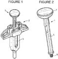
Figure 1 is a perspective view of a prefilled syringe comprising of a passive safety device, a syringe, and an inventive digitally connected plunger rod; -
Figure 2 is a perspective view of an assembled digital connectivity plunge rod fromFigure 1 ; -
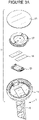
Figure 3A is an exploded view of the digital connectivity plunger rod fromFigure 2 with the antenna wire omitted for clarity;Figure 3B is a top, cross-sectional perspective view of the top of the plunger rod fromFigure 3A showing the antenna holder being retained within the plunger rod by the elastomeric cover; -
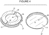
Figure 4 includes a top and a bottom perspective views of an antenna holder and its components with the antenna wire omitted for clarity; -
Figure 5 is an image of the bottom side of the antenna holder showing the ends of the antenna wire being attached to the conductive strips; -
Figure 6 is an image of the top side the antenna holder showing the antenna wire being wrapped around the antenna holder with the free ends of the antenna wire being unattached; -
Figure 7 includes an assembled and an exploded view of the transmission chip system; -
Figure 8 is a partial top perspective view of the plunger rod without the sensor components and cover for clarity; -
Figure 9 is a cross-sectional view of the plunger rod fromFigure 7 ; -
Figure 10 is a partial, cross-sectional view of the top of the plunger rod showing the antenna holder being placed on top of a barrier in the pre-activation configuration; -
Figure 11 is a partial, cross-sectional view of the top of the plunger rod similar to that inFigure 1 in a post-activation configuration; -
Figure 12 is a bottom, cross-sectional perspective view of the plunger rod fromFigure 12 ; -
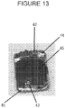
Figure 13 is an image of an alternative embodiment of the present invention where the contact switches are soldered instead of attachment with conductive adhesive onto the wireless transmission chip; -
Figure 14 is a 3D CAD example of a passive syringe component/device; andFigure 15 is a picture of a physical passive syringe safety component/device. - As discussed above, the present invention includes separating a wireless sensor into two or more subunits or parts and keeping the subunits separated within an inventive digitally connected plunger rod in the pre-activation configuration. When its subunits are separated the wireless sensor is preferably non-operational and cannot transmit signals. More preferably, the sensor's subunits are physically separated by a physical barrier that can be overcome with a sufficient force, preferably substantially similar to a force necessary to depress the plunger rod to expel all the medication from the syringe.
- During activation, a user presses the plunger rod thereby applying this force on a top of the plunger rod. This force overcomes the physical barrier separating the subunits and assembles or connects the subunits to complete the sensor, allowing the sensor to be operational and sending a signal to a receiver that the injection is completed. In the post-activation configuration, i.e., when all the medication is expelled from the syringe, preferably the physical barrier can resume its original configuration and applies a pressing force keeping the subunits in contact with each other.
- In one embodiment, the subunits of the sensor may comprise an antenna/antenna holder and a transmission chip and contact switch assembly. In another embodiment, the contact switches can be grouped with the antenna/antenna holder with the power source separated as in the case of Bluetooth Systems Other embodiment may include isolated or separating out any component or subsystem that comprise the communication system.
- Referring to
Figure 1 , an exemplary, inventive digitally connected plunger rod 1 is shown as a part of a syringe unit with a passivesyringe safety component 2, and asyringe 3, preferably a pre-filied syringe, with a sheath on its distal end covering a needle. A 3D CAD example of a passive syringe component/device is shown inFigure 14 . A physical picture of the passive syringe safety component/device is shown inFigure 15 . Inventive plunger rod 1 may haveshaft 5 and finger actuatedhead portion 7, as shownFigure 2 . The distal end 9 ofshaft 5 is sized and dimensioned to engage a rubber piston within the syringe to push the piston in the distal direction to expel the medication out of the syringe. - As shown in
Figure 3A , useractuatable portion 7 of inventive plunger rod 1 has asensor holder 11, described in detail below, positioned on top ofshaft 5 and the wireless sensor generally comprises a wireless transmission chip andcontact switch assembly 13, one or more electrically conductive strip(s) 15 and anantenna holder 17 with an antenna, described below.Conductive strip 15 has a conductive metallic foil with an electrically conductive adhesive coated on one side of the foil.Assembly 13, conductive strip(s) 15 andantenna holder 17 with antenna wire make up the sensor, and acover 19, which is preferably flexible and more preferably elastomeric, encloses the sensor withinsensor holder 11. An assembled useractuatable portion 7 is shown inFigure 3B . -
Antenna holder 17, illustrated with both top and bottom perspective views inFigure 4 , has antennawire loop holders 21, which comprise two semi-circular shapes defining awiring channel 23 therebetween.Antenna holder 17 also has two wiring throughholes 25 for the antenna wires to pass throughholder 17.Antenna holder 17 further comprises at least one orientation guide or notch 27 to guide the orientation ofantenna holder 17 withinsensor holder 11. - As best shown in
Figures 5 and 6 , a coil ofantenna wire 29 is wrapped aroundwire loop holders 21. The two ends 31 and 33 of the antenna wire are positioned withinwiring channels 23 and threaded throughholes 25, and are taped to the bottom surface ofantenna holder 17 by the electrically conductive adhesive side ofstrips 15. Hence, strips 15 on the bottom ofantenna holder 17 are electrically connected to the antenna wires wounded on top ofantenna holder 17. - Wireless transmission chip and
contact switch assembly 13 is best shown inFigure 7 . This assembly comprises awireless transmission chip 35 and one or more contact switches 37 being attached to chip 35 by conductive, double-sided adhesive strips 39. -
Sensor housing 11, as best shown inFigures 8 and 9 , contains a number of features or physical features to hold the subunits of the sensor, so that these subunits are separated in the pre-activation configuration.Sensor housing 11 has slot orholder 41 sized and dimensioned to receive and hold wireless transmission chip andcontact switch assembly 13 on itsbottom surface 42, and at least oneorientation guide 43 that corresponds to orientation lock or notch 27 on theantenna holder 17.Orientation guide 43 fits intoorientation notch 27 to ensure thatconductive strips 15 located on the bottom surface ofantenna guide 17 are positioned directly above contact switches 37. -
Sensor housing 11 also has two supportingsurfaces Figure 9 , these two surfaces are formed on an upstanding vertical member; however, this upstanding vertical member may also be formed integrally with the body ofsensor housing 11. Supportingsurface 45 is located near the top ofsensor housing 11, and is adapted to support the outer edge ofcover 19. As supported, cover 19 may preferably flex inward when a user pushes plunger rod 1 downward to expel the medication fromsyringe 3.Cover 19 may be attached to supportingsurface 45 by adhesives, spot bonding, ultrasonic welding or other known attachment methods. - Supporting
surface 47 is designed to supportantenna holder 17 in the pre-activation configuration. Supportingsurface 47 is preferably formed by aledge 49, which is supported in a cantilever fashion from a side ofsensor housing 11, as best shown inFigure 9 .Ledge 49 supportsantenna holder 17 and is designed to flex downward as plunger rod 1 is pushed by the user.Ledge 49 separatesantenna holder 17 away from wireless transmission chip andcontact switch assembly 13, so that the sensor is not assembled and not operational in the pre-activation configuration.Ledge 49 provides the physical barrier keeping the subunits of the sensor separated in the pre-activation configuration, as discussed above. - When the user applies a force on the top of plunger rod 1 to eject medication from
syringe 3, the same force is applied onhead portion 7. This force pushesantenna holder 17 viacover 17, and overcomesledge 49 and pushesledge 49 downward allowingantenna holder 17 with antenna wiring to pass therethrough to come into contact with wireless transmission chip andcontact switch assembly 13. Contact switches 37 would make electrical contact withconductive strips 15 and the antenna wires. The sequence from pre-activation configuration to post-activation configuration is shown inFigures 10-11 . In this post-activation configuration, the sensor is assembled and the transmission chip is programmed to send a wireless signal through the antenna inantenna holder 17 to a receiver that the injection of the medication is completed. Preferably,ledge 49 flexes back to return to its original position. In its original position in the post-activation configuration,ledge 49 retainsantenna holder 17 in contact with wireless transmission chip andcontact switch assembly 13, and preferablyledge 49 due to its flexibility and cantilever connection applies a force keepingantenna holder 17 in contact with wireless transmission chip andcontact switch assembly 13.Figure 12 shows plunger rod 1 in the post-activation configuration with thecontact switch 37 inassembly 13 being in contact withconductive strip 15 on the bottom ofantenna holder 17. As discussed above,conductive strips 15 are electrically connected to theantenna wire 29 wounded on top ofantenna holder 17. - Preferably, the force necessary to overcome the physical barrier or
ledge 49 can be designed to be any force level depending on the geometry and how farphysical barrier 49 protrudes from the side ofsensor housing 11. In other wordsphysical barrier 49 can be a relatively short and thin physical barrier that will require relatively little force to overcome. Conversely, one may add triangular geometry (in the drawings it is sticking out straight), thickness, and length to thephysical barrier 49 which will require significantly more force to overcome. - Depending on the force to overcome
physical barrier 49,antenna holder 17 can pass the physical barrier toward the beginning, somewhere in the middle, or toward the end of the movement of the plunger. Typically, a low barrier force will meanantenna holder 17 will overcomebarrier 49 at the beginning of the movement ofplunger 5 during the injection, and a higher barrier force will result inantenna holder 17 to overcomebarrier 49 toward the end of the injection. Barrier force somewhere in the middle will result inantenna holder 17 overcomingbarrier 49 somewhere during the middle of the injection. The amount of barrier force depends on several factors including material of construct, geometry, thickness, and length/depth that the barrier extends out from the side wall. One of ordinary skill in the art may select a proper level of force to overcome the physical barrier from the disclosure of the present invention. - While it is apparent that the illustrative embodiments of the invention disclosed herein fulfill the objectives stated above, it is appreciated that numerous modifications and other embodiments may be devised by those skilled in the art. One such modification is that the
contact switch 37 inassembly 13 is soldered towireless transmission chip 35, instead of usingadhesive strips 39, as shown inFigure 13 .
Claims (13)
- A plunger rod (1) adapted to push a medication out of a syringe (3) comprising a shaft (5) sized and dimensioned to act on a piston on the syringe (3) and a finger actuated head portion (7) comprising at least two subunits of a wireless sensor,wherein in a pre-activation configuration the at least two subunits are spaced apart from each other by a physical barrier (49) and the wireless sensor is non-operational,wherein in a post-activation configuration the at least two subunits are connected to each other and the sensor is operational to send a signal,wherein a user activates the finger actuated head portion (7) to move the physical barrier (49) and moves the plunger rod (1) from the pre-activation configuration to the post-activation configuration, wherein the at least two subunits of the sensor comprises an antenna subunit and a wireless transmission subunit.
- The plunger rod (1) of claim 1, wherein the physical barrier (49) if flexible and reverts back to its original configuration after being moved.
- The plunger rod (1) of claim 2, wherein the physical barrier (49) comprises a cantilevered ledge.
- The plunger rod (1) of claim 1, wherein the antenna subunit comprises an antenna wire (29) wrapped around an antenna holder (17) with at least one electrical lead positioned at the bottom of the antenna holder (17).
- The plunger rod (1) of claim 4, wherein the wireless transmission subunit comprises a wireless transmission chip (35) and at least one contact switch (37).
- The plunger rod (1) of claim 5, wherein the at least one contact switch (37) contacts the at least one electrical lead in the post-activation configuration.
- The plunger rod of claim 1, wherein the finger actuated head portion (7) comprises a sensor housing (11).
- The plunger rod (1) of claim 7, wherein the sensor housing (11) defines a slot sized and dimensioned to receive the wireless transmission subunit.
- The plunger rod (1) of claim 8, wherein the sensor housing (11) further comprises an orientation lock sized and dimensioned to match with an orientation notch (27) on the antenna unit.
- The plunger rod (1) of claim 1 further comprising a flexible cover (19) located on top of the finger actuated head portion (7).
- The plunger rod (1) of claim 10, wherein the flexible cover (19) is elastomeric.
- The plunger rod (1) of claim 1, wherein the signal comprises information relating to pushing the medication out of the syringe (3).
- The plunger rod (1) of claim 1, wherein the signal is received by a remote receiver.
Applications Claiming Priority (2)
| Application Number | Priority Date | Filing Date | Title |
|---|---|---|---|
| US201662434131P | 2016-12-14 | 2016-12-14 | |
| PCT/US2017/065965 WO2018111969A1 (en) | 2016-12-14 | 2017-12-13 | Embedded multiple-part sensor within a plunger rod to capture and transmit injection information |
Publications (3)
| Publication Number | Publication Date |
|---|---|
| EP3554587A1 EP3554587A1 (en) | 2019-10-23 |
| EP3554587A4 EP3554587A4 (en) | 2020-07-22 |
| EP3554587B1 true EP3554587B1 (en) | 2022-03-30 |
Family
ID=62559213
Family Applications (1)
| Application Number | Title | Priority Date | Filing Date |
|---|---|---|---|
| EP17880805.1A Active EP3554587B1 (en) | 2016-12-14 | 2017-12-13 | Embedded multiple-part sensor within a plunger rod to capture and transmit injection information |
Country Status (10)
| Country | Link |
|---|---|
| US (1) | US11077254B2 (en) |
| EP (1) | EP3554587B1 (en) |
| JP (1) | JP7071366B2 (en) |
| KR (1) | KR102512203B1 (en) |
| CN (1) | CN110072574B (en) |
| AU (1) | AU2017376239B2 (en) |
| CA (1) | CA3045891A1 (en) |
| ES (1) | ES2917774T3 (en) |
| IL (1) | IL267093B (en) |
| WO (1) | WO2018111969A1 (en) |
Families Citing this family (11)
| Publication number | Priority date | Publication date | Assignee | Title |
|---|---|---|---|---|
| CA3046512A1 (en) | 2016-12-28 | 2018-07-05 | Genentech, Inc. | Injection monitoring device |
| JP2021506972A (en) | 2017-12-15 | 2021-02-22 | プラクシス バイオテック エルエルシー | Inhibitor of fibroblast-activating protein |
| WO2019129618A1 (en) * | 2017-12-28 | 2019-07-04 | Sanofi | A sensor device for attachment to an injection device |
| WO2020132661A2 (en) | 2018-12-21 | 2020-06-25 | Praxis Biotech LLC | Inhibitors of fibroblast activation protein |
| EP4472090A3 (en) | 2020-12-16 | 2025-02-19 | Biocorp Production S.A.S. | Pre-filled syringe with injection end point signalling device |
| EP4392094A1 (en) | 2021-08-24 | 2024-07-03 | Becton Dickinson France | Connected drug delivery device |
| EP4285961A1 (en) | 2022-06-01 | 2023-12-06 | Becton, Dickinson and Company | Drug delivery device with end-of-dose detection |
| EP4285959A1 (en) | 2022-06-01 | 2023-12-06 | Becton, Dickinson and Company | Battery-free sensing solution for drug delivery devices |
| EP4289454A1 (en) | 2022-06-07 | 2023-12-13 | Becton, Dickinson and Company | Reusable digital module for autoinjector |
| EP4445929A1 (en) | 2023-04-14 | 2024-10-16 | Becton, Dickinson and Company | Connected drug delivery device |
| EP4691521A1 (en) | 2024-08-05 | 2026-02-11 | Ypsomed AG | Improved operating assembly for a syringe |
Family Cites Families (28)
| Publication number | Priority date | Publication date | Assignee | Title |
|---|---|---|---|---|
| US4713060A (en) | 1986-06-20 | 1987-12-15 | Becton, Dickinson And Company | Syringe assembly |
| US5704922A (en) | 1996-01-25 | 1998-01-06 | Raya Systems, Inc. | Syringe having electrical contact points for metering doses |
| EP1361908B1 (en) * | 2001-02-14 | 2007-12-19 | Novo Nordisk A/S | Electronically controlled injection or infusion device |
| US7549977B2 (en) * | 2002-12-20 | 2009-06-23 | Medrad, Inc. | Front load pressure jacket system with syringe holder and light illumination |
| US8777889B2 (en) * | 2004-06-15 | 2014-07-15 | Ceramatec, Inc. | Apparatus and method for administering a therapeutic agent into tissue |
| AU2004291040A1 (en) | 2003-11-13 | 2005-06-02 | Alza Corporation | System and method for transdermal delivery |
| US9205193B2 (en) * | 2007-06-12 | 2015-12-08 | Peter V. Boesen | Self-contained medication injection system and method |
| US8894611B2 (en) | 2008-08-29 | 2014-11-25 | Novo Nordisk A/S | Medical injection device with time delay indicator |
| EP2352536B1 (en) * | 2008-11-06 | 2018-03-14 | Novo Nordisk A/S | Electronically assisted drug delivery device |
| US8556865B2 (en) * | 2009-02-27 | 2013-10-15 | Lifescan, Inc. | Medical module for drug delivery pen |
| EP2689359B1 (en) * | 2011-03-24 | 2020-11-25 | Sanofi-Aventis Deutschland GmbH | Device and method for detecting an actuation action performable with a medical device |
| CN102151345B (en) * | 2011-04-25 | 2014-04-16 | 无锡沃骐医疗科技有限公司 | Injector |
| RU2624514C2 (en) * | 2011-09-09 | 2017-07-04 | Мерк Патент Гмбх | Rechargeable automated injector |
| AT512504B1 (en) * | 2012-03-22 | 2013-09-15 | Seibersdorf Labor Gmbh | Apparatus and method for determining the capacity |
| KR101767793B1 (en) * | 2012-10-11 | 2017-08-11 | 케어베이 유럽 리미티드 | Automatic injection training device |
| WO2014064691A2 (en) * | 2012-10-23 | 2014-05-01 | Insuline Medical Ltd. | Drug dispensing-tracking device, system and method |
| EP2958611B1 (en) | 2013-02-19 | 2018-04-11 | Novo Nordisk A/S | Rotary sensor module with axial switch |
| US20150005703A1 (en) | 2013-06-28 | 2015-01-01 | Animas Corporation | Drug infusion device with safety interlock |
| WO2015000091A1 (en) * | 2013-07-03 | 2015-01-08 | Q-Tag Ag | Monitoring product integrity of a pharmaceutical product in a syringe using a miniaturized electronic sensor tag |
| CA2833685A1 (en) * | 2013-11-18 | 2015-05-18 | Duoject Medical Systems Inc. | Auto-injector |
| US20150246179A1 (en) | 2014-03-02 | 2015-09-03 | Nissim Zur | Device and method for drug dosing with administration monitoring, in particular for insulin pen integrated with smart phone apps. |
| US10704944B2 (en) | 2014-09-14 | 2020-07-07 | Becton, Dickinson And Company | System and method for capturing dose information |
| DE102014223693A1 (en) | 2014-11-20 | 2016-05-25 | Vetter Pharma-Fertigung GmbH & Co. KG | drug facility |
| WO2016122974A1 (en) * | 2015-01-26 | 2016-08-04 | Becton, Dickinson And Company | Dose capture device for syringes |
| CN205031665U (en) * | 2015-10-16 | 2016-02-17 | 南昌德漫多科技有限公司 | Injection is carried out and auxiliary device |
| CA3046512A1 (en) * | 2016-12-28 | 2018-07-05 | Genentech, Inc. | Injection monitoring device |
| EP4364768A3 (en) * | 2017-05-19 | 2024-08-07 | Credence Medsystems, Inc. | System and method for collecting injection information |
| US10478561B2 (en) * | 2017-08-03 | 2019-11-19 | Minhong Yu | Wireless transmission system with integrated sensing capability |
-
2017
- 2017-12-13 KR KR1020197019082A patent/KR102512203B1/en active Active
- 2017-12-13 JP JP2019531399A patent/JP7071366B2/en active Active
- 2017-12-13 US US16/469,211 patent/US11077254B2/en active Active
- 2017-12-13 WO PCT/US2017/065965 patent/WO2018111969A1/en not_active Ceased
- 2017-12-13 AU AU2017376239A patent/AU2017376239B2/en active Active
- 2017-12-13 ES ES17880805T patent/ES2917774T3/en active Active
- 2017-12-13 EP EP17880805.1A patent/EP3554587B1/en active Active
- 2017-12-13 CA CA3045891A patent/CA3045891A1/en active Pending
- 2017-12-13 CN CN201780076865.8A patent/CN110072574B/en active Active
- 2017-12-13 IL IL267093A patent/IL267093B/en unknown
Also Published As
| Publication number | Publication date |
|---|---|
| WO2018111969A1 (en) | 2018-06-21 |
| US20190344019A1 (en) | 2019-11-14 |
| KR20190095319A (en) | 2019-08-14 |
| KR102512203B1 (en) | 2023-03-20 |
| CN110072574B (en) | 2022-10-18 |
| CA3045891A1 (en) | 2018-06-21 |
| AU2017376239B2 (en) | 2023-07-06 |
| JP7071366B2 (en) | 2022-05-18 |
| AU2017376239A1 (en) | 2019-07-25 |
| EP3554587A4 (en) | 2020-07-22 |
| BR112019011267A2 (en) | 2019-10-08 |
| IL267093A (en) | 2019-08-29 |
| IL267093B (en) | 2022-08-01 |
| JP2020501667A (en) | 2020-01-23 |
| US11077254B2 (en) | 2021-08-03 |
| CN110072574A (en) | 2019-07-30 |
| EP3554587A1 (en) | 2019-10-23 |
| ES2917774T3 (en) | 2022-07-11 |
Similar Documents
| Publication | Publication Date | Title |
|---|---|---|
| EP3554587B1 (en) | Embedded multiple-part sensor within a plunger rod to capture and transmit injection information | |
| US12280243B2 (en) | Communication device for transmitting information from a medicament delivery device | |
| EP3386566B1 (en) | Communication device for transmitting information from a medicament delivery device | |
| KR101931459B1 (en) | Medicament delivery device | |
| EP3598942B1 (en) | Elastic physiological patch | |
| KR102077410B1 (en) | Drug delivery devices | |
| JP2009530880A (en) | Secure pairing of electronic devices using complex communication means | |
| JP2017500907A (en) | Injection device configured to work with mobile devices | |
| JP2009529930A (en) | Medical system with bi-purpose communication means | |
| CN101405044A (en) | Determination of position of injection needle | |
| HK40016434B (en) | Embedded multiple-part sensor within a plunger rod to capture and transmit injection information | |
| CN110612135A (en) | Flexible electronic label device | |
| EP3471801B1 (en) | Supplementary device for a medicament delivery device | |
| CN101304784A (en) | Applicator cartridge for an electrokinetic delivery system for self-administration | |
| JP7162055B2 (en) | Chemical-solution administration device and control method for chemical-solution administration device | |
| KR20240127100A (en) | Drug injection device | |
| JP7361102B2 (en) | Liquid drug administration device and liquid drug administration set | |
| CN110573200A (en) | Drug delivery device with acoustic transducer | |
| BR112019011267B1 (en) | MULTI-PARTY SENSOR EMBEDDED WITHIN A PLUS ROD TO CAPTURE AND TRANSMIT INJECTION INFORMATION | |
| JP2019063252A (en) | Syringe pump | |
| WO2024137783A1 (en) | Containment, activation, deployment, and integrated functions of flexible, slender elements | |
| MX2008006977A (en) | An applicator cartridge for an electrokinetic delivery system for self administration of medicaments |
Legal Events
| Date | Code | Title | Description |
|---|---|---|---|
| STAA | Information on the status of an ep patent application or granted ep patent |
Free format text: STATUS: THE INTERNATIONAL PUBLICATION HAS BEEN MADE |
|
| PUAI | Public reference made under article 153(3) epc to a published international application that has entered the european phase |
Free format text: ORIGINAL CODE: 0009012 |
|
| STAA | Information on the status of an ep patent application or granted ep patent |
Free format text: STATUS: REQUEST FOR EXAMINATION WAS MADE |
|
| 17P | Request for examination filed |
Effective date: 20190715 |
|
| AK | Designated contracting states |
Kind code of ref document: A1 Designated state(s): AL AT BE BG CH CY CZ DE DK EE ES FI FR GB GR HR HU IE IS IT LI LT LU LV MC MK MT NL NO PL PT RO RS SE SI SK SM TR |
|
| AX | Request for extension of the european patent |
Extension state: BA ME |
|
| DAV | Request for validation of the european patent (deleted) | ||
| DAX | Request for extension of the european patent (deleted) | ||
| TPAC | Observations filed by third parties |
Free format text: ORIGINAL CODE: EPIDOSNTIPA |
|
| A4 | Supplementary search report drawn up and despatched |
Effective date: 20200623 |
|
| RIC1 | Information provided on ipc code assigned before grant |
Ipc: A61M 5/315 20060101AFI20200617BHEP Ipc: A61M 5/50 20060101ALI20200617BHEP |
|
| REG | Reference to a national code |
Ref country code: HK Ref legal event code: DE Ref document number: 40016434 Country of ref document: HK |
|
| GRAP | Despatch of communication of intention to grant a patent |
Free format text: ORIGINAL CODE: EPIDOSNIGR1 |
|
| STAA | Information on the status of an ep patent application or granted ep patent |
Free format text: STATUS: GRANT OF PATENT IS INTENDED |
|
| INTG | Intention to grant announced |
Effective date: 20211125 |
|
| GRAS | Grant fee paid |
Free format text: ORIGINAL CODE: EPIDOSNIGR3 |
|
| GRAA | (expected) grant |
Free format text: ORIGINAL CODE: 0009210 |
|
| STAA | Information on the status of an ep patent application or granted ep patent |
Free format text: STATUS: THE PATENT HAS BEEN GRANTED |
|
| AK | Designated contracting states |
Kind code of ref document: B1 Designated state(s): AL AT BE BG CH CY CZ DE DK EE ES FI FR GB GR HR HU IE IS IT LI LT LU LV MC MK MT NL NO PL PT RO RS SE SI SK SM TR |
|
| REG | Reference to a national code |
Ref country code: GB Ref legal event code: FG4D |
|
| REG | Reference to a national code |
Ref country code: CH Ref legal event code: EP |
|
| REG | Reference to a national code |
Ref country code: AT Ref legal event code: REF Ref document number: 1478586 Country of ref document: AT Kind code of ref document: T Effective date: 20220415 |
|
| REG | Reference to a national code |
Ref country code: DE Ref legal event code: R096 Ref document number: 602017055369 Country of ref document: DE |
|
| REG | Reference to a national code |
Ref country code: IE Ref legal event code: FG4D |
|
| REG | Reference to a national code |
Ref country code: NL Ref legal event code: FP |
|
| REG | Reference to a national code |
Ref country code: SE Ref legal event code: TRGR |
|
| REG | Reference to a national code |
Ref country code: LT Ref legal event code: MG9D Ref country code: ES Ref legal event code: FG2A Ref document number: 2917774 Country of ref document: ES Kind code of ref document: T3 Effective date: 20220711 |
|
| PG25 | Lapsed in a contracting state [announced via postgrant information from national office to epo] |
Ref country code: RS Free format text: LAPSE BECAUSE OF FAILURE TO SUBMIT A TRANSLATION OF THE DESCRIPTION OR TO PAY THE FEE WITHIN THE PRESCRIBED TIME-LIMIT Effective date: 20220330 Ref country code: NO Free format text: LAPSE BECAUSE OF FAILURE TO SUBMIT A TRANSLATION OF THE DESCRIPTION OR TO PAY THE FEE WITHIN THE PRESCRIBED TIME-LIMIT Effective date: 20220630 Ref country code: LT Free format text: LAPSE BECAUSE OF FAILURE TO SUBMIT A TRANSLATION OF THE DESCRIPTION OR TO PAY THE FEE WITHIN THE PRESCRIBED TIME-LIMIT Effective date: 20220330 Ref country code: HR Free format text: LAPSE BECAUSE OF FAILURE TO SUBMIT A TRANSLATION OF THE DESCRIPTION OR TO PAY THE FEE WITHIN THE PRESCRIBED TIME-LIMIT Effective date: 20220330 Ref country code: BG Free format text: LAPSE BECAUSE OF FAILURE TO SUBMIT A TRANSLATION OF THE DESCRIPTION OR TO PAY THE FEE WITHIN THE PRESCRIBED TIME-LIMIT Effective date: 20220630 |
|
| REG | Reference to a national code |
Ref country code: AT Ref legal event code: MK05 Ref document number: 1478586 Country of ref document: AT Kind code of ref document: T Effective date: 20220330 |
|
| PG25 | Lapsed in a contracting state [announced via postgrant information from national office to epo] |
Ref country code: LV Free format text: LAPSE BECAUSE OF FAILURE TO SUBMIT A TRANSLATION OF THE DESCRIPTION OR TO PAY THE FEE WITHIN THE PRESCRIBED TIME-LIMIT Effective date: 20220330 Ref country code: GR Free format text: LAPSE BECAUSE OF FAILURE TO SUBMIT A TRANSLATION OF THE DESCRIPTION OR TO PAY THE FEE WITHIN THE PRESCRIBED TIME-LIMIT Effective date: 20220701 Ref country code: FI Free format text: LAPSE BECAUSE OF FAILURE TO SUBMIT A TRANSLATION OF THE DESCRIPTION OR TO PAY THE FEE WITHIN THE PRESCRIBED TIME-LIMIT Effective date: 20220330 |
|
| PG25 | Lapsed in a contracting state [announced via postgrant information from national office to epo] |
Ref country code: SM Free format text: LAPSE BECAUSE OF FAILURE TO SUBMIT A TRANSLATION OF THE DESCRIPTION OR TO PAY THE FEE WITHIN THE PRESCRIBED TIME-LIMIT Effective date: 20220330 Ref country code: SK Free format text: LAPSE BECAUSE OF FAILURE TO SUBMIT A TRANSLATION OF THE DESCRIPTION OR TO PAY THE FEE WITHIN THE PRESCRIBED TIME-LIMIT Effective date: 20220330 Ref country code: RO Free format text: LAPSE BECAUSE OF FAILURE TO SUBMIT A TRANSLATION OF THE DESCRIPTION OR TO PAY THE FEE WITHIN THE PRESCRIBED TIME-LIMIT Effective date: 20220330 Ref country code: PT Free format text: LAPSE BECAUSE OF FAILURE TO SUBMIT A TRANSLATION OF THE DESCRIPTION OR TO PAY THE FEE WITHIN THE PRESCRIBED TIME-LIMIT Effective date: 20220801 Ref country code: EE Free format text: LAPSE BECAUSE OF FAILURE TO SUBMIT A TRANSLATION OF THE DESCRIPTION OR TO PAY THE FEE WITHIN THE PRESCRIBED TIME-LIMIT Effective date: 20220330 Ref country code: CZ Free format text: LAPSE BECAUSE OF FAILURE TO SUBMIT A TRANSLATION OF THE DESCRIPTION OR TO PAY THE FEE WITHIN THE PRESCRIBED TIME-LIMIT Effective date: 20220330 Ref country code: AT Free format text: LAPSE BECAUSE OF FAILURE TO SUBMIT A TRANSLATION OF THE DESCRIPTION OR TO PAY THE FEE WITHIN THE PRESCRIBED TIME-LIMIT Effective date: 20220330 |
|
| PG25 | Lapsed in a contracting state [announced via postgrant information from national office to epo] |
Ref country code: PL Free format text: LAPSE BECAUSE OF FAILURE TO SUBMIT A TRANSLATION OF THE DESCRIPTION OR TO PAY THE FEE WITHIN THE PRESCRIBED TIME-LIMIT Effective date: 20220330 Ref country code: IS Free format text: LAPSE BECAUSE OF FAILURE TO SUBMIT A TRANSLATION OF THE DESCRIPTION OR TO PAY THE FEE WITHIN THE PRESCRIBED TIME-LIMIT Effective date: 20220730 Ref country code: AL Free format text: LAPSE BECAUSE OF FAILURE TO SUBMIT A TRANSLATION OF THE DESCRIPTION OR TO PAY THE FEE WITHIN THE PRESCRIBED TIME-LIMIT Effective date: 20220330 |
|
| REG | Reference to a national code |
Ref country code: DE Ref legal event code: R097 Ref document number: 602017055369 Country of ref document: DE |
|
| PG25 | Lapsed in a contracting state [announced via postgrant information from national office to epo] |
Ref country code: DK Free format text: LAPSE BECAUSE OF FAILURE TO SUBMIT A TRANSLATION OF THE DESCRIPTION OR TO PAY THE FEE WITHIN THE PRESCRIBED TIME-LIMIT Effective date: 20220330 |
|
| PLBE | No opposition filed within time limit |
Free format text: ORIGINAL CODE: 0009261 |
|
| STAA | Information on the status of an ep patent application or granted ep patent |
Free format text: STATUS: NO OPPOSITION FILED WITHIN TIME LIMIT |
|
| 26N | No opposition filed |
Effective date: 20230103 |
|
| PG25 | Lapsed in a contracting state [announced via postgrant information from national office to epo] |
Ref country code: SI Free format text: LAPSE BECAUSE OF FAILURE TO SUBMIT A TRANSLATION OF THE DESCRIPTION OR TO PAY THE FEE WITHIN THE PRESCRIBED TIME-LIMIT Effective date: 20220330 |
|
| P01 | Opt-out of the competence of the unified patent court (upc) registered |
Effective date: 20230329 |
|
| REG | Reference to a national code |
Ref country code: BE Ref legal event code: MM Effective date: 20221231 |
|
| PG25 | Lapsed in a contracting state [announced via postgrant information from national office to epo] |
Ref country code: LU Free format text: LAPSE BECAUSE OF NON-PAYMENT OF DUE FEES Effective date: 20221213 |
|
| PG25 | Lapsed in a contracting state [announced via postgrant information from national office to epo] |
Ref country code: IE Free format text: LAPSE BECAUSE OF NON-PAYMENT OF DUE FEES Effective date: 20221213 |
|
| PG25 | Lapsed in a contracting state [announced via postgrant information from national office to epo] |
Ref country code: BE Free format text: LAPSE BECAUSE OF NON-PAYMENT OF DUE FEES Effective date: 20221231 |
|
| PG25 | Lapsed in a contracting state [announced via postgrant information from national office to epo] |
Ref country code: HU Free format text: LAPSE BECAUSE OF FAILURE TO SUBMIT A TRANSLATION OF THE DESCRIPTION OR TO PAY THE FEE WITHIN THE PRESCRIBED TIME-LIMIT; INVALID AB INITIO Effective date: 20171213 |
|
| PG25 | Lapsed in a contracting state [announced via postgrant information from national office to epo] |
Ref country code: CY Free format text: LAPSE BECAUSE OF FAILURE TO SUBMIT A TRANSLATION OF THE DESCRIPTION OR TO PAY THE FEE WITHIN THE PRESCRIBED TIME-LIMIT Effective date: 20220330 |
|
| PG25 | Lapsed in a contracting state [announced via postgrant information from national office to epo] |
Ref country code: MK Free format text: LAPSE BECAUSE OF FAILURE TO SUBMIT A TRANSLATION OF THE DESCRIPTION OR TO PAY THE FEE WITHIN THE PRESCRIBED TIME-LIMIT Effective date: 20220330 |
|
| PG25 | Lapsed in a contracting state [announced via postgrant information from national office to epo] |
Ref country code: MC Free format text: LAPSE BECAUSE OF FAILURE TO SUBMIT A TRANSLATION OF THE DESCRIPTION OR TO PAY THE FEE WITHIN THE PRESCRIBED TIME-LIMIT Effective date: 20220330 |
|
| PG25 | Lapsed in a contracting state [announced via postgrant information from national office to epo] |
Ref country code: MC Free format text: LAPSE BECAUSE OF FAILURE TO SUBMIT A TRANSLATION OF THE DESCRIPTION OR TO PAY THE FEE WITHIN THE PRESCRIBED TIME-LIMIT Effective date: 20220330 |
|
| PG25 | Lapsed in a contracting state [announced via postgrant information from national office to epo] |
Ref country code: MT Free format text: LAPSE BECAUSE OF FAILURE TO SUBMIT A TRANSLATION OF THE DESCRIPTION OR TO PAY THE FEE WITHIN THE PRESCRIBED TIME-LIMIT Effective date: 20220330 |
|
| PGFP | Annual fee paid to national office [announced via postgrant information from national office to epo] |
Ref country code: ES Payment date: 20250120 Year of fee payment: 8 |
|
| PGFP | Annual fee paid to national office [announced via postgrant information from national office to epo] |
Ref country code: CH Payment date: 20250101 Year of fee payment: 8 |
|
| PGFP | Annual fee paid to national office [announced via postgrant information from national office to epo] |
Ref country code: NL Payment date: 20251119 Year of fee payment: 9 |
|
| REG | Reference to a national code |
Ref country code: CH Ref legal event code: U11 Free format text: ST27 STATUS EVENT CODE: U-0-0-U10-U11 (AS PROVIDED BY THE NATIONAL OFFICE) Effective date: 20260101 |
|
| PGFP | Annual fee paid to national office [announced via postgrant information from national office to epo] |
Ref country code: DE Payment date: 20251126 Year of fee payment: 9 |
|
| PGFP | Annual fee paid to national office [announced via postgrant information from national office to epo] |
Ref country code: GB Payment date: 20251120 Year of fee payment: 9 |
|
| PGFP | Annual fee paid to national office [announced via postgrant information from national office to epo] |
Ref country code: IT Payment date: 20251119 Year of fee payment: 9 |
|
| PGFP | Annual fee paid to national office [announced via postgrant information from national office to epo] |
Ref country code: FR Payment date: 20251120 Year of fee payment: 9 |
|
| PGFP | Annual fee paid to national office [announced via postgrant information from national office to epo] |
Ref country code: TR Payment date: 20251202 Year of fee payment: 9 |
|
| PGFP | Annual fee paid to national office [announced via postgrant information from national office to epo] |
Ref country code: SE Payment date: 20251119 Year of fee payment: 9 |