EP3554587B1 - Eingebetteter mehrteilige sensor in einer kolbenstange zur erfassung und übertragung von injektionsinformationen - Google Patents
Eingebetteter mehrteilige sensor in einer kolbenstange zur erfassung und übertragung von injektionsinformationen Download PDFInfo
- Publication number
- EP3554587B1 EP3554587B1 EP17880805.1A EP17880805A EP3554587B1 EP 3554587 B1 EP3554587 B1 EP 3554587B1 EP 17880805 A EP17880805 A EP 17880805A EP 3554587 B1 EP3554587 B1 EP 3554587B1
- Authority
- EP
- European Patent Office
- Prior art keywords
- plunger rod
- antenna
- sensor
- syringe
- subunits
- Prior art date
- Legal status (The legal status is an assumption and is not a legal conclusion. Google has not performed a legal analysis and makes no representation as to the accuracy of the status listed.)
- Active
Links
Images


Classifications
-
- A—HUMAN NECESSITIES
- A61—MEDICAL OR VETERINARY SCIENCE; HYGIENE
- A61M—DEVICES FOR INTRODUCING MEDIA INTO, OR ONTO, THE BODY; DEVICES FOR TRANSDUCING BODY MEDIA OR FOR TAKING MEDIA FROM THE BODY; DEVICES FOR PRODUCING OR ENDING SLEEP OR STUPOR
- A61M5/00—Devices for bringing media into the body in a subcutaneous, intra-vascular or intramuscular way; Accessories therefor, e.g. filling or cleaning devices, arm-rests
- A61M5/178—Syringes
- A61M5/31—Details
- A61M5/315—Pistons; Piston-rods; Guiding, blocking or restricting the movement of the rod or piston; Appliances on the rod for facilitating dosing ; Dosing mechanisms
-
- A—HUMAN NECESSITIES
- A61—MEDICAL OR VETERINARY SCIENCE; HYGIENE
- A61B—DIAGNOSIS; SURGERY; IDENTIFICATION
- A61B5/00—Measuring for diagnostic purposes; Identification of persons
- A61B5/48—Other medical applications
- A61B5/4833—Assessment of subject's compliance to treatment
-
- A—HUMAN NECESSITIES
- A61—MEDICAL OR VETERINARY SCIENCE; HYGIENE
- A61M—DEVICES FOR INTRODUCING MEDIA INTO, OR ONTO, THE BODY; DEVICES FOR TRANSDUCING BODY MEDIA OR FOR TAKING MEDIA FROM THE BODY; DEVICES FOR PRODUCING OR ENDING SLEEP OR STUPOR
- A61M5/00—Devices for bringing media into the body in a subcutaneous, intra-vascular or intramuscular way; Accessories therefor, e.g. filling or cleaning devices, arm-rests
- A61M5/178—Syringes
- A61M5/31—Details
- A61M5/315—Pistons; Piston-rods; Guiding, blocking or restricting the movement of the rod or piston; Appliances on the rod for facilitating dosing ; Dosing mechanisms
- A61M5/31565—Administration mechanisms, i.e. constructional features, modes of administering a dose
- A61M5/31566—Means improving security or handling thereof
- A61M5/31568—Means keeping track of the total dose administered, e.g. since the cartridge was inserted
-
- A—HUMAN NECESSITIES
- A61—MEDICAL OR VETERINARY SCIENCE; HYGIENE
- A61M—DEVICES FOR INTRODUCING MEDIA INTO, OR ONTO, THE BODY; DEVICES FOR TRANSDUCING BODY MEDIA OR FOR TAKING MEDIA FROM THE BODY; DEVICES FOR PRODUCING OR ENDING SLEEP OR STUPOR
- A61M5/00—Devices for bringing media into the body in a subcutaneous, intra-vascular or intramuscular way; Accessories therefor, e.g. filling or cleaning devices, arm-rests
- A61M5/178—Syringes
- A61M5/31—Details
- A61M5/315—Pistons; Piston-rods; Guiding, blocking or restricting the movement of the rod or piston; Appliances on the rod for facilitating dosing ; Dosing mechanisms
- A61M5/31565—Administration mechanisms, i.e. constructional features, modes of administering a dose
- A61M5/31566—Means improving security or handling thereof
- A61M5/3157—Means providing feedback signals when administration is completed
-
- A—HUMAN NECESSITIES
- A61—MEDICAL OR VETERINARY SCIENCE; HYGIENE
- A61M—DEVICES FOR INTRODUCING MEDIA INTO, OR ONTO, THE BODY; DEVICES FOR TRANSDUCING BODY MEDIA OR FOR TAKING MEDIA FROM THE BODY; DEVICES FOR PRODUCING OR ENDING SLEEP OR STUPOR
- A61M5/00—Devices for bringing media into the body in a subcutaneous, intra-vascular or intramuscular way; Accessories therefor, e.g. filling or cleaning devices, arm-rests
- A61M5/50—Devices for bringing media into the body in a subcutaneous, intra-vascular or intramuscular way; Accessories therefor, e.g. filling or cleaning devices, arm-rests having means for preventing re-use, or for indicating if defective, used, tampered with or unsterile
-
- G—PHYSICS
- G16—INFORMATION AND COMMUNICATION TECHNOLOGY [ICT] SPECIALLY ADAPTED FOR SPECIFIC APPLICATION FIELDS
- G16H—HEALTHCARE INFORMATICS, i.e. INFORMATION AND COMMUNICATION TECHNOLOGY [ICT] SPECIALLY ADAPTED FOR THE HANDLING OR PROCESSING OF MEDICAL OR HEALTHCARE DATA
- G16H20/00—ICT specially adapted for therapies or health-improving plans, e.g. for handling prescriptions, for steering therapy or for monitoring patient compliance
- G16H20/10—ICT specially adapted for therapies or health-improving plans, e.g. for handling prescriptions, for steering therapy or for monitoring patient compliance relating to drugs or medications, e.g. for ensuring correct administration to patients
- G16H20/17—ICT specially adapted for therapies or health-improving plans, e.g. for handling prescriptions, for steering therapy or for monitoring patient compliance relating to drugs or medications, e.g. for ensuring correct administration to patients delivered via infusion or injection
-
- A—HUMAN NECESSITIES
- A61—MEDICAL OR VETERINARY SCIENCE; HYGIENE
- A61M—DEVICES FOR INTRODUCING MEDIA INTO, OR ONTO, THE BODY; DEVICES FOR TRANSDUCING BODY MEDIA OR FOR TAKING MEDIA FROM THE BODY; DEVICES FOR PRODUCING OR ENDING SLEEP OR STUPOR
- A61M2205/00—General characteristics of the apparatus
- A61M2205/02—General characteristics of the apparatus characterised by a particular materials
- A61M2205/0216—Materials providing elastic properties, e.g. for facilitating deformation and avoid breaking
-
- A—HUMAN NECESSITIES
- A61—MEDICAL OR VETERINARY SCIENCE; HYGIENE
- A61M—DEVICES FOR INTRODUCING MEDIA INTO, OR ONTO, THE BODY; DEVICES FOR TRANSDUCING BODY MEDIA OR FOR TAKING MEDIA FROM THE BODY; DEVICES FOR PRODUCING OR ENDING SLEEP OR STUPOR
- A61M2205/00—General characteristics of the apparatus
- A61M2205/33—Controlling, regulating or measuring
- A61M2205/3317—Electromagnetic, inductive or dielectric measuring means
-
- A—HUMAN NECESSITIES
- A61—MEDICAL OR VETERINARY SCIENCE; HYGIENE
- A61M—DEVICES FOR INTRODUCING MEDIA INTO, OR ONTO, THE BODY; DEVICES FOR TRANSDUCING BODY MEDIA OR FOR TAKING MEDIA FROM THE BODY; DEVICES FOR PRODUCING OR ENDING SLEEP OR STUPOR
- A61M2205/00—General characteristics of the apparatus
- A61M2205/35—Communication
- A61M2205/3576—Communication with non implanted data transmission devices, e.g. using external transmitter or receiver
- A61M2205/3584—Communication with non implanted data transmission devices, e.g. using external transmitter or receiver using modem, internet or Bluetooth®
-
- A—HUMAN NECESSITIES
- A61—MEDICAL OR VETERINARY SCIENCE; HYGIENE
- A61M—DEVICES FOR INTRODUCING MEDIA INTO, OR ONTO, THE BODY; DEVICES FOR TRANSDUCING BODY MEDIA OR FOR TAKING MEDIA FROM THE BODY; DEVICES FOR PRODUCING OR ENDING SLEEP OR STUPOR
- A61M2205/00—General characteristics of the apparatus
- A61M2205/35—Communication
- A61M2205/3576—Communication with non implanted data transmission devices, e.g. using external transmitter or receiver
- A61M2205/3592—Communication with non implanted data transmission devices, e.g. using external transmitter or receiver using telemetric means, e.g. radio or optical transmission
-
- A—HUMAN NECESSITIES
- A61—MEDICAL OR VETERINARY SCIENCE; HYGIENE
- A61M—DEVICES FOR INTRODUCING MEDIA INTO, OR ONTO, THE BODY; DEVICES FOR TRANSDUCING BODY MEDIA OR FOR TAKING MEDIA FROM THE BODY; DEVICES FOR PRODUCING OR ENDING SLEEP OR STUPOR
- A61M2205/00—General characteristics of the apparatus
- A61M2205/50—General characteristics of the apparatus with microprocessors or computers
Definitions
- the present invention relates generally to a sensor and communication system that can be integrated within a syringe plunger rod to confirm syringe injection and to transmit such information wirelessly.
- HCP health care provider
- prefilled syringes are commonly used, and often a new drug will be introduced into the market in prefilled syringes first to be followed by more complex delivery devices such as autoinjectors, etc.
- Prior art utilizes physical and electronics journals to keep track of patient medication regiment.
- other prior art consist of electronic reminders to remind patients to take their medication. Both of these systems are passive and depended on patient truthfulness and compliance, and are only marginally effective.
- a HCP will not be able to tell if, for example, a patient simply fill in their journals right before going in to see their HCP to show compliance, when the patient had not been compliant.
- the electronic reminders the patient may simply indicate injection to silence the alarms without actually injecting the medication.
- US 2016/015903 A1 relates to a sensor assembly comprising a first and second rotary sensor part which indicate a relative rotational position.
- the second part is a switch projection being axially moveable relative to the first to contact a sensor area.
- the present invention is directed to methods, designs, and apparatuses for detecting syringe injection and transmitting the injection confirmation information wirelessly to an external receiver.
- the invention employs the separation of the one or more subunits or subsystems within a wireless transmission system, whereby the subunits are embedded within the syringe plunger rod and kept separate prior to use.
- the separated wireless transmission subunits are brought together and electrically reconnected establishing an operating wireless transmission system.
- the separation of the wireless transmission subsystems also creates a sensor that detects whether the syringe was injected into the patient. For example, when the antenna and transmission chip subsystems are connected, the sensor is operable after plunger rod has been depressed to confirm syringe injection. At the same time, the sensor transmits the injection confirmation signal to a receiver.
- the wireless transmission system can be that of a Bluetooth chip and Bluetooth antenna or any other wireless transmission system, whereby the antenna and the integrated and/or transmission chip(s) can be separated to create a confirmation sensor setup.
- the transmission chip and antenna subsystems are kept separated by a physical barrier that is overcome during injection.
- the antenna for example overcomes the physical barrier and comes into contact with the transmission chip to form a complete and operable wireless transmission system which captures and/or transmits the injection confirmation data.
- This subject invention can be integrated within any plunger and utilized for all syringes including but not limited to prefilled syringes intended to be injected using a plunger rod, including but not limited to autoinjectors.
- the subject invention creates a digital connectivity plunger rod for injection syringes.
- the present invention includes separating a wireless sensor into two or more subunits or parts and keeping the subunits separated within an inventive digitally connected plunger rod in the pre-activation configuration.
- the wireless sensor is preferably non-operational and cannot transmit signals.
- the sensor's subunits are physically separated by a physical barrier that can be overcome with a sufficient force, preferably substantially similar to a force necessary to depress the plunger rod to expel all the medication from the syringe.
- a user presses the plunger rod thereby applying this force on a top of the plunger rod.
- This force overcomes the physical barrier separating the subunits and assembles or connects the subunits to complete the sensor, allowing the sensor to be operational and sending a signal to a receiver that the injection is completed.
- the physical barrier can resume its original configuration and applies a pressing force keeping the subunits in contact with each other.
- the subunits of the sensor may comprise an antenna/antenna holder and a transmission chip and contact switch assembly.
- the contact switches can be grouped with the antenna/antenna holder with the power source separated as in the case of Bluetooth Systems
- Other embodiment may include isolated or separating out any component or subsystem that comprise the communication system.
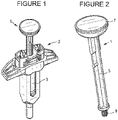
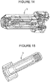
- an exemplary, inventive digitally connected plunger rod 1 is shown as a part of a syringe unit with a passive syringe safety component 2, and a syringe 3, preferably a pre-filied syringe, with a sheath on its distal end covering a needle.
- a 3D CAD example of a passive syringe component/device is shown in Figure 14 .
- a physical picture of the passive syringe safety component/device is shown in Figure 15 .
- Inventive plunger rod 1 may have shaft 5 and finger actuated head portion 7, as shown Figure 2 .
- the distal end 9 of shaft 5 is sized and dimensioned to engage a rubber piston within the syringe to push the piston in the distal direction to expel the medication out of the syringe.
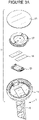
- user actuatable portion 7 of inventive plunger rod 1 has a sensor holder 11, described in detail below, positioned on top of shaft 5 and the wireless sensor generally comprises a wireless transmission chip and contact switch assembly 13, one or more electrically conductive strip(s) 15 and an antenna holder 17 with an antenna, described below.
- Conductive strip 15 has a conductive metallic foil with an electrically conductive adhesive coated on one side of the foil.
- Assembly 13, conductive strip(s) 15 and antenna holder 17 with antenna wire make up the sensor, and a cover 19, which is preferably flexible and more preferably elastomeric, encloses the sensor within sensor holder 11.
- An assembled user actuatable portion 7 is shown in Figure 3B .
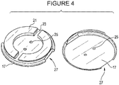
- Antenna holder 17, illustrated with both top and bottom perspective views in Figure 4 has antenna wire loop holders 21, which comprise two semi-circular shapes defining a wiring channel 23 therebetween.
- Antenna holder 17 also has two wiring through holes 25 for the antenna wires to pass through holder 17.
- Antenna holder 17 further comprises at least one orientation guide or notch 27 to guide the orientation of antenna holder 17 within sensor holder 11.
- a coil of antenna wire 29 is wrapped around wire loop holders 21.
- the two ends 31 and 33 of the antenna wire are positioned within wiring channels 23 and threaded through holes 25, and are taped to the bottom surface of antenna holder 17 by the electrically conductive adhesive side of strips 15. Hence, strips 15 on the bottom of antenna holder 17 are electrically connected to the antenna wires wounded on top of antenna holder 17.
- Wireless transmission chip and contact switch assembly 13 is best shown in Figure 7 .
- This assembly comprises a wireless transmission chip 35 and one or more contact switches 37 being attached to chip 35 by conductive, double-sided adhesive strips 39.
- Sensor housing 11 contains a number of features or physical features to hold the subunits of the sensor, so that these subunits are separated in the pre-activation configuration.
- Sensor housing 11 has slot or holder 41 sized and dimensioned to receive and hold wireless transmission chip and contact switch assembly 13 on its bottom surface 42, and at least one orientation guide 43 that corresponds to orientation lock or notch 27 on the antenna holder 17.
- Orientation guide 43 fits into orientation notch 27 to ensure that conductive strips 15 located on the bottom surface of antenna guide 17 are positioned directly above contact switches 37.
- Sensor housing 11 also has two supporting surfaces 45 and 47. As best shown in Figure 9 , these two surfaces are formed on an upstanding vertical member; however, this upstanding vertical member may also be formed integrally with the body of sensor housing 11. Supporting surface 45 is located near the top of sensor housing 11, and is adapted to support the outer edge of cover 19. As supported, cover 19 may preferably flex inward when a user pushes plunger rod 1 downward to expel the medication from syringe 3. Cover 19 may be attached to supporting surface 45 by adhesives, spot bonding, ultrasonic welding or other known attachment methods.
- Supporting surface 47 is designed to support antenna holder 17 in the pre-activation configuration.
- Supporting surface 47 is preferably formed by a ledge 49, which is supported in a cantilever fashion from a side of sensor housing 11, as best shown in Figure 9 .
- Ledge 49 supports antenna holder 17 and is designed to flex downward as plunger rod 1 is pushed by the user.
- Ledge 49 separates antenna holder 17 away from wireless transmission chip and contact switch assembly 13, so that the sensor is not assembled and not operational in the pre-activation configuration.
- Ledge 49 provides the physical barrier keeping the subunits of the sensor separated in the pre-activation configuration, as discussed above.
- ledge 49 flexes back to return to its original position. In its original position in the post-activation configuration, ledge 49 retains antenna holder 17 in contact with wireless transmission chip and contact switch assembly 13, and preferably ledge 49 due to its flexibility and cantilever connection applies a force keeping antenna holder 17 in contact with wireless transmission chip and contact switch assembly 13.
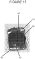
- Figure 12 shows plunger rod 1 in the post-activation configuration with the contact switch 37 in assembly 13 being in contact with conductive strip 15 on the bottom of antenna holder 17. As discussed above, conductive strips 15 are electrically connected to the antenna wire 29 wounded on top of antenna holder 17.
- the force necessary to overcome the physical barrier or ledge 49 can be designed to be any force level depending on the geometry and how far physical barrier 49 protrudes from the side of sensor housing 11.
- physical barrier 49 can be a relatively short and thin physical barrier that will require relatively little force to overcome.
- triangular geometry in the drawings it is sticking out straight
- thickness in the drawings it is sticking out straight
- length in the physical barrier 49 which will require significantly more force to overcome.
- antenna holder 17 can pass the physical barrier toward the beginning, somewhere in the middle, or toward the end of the movement of the plunger.
- a low barrier force will mean antenna holder 17 will overcome barrier 49 at the beginning of the movement of plunger 5 during the injection, and a higher barrier force will result in antenna holder 17 to overcome barrier 49 toward the end of the injection.
- Barrier force somewhere in the middle will result in antenna holder 17 overcoming barrier 49 somewhere during the middle of the injection.
- the amount of barrier force depends on several factors including material of construct, geometry, thickness, and length/depth that the barrier extends out from the side wall.
- One of ordinary skill in the art may select a proper level of force to overcome the physical barrier from the disclosure of the present invention.
Landscapes
- Health & Medical Sciences (AREA)
- Life Sciences & Earth Sciences (AREA)
- Engineering & Computer Science (AREA)
- General Health & Medical Sciences (AREA)
- Public Health (AREA)
- Biomedical Technology (AREA)
- Heart & Thoracic Surgery (AREA)
- Veterinary Medicine (AREA)
- Animal Behavior & Ethology (AREA)
- Anesthesiology (AREA)
- Hematology (AREA)
- Vascular Medicine (AREA)
- Medical Informatics (AREA)
- Physics & Mathematics (AREA)
- Medicinal Chemistry (AREA)
- Chemical & Material Sciences (AREA)
- Primary Health Care (AREA)
- Bioinformatics & Cheminformatics (AREA)
- Epidemiology (AREA)
- Biophysics (AREA)
- Pathology (AREA)
- Molecular Biology (AREA)
- Surgery (AREA)
- Infusion, Injection, And Reservoir Apparatuses (AREA)
- Catching Or Destruction (AREA)
- Measurement Of The Respiration, Hearing Ability, Form, And Blood Characteristics Of Living Organisms (AREA)
Claims (13)
- Stößelstange (1), die dazu ausgeführt ist, eine Medikation aus einer Spritze (3) zu schieben, aufweisend einen Schaft (5), der so bemessen und dimensioniert ist, dass er auf einen Kolben an der Spritze (3) wirkt, und einen fingerbetätigten Kopfabschnitt (7), der zumindest zwei Untereinheiten eines drahtlosen Sensors aufweist,wobei die zumindest zwei Untereinheiten in einer Konfiguration vor der Betätigung durch eine physische Barriere (49) voneinander beabstandet sind und der drahtlose Sensor außer Betrieb ist,wobei die zumindest zwei Untereinheiten in einer Konfiguration nach der Betätigung miteinander verbunden sind und der Sensor zum Senden eines Signals betriebsfähig ist,wobei ein Benutzer den fingerbetätigten Kopfabschnitt (7) betätigt, um die physische Barriere (49) zu bewegen, und die Stößelstange (1) aus der Konfiguration vor der Betätigung in die Konfiguration nach der Betätigung bewegt, wobei die zumindest zwei Untereinheiten des Sensors eine Antennen-Untereinheit und eine drahtlose Sende-Untereinheit aufweisen.
- Stößelstange (1) nach Anspruch 1, wobei die physische Barriere (49) flexibel ist und in ihre ursprüngliche Konfiguration zurückkehrt, nachdem sie bewegt worden ist.
- Stößelstange (1) nach Anspruch 2, wobei die physische Barriere (49) einen auskragenden Vorsprung aufweist.
- Stößelstange (1) nach Anspruch 1, wobei die Antennen-Untereinheit einen Antennendraht (29) aufweist, der um einen Antennenhalter (17) gewickelt ist, wobei zumindest eine elektrische Leitung am Boden des Antennenhalters (17) positioniert ist.
- Stößelstange (1) nach Anspruch 4, wobei die drahtlose Sende-Untereinheit einen drahtlosen Sendechip (35) und zumindest einen Kontaktschalter (37) aufweist.
- Stößelstange (1) nach Anspruch 5, wobei der zumindest eine Kontaktschalter (37) die zumindest eine elektrische Leitung in der Konfiguration nach der Betätigung kontaktiert.
- Stößelstange nach Anspruch 1, wobei der fingerbetätigte Kopfabschnitt (7) ein Sensorgehäuse (11) aufweist.
- Stößelstange (1) nach Anspruch 7, wobei das Sensorgehäuse (11) einen Schlitz definiert, der zur Aufnahme der drahtlosen Sende-Untereinheit bemessen und dimensioniert ist.
- Stößelstange (1) nach Anspruch 8, wobei das Sensorgehäuse (11) ferner Ausrichtungsarretierung aufweist, die so bemessen und dimensioniert ist, dass sie zu einer Ausrichtungskerbe (27) an der Antennen-Einheit passt.
- Stößelstange (1) nach Anspruch 1, ferner aufweisend eine flexible Abdeckung (19), die an der Oberseite des fingerbetätigten Kopfabschnitts (7) angeordnet ist.
- Stößelstange (1) nach Anspruch 10, wobei die flexible Abdeckung (19) elastomerisch ist.
- Stößelstange (1) nach Anspruch 1, wobei das Signal Informationen in Bezug auf das Herausschieben der Medikation aus der Spritze (3) aufweist.
- Stößelstange (1) nach Anspruch 1, wobei das Signal von einem abgesetzten Empfänger empfangen wird.
Applications Claiming Priority (2)
| Application Number | Priority Date | Filing Date | Title |
|---|---|---|---|
| US201662434131P | 2016-12-14 | 2016-12-14 | |
| PCT/US2017/065965 WO2018111969A1 (en) | 2016-12-14 | 2017-12-13 | Embedded multiple-part sensor within a plunger rod to capture and transmit injection information |
Publications (3)
| Publication Number | Publication Date |
|---|---|
| EP3554587A1 EP3554587A1 (de) | 2019-10-23 |
| EP3554587A4 EP3554587A4 (de) | 2020-07-22 |
| EP3554587B1 true EP3554587B1 (de) | 2022-03-30 |
Family
ID=62559213
Family Applications (1)
| Application Number | Title | Priority Date | Filing Date |
|---|---|---|---|
| EP17880805.1A Active EP3554587B1 (de) | 2016-12-14 | 2017-12-13 | Eingebetteter mehrteilige sensor in einer kolbenstange zur erfassung und übertragung von injektionsinformationen |
Country Status (9)
| Country | Link |
|---|---|
| US (1) | US11077254B2 (de) |
| EP (1) | EP3554587B1 (de) |
| JP (1) | JP7071366B2 (de) |
| KR (1) | KR102512203B1 (de) |
| CN (1) | CN110072574B (de) |
| AU (1) | AU2017376239B2 (de) |
| ES (1) | ES2917774T3 (de) |
| IL (1) | IL267093B (de) |
| WO (1) | WO2018111969A1 (de) |
Families Citing this family (11)
| Publication number | Priority date | Publication date | Assignee | Title |
|---|---|---|---|---|
| BR112019011232B1 (pt) * | 2016-12-28 | 2023-12-26 | Genentech, Inc | Haste de bujão de seringa |
| JP2021506972A (ja) | 2017-12-15 | 2021-02-22 | プラクシス バイオテック エルエルシー | 線維芽細胞活性化タンパク質の阻害剤 |
| CN111511427B (zh) * | 2017-12-28 | 2023-01-06 | 赛诺菲 | 用于附接到注射装置的传感器装置 |
| CN113811529A (zh) | 2018-12-21 | 2021-12-17 | 普拉西斯生物技术有限责任公司 | 成纤维细胞激活蛋白抑制剂 |
| US20240033442A1 (en) | 2020-12-16 | 2024-02-01 | Biocorp Production S.A. | Injection end point signalling device for pre-filled syringes |
| CA3228677A1 (en) | 2021-08-24 | 2023-03-02 | Damien Marechal | Connected drug delivery device |
| EP4285959A1 (de) | 2022-06-01 | 2023-12-06 | Becton, Dickinson and Company | Batteriefreie sensorlösung für medikamentenverabreichungsvorrichtungen |
| EP4285961A1 (de) | 2022-06-01 | 2023-12-06 | Becton, Dickinson and Company | Arzneimittelabgabevorrichtung mit erkennung des dosisendes |
| EP4289454A1 (de) | 2022-06-07 | 2023-12-13 | Becton, Dickinson and Company | Wiederverwendbares digitales modul für autoinjektor |
| EP4445929A1 (de) | 2023-04-14 | 2024-10-16 | Becton, Dickinson and Company | Verbundene arzneimittelabgabevorrichtung |
| EP4691521A1 (de) | 2024-08-05 | 2026-02-11 | Ypsomed AG | Verbesserte betätigungsanordnung für eine spritze |
Family Cites Families (28)
| Publication number | Priority date | Publication date | Assignee | Title |
|---|---|---|---|---|
| US4713060A (en) | 1986-06-20 | 1987-12-15 | Becton, Dickinson And Company | Syringe assembly |
| US5704922A (en) * | 1996-01-25 | 1998-01-06 | Raya Systems, Inc. | Syringe having electrical contact points for metering doses |
| JP4278382B2 (ja) * | 2001-02-14 | 2009-06-10 | ノボ ノルディスク アクティーゼルスカブ | 電子制御される注射器即ち注入装置 |
| US7549977B2 (en) * | 2002-12-20 | 2009-06-23 | Medrad, Inc. | Front load pressure jacket system with syringe holder and light illumination |
| US8777889B2 (en) * | 2004-06-15 | 2014-07-15 | Ceramatec, Inc. | Apparatus and method for administering a therapeutic agent into tissue |
| WO2005049108A2 (en) | 2003-11-13 | 2005-06-02 | Alza Corporation | System and method for transdermal delivery |
| US9205193B2 (en) * | 2007-06-12 | 2015-12-08 | Peter V. Boesen | Self-contained medication injection system and method |
| US8894611B2 (en) * | 2008-08-29 | 2014-11-25 | Novo Nordisk A/S | Medical injection device with time delay indicator |
| BRPI0921700B8 (pt) * | 2008-11-06 | 2021-06-22 | Novo Nordisk As | dispositivo de administração de fármaco |
| JP5711155B2 (ja) * | 2009-02-27 | 2015-04-30 | ライフスキャン・インコーポレイテッドLifescan,Inc. | 薬物送達ペンのための医療モジュール |
| EP2689359B1 (de) | 2011-03-24 | 2020-11-25 | Sanofi-Aventis Deutschland GmbH | Vorrichtung und verfahren zur erkennung einer mit einer medizinischen vorrichtung durchführbaren betätigungsaktion |
| CN102151345B (zh) * | 2011-04-25 | 2014-04-16 | 无锡沃骐医疗科技有限公司 | 注射器 |
| CN106075662B (zh) * | 2011-09-09 | 2020-01-07 | 默克专利股份公司 | 具有单独针插入的自动注射器 |
| AT512504B1 (de) * | 2012-03-22 | 2013-09-15 | Seibersdorf Labor Gmbh | Vorrichtung und Verfahren zur Bestimmung der Kapazität |
| JP6047238B2 (ja) * | 2012-10-11 | 2016-12-21 | ケアベイ・ヨーロッパ・リミテッドCarebay Europe Limited | 自動注射トレーニング装置 |
| EP2911717B1 (de) * | 2012-10-23 | 2019-05-22 | Insuline Medical Ltd. | Vorrichtung, system und verfahren zur verfolgung der abgabe eines arzneimittels |
| WO2014128156A1 (en) * | 2013-02-19 | 2014-08-28 | Novo Nordisk A/S | Rotary sensor module with axial switch |
| US20150005703A1 (en) | 2013-06-28 | 2015-01-01 | Animas Corporation | Drug infusion device with safety interlock |
| US9750868B2 (en) * | 2013-07-03 | 2017-09-05 | Q-Tag Ag | Monitoring product integrity of a pharmaceutical product in a syringe using a miniaturized electronic sensor tag |
| CA2833685A1 (en) * | 2013-11-18 | 2015-05-18 | Duoject Medical Systems Inc. | Auto-injector |
| US20150246179A1 (en) | 2014-03-02 | 2015-09-03 | Nissim Zur | Device and method for drug dosing with administration monitoring, in particular for insulin pen integrated with smart phone apps. |
| US10704944B2 (en) | 2014-09-14 | 2020-07-07 | Becton, Dickinson And Company | System and method for capturing dose information |
| DE102014223693A1 (de) * | 2014-11-20 | 2016-05-25 | Vetter Pharma-Fertigung GmbH & Co. KG | Medikamenteneinrichtung |
| EP4098297B1 (de) * | 2015-01-26 | 2025-11-12 | Becton, Dickinson and Company | Dosiserfassungsvorrichtung für spritzen |
| CN205031665U (zh) * | 2015-10-16 | 2016-02-17 | 南昌德漫多科技有限公司 | 一种注射执行及辅助装置 |
| BR112019011232B1 (pt) * | 2016-12-28 | 2023-12-26 | Genentech, Inc | Haste de bujão de seringa |
| CA3063538C (en) * | 2017-05-19 | 2024-06-18 | Credence Medsystems, Inc. | System for collecting injection information |
| US10478561B2 (en) | 2017-08-03 | 2019-11-19 | Minhong Yu | Wireless transmission system with integrated sensing capability |
-
2017
- 2017-12-13 IL IL267093A patent/IL267093B/en unknown
- 2017-12-13 JP JP2019531399A patent/JP7071366B2/ja active Active
- 2017-12-13 EP EP17880805.1A patent/EP3554587B1/de active Active
- 2017-12-13 ES ES17880805T patent/ES2917774T3/es active Active
- 2017-12-13 CN CN201780076865.8A patent/CN110072574B/zh active Active
- 2017-12-13 KR KR1020197019082A patent/KR102512203B1/ko active Active
- 2017-12-13 AU AU2017376239A patent/AU2017376239B2/en active Active
- 2017-12-13 WO PCT/US2017/065965 patent/WO2018111969A1/en not_active Ceased
- 2017-12-13 US US16/469,211 patent/US11077254B2/en active Active
Also Published As
| Publication number | Publication date |
|---|---|
| EP3554587A4 (de) | 2020-07-22 |
| JP2020501667A (ja) | 2020-01-23 |
| AU2017376239A1 (en) | 2019-07-25 |
| ES2917774T3 (es) | 2022-07-11 |
| JP7071366B2 (ja) | 2022-05-18 |
| WO2018111969A1 (en) | 2018-06-21 |
| KR20190095319A (ko) | 2019-08-14 |
| CA3045891A1 (en) | 2018-06-21 |
| KR102512203B1 (ko) | 2023-03-20 |
| IL267093B (en) | 2022-08-01 |
| US11077254B2 (en) | 2021-08-03 |
| US20190344019A1 (en) | 2019-11-14 |
| EP3554587A1 (de) | 2019-10-23 |
| AU2017376239B2 (en) | 2023-07-06 |
| CN110072574A (zh) | 2019-07-30 |
| BR112019011267A2 (pt) | 2019-10-08 |
| IL267093A (en) | 2019-08-29 |
| CN110072574B (zh) | 2022-10-18 |
Similar Documents
| Publication | Publication Date | Title |
|---|---|---|
| EP3554587B1 (de) | Eingebetteter mehrteilige sensor in einer kolbenstange zur erfassung und übertragung von injektionsinformationen | |
| US12280243B2 (en) | Communication device for transmitting information from a medicament delivery device | |
| EP3386566B1 (de) | Kommunikationsvorrichtung zur übertragung von informationen von einer medikamentenabgabevorrichtung | |
| KR101931459B1 (ko) | 약물 전달 장치 | |
| EP3598942B1 (de) | Elastisches physiologisches pflaster | |
| KR102077410B1 (ko) | 약물 전달 장치 | |
| JP2009530880A (ja) | 複合通信手段を使用した電子装置の安全なペアリング | |
| JP2009529930A (ja) | 二目的通信手段を備えた医療システム | |
| CN101405044A (zh) | 注射针位置的测定 | |
| CA3045891C (en) | Embedded multiple-part sensor within a plunger rod to capture and transmit injection information | |
| HK40016434B (en) | Embedded multiple-part sensor within a plunger rod to capture and transmit injection information | |
| CN110612135A (zh) | 挠性电子标签装置 | |
| CN101304784A (zh) | 用于自身给药用的动电输送系统的施药器筒 | |
| JP7162055B2 (ja) | 薬液投与装置、および薬液投与装置の制御方法 | |
| KR20240127100A (ko) | 약액 주입 장치 | |
| JP7361102B2 (ja) | 薬液投与装置、および薬液投与セット | |
| CN113382681B (zh) | 插入装置 | |
| CN110573200A (zh) | 具有声换能器的药物递送装置 | |
| BR112019011267B1 (pt) | Sensor de múltiplas partes incorporado dentro de uma haste de êmbolo para capturar e transmitir informações de injeção | |
| JP2019063252A (ja) | シリンジポンプ | |
| AU2023409228A1 (en) | Containment, activation, deployment, and integrated functions of flexible, slender elements | |
| MX2008006977A (en) | An applicator cartridge for an electrokinetic delivery system for self administration of medicaments | |
| HK1119928A1 (zh) | 用於在活组织中安放探针的装置 |
Legal Events
| Date | Code | Title | Description |
|---|---|---|---|
| STAA | Information on the status of an ep patent application or granted ep patent |
Free format text: STATUS: THE INTERNATIONAL PUBLICATION HAS BEEN MADE |
|
| PUAI | Public reference made under article 153(3) epc to a published international application that has entered the european phase |
Free format text: ORIGINAL CODE: 0009012 |
|
| STAA | Information on the status of an ep patent application or granted ep patent |
Free format text: STATUS: REQUEST FOR EXAMINATION WAS MADE |
|
| 17P | Request for examination filed |
Effective date: 20190715 |
|
| AK | Designated contracting states |
Kind code of ref document: A1 Designated state(s): AL AT BE BG CH CY CZ DE DK EE ES FI FR GB GR HR HU IE IS IT LI LT LU LV MC MK MT NL NO PL PT RO RS SE SI SK SM TR |
|
| AX | Request for extension of the european patent |
Extension state: BA ME |
|
| DAV | Request for validation of the european patent (deleted) | ||
| DAX | Request for extension of the european patent (deleted) | ||
| TPAC | Observations filed by third parties |
Free format text: ORIGINAL CODE: EPIDOSNTIPA |
|
| A4 | Supplementary search report drawn up and despatched |
Effective date: 20200623 |
|
| RIC1 | Information provided on ipc code assigned before grant |
Ipc: A61M 5/315 20060101AFI20200617BHEP Ipc: A61M 5/50 20060101ALI20200617BHEP |
|
| REG | Reference to a national code |
Ref country code: HK Ref legal event code: DE Ref document number: 40016434 Country of ref document: HK |
|
| GRAP | Despatch of communication of intention to grant a patent |
Free format text: ORIGINAL CODE: EPIDOSNIGR1 |
|
| STAA | Information on the status of an ep patent application or granted ep patent |
Free format text: STATUS: GRANT OF PATENT IS INTENDED |
|
| INTG | Intention to grant announced |
Effective date: 20211125 |
|
| GRAS | Grant fee paid |
Free format text: ORIGINAL CODE: EPIDOSNIGR3 |
|
| GRAA | (expected) grant |
Free format text: ORIGINAL CODE: 0009210 |
|
| STAA | Information on the status of an ep patent application or granted ep patent |
Free format text: STATUS: THE PATENT HAS BEEN GRANTED |
|
| AK | Designated contracting states |
Kind code of ref document: B1 Designated state(s): AL AT BE BG CH CY CZ DE DK EE ES FI FR GB GR HR HU IE IS IT LI LT LU LV MC MK MT NL NO PL PT RO RS SE SI SK SM TR |
|
| REG | Reference to a national code |
Ref country code: GB Ref legal event code: FG4D |
|
| REG | Reference to a national code |
Ref country code: CH Ref legal event code: EP |
|
| REG | Reference to a national code |
Ref country code: AT Ref legal event code: REF Ref document number: 1478586 Country of ref document: AT Kind code of ref document: T Effective date: 20220415 |
|
| REG | Reference to a national code |
Ref country code: DE Ref legal event code: R096 Ref document number: 602017055369 Country of ref document: DE |
|
| REG | Reference to a national code |
Ref country code: IE Ref legal event code: FG4D |
|
| REG | Reference to a national code |
Ref country code: NL Ref legal event code: FP |
|
| REG | Reference to a national code |
Ref country code: SE Ref legal event code: TRGR |
|
| REG | Reference to a national code |
Ref country code: LT Ref legal event code: MG9D Ref country code: ES Ref legal event code: FG2A Ref document number: 2917774 Country of ref document: ES Kind code of ref document: T3 Effective date: 20220711 |
|
| PG25 | Lapsed in a contracting state [announced via postgrant information from national office to epo] |
Ref country code: RS Free format text: LAPSE BECAUSE OF FAILURE TO SUBMIT A TRANSLATION OF THE DESCRIPTION OR TO PAY THE FEE WITHIN THE PRESCRIBED TIME-LIMIT Effective date: 20220330 Ref country code: NO Free format text: LAPSE BECAUSE OF FAILURE TO SUBMIT A TRANSLATION OF THE DESCRIPTION OR TO PAY THE FEE WITHIN THE PRESCRIBED TIME-LIMIT Effective date: 20220630 Ref country code: LT Free format text: LAPSE BECAUSE OF FAILURE TO SUBMIT A TRANSLATION OF THE DESCRIPTION OR TO PAY THE FEE WITHIN THE PRESCRIBED TIME-LIMIT Effective date: 20220330 Ref country code: HR Free format text: LAPSE BECAUSE OF FAILURE TO SUBMIT A TRANSLATION OF THE DESCRIPTION OR TO PAY THE FEE WITHIN THE PRESCRIBED TIME-LIMIT Effective date: 20220330 Ref country code: BG Free format text: LAPSE BECAUSE OF FAILURE TO SUBMIT A TRANSLATION OF THE DESCRIPTION OR TO PAY THE FEE WITHIN THE PRESCRIBED TIME-LIMIT Effective date: 20220630 |
|
| REG | Reference to a national code |
Ref country code: AT Ref legal event code: MK05 Ref document number: 1478586 Country of ref document: AT Kind code of ref document: T Effective date: 20220330 |
|
| PG25 | Lapsed in a contracting state [announced via postgrant information from national office to epo] |
Ref country code: LV Free format text: LAPSE BECAUSE OF FAILURE TO SUBMIT A TRANSLATION OF THE DESCRIPTION OR TO PAY THE FEE WITHIN THE PRESCRIBED TIME-LIMIT Effective date: 20220330 Ref country code: GR Free format text: LAPSE BECAUSE OF FAILURE TO SUBMIT A TRANSLATION OF THE DESCRIPTION OR TO PAY THE FEE WITHIN THE PRESCRIBED TIME-LIMIT Effective date: 20220701 Ref country code: FI Free format text: LAPSE BECAUSE OF FAILURE TO SUBMIT A TRANSLATION OF THE DESCRIPTION OR TO PAY THE FEE WITHIN THE PRESCRIBED TIME-LIMIT Effective date: 20220330 |
|
| PG25 | Lapsed in a contracting state [announced via postgrant information from national office to epo] |
Ref country code: SM Free format text: LAPSE BECAUSE OF FAILURE TO SUBMIT A TRANSLATION OF THE DESCRIPTION OR TO PAY THE FEE WITHIN THE PRESCRIBED TIME-LIMIT Effective date: 20220330 Ref country code: SK Free format text: LAPSE BECAUSE OF FAILURE TO SUBMIT A TRANSLATION OF THE DESCRIPTION OR TO PAY THE FEE WITHIN THE PRESCRIBED TIME-LIMIT Effective date: 20220330 Ref country code: RO Free format text: LAPSE BECAUSE OF FAILURE TO SUBMIT A TRANSLATION OF THE DESCRIPTION OR TO PAY THE FEE WITHIN THE PRESCRIBED TIME-LIMIT Effective date: 20220330 Ref country code: PT Free format text: LAPSE BECAUSE OF FAILURE TO SUBMIT A TRANSLATION OF THE DESCRIPTION OR TO PAY THE FEE WITHIN THE PRESCRIBED TIME-LIMIT Effective date: 20220801 Ref country code: EE Free format text: LAPSE BECAUSE OF FAILURE TO SUBMIT A TRANSLATION OF THE DESCRIPTION OR TO PAY THE FEE WITHIN THE PRESCRIBED TIME-LIMIT Effective date: 20220330 Ref country code: CZ Free format text: LAPSE BECAUSE OF FAILURE TO SUBMIT A TRANSLATION OF THE DESCRIPTION OR TO PAY THE FEE WITHIN THE PRESCRIBED TIME-LIMIT Effective date: 20220330 Ref country code: AT Free format text: LAPSE BECAUSE OF FAILURE TO SUBMIT A TRANSLATION OF THE DESCRIPTION OR TO PAY THE FEE WITHIN THE PRESCRIBED TIME-LIMIT Effective date: 20220330 |
|
| PG25 | Lapsed in a contracting state [announced via postgrant information from national office to epo] |
Ref country code: PL Free format text: LAPSE BECAUSE OF FAILURE TO SUBMIT A TRANSLATION OF THE DESCRIPTION OR TO PAY THE FEE WITHIN THE PRESCRIBED TIME-LIMIT Effective date: 20220330 Ref country code: IS Free format text: LAPSE BECAUSE OF FAILURE TO SUBMIT A TRANSLATION OF THE DESCRIPTION OR TO PAY THE FEE WITHIN THE PRESCRIBED TIME-LIMIT Effective date: 20220730 Ref country code: AL Free format text: LAPSE BECAUSE OF FAILURE TO SUBMIT A TRANSLATION OF THE DESCRIPTION OR TO PAY THE FEE WITHIN THE PRESCRIBED TIME-LIMIT Effective date: 20220330 |
|
| REG | Reference to a national code |
Ref country code: DE Ref legal event code: R097 Ref document number: 602017055369 Country of ref document: DE |
|
| PG25 | Lapsed in a contracting state [announced via postgrant information from national office to epo] |
Ref country code: DK Free format text: LAPSE BECAUSE OF FAILURE TO SUBMIT A TRANSLATION OF THE DESCRIPTION OR TO PAY THE FEE WITHIN THE PRESCRIBED TIME-LIMIT Effective date: 20220330 |
|
| PLBE | No opposition filed within time limit |
Free format text: ORIGINAL CODE: 0009261 |
|
| STAA | Information on the status of an ep patent application or granted ep patent |
Free format text: STATUS: NO OPPOSITION FILED WITHIN TIME LIMIT |
|
| 26N | No opposition filed |
Effective date: 20230103 |
|
| PG25 | Lapsed in a contracting state [announced via postgrant information from national office to epo] |
Ref country code: SI Free format text: LAPSE BECAUSE OF FAILURE TO SUBMIT A TRANSLATION OF THE DESCRIPTION OR TO PAY THE FEE WITHIN THE PRESCRIBED TIME-LIMIT Effective date: 20220330 |
|
| P01 | Opt-out of the competence of the unified patent court (upc) registered |
Effective date: 20230329 |
|
| REG | Reference to a national code |
Ref country code: BE Ref legal event code: MM Effective date: 20221231 |
|
| PG25 | Lapsed in a contracting state [announced via postgrant information from national office to epo] |
Ref country code: LU Free format text: LAPSE BECAUSE OF NON-PAYMENT OF DUE FEES Effective date: 20221213 |
|
| PG25 | Lapsed in a contracting state [announced via postgrant information from national office to epo] |
Ref country code: IE Free format text: LAPSE BECAUSE OF NON-PAYMENT OF DUE FEES Effective date: 20221213 |
|
| PG25 | Lapsed in a contracting state [announced via postgrant information from national office to epo] |
Ref country code: BE Free format text: LAPSE BECAUSE OF NON-PAYMENT OF DUE FEES Effective date: 20221231 |
|
| PG25 | Lapsed in a contracting state [announced via postgrant information from national office to epo] |
Ref country code: HU Free format text: LAPSE BECAUSE OF FAILURE TO SUBMIT A TRANSLATION OF THE DESCRIPTION OR TO PAY THE FEE WITHIN THE PRESCRIBED TIME-LIMIT; INVALID AB INITIO Effective date: 20171213 |
|
| PG25 | Lapsed in a contracting state [announced via postgrant information from national office to epo] |
Ref country code: CY Free format text: LAPSE BECAUSE OF FAILURE TO SUBMIT A TRANSLATION OF THE DESCRIPTION OR TO PAY THE FEE WITHIN THE PRESCRIBED TIME-LIMIT Effective date: 20220330 |
|
| PG25 | Lapsed in a contracting state [announced via postgrant information from national office to epo] |
Ref country code: MK Free format text: LAPSE BECAUSE OF FAILURE TO SUBMIT A TRANSLATION OF THE DESCRIPTION OR TO PAY THE FEE WITHIN THE PRESCRIBED TIME-LIMIT Effective date: 20220330 |
|
| PG25 | Lapsed in a contracting state [announced via postgrant information from national office to epo] |
Ref country code: MC Free format text: LAPSE BECAUSE OF FAILURE TO SUBMIT A TRANSLATION OF THE DESCRIPTION OR TO PAY THE FEE WITHIN THE PRESCRIBED TIME-LIMIT Effective date: 20220330 |
|
| PG25 | Lapsed in a contracting state [announced via postgrant information from national office to epo] |
Ref country code: MC Free format text: LAPSE BECAUSE OF FAILURE TO SUBMIT A TRANSLATION OF THE DESCRIPTION OR TO PAY THE FEE WITHIN THE PRESCRIBED TIME-LIMIT Effective date: 20220330 |
|
| PG25 | Lapsed in a contracting state [announced via postgrant information from national office to epo] |
Ref country code: MT Free format text: LAPSE BECAUSE OF FAILURE TO SUBMIT A TRANSLATION OF THE DESCRIPTION OR TO PAY THE FEE WITHIN THE PRESCRIBED TIME-LIMIT Effective date: 20220330 |
|
| PGFP | Annual fee paid to national office [announced via postgrant information from national office to epo] |
Ref country code: CH Payment date: 20250101 Year of fee payment: 8 |
|
| PGFP | Annual fee paid to national office [announced via postgrant information from national office to epo] |
Ref country code: NL Payment date: 20251119 Year of fee payment: 9 |
|
| REG | Reference to a national code |
Ref country code: CH Ref legal event code: U11 Free format text: ST27 STATUS EVENT CODE: U-0-0-U10-U11 (AS PROVIDED BY THE NATIONAL OFFICE) Effective date: 20260101 |
|
| PGFP | Annual fee paid to national office [announced via postgrant information from national office to epo] |
Ref country code: DE Payment date: 20251126 Year of fee payment: 9 |
|
| PGFP | Annual fee paid to national office [announced via postgrant information from national office to epo] |
Ref country code: GB Payment date: 20251120 Year of fee payment: 9 |
|
| PGFP | Annual fee paid to national office [announced via postgrant information from national office to epo] |
Ref country code: IT Payment date: 20251119 Year of fee payment: 9 |
|
| PGFP | Annual fee paid to national office [announced via postgrant information from national office to epo] |
Ref country code: FR Payment date: 20251120 Year of fee payment: 9 |
|
| PGFP | Annual fee paid to national office [announced via postgrant information from national office to epo] |
Ref country code: TR Payment date: 20251202 Year of fee payment: 9 |
|
| PGFP | Annual fee paid to national office [announced via postgrant information from national office to epo] |
Ref country code: SE Payment date: 20251119 Year of fee payment: 9 |
|
| PGFP | Annual fee paid to national office [announced via postgrant information from national office to epo] |
Ref country code: ES Payment date: 20260102 Year of fee payment: 9 |