EP1361908B1 - Electronically controlled injection or infusion device - Google Patents
Electronically controlled injection or infusion device Download PDFInfo
- Publication number
- EP1361908B1 EP1361908B1 EP02711784A EP02711784A EP1361908B1 EP 1361908 B1 EP1361908 B1 EP 1361908B1 EP 02711784 A EP02711784 A EP 02711784A EP 02711784 A EP02711784 A EP 02711784A EP 1361908 B1 EP1361908 B1 EP 1361908B1
- Authority
- EP
- European Patent Office
- Prior art keywords
- signal
- sealed
- circuit block
- relative
- input
- Prior art date
- Legal status (The legal status is an assumption and is not a legal conclusion. Google has not performed a legal analysis and makes no representation as to the accuracy of the status listed.)
- Revoked
Links
Images

Classifications
-
- A—HUMAN NECESSITIES
- A61—MEDICAL OR VETERINARY SCIENCE; HYGIENE
- A61M—DEVICES FOR INTRODUCING MEDIA INTO, OR ONTO, THE BODY; DEVICES FOR TRANSDUCING BODY MEDIA OR FOR TAKING MEDIA FROM THE BODY; DEVICES FOR PRODUCING OR ENDING SLEEP OR STUPOR
- A61M5/00—Devices for bringing media into the body in a subcutaneous, intra-vascular or intramuscular way; Accessories therefor, e.g. filling or cleaning devices, arm-rests
- A61M5/178—Syringes
- A61M5/31—Details
- A61M5/315—Pistons; Piston-rods; Guiding, blocking or restricting the movement of the rod or piston; Appliances on the rod for facilitating dosing ; Dosing mechanisms
- A61M5/31533—Dosing mechanisms, i.e. setting a dose
- A61M5/31545—Setting modes for dosing
- A61M5/31548—Mechanically operated dose setting member
- A61M5/3155—Mechanically operated dose setting member by rotational movement of dose setting member, e.g. during setting or filling of a syringe
- A61M5/31551—Mechanically operated dose setting member by rotational movement of dose setting member, e.g. during setting or filling of a syringe including axial movement of dose setting member
-
- A—HUMAN NECESSITIES
- A61—MEDICAL OR VETERINARY SCIENCE; HYGIENE
- A61M—DEVICES FOR INTRODUCING MEDIA INTO, OR ONTO, THE BODY; DEVICES FOR TRANSDUCING BODY MEDIA OR FOR TAKING MEDIA FROM THE BODY; DEVICES FOR PRODUCING OR ENDING SLEEP OR STUPOR
- A61M5/00—Devices for bringing media into the body in a subcutaneous, intra-vascular or intramuscular way; Accessories therefor, e.g. filling or cleaning devices, arm-rests
- A61M5/14—Infusion devices, e.g. infusing by gravity; Blood infusion; Accessories therefor
- A61M5/142—Pressure infusion, e.g. using pumps
-
- A—HUMAN NECESSITIES
- A61—MEDICAL OR VETERINARY SCIENCE; HYGIENE
- A61M—DEVICES FOR INTRODUCING MEDIA INTO, OR ONTO, THE BODY; DEVICES FOR TRANSDUCING BODY MEDIA OR FOR TAKING MEDIA FROM THE BODY; DEVICES FOR PRODUCING OR ENDING SLEEP OR STUPOR
- A61M5/00—Devices for bringing media into the body in a subcutaneous, intra-vascular or intramuscular way; Accessories therefor, e.g. filling or cleaning devices, arm-rests
- A61M5/178—Syringes
- A61M5/31—Details
- A61M5/315—Pistons; Piston-rods; Guiding, blocking or restricting the movement of the rod or piston; Appliances on the rod for facilitating dosing ; Dosing mechanisms
- A61M5/31525—Dosing
-
- A—HUMAN NECESSITIES
- A61—MEDICAL OR VETERINARY SCIENCE; HYGIENE
- A61M—DEVICES FOR INTRODUCING MEDIA INTO, OR ONTO, THE BODY; DEVICES FOR TRANSDUCING BODY MEDIA OR FOR TAKING MEDIA FROM THE BODY; DEVICES FOR PRODUCING OR ENDING SLEEP OR STUPOR
- A61M5/00—Devices for bringing media into the body in a subcutaneous, intra-vascular or intramuscular way; Accessories therefor, e.g. filling or cleaning devices, arm-rests
- A61M5/178—Syringes
- A61M5/31—Details
- A61M2005/3125—Details specific display means, e.g. to indicate dose setting
-
- A—HUMAN NECESSITIES
- A61—MEDICAL OR VETERINARY SCIENCE; HYGIENE
- A61M—DEVICES FOR INTRODUCING MEDIA INTO, OR ONTO, THE BODY; DEVICES FOR TRANSDUCING BODY MEDIA OR FOR TAKING MEDIA FROM THE BODY; DEVICES FOR PRODUCING OR ENDING SLEEP OR STUPOR
- A61M2205/00—General characteristics of the apparatus
- A61M2205/33—Controlling, regulating or measuring
- A61M2205/3317—Electromagnetic, inductive or dielectric measuring means
-
- A—HUMAN NECESSITIES
- A61—MEDICAL OR VETERINARY SCIENCE; HYGIENE
- A61M—DEVICES FOR INTRODUCING MEDIA INTO, OR ONTO, THE BODY; DEVICES FOR TRANSDUCING BODY MEDIA OR FOR TAKING MEDIA FROM THE BODY; DEVICES FOR PRODUCING OR ENDING SLEEP OR STUPOR
- A61M2205/00—General characteristics of the apparatus
- A61M2205/50—General characteristics of the apparatus with microprocessors or computers
- A61M2205/52—General characteristics of the apparatus with microprocessors or computers with memories providing a history of measured variating parameters of apparatus or patient
-
- A—HUMAN NECESSITIES
- A61—MEDICAL OR VETERINARY SCIENCE; HYGIENE
- A61M—DEVICES FOR INTRODUCING MEDIA INTO, OR ONTO, THE BODY; DEVICES FOR TRANSDUCING BODY MEDIA OR FOR TAKING MEDIA FROM THE BODY; DEVICES FOR PRODUCING OR ENDING SLEEP OR STUPOR
- A61M2205/00—General characteristics of the apparatus
- A61M2205/82—Internal energy supply devices
- A61M2205/8206—Internal energy supply devices battery-operated
-
- A—HUMAN NECESSITIES
- A61—MEDICAL OR VETERINARY SCIENCE; HYGIENE
- A61M—DEVICES FOR INTRODUCING MEDIA INTO, OR ONTO, THE BODY; DEVICES FOR TRANSDUCING BODY MEDIA OR FOR TAKING MEDIA FROM THE BODY; DEVICES FOR PRODUCING OR ENDING SLEEP OR STUPOR
- A61M5/00—Devices for bringing media into the body in a subcutaneous, intra-vascular or intramuscular way; Accessories therefor, e.g. filling or cleaning devices, arm-rests
- A61M5/178—Syringes
- A61M5/31—Details
- A61M5/315—Pistons; Piston-rods; Guiding, blocking or restricting the movement of the rod or piston; Appliances on the rod for facilitating dosing ; Dosing mechanisms
- A61M5/31565—Administration mechanisms, i.e. constructional features, modes of administering a dose
- A61M5/31566—Means improving security or handling thereof
- A61M5/31573—Accuracy improving means
-
- G—PHYSICS
- G01—MEASURING; TESTING
- G01D—MEASURING NOT SPECIALLY ADAPTED FOR A SPECIFIC VARIABLE; ARRANGEMENTS FOR MEASURING TWO OR MORE VARIABLES NOT COVERED IN A SINGLE OTHER SUBCLASS; TARIFF METERING APPARATUS; MEASURING OR TESTING NOT OTHERWISE PROVIDED FOR
- G01D5/00—Mechanical means for transferring the output of a sensing member; Means for converting the output of a sensing member to another variable where the form or nature of the sensing member does not constrain the means for converting; Transducers not specially adapted for a specific variable
- G01D5/12—Mechanical means for transferring the output of a sensing member; Means for converting the output of a sensing member to another variable where the form or nature of the sensing member does not constrain the means for converting; Transducers not specially adapted for a specific variable using electric or magnetic means
- G01D5/244—Mechanical means for transferring the output of a sensing member; Means for converting the output of a sensing member to another variable where the form or nature of the sensing member does not constrain the means for converting; Transducers not specially adapted for a specific variable using electric or magnetic means influencing characteristics of pulses or pulse trains; generating pulses or pulse trains
- G01D5/245—Mechanical means for transferring the output of a sensing member; Means for converting the output of a sensing member to another variable where the form or nature of the sensing member does not constrain the means for converting; Transducers not specially adapted for a specific variable using electric or magnetic means influencing characteristics of pulses or pulse trains; generating pulses or pulse trains using a variable number of pulses in a train
- G01D5/2451—Incremental encoders
Definitions
- the invention relates to electrically controlled injection devices for injecting medical preparations in the human body.
- administration devices For patients suffering from diseases, which provoke the need for frequent administration of liquid medicine which is injected or infused into the patient, administration devices has been developed in the form of syringes by which a dose of medicine can easily be set and successively injected by the patient himself. Also pumps have been developed which pumps continuously or semi continuously, i. e. in repetitive small doses, infuse a small flow of the medicine through a catheter into the body of the patient.
- the pumps have to be equipped with a power supply which can drive the pump.
- the power supply is mainly an electric battery supplying an electric motor driving a piston into a cartridge to successively press out the content thereof through the catheter.
- pumps may be differently designed as membrane pumps or as another kind of cyclic working pumps, but common to most pumps is, that they are electric powered from an electric battery and controlled by an electric circuit, which is programmed to power the pump in a way ensuring the administration of the correct flow of medicine.
- the electric circuit can further receive information from sensors distributed in the pump to survey that the pump is working properly and the circuit can control the powering in a way which promotes the correct working.
- the sensors may be switches which occupy “off” or “on” positions reflecting the positions of mechanical parts of the device.
- pulse generators can be realised as switches, which are alternating closed and opened. Signals are sent from the sensors to an electronic circuit in which the signals are evaluated and corresponding messages are sent to a display on which the condition of the device can be read.
- the electronic circuit may be a common commercial circuit or an integrated circuit block which is designed and manufactured specifically to be used in the device in question. Once such an integrated circuit block has left the production line as a functioning circuit it is very reliable, and failing of the device is mainly due to the wiring and connections to sensors outside the circuit. Especially sensors based on mechanical contacts are rather sensible to wear, dust and oxidation.
- EP 1 095 668 An injection device employing optical, magnetic, piezoelectric, or other means is known from EP 1 095 668 .
- This reference discloses an injection device wherein a display indicates the amount that will be injected. This information is based on the number of rotations that an adjusting knob undergoes in setting the dosage.
- EP 1 095 668 further discloses a displacement sensor which detects the position of a lead screw and provides this information to a microprocessor which accordingly displays the medication that remains in the cartridge on the display.
- the dialed dose may in some situation differ from the actual delivered dose.
- an objective of the invention is to provide an injection device having an electronic display for displaying information relating to actual injected doses where the doses delivered are monitored correctly.
- the sensors can be light sensors, e. g. photocells, magnetic sensors, e. g. Hall elements, or coils in which a current is induced by an outer magnetic field, load cells which gives of an electric signal when they sense a mechanical pressure. Common to all these sensors are that their electric conditions are changed without involving any wear and dirt sensible switches. Even emission of light can be obtained by the sealed electronic circuit block by establishing of so-called laser wells.
- the sealed circuit block, a power supply for this circuit block, and other electronic components connected to said circuit block may be accommodated in one rigid part of the device. Thereby movable electric connections are avoided.
- the rigid part of the device may appropriately be a button which can be used for setting or injecting a dose of a medicine.
- At least one of the sensors may be a Hall element.
- Such a Hall element may be signalled by a movable magnet fixed to a part of the device to monitor the position of this part relative to the part accommodating the electronic circuit block.
- the sealed electronic circuit block may comprise a timer which may have a first input for a reset signal, a second input for a signal activating a read out of the timer, and an output to a display displaying the read out of the time lapsed after the latest receipt of a signal on said first input, the injection device further being provided with a sensor connected to the first input of said timer, which sensor gives off a signal when the injection button is pressed to move the piston rod, and with a means for optional sending of a signal to the second input to activate the read out of the electronic circuit.
- the electronic circuit in the sealed circuit block may be so designed that a signal sent to said second input opens the energising of the Hall element and other energy consuming sensors. This way the Hall element and other sensors may be energised only when they are going to perform a monitoring function whereas they are switched off when the device is stored. During storage power is still supplied to the timer and memory functions.
- the circuit may further be so designed that a signal is sent to said first input when a Hall element in the sealed electronic circuit block detects a change of the position of a magnet relative to the part accommodating the sealed electronic circuit block.
- the means optionally sending a signal to the second input may be a switch outside the sealed electronic circuit block.
- This switch may be a conventional switch in the power supply for the Hall element.
- the Hall element When the device is so designed that the Hall element is not activated during the setting of a dose but is activated during the injection it can count the number of units injected and may at the same time send a signal to said first input.
- the magnet may have the shape of a ring having a number of alternating poles along its perimeter
- Hall elements may be used and the magnet ring may have 12 poles.
- the Hall elements may be so distributed along an arc of a circle that, a first Hall element is positioned facing a north pole a third Hall element is facing a neighbour south pole, a second Hall element is facing the neutral zone between said north pole and said south pole, and a fourth Hall element is facing the neutral zone between said south pole and the succeeding north pole, i. e. the length of the circular arc is 45°.
- the magnet poles of the magnet ring creates a sine shaped magnet field with a full sine wave for each pair of poles.
- a phase angle of 360° for the sine curve corresponds to 60° of rotation.
- the Hall elements placed as described the phase angle at the respective positions of the Hal elements are 0°, 90°,180°, and 270°, repectively.
- the outputs from the first and the third Hal element may be connected to input terminals on a first differential operational amplifier and the outputs from the second and the fourth Hall elements are connected to input terminals on a second differential operational amplifier, and output signals from the differential operational amplifiers are through analogue/digital converters and a normalising circuit lead to a look up table circuit wherein one signal is divided with the other to obtain a tangent function which is used as entrance to a table.
- Figure 1 shows the proximal end of an injection device comprising a combined dose setting and injection button 1, which button is rotated to set a dose and pressed in an axial direction to inject the set dose.
- the button 1 is fixed to a tubular element 2 so that element 2 will follow as well rotational as axial movements of the button 1.
- the tubular element 2 When the button 1 is rotated to set a dose the tubular element 2 is rotated too.
- the tubular element 2 has a flange 3 carrying a number of ⁇ -shaped teeth 4 which engages corresponding depressions in an internal circumferential flange 5 in a dose setting drum 6 concentric with the tubular element 2 so that said drum 6 is rotated with said tubular element 2 and the button 1 when said button is rotated to set a dose.
- the dose setting drum 6 When the dose setting drum 6 is rotated it will, due to a not shown thread connection between said drum 6 and a not shown housing concentrically surrounding said dose setting drum 6 and said tubular element 2, be screwed outward in said housing and will lift the button 1 up from the end of said housing.
- the button 1 accommodates an electronic unit mounted on a circuit board 15 and comprising a sealed circuit block 10, which is powered by a battery 11 through contacts 12 and 13. From the circuit block 10 output signals are fed through a multi wire cable to a LCD display 14. Further the sealed circuit block 10 has an integrated magnetic sensible component 17 which can give off a signal when it is moved relative to a magnet ring 7 at the upper end of the dose setting drum 6. The magnetic ring 7 is magnetised to have a number of alternating magnetic poles along its perimeter. When the dose-setting drum rotates relative to the button 1 the sensor 17 will give off a signal reflecting the magnetic field sensed by this sensor.
- the end wall of the button 1 is provided with a window 8 made from a transparent material to allow inspection of the display 14.
- the electronic circuit in the sealed circuit block 10 comprises a timer which is started when a dose is injected and the status of which is shown for a while in the display 14 when the button 1 is pressed by pressing the window 8 so that the electronic unit in the button 1 is moved against the force of a spring, whereby a a button of a switch is pressed to activate said switch.
- the switch When the switch it activated it may give off a signal inducing a read out of the stop-watch.
- the switch When the sensor 17 is a Hall element the switch can be a main switch opening for the energising of this Hall element.
- Injection is detected by the sensor 17 when the ring 7 with alternating magnetic poles is rotated relative to the button 1. During the setting of a dose such relative rotation is not performed. At the beginning of its movement the button is moved axially relative to the dose setting drum 6 until the teeth 4 on the flange 3 of the tubular element 2 are moved out of engagement with the depressions in the flange 5 of the dose setting drum 6.
- the activation of the switch will provide a signal which directly or indirectly triggers the circuit block 10 to activate the display 14 for a while to show the status of the timer. As a test all segments are shortly turned on to show that they are all operative before information is shown.
- injection may be detected by using a sensor sensing the movement of a piston rod, which is magnetised with alternating poles.
- the rotation to be detected may be the relative rotation between the button and a finger pad at the end of the button, which finger pad follows the button during the dose setting but relative to which the button is rotated during injection.
- the circuit may be so programmed that such relative movement is only taken as an indication of an injection when the button is pressed.
- the button in which the electric components are integrated although it is described as a fixed part of the device, may be removable so that it can be moved from a possible disposable injection device and mounted on a new one, only the devices must be provided with the necessary signaller to generate signals from the sensors. This may appropriately be obtained by moulding such signallers into the syringes by using a mouldable magnetic plastic material.
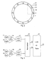
- Figure 2 schematically shows the magnet ring 7 seen from the end of the device and shows the positions of a first 21, a second 22, a third 23, and a fourth 24 Hall element in the sealed circuit block 10 relative to the poles of the magnet ring 7.
- This position can be seen as a start position from which the button is screwed away during the setting of a dose and to which the button returns when a set dose has been injected.
- the ring 7 is magnetised to present along it perimeter a sinus shaped magnetic field oscillating 360° between two poles having the same polarity. With twelve poles along the perimeter of the ring a 360° magnetic angle will correspond to a 60° rotation of the button 1.
- the Hall elements 21-24 works together with the magnet ring 7 to monitor the relative rotation of the button 1 relative to the drum 6 as the length of this rotation is proportional with the number of doses injected.
- this monitoring Is made by leading the output signal from the first 21 and the third 23 Hall elements to the inputs of a differential operational amplifier 25 as shown in figure 3.
- phase angle is calculated relative to the magnet poles so that a rotation which brings a Hall element from a pole with one polarity to the next pole with the same polarity is defined as a phase angle of 360° which in the shown example corresponds to a 60° rotation of the drum 6.
- the second 22 and the fourth 24 Hall element is coupled to the inputs of a differential operational amplifier 26 from which the output signal which is proportional with the sinus of phase angle is sent through an analogue/digital converter 28.
- the signals from the AD converters 27 and 28 are normalised in a circuit 29 which has two output terminals 30 and 31 which gives off signals which can address a look up table in a circuit 32 to provide at an output 33 an output signal indicating the rotation angle of the drum 6 relative to the button 1.
- the output from the table can be used for calculating the number of units which have been injected.
- the operational amplifiers 25 and 26, the A/D converters 27 and 28, the normalising circuit and the look up table can all be integrated in the sealed circuit block.
- the output signal from the table 32 can also internally in the circuit block 10 be stored in a storage from which a likewise integrated driver for the display 14 is driven to make the display shown the latest injected dose.
Landscapes
- Health & Medical Sciences (AREA)
- Vascular Medicine (AREA)
- Engineering & Computer Science (AREA)
- Anesthesiology (AREA)
- Biomedical Technology (AREA)
- Heart & Thoracic Surgery (AREA)
- Hematology (AREA)
- Life Sciences & Earth Sciences (AREA)
- Animal Behavior & Ethology (AREA)
- General Health & Medical Sciences (AREA)
- Public Health (AREA)
- Veterinary Medicine (AREA)
- Infusion, Injection, And Reservoir Apparatuses (AREA)
- Measurement Of Length, Angles, Or The Like Using Electric Or Magnetic Means (AREA)
Abstract
Description
- The invention relates to electrically controlled injection devices for injecting medical preparations in the human body.
- For patients suffering from diseases, which provoke the need for frequent administration of liquid medicine which is injected or infused into the patient, administration devices has been developed in the form of syringes by which a dose of medicine can easily be set and successively injected by the patient himself. Also pumps have been developed which pumps continuously or semi continuously, i. e. in repetitive small doses, infuse a small flow of the medicine through a catheter into the body of the patient.
- To work automatically the pumps have to be equipped with a power supply which can drive the pump. The power supply is mainly an electric battery supplying an electric motor driving a piston into a cartridge to successively press out the content thereof through the catheter. However, pumps may be differently designed as membrane pumps or as another kind of cyclic working pumps, but common to most pumps is, that they are electric powered from an electric battery and controlled by an electric circuit, which is programmed to power the pump in a way ensuring the administration of the correct flow of medicine. The electric circuit can further receive information from sensors distributed in the pump to survey that the pump is working properly and the circuit can control the powering in a way which promotes the correct working.
- Originally syringes were mechanically working devices on which the patient could set a wanted dose and thereafter inject the dose by manually pressing down an injection button. In the device described in
WO 9730742 - As described in
WO 9733638 - The electronic circuit may be a common commercial circuit or an integrated circuit block which is designed and manufactured specifically to be used in the device in question. Once such an integrated circuit block has left the production line as a functioning circuit it is very reliable, and failing of the device is mainly due to the wiring and connections to sensors outside the circuit. Especially sensors based on mechanical contacts are rather sensible to wear, dust and oxidation.
- Adressing this problem, electronically monitored devices by which a dose of medicine can be set and injected and in which device wiring and connections outside a sealed integrated electric circuit are reduced to a minimum, e. g. to terminals for connection to a power source and an output to a display which commonly will be large relative to the circuit may be provided.
- An injection device employing optical, magnetic, piezoelectric, or other means is known from
EP 1 095 668EP 1 095 668 - Consequently an objective of the invention is to provide an injection device having an electronic display for displaying information relating to actual injected doses where the doses delivered are monitored correctly.
- This is obtained by an injection device according to
claim 1. - The sensors can be light sensors, e. g. photocells, magnetic sensors, e. g. Hall elements, or coils in which a current is induced by an outer magnetic field, load cells which gives of an electric signal when they sense a mechanical pressure. Common to all these sensors are that their electric conditions are changed without involving any wear and dirt sensible switches. Even emission of light can be obtained by the sealed electronic circuit block by establishing of so-called laser wells.
- The sealed circuit block, a power supply for this circuit block, and other electronic components connected to said circuit block may be accommodated in one rigid part of the device. Thereby movable electric connections are avoided.
- The rigid part of the device may appropriately be a button which can be used for setting or injecting a dose of a medicine.
- At least one of the sensors may be a Hall element.
- Such a Hall element may be signalled by a movable magnet fixed to a part of the device to monitor the position of this part relative to the part accommodating the electronic circuit block.
- The sealed electronic circuit block may comprise a timer which may have a first input for a reset signal, a second input for a signal activating a read out of the timer, and an output to a display displaying the read out of the time lapsed after the latest receipt of a signal on said first input, the injection device further being provided with a sensor connected to the first input of said timer, which sensor gives off a signal when the injection button is pressed to move the piston rod, and with a means for optional sending of a signal to the second input to activate the read out of the electronic circuit.
- The electronic circuit in the sealed circuit block may be so designed that a signal sent to said second input opens the energising of the Hall element and other energy consuming sensors. This way the Hall element and other sensors may be energised only when they are going to perform a monitoring function whereas they are switched off when the device is stored. During storage power is still supplied to the timer and memory functions.
- The circuit may further be so designed that a signal is sent to said first input when a Hall element in the sealed electronic circuit block detects a change of the position of a magnet relative to the part accommodating the sealed electronic circuit block.
- The means optionally sending a signal to the second input may be a switch outside the sealed electronic circuit block. This switch may be a conventional switch in the power supply for the Hall element.
- When the device is so designed that the Hall element is not activated during the setting of a dose but is activated during the injection it can count the number of units injected and may at the same time send a signal to said first input.
- The magnet may have the shape of a ring having a number of alternating poles along its perimeter
- To measure the size of an injected dose it is necessary to measure the extent of the rotation of the magnet ring relative to the button accommodating the sealed circuit block. This is obtained by using a number of Hall elements positioned along an arc of a circle which follows a section of said magnet ring. At the start of the rotation the relative position of the magnet ring relative to Hall elements is defined by the magnetic field which is detected by the Hall elements.
On the basis of the field measured a relative angle, the start angle, is calculated. By rotation the field measured varies with the rotation angle and at the end of the rotation the relative angle, the end angle, is calculated. These angles can be found in a table over corresponding detected magnetic fields and angular positions. Such a table can be included in the sealed circuit block. Further it is detected how many times poles having the same polarity are passed and each time this happens the angle between two poles with the same polarity is added to the rotation angle, which is calculated as the end angle minus the start angle. Knowing the number of units which are injected by a 360° rotation the rotation angle can easily be converted to injected units. - In an embodiment of the device according to the
invention 4 Hall elements may be used and the magnet ring may have 12 poles. The Hall elements may be so distributed along an arc of a circle that, a first Hall element is positioned facing a north pole a third Hall element is facing a neighbour south pole, a second Hall element is facing the neutral zone between said north pole and said south pole, and a fourth Hall element is facing the neutral zone between said south pole and the succeeding north pole, i. e. the length of the circular arc is 45°. - The magnet poles of the magnet ring creates a sine shaped magnet field with a full sine wave for each pair of poles. With 12 poles on the magnet ring a phase angle of 360° for the sine curve corresponds to 60° of rotation. With the Hall elements placed as described the phase angle at the respective positions of the Hal elements are 0°, 90°,180°, and 270°, repectively.
- The outputs from the first and the third Hal element may be connected to input terminals on a first differential operational amplifier and the outputs from the second and the fourth Hall elements are connected to input terminals on a second differential operational amplifier, and output signals from the differential operational amplifiers are through analogue/digital converters and a normalising circuit lead to a look up table circuit wherein one signal is divided with the other to obtain a tangent function which is used as entrance to a table.
- By coupling the Hall elements which are magnetically 180° displaced relative to each other to a differential amplifier immunity against external magnetic fields is obtained. By the 90° displacement between a first set of Hall elements, comprising the first and the third Hall element, and the second set of Hall elements, comprising the second and the fourth Hall element a quadrature measurement is obtained by which one signal is a sine signal and another is a cosine signal. By division of these signals an tangent function is obtained. As tangent value is independent of the amplitudes of the sine and the cosine signals the sensor will be insensitive to variations in the magnetic field strength and consequently independent of the air gap between the magnet ring and the sensor. The tangent value obtained refers to a magnetic angle which can be found in the table. Also account must be taken for the number of times a 360° magnetic cycle has been run through. On the basis hereof the rotation angle for the dose setting drum can be found when the number of poles on the ring is known.
- In the following the invention is described in further details with references to the drawing, wherein
- Figure 1
- shows a detail of an injection device with an integrated circuit block according to the invention
- Figure 2
- shows schematically the relative positioning of a magnet ring and a sealed circuit block containing four Hall elements.
- Figure 3
- shows a block diagram of the integrated circuit transforming the readings of the Hall elements into a rotation angle of the dosing mechanism.
- Figure 1 shows the proximal end of an injection device comprising a combined dose setting and
injection button 1, which button is rotated to set a dose and pressed in an axial direction to inject the set dose. Thebutton 1 is fixed to atubular element 2 so thatelement 2 will follow as well rotational as axial movements of thebutton 1. - When the
button 1 is rotated to set a dose thetubular element 2 is rotated too. Thetubular element 2 has aflange 3 carrying a number of ^-shapedteeth 4 which engages corresponding depressions in an internalcircumferential flange 5 in adose setting drum 6 concentric with thetubular element 2 so that saiddrum 6 is rotated with saidtubular element 2 and thebutton 1 when said button is rotated to set a dose. When thedose setting drum 6 is rotated it will, due to a not shown thread connection between saiddrum 6 and a not shown housing concentrically surrounding saiddose setting drum 6 and saidtubular element 2, be screwed outward in said housing and will lift thebutton 1 up from the end of said housing. - The
button 1 accommodates an electronic unit mounted on acircuit board 15 and comprising a sealedcircuit block 10, which is powered by abattery 11 throughcontacts circuit block 10 output signals are fed through a multi wire cable to aLCD display 14. Further the sealedcircuit block 10 has an integrated magneticsensible component 17 which can give off a signal when it is moved relative to amagnet ring 7 at the upper end of thedose setting drum 6. Themagnetic ring 7 is magnetised to have a number of alternating magnetic poles along its perimeter. When the dose-setting drum rotates relative to thebutton 1 thesensor 17 will give off a signal reflecting the magnetic field sensed by this sensor. The end wall of thebutton 1 is provided with awindow 8 made from a transparent material to allow inspection of thedisplay 14. - The electronic circuit in the sealed
circuit block 10 comprises a timer which is started when a dose is injected and the status of which is shown for a while in thedisplay 14 when thebutton 1 is pressed by pressing thewindow 8 so that the electronic unit in thebutton 1 is moved against the force of a spring, whereby a a button of a switch is pressed to activate said switch. - When the switch it activated it may give off a signal inducing a read out of the stop-watch. When the
sensor 17 is a Hall element the switch can be a main switch opening for the energising of this Hall element. - Injection is detected by the
sensor 17 when thering 7 with alternating magnetic poles is rotated relative to thebutton 1. During the setting of a dose such relative rotation is not performed. At the beginning of its movement the button is moved axially relative to thedose setting drum 6 until theteeth 4 on theflange 3 of thetubular element 2 are moved out of engagement with the depressions in theflange 5 of thedose setting drum 6. - When the
button 1 is pressed the activation of the switch will provide a signal which directly or indirectly triggers thecircuit block 10 to activate thedisplay 14 for a while to show the status of the timer. As a test all segments are shortly turned on to show that they are all operative before information is shown. - If a dose has been set, further pressing of the
button 1 will bring theteeth 4 out of engagement with the depressions in theflange 5 on thedose setting drum 6 whereby said dose setting drum is allowed to rotate relative to thebutton 1 which relative rotation is detected by the sensor17 which generates a signal in the integratedcircuit block 10 indicating that an injection is made. When thebutton 1 is released after an injection all the segments are shortly turned on one by one. - The described embodiment allows integration of all electronic components in the
button 1 so that only themagnet ring 7 must be provided in the device outside the button. In other embodiments wherein no parts rotate during injection, injection may be detected by using a sensor sensing the movement of a piston rod, which is magnetised with alternating poles. In still other embodiments wherein the button always follows the rotation of the dose-setting drum the rotation to be detected may be the relative rotation between the button and a finger pad at the end of the button, which finger pad follows the button during the dose setting but relative to which the button is rotated during injection. The circuit may be so programmed that such relative movement is only taken as an indication of an injection when the button is pressed. - Although only magnetic acting signal generators are mentioned the use of other, e. g. optical signal generators and sensors lies within the scope of the invention. Also the button in which the electric components are integrated, although it is described as a fixed part of the device, may be removable so that it can be moved from a possible disposable injection device and mounted on a new one, only the devices must be provided with the necessary signaller to generate signals from the sensors. This may appropriately be obtained by moulding such signallers into the syringes by using a mouldable magnetic plastic material.
- Figure 2 schematically shows the
magnet ring 7 seen from the end of the device and shows the positions of a first 21, a second 22, a third 23, and a fourth 24 Hall element in the sealedcircuit block 10 relative to the poles of themagnet ring 7. This position can be seen as a start position from which the button is screwed away during the setting of a dose and to which the button returns when a set dose has been injected. In the shown embodiment thering 7 is magnetised to present along it perimeter a sinus shaped magnetic field oscillating 360° between two poles having the same polarity. With twelve poles along the perimeter of the ring a 360° magnetic angle will correspond to a 60° rotation of thebutton 1. - When energised during the injection of a set dose the Hall elements 21-24 works together with the
magnet ring 7 to monitor the relative rotation of thebutton 1 relative to thedrum 6 as the length of this rotation is proportional with the number of doses injected. In the embodiment shown in figure 2 this monitoring Is made by leading the output signal from the first 21 and the third 23 Hall elements to the inputs of a differentialoperational amplifier 25 as shown in figure 3. The output signal from theoperational amplifier 24, which is an analogue signal proportional with the cosines of the phase angle of the rotation relative to the start position, is digitised by anAD converter 27. It shall be noticed that this phase angle is calculated relative to the magnet poles so that a rotation which brings a Hall element from a pole with one polarity to the next pole with the same polarity is defined as a phase angle of 360° which in the shown example corresponds to a 60° rotation of thedrum 6. - Similarly the second 22 and the fourth 24 Hall element is coupled to the inputs of a differential operational amplifier 26 from which the output signal which is proportional with the sinus of phase angle is sent through an analogue/
digital converter 28. The signals from theAD converters circuit 29 which has twooutput terminals circuit 32 to provide at anoutput 33 an output signal indicating the rotation angle of thedrum 6 relative to thebutton 1. When the number of units to be injected per 360° rotation of thedrum 6 is decided the output from the table can be used for calculating the number of units which have been injected. - The
operational amplifiers 25 and 26, the A/D converters circuit block 10 be stored in a storage from which a likewise integrated driver for thedisplay 14 is driven to make the display shown the latest injected dose. - Other distributions and numbers of magnetic poles, other numbers and constellations of sensors, and other handling and calculating circuits can be used without deviating from the scope of the invention.
Claims (15)
- An electrically controlled device for injecting medical preparations in the human body, the device comprising:- first button means (1) for setting a dosage of medicine to be injected and second button means (1) for injecting a set dosage when the second button means (1) is pressed, whereby responsive to the injection movement, a first part (6) of the device is moved relative to a second part (1,2) of the device,- sensors (17, 21, 22, 23, 24) integrated in a sealed circuit block (10) and accommodated in the second part (1,2) of the device, the sensors (17, 21, 22, 23, 24) being adapted in a non-contact manner to monitor the movement of the first part (6) relative to the second part (1,2),- a sealed electric circuit receiving signals from said sensors (17, 21, 22, 23, 24) and configured to calculate a dose based on the received signals, and- a display (14) for displaying information provided by said sealed electric circuit,characterised in that- the relative movement of the first part (6) relative to the second part (1,2) responsive to the injection movement is proportional to the size of the injected dose,- that the sealed electric circuit (10) is configured to calculate the size of the actually injected dose based on the monitoring of said relative movement, and- that the device is configured for displaying said actually injected dose.
- A device according to claim 1, characterised in that the sealed circuit block (10), a power supply (11) for the circuit block (10) and other electric components connected to said sealed circuit block (10) are accommodated in one rigid part (1,2) of the device.
- A device according to claim 2 characterised in that said rigid part (1,2) of the device is the first and the second button means (1) forming a dose setting and injection button (1) in combination.
- A device according to claim 1, 2 or 3, characterised in that at least one sensor (17, 21, 22, 23, 24) is a Hall element.
- A device according to claim 4, characterised in that the Hall element (17, 21, 22, 23, 24) is signalled by a magnet (7) fixed to a part (6) of the device to monitor the position of this part (6) movable relative to the part (1,2) accommodating the sealed circuit block (10).
- A device according to claim 4 or 5, charaterised in that the sealed circuit block (10) comprises a timer and has a first input for a reset signal, a second input for a signal activating a read out of the electronic circuit, and an output to a display (14) displaying the read out of the time lapsed after the latest receipt of a signal on said first input, the sealed circuit block (10) further being provided with a sensor (17, 21, 22, 23, 24) connected to said first input, which sensor gives off a signal when the second button means (1) is pressed to inject a set dose, and with a means for optional sending a signal to the second input to activate the read out of the electronic circuit.
- A device according to claim 6, characterised in that the sealed electronic circuit is so designed that a signal sent to the second input opens the energizing of the Hall element (17, 21, 22, 23, 24) and other energy consuming sensors.
- A device according to claim 6 or 7, characterised in that the Hall element (17, 21, 22, 23, 24) is designed to send a signal to the first input when it detects a change of the position of the magnet (7) relative to the part (1,2) accommodating the sealed electric circuit.
- A device according to claim 6, 7 or 8, characterised in that the means optionally sending the second signal is a switch outside the sealed circuit block (10).
- A device according to anyone of the previous claims 5 - 9, characterised in that the magnet has the shape of a magnet ring (7) presenting a sinus shaped magnetic field along the perimeter.
- A device according to claim 10, characterised in that a number of Hall elements (17, 21, 22, 23, 24) are provided, which Hall elements are positioned along a circle arc which follows a section of said magnet ring (7).
- A device according to claim 11, characterised in that four Hall elements (17, 21, 22, 23, 24) are provided.
- A device according to claim 12, characterised in that the said arc of a circle corresponds to 1,5 times the arc between two poles and that a first and a fourth Hall (21, 24) element are positioned at opposite ends of the arc and a second and a third Hall element (22, 23) are positioned between the ends of the arc so that the four Hall elements (17, 21, 22, 23, 24) are placed with equidistant spaces along said arc of a circle.
- A device according to anyone of the claims 10 - 13, characterised in that the number of poles is 12 and the length of the circular arc is 45°.
- A device according to claim 13 and 14, characterised in that outputs from the first and the third Hall element (21, 23) are connected to input terminals on a first differential operational amplifier (24) and the outputs from the second and the fourth Hall elements (22, 24) are connected to input terminals on a second differential operational amplifier (25), and output signals from the differential operational amplifiers (24, 25) are through analogue/digital converters (27, 28) and a normalising circuit (29) lead to a look up table circuit (32) wherein one signal is divided with the other to obtain a tangent function which is used as entrance to a table.
Priority Applications (2)
| Application Number | Priority Date | Filing Date | Title |
|---|---|---|---|
| EP07107626A EP1808193A1 (en) | 2001-02-14 | 2002-02-12 | Electronically controlled device |
| EP10178279.5A EP2319565A3 (en) | 2001-02-14 | 2002-02-12 | Electronically controlled device |
Applications Claiming Priority (3)
| Application Number | Priority Date | Filing Date | Title |
|---|---|---|---|
| DKPA200100240 | 2001-02-14 | ||
| DK200100240 | 2001-02-14 | ||
| PCT/DK2002/000098 WO2002064196A1 (en) | 2001-02-14 | 2002-02-12 | Electronically controlled injection or infusion device |
Related Child Applications (2)
| Application Number | Title | Priority Date | Filing Date |
|---|---|---|---|
| EP07107626A Division EP1808193A1 (en) | 2001-02-14 | 2002-02-12 | Electronically controlled device |
| EP07103039 Division | 2007-02-26 |
Publications (2)
| Publication Number | Publication Date |
|---|---|
| EP1361908A1 EP1361908A1 (en) | 2003-11-19 |
| EP1361908B1 true EP1361908B1 (en) | 2007-12-19 |
Family
ID=8160220
Family Applications (3)
| Application Number | Title | Priority Date | Filing Date |
|---|---|---|---|
| EP07107626A Withdrawn EP1808193A1 (en) | 2001-02-14 | 2002-02-12 | Electronically controlled device |
| EP10178279.5A Withdrawn EP2319565A3 (en) | 2001-02-14 | 2002-02-12 | Electronically controlled device |
| EP02711784A Revoked EP1361908B1 (en) | 2001-02-14 | 2002-02-12 | Electronically controlled injection or infusion device |
Family Applications Before (2)
| Application Number | Title | Priority Date | Filing Date |
|---|---|---|---|
| EP07107626A Withdrawn EP1808193A1 (en) | 2001-02-14 | 2002-02-12 | Electronically controlled device |
| EP10178279.5A Withdrawn EP2319565A3 (en) | 2001-02-14 | 2002-02-12 | Electronically controlled device |
Country Status (6)
| Country | Link |
|---|---|
| US (1) | US7008399B2 (en) |
| EP (3) | EP1808193A1 (en) |
| JP (1) | JP4278382B2 (en) |
| AT (1) | ATE381360T1 (en) |
| DE (1) | DE60224167T2 (en) |
| WO (1) | WO2002064196A1 (en) |
Cited By (1)
| Publication number | Priority date | Publication date | Assignee | Title |
|---|---|---|---|---|
| EP3727520B1 (en) * | 2017-12-21 | 2024-03-13 | Sanofi | Drug delivery device with non-contact sensor |
Families Citing this family (212)
| Publication number | Priority date | Publication date | Assignee | Title |
|---|---|---|---|---|
| ATE197408T1 (en) | 1998-01-30 | 2000-11-11 | Novo Nordisk As | A SYRINGE |
| TW453884B (en) | 1999-09-16 | 2001-09-11 | Novo Nordisk As | Dose setting limiter |
| US6663602B2 (en) * | 2000-06-16 | 2003-12-16 | Novo Nordisk A/S | Injection device |
| PT2258424E (en) * | 2001-05-16 | 2013-03-28 | Lilly Co Eli | Medication injector apparatus |
| JP2005533545A (en) | 2002-07-24 | 2005-11-10 | エム2・メディカル・アクティーゼルスカブ | Infusion pump system, infusion pump unit, infusion pump |
| US20050160858A1 (en) * | 2002-07-24 | 2005-07-28 | M 2 Medical A/S | Shape memory alloy actuator |
| WO2004056412A2 (en) * | 2002-12-23 | 2004-07-08 | M2 Medical A/S | A disposable, wearable insulin dispensing device, a combination of such a device and a programming controller and a method of controlling the operation of such a device |
| AU2003280307A1 (en) * | 2002-11-05 | 2004-06-07 | M 2 Medical A/S | A disposable wearable insulin dispensing device, a combination of such a device and a programming controller and a method of controlling the operation of such a device |
| ATE498421T1 (en) * | 2002-12-23 | 2011-03-15 | Asante Solutions Inc | FLEXIBLE PISTON ROD |
| GB0304822D0 (en) * | 2003-03-03 | 2003-04-09 | Dca Internat Ltd | Improvements in and relating to a pen-type injector |
| US9205197B2 (en) | 2003-03-03 | 2015-12-08 | Sanofi-Aventis Deutschland Gmbh | Drug delivery device dose setting mechanism |
| GB0308267D0 (en) * | 2003-04-10 | 2003-05-14 | Dca Design Int Ltd | Improvements in and relating to a pen-type injector |
| DE10330984B4 (en) * | 2003-07-09 | 2009-12-10 | Tecpharma Licensing Ag | Injection device with position sensor |
| DE10330986B4 (en) * | 2003-07-09 | 2010-01-07 | Tecpharma Licensing Ag | Non-contact scanning with magnetoresistive sensor |
| WO2005072794A2 (en) * | 2004-01-29 | 2005-08-11 | M 2 Medical A/S | Disposable medicine dispensing device |
| WO2006045523A1 (en) * | 2004-10-21 | 2006-05-04 | Novo Nordisk A/S | Medication delivery system with a detector for providing a signal indicative of an amount of an ejected dose of drug |
| ATE404233T1 (en) | 2004-10-21 | 2008-08-15 | Novo Nordisk As | INJECTION DEVICE HAVING MEANS FOR REPORTING THE TIME SINCE THE LAST INJECTION |
| DE602005018518D1 (en) | 2004-10-21 | 2010-02-04 | Novo Nordisk As | INJECTION DEVICE WITH A PROCESSOR FOR COLLECTING OUTPUT INFORMATION |
| EP1804865B1 (en) | 2004-10-21 | 2009-09-30 | Novo Nordisk A/S | Dial-down mechanism for wind-up pen |
| DE102004063664A1 (en) * | 2004-12-31 | 2006-07-20 | Tecpharma Licensing Ag | Real-time display of a device for metered administration of a product |
| EP1855744A1 (en) * | 2005-02-28 | 2007-11-21 | Novo Nordisk A/S | A dose setting mechanism for an injection device |
| WO2006105794A1 (en) | 2005-04-06 | 2006-10-12 | M 2 Medical A/S | An actuator |
| US20090043264A1 (en) * | 2005-04-24 | 2009-02-12 | Novo Nordisk A/S | Injection Device |
| US9233203B2 (en) | 2005-05-06 | 2016-01-12 | Medtronic Minimed, Inc. | Medical needles for damping motion |
| US8137314B2 (en) * | 2006-08-23 | 2012-03-20 | Medtronic Minimed, Inc. | Infusion medium delivery device and method with compressible or curved reservoir or conduit |
| US7905868B2 (en) * | 2006-08-23 | 2011-03-15 | Medtronic Minimed, Inc. | Infusion medium delivery device and method with drive device for driving plunger in reservoir |
| US20080097291A1 (en) * | 2006-08-23 | 2008-04-24 | Hanson Ian B | Infusion pumps and methods and delivery devices and methods with same |
| US8840586B2 (en) * | 2006-08-23 | 2014-09-23 | Medtronic Minimed, Inc. | Systems and methods allowing for reservoir filling and infusion medium delivery |
| US8512288B2 (en) * | 2006-08-23 | 2013-08-20 | Medtronic Minimed, Inc. | Infusion medium delivery device and method with drive device for driving plunger in reservoir |
| US8277415B2 (en) * | 2006-08-23 | 2012-10-02 | Medtronic Minimed, Inc. | Infusion medium delivery device and method with drive device for driving plunger in reservoir |
| WO2007038059A2 (en) * | 2005-09-26 | 2007-04-05 | M2 Medical A/S | Infusion pump with a drive having a ratchet and pawl combination |
| US7534226B2 (en) | 2005-09-26 | 2009-05-19 | M2 Group Holdings, Inc. | Dispensing fluid from an infusion pump system |
| US8057436B2 (en) | 2005-09-26 | 2011-11-15 | Asante Solutions, Inc. | Dispensing fluid from an infusion pump system |
| US8105279B2 (en) | 2005-09-26 | 2012-01-31 | M2 Group Holdings, Inc. | Dispensing fluid from an infusion pump system |
| US8551046B2 (en) | 2006-09-18 | 2013-10-08 | Asante Solutions, Inc. | Dispensing fluid from an infusion pump system |
| US8409142B2 (en) * | 2005-09-26 | 2013-04-02 | Asante Solutions, Inc. | Operating an infusion pump system |
| US8192394B2 (en) * | 2005-11-08 | 2012-06-05 | Asante Solutions, Inc. | Method and system for manual and autonomous control of an infusion pump |
| DE602006008494D1 (en) * | 2005-11-08 | 2009-09-24 | M2 Medical As | INFUSION PUMP SYSTEM |
| CN104162200B (en) | 2006-02-09 | 2018-03-27 | 德卡产品有限公司 | peripheral system |
| DE102006006784A1 (en) * | 2006-02-14 | 2007-08-16 | Tecpharma Licensing Ag | Metering module for injection device, has sensor element, generating magnetic field and sensor actuation element caused change in position of magnetic field of sensor element |
| US8361036B2 (en) | 2006-03-10 | 2013-01-29 | Novo Nordisk A/S | Injection device having a gearing arrangement |
| WO2007104636A1 (en) | 2006-03-10 | 2007-09-20 | Novo Nordisk A/S | An injection device and a method of changing a cartridge in the device |
| CA2645732C (en) | 2006-03-20 | 2014-12-30 | Novo Nordisk A/S | Electronic module for mechanical medication delivery devices |
| WO2007132526A1 (en) * | 2006-05-16 | 2007-11-22 | Rorze Corporation | Shuttle type conveying device, microplate feeding and collecting device, pickup device for microplate, cassette for microplate, and shelf for receiving microplate |
| ATE458517T1 (en) | 2006-05-16 | 2010-03-15 | Novo Nordisk As | TRANSMISSION MECHANISM FOR AN INJECTION DEVICE |
| BRPI0712028A2 (en) | 2006-05-18 | 2011-12-20 | Novo Nordisk As | injector with a locking means so |
| DE102006036908A1 (en) * | 2006-08-04 | 2008-02-07 | Endress + Hauser Conducta Gesellschaft für Mess- und Regeltechnik mbH + Co. KG | Measuring instrument for automation technology with one-hand operation |
| US7828764B2 (en) * | 2006-08-23 | 2010-11-09 | Medtronic Minimed, Inc. | Systems and methods allowing for reservoir filling and infusion medium delivery |
| US7794434B2 (en) * | 2006-08-23 | 2010-09-14 | Medtronic Minimed, Inc. | Systems and methods allowing for reservoir filling and infusion medium delivery |
| US7811262B2 (en) * | 2006-08-23 | 2010-10-12 | Medtronic Minimed, Inc. | Systems and methods allowing for reservoir filling and infusion medium delivery |
| US20080051765A1 (en) * | 2006-08-23 | 2008-02-28 | Medtronic Minimed, Inc. | Systems and methods allowing for reservoir filling and infusion medium delivery |
| US7789857B2 (en) * | 2006-08-23 | 2010-09-07 | Medtronic Minimed, Inc. | Infusion medium delivery system, device and method with needle inserter and needle inserter device and method |
| WO2008037801A1 (en) | 2006-09-29 | 2008-04-03 | Novo Nordisk A/S | An injection device with electronic detecting means |
| WO2008095762A1 (en) | 2007-02-05 | 2008-08-14 | Novo Nordisk A/S | Injection button |
| RU2468829C2 (en) | 2007-03-23 | 2012-12-10 | Ново Нордиск А/С | Injection device comprising lock nut |
| US8323250B2 (en) * | 2007-04-30 | 2012-12-04 | Medtronic Minimed, Inc. | Adhesive patch systems and methods |
| US8597243B2 (en) | 2007-04-30 | 2013-12-03 | Medtronic Minimed, Inc. | Systems and methods allowing for reservoir air bubble management |
| US8434528B2 (en) * | 2007-04-30 | 2013-05-07 | Medtronic Minimed, Inc. | Systems and methods for reservoir filling |
| EP2146760B1 (en) | 2007-04-30 | 2018-10-10 | Medtronic MiniMed, Inc. | Reservoir filling, bubble management, and infusion medium delivery systems and methods with same |
| US8613725B2 (en) | 2007-04-30 | 2013-12-24 | Medtronic Minimed, Inc. | Reservoir systems and methods |
| US7963954B2 (en) | 2007-04-30 | 2011-06-21 | Medtronic Minimed, Inc. | Automated filling systems and methods |
| US7959715B2 (en) | 2007-04-30 | 2011-06-14 | Medtronic Minimed, Inc. | Systems and methods allowing for reservoir air bubble management |
| US7833196B2 (en) | 2007-05-21 | 2010-11-16 | Asante Solutions, Inc. | Illumination instrument for an infusion pump |
| US7981102B2 (en) * | 2007-05-21 | 2011-07-19 | Asante Solutions, Inc. | Removable controller for an infusion pump |
| US7892199B2 (en) | 2007-05-21 | 2011-02-22 | Asante Solutions, Inc. | Occlusion sensing for an infusion pump |
| US7794426B2 (en) * | 2007-05-21 | 2010-09-14 | Asante Solutions, Inc. | Infusion pump system with contamination-resistant features |
| WO2009024562A1 (en) | 2007-08-17 | 2009-02-26 | Novo Nordisk A/S | Medical device with value sensor |
| US7717903B2 (en) | 2007-09-06 | 2010-05-18 | M2 Group Holdings, Inc. | Operating an infusion pump system |
| US7828528B2 (en) * | 2007-09-06 | 2010-11-09 | Asante Solutions, Inc. | Occlusion sensing system for infusion pumps |
| US7935076B2 (en) | 2007-09-07 | 2011-05-03 | Asante Solutions, Inc. | Activity sensing techniques for an infusion pump system |
| US7879026B2 (en) | 2007-09-07 | 2011-02-01 | Asante Solutions, Inc. | Controlled adjustment of medicine dispensation from an infusion pump device |
| US8287514B2 (en) | 2007-09-07 | 2012-10-16 | Asante Solutions, Inc. | Power management techniques for an infusion pump system |
| US7935105B2 (en) * | 2007-09-07 | 2011-05-03 | Asante Solutions, Inc. | Data storage for an infusion pump system |
| JP5728231B2 (en) | 2007-12-31 | 2015-06-03 | ノボ・ノルデイスク・エー/エス | Electronic monitoring injection device |
| US8986253B2 (en) | 2008-01-25 | 2015-03-24 | Tandem Diabetes Care, Inc. | Two chamber pumps and related methods |
| EP2113268A1 (en) | 2008-04-30 | 2009-11-04 | F. Hoffmann-Roche AG | Administering device with safety features |
| US9974904B2 (en) | 2008-05-20 | 2018-05-22 | Avant Medical Corp. | Autoinjector system |
| US8177749B2 (en) | 2008-05-20 | 2012-05-15 | Avant Medical Corp. | Cassette for a hidden injection needle |
| US8052645B2 (en) | 2008-07-23 | 2011-11-08 | Avant Medical Corp. | System and method for an injection using a syringe needle |
| US7959598B2 (en) | 2008-08-20 | 2011-06-14 | Asante Solutions, Inc. | Infusion pump systems and methods |
| RU2508922C2 (en) | 2008-08-29 | 2014-03-10 | Ново Нордиск А/С | Medical injection device with time delay indicator |
| US8408421B2 (en) | 2008-09-16 | 2013-04-02 | Tandem Diabetes Care, Inc. | Flow regulating stopcocks and related methods |
| CA2737461A1 (en) | 2008-09-19 | 2010-03-25 | Tandem Diabetes Care, Inc. | Solute concentration measurement device and related methods |
| CA2740875A1 (en) * | 2008-10-15 | 2010-04-22 | Symbios Medical Products, Llc | Electronic flow control |
| US8573027B2 (en) | 2009-02-27 | 2013-11-05 | Tandem Diabetes Care, Inc. | Methods and devices for determination of flow reservoir volume |
| US9250106B2 (en) | 2009-02-27 | 2016-02-02 | Tandem Diabetes Care, Inc. | Methods and devices for determination of flow reservoir volume |
| DE102009003721A1 (en) * | 2009-04-01 | 2010-10-07 | Medimatik Gmbh | applicator |
| US8926561B2 (en) | 2009-07-30 | 2015-01-06 | Tandem Diabetes Care, Inc. | Infusion pump system with disposable cartridge having pressure venting and pressure feedback |
| US10010678B2 (en) * | 2010-03-31 | 2018-07-03 | Emperra Gmbh E-Health Technologies | Assembly to administer insulin from a cartridge |
| USD669165S1 (en) | 2010-05-27 | 2012-10-16 | Asante Solutions, Inc. | Infusion pump |
| KR101939267B1 (en) * | 2010-07-21 | 2019-01-16 | 삼성전자주식회사 | Method and device for measuring dose in injector |
| US8852152B2 (en) | 2011-02-09 | 2014-10-07 | Asante Solutions, Inc. | Infusion pump systems and methods |
| US8454581B2 (en) | 2011-03-16 | 2013-06-04 | Asante Solutions, Inc. | Infusion pump systems and methods |
| EP2689359B1 (en) * | 2011-03-24 | 2020-11-25 | Sanofi-Aventis Deutschland GmbH | Device and method for detecting an actuation action performable with a medical device |
| EP2696918A2 (en) | 2011-04-11 | 2014-02-19 | Novo Nordisk A/S | Injection device incorporating dose monitoring |
| HUE042822T2 (en) | 2011-04-20 | 2019-07-29 | Amgen Inc | Automatic injection device |
| KR101876568B1 (en) * | 2011-06-14 | 2018-07-09 | 삼성전자주식회사 | Injector and device for detecting injection button |
| US8585657B2 (en) | 2011-06-21 | 2013-11-19 | Asante Solutions, Inc. | Dispensing fluid from an infusion pump system |
| JP6106666B2 (en) | 2011-07-07 | 2017-04-05 | ノボ・ノルデイスク・エー/エス | Drug delivery injection pen with add-on medication acquisition / display module |
| US8808230B2 (en) | 2011-09-07 | 2014-08-19 | Asante Solutions, Inc. | Occlusion detection for an infusion pump system |
| CN103957961B (en) * | 2011-10-07 | 2016-08-17 | 诺沃—诺迪斯克有限公司 | For determining the system of position of components based on 3-axis magnetic sensor |
| CA2861706A1 (en) | 2011-12-29 | 2013-07-04 | Novo Nordisk A/S | Dial-up/dial-down mechanism for wind-up pen |
| WO2013098421A1 (en) | 2011-12-30 | 2013-07-04 | Novo Nordisk A/S | A medical injection device incorporating a dose sensing device and a method of providing such dose sensor |
| WO2013153121A2 (en) * | 2012-04-10 | 2013-10-17 | Novo Nordisk A/S | Medical injection device with time delay indicator |
| USD898908S1 (en) | 2012-04-20 | 2020-10-13 | Amgen Inc. | Pharmaceutical product cassette for an injection device |
| USD808010S1 (en) | 2012-04-20 | 2018-01-16 | Amgen Inc. | Injection device |
| US9180242B2 (en) | 2012-05-17 | 2015-11-10 | Tandem Diabetes Care, Inc. | Methods and devices for multiple fluid transfer |
| US9555186B2 (en) | 2012-06-05 | 2017-01-31 | Tandem Diabetes Care, Inc. | Infusion pump system with disposable cartridge having pressure venting and pressure feedback |
| US8454557B1 (en) | 2012-07-19 | 2013-06-04 | Asante Solutions, Inc. | Infusion pump system and method |
| US8454562B1 (en) | 2012-07-20 | 2013-06-04 | Asante Solutions, Inc. | Infusion pump system and method |
| US11116892B2 (en) | 2012-08-28 | 2021-09-14 | Osprey Medical, Inc. | Medium injection diversion and measurement |
| US11219719B2 (en) | 2012-08-28 | 2022-01-11 | Osprey Medical, Inc. | Volume monitoring systems |
| US9999718B2 (en) | 2012-08-28 | 2018-06-19 | Osprey Medical, Inc. | Volume monitoring device utilizing light-based systems |
| US10413677B2 (en) | 2012-08-28 | 2019-09-17 | Osprey Medical, Inc. | Volume monitoring device |
| US9427523B2 (en) | 2012-12-10 | 2016-08-30 | Bigfoot Biomedical, Inc. | Infusion pump system and method |
| US20140276536A1 (en) | 2013-03-14 | 2014-09-18 | Asante Solutions, Inc. | Infusion Pump System and Methods |
| US10201664B2 (en) | 2013-02-19 | 2019-02-12 | Novo Nordisk A/S | Dose capturing cartridge module for drug delivery device |
| WO2014128156A1 (en) | 2013-02-19 | 2014-08-28 | Novo Nordisk A/S | Rotary sensor module with axial switch |
| EP2958612B1 (en) | 2013-02-19 | 2018-04-11 | Novo Nordisk A/S | Drug delivery device with dose capturing module |
| US9446186B2 (en) | 2013-03-01 | 2016-09-20 | Bigfoot Biomedical, Inc. | Operating an infusion pump system |
| US9173998B2 (en) | 2013-03-14 | 2015-11-03 | Tandem Diabetes Care, Inc. | System and method for detecting occlusions in an infusion pump |
| JP6336564B2 (en) | 2013-03-15 | 2018-06-06 | アムゲン・インコーポレーテッド | Drug cassette, auto-injector, and auto-injector system |
| US20140276583A1 (en) * | 2013-03-15 | 2014-09-18 | Bayer Healthcare Llc | Injection device with automatic data capture and transmission |
| TWI614041B (en) | 2013-03-15 | 2018-02-11 | 安美基公司 | Cassette for an injector |
| DK2981310T3 (en) | 2013-04-05 | 2017-10-16 | Novo Nordisk As | Dose monitoring apparatus for a drug delivery apparatus |
| PL2981312T3 (en) * | 2013-04-05 | 2018-06-29 | Novo Nordisk A/S | Logging device adapted to combine doses |
| US10105497B2 (en) | 2013-04-05 | 2018-10-23 | Novo Nordisk A/S | Drug delivery device with integrated magnetic movement indicator |
| US9446187B2 (en) | 2013-06-03 | 2016-09-20 | Bigfoot Biomedical, Inc. | Infusion pump system and method |
| US9457141B2 (en) | 2013-06-03 | 2016-10-04 | Bigfoot Biomedical, Inc. | Infusion pump system and method |
| US9561324B2 (en) | 2013-07-19 | 2017-02-07 | Bigfoot Biomedical, Inc. | Infusion pump system and method |
| JP6534666B2 (en) | 2013-11-21 | 2019-06-26 | ノボ・ノルデイスク・エー/エス | Rotational sensor assembly with space efficient design |
| EP3071260A1 (en) | 2013-11-21 | 2016-09-28 | Novo Nordisk A/S | Rotary sensor module with resynchronization feature |
| CN105764550B (en) | 2013-11-21 | 2019-12-24 | 诺和诺德股份有限公司 | Rotary Sensor Assembly with Axial Switch and Redundancy Features |
| US10569015B2 (en) | 2013-12-02 | 2020-02-25 | Bigfoot Biomedical, Inc. | Infusion pump system and method |
| US10279106B1 (en) | 2014-05-08 | 2019-05-07 | Tandem Diabetes Care, Inc. | Insulin patch pump |
| US9629901B2 (en) | 2014-07-01 | 2017-04-25 | Bigfoot Biomedical, Inc. | Glucagon administration system and methods |
| US10137246B2 (en) | 2014-08-06 | 2018-11-27 | Bigfoot Biomedical, Inc. | Infusion pump assembly and method |
| US9919096B2 (en) | 2014-08-26 | 2018-03-20 | Bigfoot Biomedical, Inc. | Infusion pump system and method |
| US10971260B2 (en) | 2014-09-14 | 2021-04-06 | Becton, Dickinson And Company | System and method for capturing dose information |
| US10704944B2 (en) | 2014-09-14 | 2020-07-07 | Becton, Dickinson And Company | System and method for capturing dose information |
| JP6637038B2 (en) * | 2014-10-03 | 2020-01-29 | ノボ・ノルデイスク・エー/エス | Pen-type drug injector and add-on module with magnetic dose sensor system and error detection |
| US20170292859A1 (en) * | 2014-10-08 | 2017-10-12 | Novo Nordisk A/S | Rotary Sensor Component and Method of Manufacture |
| JP6810689B2 (en) | 2014-10-23 | 2021-01-06 | ノボ・ノルデイスク・エー/エス | Pen-type drug delivery device with an electronic display on the clip member |
| EP3058970A1 (en) | 2015-02-19 | 2016-08-24 | Sanofi-Aventis Deutschland GmbH | Data collection device for attachment to an injection device |
| EP3067081A1 (en) * | 2015-03-12 | 2016-09-14 | Sanofi | Drug delivery device |
| JP6863958B2 (en) * | 2015-04-01 | 2021-04-21 | オスプリー メディカル,インコーポレイティド | Syringe volume monitoring system with Hall sensor |
| US9878097B2 (en) | 2015-04-29 | 2018-01-30 | Bigfoot Biomedical, Inc. | Operating an infusion pump system |
| EP4316552A3 (en) | 2015-06-09 | 2024-04-17 | Sanofi-Aventis Deutschland GmbH | Data collection apparatus for attachment to an injection device |
| EP3322461B1 (en) | 2015-07-13 | 2022-01-26 | Novo Nordisk A/S | Pen-type drug injector with end-of-dose sensor and system for registering the delivered dose |
| PT3419700T (en) | 2015-07-21 | 2023-12-12 | Biocorp Production SA | Dose control device for injectable-drug delivery devices |
| PT3419699T (en) | 2015-07-21 | 2023-09-04 | Biocorp Production SA | Dose control system for injectable-drug delivery devices and associated methods of use |
| EP3162398A1 (en) | 2015-10-30 | 2017-05-03 | Carebay Europe Ltd. | Medicament delivery device with vibration sensor |
| EP3374009B1 (en) | 2015-11-11 | 2021-01-06 | Novo Nordisk A/S | Drug delivery device with information capture |
| EP3397326B1 (en) | 2015-12-28 | 2020-08-12 | Novo Nordisk A/S | Rotary sensor assembly with low-power feature |
| US10449294B1 (en) | 2016-01-05 | 2019-10-22 | Bigfoot Biomedical, Inc. | Operating an infusion pump system |
| CN108472440B (en) | 2016-01-05 | 2021-11-09 | 比格福特生物医药公司 | Operating a multi-mode drug delivery system |
| HK1256995A1 (en) | 2016-01-14 | 2019-10-11 | Bigfoot Biomedical, Inc. | Occlusion resolution in medication delivery devices, systems, and methods |
| WO2017148855A1 (en) | 2016-03-01 | 2017-09-08 | Novo Nordisk A/S | Switch arrangement for drug delivery device with data capture |
| USD809134S1 (en) | 2016-03-10 | 2018-01-30 | Bigfoot Biomedical, Inc. | Infusion pump assembly |
| KR101870021B1 (en) * | 2016-03-24 | 2018-06-21 | 서울대학교산학협력단 | Safety syringe system |
| JP6543775B2 (en) | 2016-03-25 | 2019-07-10 | イーライ リリー アンド カンパニー | Determination of set and delivered dose in drug delivery device |
| WO2017184401A1 (en) | 2016-04-19 | 2017-10-26 | Eli Lilly And Company | Determination of a dose in a medication delivery device using two moving arrays with teeth and a sensor |
| CN109310825B (en) | 2016-06-16 | 2021-04-13 | 艾斯曲尔医疗公司 | Auxiliary devices for drug delivery devices |
| US9636464B1 (en) * | 2016-08-01 | 2017-05-02 | Innovative Precision Instruments Limited | Drug delivery device and a drug information detection device |
| EP3496790B1 (en) | 2016-08-12 | 2020-10-21 | Eli Lilly and Company | Dose sensing mechanism in a medication delivery device |
| ES2871883T3 (en) * | 2016-09-09 | 2021-11-02 | Sanofi Aventis Deutschland | Data collection apparatus for attachment to an injection device |
| EP4715554A2 (en) | 2016-09-27 | 2026-03-25 | Bigfoot Biomedical, Inc. | Medicine injection and disease management systems, devices, and methods |
| CN109996577B (en) | 2016-12-01 | 2021-10-19 | 诺和诺德股份有限公司 | Drug delivery device with torsion spring feature |
| CN109996578B (en) | 2016-12-01 | 2021-10-19 | 诺和诺德股份有限公司 | Drug delivery device with clutch feature |
| US11096624B2 (en) | 2016-12-12 | 2021-08-24 | Bigfoot Biomedical, Inc. | Alarms and alerts for medication delivery devices and systems |
| USD836769S1 (en) | 2016-12-12 | 2018-12-25 | Bigfoot Biomedical, Inc. | Insulin delivery controller |
| JP7071366B2 (en) * | 2016-12-14 | 2022-05-18 | メディミューン,エルエルシー | Multi-component sensor embedded in the plunger rod to acquire and transmit injection information |
| CA3044858C (en) | 2016-12-15 | 2022-04-26 | Eli Lilly And Company | Medication delivery device with sensing system |
| EP3348298A1 (en) | 2017-01-16 | 2018-07-18 | Novo Nordisk A/S | Drug delivery device with rotationally geared piston rod driver |
| JP7204672B2 (en) | 2017-01-25 | 2023-01-16 | バイオコープ プロダクション ソシエテ アノニム | Injectable drug delivery device dosage control system and associated method of use |
| JP7018449B2 (en) | 2017-02-01 | 2022-02-10 | ノボ・ノルデイスク・エー/エス | Rotary dose sensing module for and inside disposable pen drug delivery devices |
| JP6877168B2 (en) * | 2017-02-14 | 2021-05-26 | 日本電産サンキョー株式会社 | Rotary encoder and its absolute angle position detection method |
| LT3589340T (en) * | 2017-02-28 | 2026-01-12 | Eli Lilly And Company | Dose detection and drug identification for a medication delivery device |
| CN110582321A (en) | 2017-03-01 | 2019-12-17 | 新加坡国立大学 | A microneedle device |
| US20200086052A1 (en) | 2017-03-14 | 2020-03-19 | Novo Nordisk A/S | Cap assembly with cartridge |
| USD839294S1 (en) | 2017-06-16 | 2019-01-29 | Bigfoot Biomedical, Inc. | Display screen with graphical user interface for closed-loop medication delivery |
| EP3651647A1 (en) | 2017-07-13 | 2020-05-20 | Bigfoot Biomedical, Inc. | Multi-scale display of blood glucose information |
| EP4101485B1 (en) | 2017-08-21 | 2025-12-10 | Eli Lilly and Company | Medication delivery device with sensing system |
| US12582779B2 (en) | 2017-08-21 | 2026-03-24 | Eli Lilly And Company | Medication delivery device with rotation sensor |
| CN110958897B (en) * | 2017-08-21 | 2022-08-02 | 伊莱利利公司 | Dose detection module for a drug delivery device |
| WO2019040117A1 (en) | 2017-08-21 | 2019-02-28 | Eli Lilly And Company | Dose detection module for a medication delivery device |
| KR102665710B1 (en) | 2017-08-24 | 2024-05-14 | 노보 노르디스크 에이/에스 | GLP-1 composition and its uses |
| JP7222985B2 (en) | 2017-09-22 | 2023-02-15 | ノボ・ノルデイスク・エー/エス | Accessory device for drug delivery device |
| WO2019101962A1 (en) | 2017-11-23 | 2019-05-31 | Sanofi | Medicament injection device with rotary encoder |
| EP3720525A1 (en) | 2017-12-04 | 2020-10-14 | Novo Nordisk A/S | Drug delivery system with multipolar magnet and sensor system |
| CN108063523B (en) * | 2017-12-19 | 2024-10-29 | 深圳市哈博森科技有限公司 | Tripod head motor and rotor position angle detection method thereof |
| DK3755403T3 (en) | 2018-02-22 | 2024-09-23 | Lilly Co Eli | DRUG DELIVERY DEVICE WITH A REGISTERED ELEMENT |
| WO2019219825A1 (en) | 2018-05-18 | 2019-11-21 | Novo Nordisk A/S | Drug delivery assembly with information capture |
| CN112368039A (en) | 2018-07-10 | 2021-02-12 | 诺和诺德股份有限公司 | Rotational dose sensing module for a disposable drug delivery pen and method of assembling the same |
| US11185636B2 (en) | 2018-07-26 | 2021-11-30 | Verily Life Sciences Llc | Electrostatic rotary encoder |
| US11229749B2 (en) | 2018-09-06 | 2022-01-25 | Verily Life Sciences Llc | Plate capacitor for dosage sensing |
| CN113164690B (en) | 2018-12-04 | 2023-12-22 | 诺和诺德股份有限公司 | Drug delivery components with mobile sensor systems |
| US20200188601A1 (en) * | 2018-12-12 | 2020-06-18 | Verily Life Sciences Llc | Magnetic dosage sensing |
| EA202192026A1 (en) * | 2019-02-27 | 2021-11-12 | Эли Лилли Энд Компани | DRUG DELIVERY DEVICE WITH MEASURING SYSTEM |
| US11499841B2 (en) | 2019-04-12 | 2022-11-15 | Osprey Medical, Inc. | Energy-efficient position determining with multiple sensors |
| WO2020217076A1 (en) | 2019-04-26 | 2020-10-29 | Biocorp Production S.A. | Injection monitoring module |
| US12589209B2 (en) | 2019-06-25 | 2026-03-31 | Shl Medical Ag | System with a monitoring device |
| AU2020332803B2 (en) * | 2019-08-21 | 2023-12-14 | Eli Lilly And Company | Methods and apparatus for aspects of a dose detection system |
| CN110624160B (en) * | 2019-10-21 | 2020-11-13 | 北京糖护科技有限公司 | Digital high-precision insulin pen injection data acquisition device |
| JP7761567B2 (en) | 2020-02-18 | 2025-10-28 | ノヴォ ノルディスク アー/エス | Pharmaceutical preparations |
| CH715791A2 (en) * | 2020-03-26 | 2020-07-31 | Ypsomed Ag | Autoinjector with spill detection, process for its preparation and drive unit for it. |
| KR102394358B1 (en) * | 2020-03-30 | 2022-05-03 | 서울대학교산학협력단 | Implantable Controlled Drug Delivery Device by Magnetically Rotating Actuations |
| JP2021058653A (en) * | 2020-12-24 | 2021-04-15 | バイオコープ プロダクション エス.アー.Biocorp Production S.A. | Dose control system for injectable drug delivery devices and associated methods of use |
| CN113258741B (en) | 2021-04-22 | 2022-06-07 | 东南大学 | Method and system for detecting rotor angle of magnetic flux switching motor based on linear Hall |
| EP4309703A1 (en) | 2022-07-21 | 2024-01-24 | Ypsomed AG | An injection device comprising a releasable snap fit connection for a closure cap |
| EP4309704A1 (en) | 2022-07-21 | 2024-01-24 | Ypsomed AG | An injection device comprising a closure cap that can be removed together with an electronic module |
| EP4414006A1 (en) | 2023-02-08 | 2024-08-14 | Ypsomed AG | An injection device comprising a closure cap |
Family Cites Families (16)
| Publication number | Priority date | Publication date | Assignee | Title |
|---|---|---|---|---|
| US4634431A (en) * | 1976-11-12 | 1987-01-06 | Whitney Douglass G | Syringe injector |
| DE3104384C2 (en) * | 1981-02-07 | 1985-07-18 | Hans-Joachim 8500 Nürnberg Horn | Switch arrangement with display |
| US4515584A (en) * | 1982-07-06 | 1985-05-07 | Fujisawa Pharmaceutical Co., Ltd. | Artificial pancreas |
| US4838860A (en) * | 1987-06-26 | 1989-06-13 | Pump Controller Corporation | Infusion pump |
| US4898578A (en) * | 1988-01-26 | 1990-02-06 | Baxter International Inc. | Drug infusion system with calculator |
| US5221268A (en) * | 1991-12-06 | 1993-06-22 | Block Medical, Inc. | Multiple dose control apparatus |
| GB9309151D0 (en) * | 1993-05-04 | 1993-06-16 | Zeneca Ltd | Syringes and syringe pumps |
| US5536249A (en) * | 1994-03-09 | 1996-07-16 | Visionary Medical Products, Inc. | Pen-type injector with a microprocessor and blood characteristic monitor |
| AU1860697A (en) * | 1995-09-08 | 1997-07-28 | Visionary Medical Products Corporation | Pen-type injector drive mechanism |
| AU708528B2 (en) | 1996-02-23 | 1999-08-05 | Novo Nordisk A/S | Syringe with electronic representation of parameters |
| WO1997033638A1 (en) | 1996-03-12 | 1997-09-18 | Novo Nordisk A/S | Injection device with electronic presentation of set doses |
| CA2258308A1 (en) * | 1996-07-05 | 1998-01-15 | Novo Nordisk A/S | Dose setting device |
| US6171276B1 (en) * | 1997-08-06 | 2001-01-09 | Pharmacia & Upjohn Ab | Automated delivery device and method for its operation |
| JP3436683B2 (en) * | 1998-03-17 | 2003-08-11 | 株式会社日立ユニシアオートモティブ | Rotation angle detector |
| US6277099B1 (en) * | 1999-08-06 | 2001-08-21 | Becton, Dickinson And Company | Medication delivery pen |
| US6585698B1 (en) * | 1999-11-01 | 2003-07-01 | Becton, Dickinson & Company | Electronic medical delivery pen having a multifunction actuator |
-
2002
- 2002-02-12 WO PCT/DK2002/000098 patent/WO2002064196A1/en not_active Ceased
- 2002-02-12 AT AT02711784T patent/ATE381360T1/en not_active IP Right Cessation
- 2002-02-12 DE DE60224167T patent/DE60224167T2/en not_active Revoked
- 2002-02-12 EP EP07107626A patent/EP1808193A1/en not_active Withdrawn
- 2002-02-12 JP JP2002563988A patent/JP4278382B2/en not_active Expired - Fee Related
- 2002-02-12 EP EP10178279.5A patent/EP2319565A3/en not_active Withdrawn
- 2002-02-12 EP EP02711784A patent/EP1361908B1/en not_active Revoked
- 2002-02-13 US US10/076,025 patent/US7008399B2/en not_active Expired - Lifetime
Cited By (2)
| Publication number | Priority date | Publication date | Assignee | Title |
|---|---|---|---|---|
| EP3727520B1 (en) * | 2017-12-21 | 2024-03-13 | Sanofi | Drug delivery device with non-contact sensor |
| EP4353282A2 (en) * | 2017-12-21 | 2024-04-17 | Sanofi | Drug delivery device with non-contact sensor |
Also Published As
| Publication number | Publication date |
|---|---|
| WO2002064196A1 (en) | 2002-08-22 |
| EP1808193A1 (en) | 2007-07-18 |
| JP4278382B2 (en) | 2009-06-10 |
| DE60224167D1 (en) | 2008-01-31 |
| EP1361908A1 (en) | 2003-11-19 |
| ATE381360T1 (en) | 2008-01-15 |
| EP2319565A3 (en) | 2013-07-17 |
| US20020143288A1 (en) | 2002-10-03 |
| EP2319565A2 (en) | 2011-05-11 |
| DE60224167T2 (en) | 2008-12-04 |
| JP2004526486A (en) | 2004-09-02 |
| US7008399B2 (en) | 2006-03-07 |
Similar Documents
| Publication | Publication Date | Title |
|---|---|---|
| EP1361908B1 (en) | Electronically controlled injection or infusion device | |
| KR910009394B1 (en) | Medical pump with infusion controlled by a detachable coded label | |
| US8556847B2 (en) | Service life timer for a device for administering a product in doses | |
| EP0327209B1 (en) | Motor unit for a fluid pump | |
| US9517303B2 (en) | Reservoir plunger position monitoring and medical device incorporating same | |
| US20220296818A1 (en) | Dose sensing mechanism in a medication delivery device | |
| EP3432949B1 (en) | Determination of a dose set and delivered in a medication delivery device | |
| JPH02286169A (en) | medical pump equipment | |
| CN115209930B (en) | Drug delivery device having an improved mechanism for controlling delivery rate | |
| EP3038672A1 (en) | Device with a lavet-type motor | |
| JP2007506471A (en) | Injection device with position sensor | |
| EP2617445B1 (en) | System for medical treatment | |
| CN110711293A (en) | High precision syringe with detachable pump unit | |
| WO2010069573A2 (en) | A syringe driver | |
| EP4173658A1 (en) | Magnetic field sensor for a drug delivery device |
Legal Events
| Date | Code | Title | Description |
|---|---|---|---|
| PUAI | Public reference made under article 153(3) epc to a published international application that has entered the european phase |
Free format text: ORIGINAL CODE: 0009012 |
|
| 17P | Request for examination filed |
Effective date: 20030915 |
|
| AK | Designated contracting states |
Kind code of ref document: A1 Designated state(s): AT BE CH CY DE DK ES FI FR GB GR IE IT LI LU MC NL PT SE TR |
|
| AX | Request for extension of the european patent |
Extension state: AL LT LV MK RO SI |
|
| RIC1 | Information provided on ipc code assigned before grant |
Ipc: A61M 5/315 20060101ALI20070227BHEP Ipc: A61M 5/142 20060101AFI20070227BHEP |
|
| GRAP | Despatch of communication of intention to grant a patent |
Free format text: ORIGINAL CODE: EPIDOSNIGR1 |
|
| GRAS | Grant fee paid |
Free format text: ORIGINAL CODE: EPIDOSNIGR3 |
|
| GRAA | (expected) grant |
Free format text: ORIGINAL CODE: 0009210 |
|
| AK | Designated contracting states |
Kind code of ref document: B1 Designated state(s): AT BE CH CY DE DK ES FI FR GB GR IE IT LI LU MC NL PT SE TR |
|
| REG | Reference to a national code |
Ref country code: GB Ref legal event code: FG4D |
|
| REG | Reference to a national code |
Ref country code: IE Ref legal event code: FG4D |
|
| REG | Reference to a national code |
Ref country code: CH Ref legal event code: EP |
|
| REF | Corresponds to: |
Ref document number: 60224167 Country of ref document: DE Date of ref document: 20080131 Kind code of ref document: P |
|
| REG | Reference to a national code |
Ref country code: CH Ref legal event code: NV Representative=s name: R. A. EGLI & CO. PATENTANWAELTE |
|
| PG25 | Lapsed in a contracting state [announced via postgrant information from national office to epo] |
Ref country code: SE Free format text: LAPSE BECAUSE OF FAILURE TO SUBMIT A TRANSLATION OF THE DESCRIPTION OR TO PAY THE FEE WITHIN THE PRESCRIBED TIME-LIMIT Effective date: 20080319 |
|
| PG25 | Lapsed in a contracting state [announced via postgrant information from national office to epo] |
Ref country code: FI Free format text: LAPSE BECAUSE OF FAILURE TO SUBMIT A TRANSLATION OF THE DESCRIPTION OR TO PAY THE FEE WITHIN THE PRESCRIBED TIME-LIMIT Effective date: 20071219 Ref country code: NL Free format text: LAPSE BECAUSE OF FAILURE TO SUBMIT A TRANSLATION OF THE DESCRIPTION OR TO PAY THE FEE WITHIN THE PRESCRIBED TIME-LIMIT Effective date: 20071219 |
|
| NLV1 | Nl: lapsed or annulled due to failure to fulfill the requirements of art. 29p and 29m of the patents act | ||
| PG25 | Lapsed in a contracting state [announced via postgrant information from national office to epo] |
Ref country code: AT Free format text: LAPSE BECAUSE OF FAILURE TO SUBMIT A TRANSLATION OF THE DESCRIPTION OR TO PAY THE FEE WITHIN THE PRESCRIBED TIME-LIMIT Effective date: 20071219 |
|
| PG25 | Lapsed in a contracting state [announced via postgrant information from national office to epo] |
Ref country code: ES Free format text: LAPSE BECAUSE OF FAILURE TO SUBMIT A TRANSLATION OF THE DESCRIPTION OR TO PAY THE FEE WITHIN THE PRESCRIBED TIME-LIMIT Effective date: 20080330 |
|
| ET | Fr: translation filed | ||
| PG25 | Lapsed in a contracting state [announced via postgrant information from national office to epo] |
Ref country code: BE Free format text: LAPSE BECAUSE OF FAILURE TO SUBMIT A TRANSLATION OF THE DESCRIPTION OR TO PAY THE FEE WITHIN THE PRESCRIBED TIME-LIMIT Effective date: 20071219 |
|
| PLBI | Opposition filed |
Free format text: ORIGINAL CODE: 0009260 |
|
| PG25 | Lapsed in a contracting state [announced via postgrant information from national office to epo] |
Ref country code: PT Free format text: LAPSE BECAUSE OF FAILURE TO SUBMIT A TRANSLATION OF THE DESCRIPTION OR TO PAY THE FEE WITHIN THE PRESCRIBED TIME-LIMIT Effective date: 20080519 |
|
| PLAX | Notice of opposition and request to file observation + time limit sent |
Free format text: ORIGINAL CODE: EPIDOSNOBS2 |
|
| 26 | Opposition filed |
Opponent name: SANOFI-AVENTIS DEUTSCHLAND GMBH Effective date: 20080919 |
|
| PG25 | Lapsed in a contracting state [announced via postgrant information from national office to epo] |
Ref country code: DK Free format text: LAPSE BECAUSE OF FAILURE TO SUBMIT A TRANSLATION OF THE DESCRIPTION OR TO PAY THE FEE WITHIN THE PRESCRIBED TIME-LIMIT Effective date: 20071219 Ref country code: MC Free format text: LAPSE BECAUSE OF NON-PAYMENT OF DUE FEES Effective date: 20080228 |
|
| PG25 | Lapsed in a contracting state [announced via postgrant information from national office to epo] |
Ref country code: IE Free format text: LAPSE BECAUSE OF NON-PAYMENT OF DUE FEES Effective date: 20080212 Ref country code: GR Free format text: LAPSE BECAUSE OF FAILURE TO SUBMIT A TRANSLATION OF THE DESCRIPTION OR TO PAY THE FEE WITHIN THE PRESCRIBED TIME-LIMIT Effective date: 20080320 |
|
| PLAF | Information modified related to communication of a notice of opposition and request to file observations + time limit |
Free format text: ORIGINAL CODE: EPIDOSCOBS2 |
|
| PLAF | Information modified related to communication of a notice of opposition and request to file observations + time limit |
Free format text: ORIGINAL CODE: EPIDOSCOBS2 |
|
| PLBB | Reply of patent proprietor to notice(s) of opposition received |
Free format text: ORIGINAL CODE: EPIDOSNOBS3 |
|
| PG25 | Lapsed in a contracting state [announced via postgrant information from national office to epo] |
Ref country code: CY Free format text: LAPSE BECAUSE OF FAILURE TO SUBMIT A TRANSLATION OF THE DESCRIPTION OR TO PAY THE FEE WITHIN THE PRESCRIBED TIME-LIMIT Effective date: 20071219 |
|
| RDAF | Communication despatched that patent is revoked |
Free format text: ORIGINAL CODE: EPIDOSNREV1 |
|
| PGFP | Annual fee paid to national office [announced via postgrant information from national office to epo] |
Ref country code: CH Payment date: 20100215 Year of fee payment: 9 |
|
| RDAG | Patent revoked |
Free format text: ORIGINAL CODE: 0009271 |
|
| STAA | Information on the status of an ep patent application or granted ep patent |
Free format text: STATUS: PATENT REVOKED |
|
| REG | Reference to a national code |
Ref country code: CH Ref legal event code: PL |
|
| PGFP | Annual fee paid to national office [announced via postgrant information from national office to epo] |
Ref country code: FR Payment date: 20100223 Year of fee payment: 9 |
|
| 27W | Patent revoked |
Effective date: 20100125 |
|
| PGFP | Annual fee paid to national office [announced via postgrant information from national office to epo] |
Ref country code: DE Payment date: 20100219 Year of fee payment: 9 Ref country code: GB Payment date: 20100202 Year of fee payment: 9 |
|
| PG25 | Lapsed in a contracting state [announced via postgrant information from national office to epo] |
Ref country code: LU Free format text: LAPSE BECAUSE OF NON-PAYMENT OF DUE FEES Effective date: 20080212 |
|
| PG25 | Lapsed in a contracting state [announced via postgrant information from national office to epo] |
Ref country code: TR Free format text: LAPSE BECAUSE OF FAILURE TO SUBMIT A TRANSLATION OF THE DESCRIPTION OR TO PAY THE FEE WITHIN THE PRESCRIBED TIME-LIMIT Effective date: 20071219 |
|
| PG25 | Lapsed in a contracting state [announced via postgrant information from national office to epo] |
Ref country code: CH Free format text: LAPSE BECAUSE OF THE APPLICANT RENOUNCES Effective date: 20071219 Ref country code: LI Free format text: LAPSE BECAUSE OF THE APPLICANT RENOUNCES Effective date: 20071219 |
|
| PG25 | Lapsed in a contracting state [announced via postgrant information from national office to epo] |
Ref country code: IT Free format text: LAPSE BECAUSE OF NON-PAYMENT OF DUE FEES Effective date: 20080229 |