EP3554398B1 - Chirurgisches ultraschallinstrument mit wandlergleitgelenk - Google Patents
Chirurgisches ultraschallinstrument mit wandlergleitgelenk Download PDFInfo
- Publication number
- EP3554398B1 EP3554398B1 EP17817555.0A EP17817555A EP3554398B1 EP 3554398 B1 EP3554398 B1 EP 3554398B1 EP 17817555 A EP17817555 A EP 17817555A EP 3554398 B1 EP3554398 B1 EP 3554398B1
- Authority
- EP
- European Patent Office
- Prior art keywords
- proximal
- transducer
- coupling
- distal
- assembly
- Prior art date
- Legal status (The legal status is an assumption and is not a legal conclusion. Google has not performed a legal analysis and makes no representation as to the accuracy of the status listed.)
- Active
Links
Images


Classifications
-
- A—HUMAN NECESSITIES
- A61—MEDICAL OR VETERINARY SCIENCE; HYGIENE
- A61B—DIAGNOSIS; SURGERY; IDENTIFICATION
- A61B17/00—Surgical instruments, devices or methods
- A61B17/32—Surgical cutting instruments
- A61B17/320068—Surgical cutting instruments using mechanical vibrations, e.g. ultrasonic
-
- A—HUMAN NECESSITIES
- A61—MEDICAL OR VETERINARY SCIENCE; HYGIENE
- A61B—DIAGNOSIS; SURGERY; IDENTIFICATION
- A61B17/00—Surgical instruments, devices or methods
- A61B17/00234—Surgical instruments, devices or methods for minimally invasive surgery
-
- A—HUMAN NECESSITIES
- A61—MEDICAL OR VETERINARY SCIENCE; HYGIENE
- A61B—DIAGNOSIS; SURGERY; IDENTIFICATION
- A61B17/00—Surgical instruments, devices or methods
- A61B17/28—Surgical forceps
- A61B17/29—Forceps for use in minimally invasive surgery
-
- A—HUMAN NECESSITIES
- A61—MEDICAL OR VETERINARY SCIENCE; HYGIENE
- A61B—DIAGNOSIS; SURGERY; IDENTIFICATION
- A61B17/00—Surgical instruments, devices or methods
- A61B17/32—Surgical cutting instruments
- A61B17/320068—Surgical cutting instruments using mechanical vibrations, e.g. ultrasonic
- A61B17/320092—Surgical cutting instruments using mechanical vibrations, e.g. ultrasonic with additional movable means for clamping or cutting tissue, e.g. with a pivoting jaw
-
- A—HUMAN NECESSITIES
- A61—MEDICAL OR VETERINARY SCIENCE; HYGIENE
- A61B—DIAGNOSIS; SURGERY; IDENTIFICATION
- A61B18/00—Surgical instruments, devices or methods for transferring non-mechanical forms of energy to or from the body
- A61B18/04—Surgical instruments, devices or methods for transferring non-mechanical forms of energy to or from the body by heating
-
- A—HUMAN NECESSITIES
- A61—MEDICAL OR VETERINARY SCIENCE; HYGIENE
- A61B—DIAGNOSIS; SURGERY; IDENTIFICATION
- A61B90/00—Instruments, implements or accessories specially adapted for surgery or diagnosis and not covered by any of the groups A61B1/00 - A61B50/00, e.g. for luxation treatment or for protecting wound edges
- A61B90/03—Automatic limiting or abutting means, e.g. for safety
-
- A—HUMAN NECESSITIES
- A61—MEDICAL OR VETERINARY SCIENCE; HYGIENE
- A61N—ELECTROTHERAPY; MAGNETOTHERAPY; RADIATION THERAPY; ULTRASOUND THERAPY
- A61N7/00—Ultrasound therapy
- A61N7/02—Localised ultrasound hyperthermia
-
- A—HUMAN NECESSITIES
- A61—MEDICAL OR VETERINARY SCIENCE; HYGIENE
- A61B—DIAGNOSIS; SURGERY; IDENTIFICATION
- A61B17/00—Surgical instruments, devices or methods
- A61B2017/0046—Surgical instruments, devices or methods with a releasable handle; with handle and operating part separable
-
- A—HUMAN NECESSITIES
- A61—MEDICAL OR VETERINARY SCIENCE; HYGIENE
- A61B—DIAGNOSIS; SURGERY; IDENTIFICATION
- A61B17/00—Surgical instruments, devices or methods
- A61B2017/00477—Coupling
-
- A—HUMAN NECESSITIES
- A61—MEDICAL OR VETERINARY SCIENCE; HYGIENE
- A61B—DIAGNOSIS; SURGERY; IDENTIFICATION
- A61B17/00—Surgical instruments, devices or methods
- A61B17/28—Surgical forceps
- A61B17/29—Forceps for use in minimally invasive surgery
- A61B2017/2946—Locking means
-
- A—HUMAN NECESSITIES
- A61—MEDICAL OR VETERINARY SCIENCE; HYGIENE
- A61B—DIAGNOSIS; SURGERY; IDENTIFICATION
- A61B17/00—Surgical instruments, devices or methods
- A61B17/32—Surgical cutting instruments
- A61B17/320068—Surgical cutting instruments using mechanical vibrations, e.g. ultrasonic
- A61B2017/320069—Surgical cutting instruments using mechanical vibrations, e.g. ultrasonic for ablating tissue
-
- A—HUMAN NECESSITIES
- A61—MEDICAL OR VETERINARY SCIENCE; HYGIENE
- A61B—DIAGNOSIS; SURGERY; IDENTIFICATION
- A61B17/00—Surgical instruments, devices or methods
- A61B17/32—Surgical cutting instruments
- A61B17/320068—Surgical cutting instruments using mechanical vibrations, e.g. ultrasonic
- A61B2017/320071—Surgical cutting instruments using mechanical vibrations, e.g. ultrasonic with articulating means for working tip
-
- A—HUMAN NECESSITIES
- A61—MEDICAL OR VETERINARY SCIENCE; HYGIENE
- A61B—DIAGNOSIS; SURGERY; IDENTIFICATION
- A61B17/00—Surgical instruments, devices or methods
- A61B17/32—Surgical cutting instruments
- A61B17/320068—Surgical cutting instruments using mechanical vibrations, e.g. ultrasonic
- A61B17/320092—Surgical cutting instruments using mechanical vibrations, e.g. ultrasonic with additional movable means for clamping or cutting tissue, e.g. with a pivoting jaw
- A61B2017/320094—Surgical cutting instruments using mechanical vibrations, e.g. ultrasonic with additional movable means for clamping or cutting tissue, e.g. with a pivoting jaw additional movable means performing clamping operation
-
- A—HUMAN NECESSITIES
- A61—MEDICAL OR VETERINARY SCIENCE; HYGIENE
- A61B—DIAGNOSIS; SURGERY; IDENTIFICATION
- A61B17/00—Surgical instruments, devices or methods
- A61B17/32—Surgical cutting instruments
- A61B17/320068—Surgical cutting instruments using mechanical vibrations, e.g. ultrasonic
- A61B17/320092—Surgical cutting instruments using mechanical vibrations, e.g. ultrasonic with additional movable means for clamping or cutting tissue, e.g. with a pivoting jaw
- A61B2017/320095—Surgical cutting instruments using mechanical vibrations, e.g. ultrasonic with additional movable means for clamping or cutting tissue, e.g. with a pivoting jaw with sealing or cauterizing means
-
- A—HUMAN NECESSITIES
- A61—MEDICAL OR VETERINARY SCIENCE; HYGIENE
- A61B—DIAGNOSIS; SURGERY; IDENTIFICATION
- A61B18/00—Surgical instruments, devices or methods for transferring non-mechanical forms of energy to or from the body
- A61B2018/00315—Surgical instruments, devices or methods for transferring non-mechanical forms of energy to or from the body for treatment of particular body parts
- A61B2018/00345—Vascular system
-
- A—HUMAN NECESSITIES
- A61—MEDICAL OR VETERINARY SCIENCE; HYGIENE
- A61B—DIAGNOSIS; SURGERY; IDENTIFICATION
- A61B18/00—Surgical instruments, devices or methods for transferring non-mechanical forms of energy to or from the body
- A61B2018/00571—Surgical instruments, devices or methods for transferring non-mechanical forms of energy to or from the body for achieving a particular surgical effect
- A61B2018/00601—Cutting
-
- A—HUMAN NECESSITIES
- A61—MEDICAL OR VETERINARY SCIENCE; HYGIENE
- A61B—DIAGNOSIS; SURGERY; IDENTIFICATION
- A61B18/00—Surgical instruments, devices or methods for transferring non-mechanical forms of energy to or from the body
- A61B2018/00571—Surgical instruments, devices or methods for transferring non-mechanical forms of energy to or from the body for achieving a particular surgical effect
- A61B2018/00619—Welding
-
- A—HUMAN NECESSITIES
- A61—MEDICAL OR VETERINARY SCIENCE; HYGIENE
- A61B—DIAGNOSIS; SURGERY; IDENTIFICATION
- A61B18/00—Surgical instruments, devices or methods for transferring non-mechanical forms of energy to or from the body
- A61B2018/00571—Surgical instruments, devices or methods for transferring non-mechanical forms of energy to or from the body for achieving a particular surgical effect
- A61B2018/0063—Sealing
-
- A—HUMAN NECESSITIES
- A61—MEDICAL OR VETERINARY SCIENCE; HYGIENE
- A61B—DIAGNOSIS; SURGERY; IDENTIFICATION
- A61B90/00—Instruments, implements or accessories specially adapted for surgery or diagnosis and not covered by any of the groups A61B1/00 - A61B50/00, e.g. for luxation treatment or for protecting wound edges
- A61B90/03—Automatic limiting or abutting means, e.g. for safety
- A61B2090/031—Automatic limiting or abutting means, e.g. for safety torque limiting
Definitions
- a variety of surgical instruments include an end effector having a blade element that vibrates at ultrasonic frequencies to cut and/or seal tissue (e.g., by denaturing proteins in tissue cells). These instruments include piezoelectric elements that convert electrical power into ultrasonic vibrations, which are communicated along an acoustic waveguide to the blade element. The precision of cutting and coagulation may be controlled by the surgeon's technique and adjusting the power level, blade edge, tissue traction and blade pressure.
- ultrasonic surgical instruments examples include the HARMONIC ACE ® Ultrasonic Shears, the HARMONIC WAVE ® Ultrasonic Shears, the HARMONIC FOCUS ® Ultrasonic Shears, and the HARMONIC SYNERGY ® Ultrasonic Blades, all by Ethicon Endo-Surgery, Inc. of Cincinnati, Ohio. Further examples of such devices and related concepts are disclosed in U.S. Pat. No. 5,322,055, entitled "Clamp Coagulator/Cutting System for Ultrasonic Surgical Instruments," issued June 21, 1994 ; U.S. Pat. No.
- Some ultrasonic surgical instruments may include a cordless transducer such as that disclosed in U.S. Pub. No. 2012/0112687, entitled “Recharge System for Medical Devices,” published May 10, 2012 ; U.S. Pub. No. 2012/0116265, entitled “Surgical Instrument with Charging Devices,” published May 10, 2012 ; and/or U.S. Pat. App. No. 61/410,603, filed November 5, 2010 , entitled “Energy-Based Surgical Instruments”.
- ultrasonic surgical instruments may include an articulating shaft section and/or a bendable ultrasonic waveguide. Examples of such ultrasonic surgical instruments are disclosed in U.S. Pat. No. 5,897,523, entitled “Articulating Ultrasonic Surgical Instrument,” issued April 27, 1999 ; U.S. Pat. No. 5,989,264, entitled “Ultrasonic Polyp Snare,” issued November 23, 1999 ; U.S. Pat. No. 6,063,098, entitled “Articulable Ultrasonic Surgical Apparatus,” issued May 16, 2000 ; U.S. Pat. No. 6,090,120, entitled “Articulating Ultrasonic Surgical Instrument,” issued July 18, 2000 ; U.S. Pat. No.
- US 2013/090675 A1 describes a surgical system that includes a power supply, a connector, and a surgical instrument having a body assembly, a transmission assembly, a transducer, and a connection assembly.
- the connection assembly is configured to selectively electrically couple electrodes on the transducer with wires of the connector.
- the connection assembly may be operable in response to actuation of a trigger.
- Various connection assemblies include an extensible member that extends to contact an electrode, a rotatable member that rotates a contact into contact with an electrode, a solenoid that extends contacts coupled to each end of the solenoid into the electrodes, or a solenoid that translates a frame having contacts towards the electrodes.
- the surgical instrument may include a connection assembly having a slip ring and a weighted cable end.
- the connection assembly may include contacts on a coupleable member that may be decoupled from contacts on the transducer.
- the described devices include ultrasonic blades comprising various grasping features, devices configured to prevent ingress of surgical matter, e.g., fluid and tissue, in the space between an ultrasonic blade and an inner or outer tube distal of the distal seal, alternate closure mechanisms for ultrasonic devices, ultrasonic transducer rotation limiters to limit the rotation of an ultrasonic transducer, ultrasonic transducer rotation systems to provide unlimited continuous rotation of an ultrasonic device, integrated ultrasonic instrument electrically connected to provide RF spot coagulation with an ultrasonic (RF) generator, and coated ultrasonic/RF blades.
- RF ultrasonic
- proximal and distal are defined herein relative to a human or robotic operator of the surgical instrument.
- proximal refers the position of an element closer to the human or robotic operator of the surgical instrument and further away from the surgical end effector of the surgical instrument.
- distal refers to the position of an element closer to the surgical end effector of the surgical instrument and further away from the human or robotic operator of the surgical instrument.
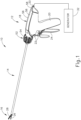
- FIG. 1 shows an exemplary ultrasonic surgical instrument (10). At least part of instrument (10) may be constructed and operable in accordance with at least some of the teachings of any of the various patents, patent application publications, and patent applications that are cited herein. As described therein and as will be described in greater detail below, instrument (10) is operable to cut tissue and seal or weld tissue (e.g., a blood vessel, etc.) substantially simultaneously.
- tissue and seal or weld tissue e.g., a blood vessel, etc.
- Instrument (10) of the present example comprises a handle assembly (12), a shaft assembly (14), and an end effector (16).
- Handle assembly (12) comprises a body (18) including a pistol grip (20) and a pair of buttons (22).
- Handle assembly (12) also includes a trigger (24) that is pivotable toward and away from pistol grip (20). It should be understood, however, that various other suitable configurations may be used, including but not limited to a scissor grip configuration.
- End effector (16) includes an ultrasonic blade (26) and a pivoting clamp arm (28).
- Clamp arm (28) is coupled with trigger (24) such that clamp arm (28) is pivotable toward ultrasonic blade (26) in response to pivoting of trigger (24) toward pistol grip (20); and such that clamp arm (28) is pivotable away from ultrasonic blade (26) in response to pivoting of trigger (24) away from pistol grip (20).
- clamp arm (28) may be coupled with trigger (24) will be apparent to those of ordinary skill in the art in view of the teachings herein.
- one or more resilient members are used to bias clamp arm (28) and/or trigger (24) to the open position shown in FIG. 1 .
- an ultrasonic transducer assembly (30) is positioned within body (18) of handle assembly (12).
- Transducer assembly (30) is coupled with a generator (32) via a power cord (33), such that transducer assembly (30) receives electrical power from generator (32).
- Power cord (33) may also be referred to as cable (33) as described herein.
- Transducer assembly (30) includes a transducer housing (114) that contains an ultrasonic transducer (34) having a plurality of piezoelectric elements (36). Piezoelectric elements (36) in transducer assembly (30) convert electrical power from generator (32) into ultrasonic vibrations.
- Generator (32) may include a power source and control module that is configured to provide a power profile to transducer assembly (30) that is particularly suited for the generation of ultrasonic vibrations through transducer assembly (30).
- generator (32) may comprise a GEN04 or GEN11 sold by Ethicon Endo-Surgery, Inc. of Cincinnati, Ohio.
- generator (32) may be constructed in accordance with at least some of the teachings of U.S. Pub. No. 2011/0087212, entitled "Surgical Generator for Ultrasonic and Electrosurgical Devices," published April 14, 2011 .
- generator (32) may be integrated into handle assembly (12), and that handle assembly (12) may even include a battery or other on-board power source such that cable (14) is omitted, while other cables may alternatively be used for electrically coupling various components. Still other suitable forms that generator (32) may take, as well as various features and operabilities that generator (32) may provide, will be apparent to those of ordinary skill in the art in view of the teachings herein.
- end effector (16) of this example comprises a clamp arm (28) and ultrasonic blade (28) as discussed briefly above.
- Clamp arm (28) includes a clamp pad (37), which faces blade (26).
- Clamp arm (28) is pivotable toward and away from blade (26) to selectively compress tissue between clamp pad (37) and blade (26).
- blade (26) is an integral feature of a distal end of an acoustic waveguide (38), which extends coaxially through tubes (40, 42), and which is configured to communicate ultrasonic vibrations to blade (26) as will be described in greater detail below.
- Shaft assembly (14) comprises an outer tube (40) and an inner tube (42).
- Outer tube (40) is operable to translate longitudinally relative to inner tube (42) to selectively pivot clamp arm (28) toward and away from blade (26).
- integral pin features (not shown) extending inwardly from respective projections (44) of clamp arm (28) pivotally secure a first portion of clamp arm (28) to a distally projecting tongue (46) of outer tube (40); while an inserted pin (48) pivotally secures a second portion of clamp arm (28) to a distally projecting tongue (50) of inner tube (42).
- tubes (40, 42) cooperate to pivot clamp arm (28) toward blade (26) when outer tube (40) is retracted proximally relative to inner tube (42).
- clamp arm (28) may be pivoted back away from blade (26) by translating outer tube (40) distally relative to inner tube (42).
- clamp arm (28) may be pivoted toward blade (26) to grasp, compress, seal, and sever tissue captured between clamp pad (37) and blade (26).
- Clamp arm (28) may be pivoted away from blade (26) to release tissue from between clamp pad (37) and blade (26); and/or to perform blunt dissection of tissue engaging opposing outer surfaces of clamp arm (28) and blade (26).
- inner tube (42) translates while outer tube (40) remains stationary to provide pivotal movement of clamp arm (28).
- shaft assembly (14) of the present example extends distally from handle assembly (12).
- a rotation control assembly (52) has rotation control member in the form of rotation control knob (54), which is secured to a proximal portion of outer tube (40).
- Knob (54) is rotatable relative to body (18), such that shaft assembly (14) is rotatable about the longitudinal axis defined by outer tube (40), relative to handle assembly (12).
- Such rotation may provide rotation of end effector (16) and shaft assembly (30) unitarily, which also includes unitary rotation of acoustic waveguide (38) coupled with transducer assembly (30) within handle assembly (12).
- various rotatable features may simply be omitted and/or replaced with alternative rotatable features, if desired.
- articulation section may take a variety of forms.
- articulation section may be configured in accordance with one or more teachings of U.S. Pub. No. 2012/0078247 .
- articulation section may be configured in accordance with one or more teachings of U.S. Pub. No. 2014/0005701 and/or U.S. Pub. No. 2014/0114334 .
- Various other suitable forms that articulation section (not shown) may take will be apparent to those of ordinary skill in the art in view of the teachings herein.
- shaft assembly (14) and end effector (16) extending distally therefrom are replaceable components.
- Shaft assembly (14) may thus be detached from handle assembly (12) after use for disposal and replaced with another assembly, such as another shaft assembly (14) and end effector (16), for further use.
- shaft assembly (14) may be integrally connected with handle assembly (12) such that the entirety of surgical instrument (10) may be reusable or simply disposable after a predetermined number of uses.
- the invention described herein is not intended to be limited to use with only replaceable or reusable components as described herein.
- handle assembly (12) is reusable as discussed above and comprises body (18) defined by a pair of complementary housings (56) joined together. Housings (56) collectively define pistol grip (20) and includes a cord support base (58) through which cable (33) extends between transducer assembly (30) and generator (32). While body (18) includes pistol grip (20) in this example, it should be understood that any other suitable kind of grip may be used.
- Waveguide (38) extends proximally through knob (54) and into body (18) to mechanically couple with transducer assembly (30).
- waveguide (38) is sufficiently coupled with transducer assembly (30)
- ultrasonic vibrations that are generated by transducer assembly (30) are communicated along waveguide (38) to reach blade (26).
- the distal end of blade (26) is located at a position corresponding to an anti-node associated with resonant ultrasonic vibrations communicated through waveguide (38), in order to tune the acoustic assembly to a preferred resonant frequency f o when the acoustic assembly is not loaded by tissue.
- transducer assembly (30) When transducer assembly (30) is energized, the distal end of blade (26) is configured to move longitudinally in the range of, for example, approximately 10 to 500 microns peak-to-peak, and in some instances in the range of about 20 to about 200 microns at a predetermined vibratory frequency f o of, for example, 55.5 kHz.
- f o a predetermined vibratory frequency
- the ultrasonic oscillation of blade (26) may simultaneously sever the tissue and denature the proteins in adjacent tissue cells, thereby providing a coagulative effect with relatively little thermal spread.
- an electrical current may also be provided through blade (26) and/or clamp pad (37) to also seal the tissue.
- knob (54) collectively rotates the remainder of shaft assembly (14), end effector (16), waveguide (38), and transducer assembly (30) relative to handle assembly (12).
- cable (33) which is electrically and mechanically coupled with transducer assembly (30), may similarly rotate in various examples to accommodate rotation of transducer assembly (30).
- cable (33) may be rigidly connected to generator (32), body (18) of handle assembly (12), or any other component, which may cause the cable (33) to wind between the rotatable transducer assembly (30) and such a rigid, non-rotatable connection.
- Such cable wind may generate a reactionary torque within cable (33) that reduces a user's ability to selectively rotate end effector (16) via knob (54) during use.
- continuous cable wind may further deteriorate the structural integrity of cable (33), resulting in decreased performance and even permanent damage to surgical instrument (10).
- transducer assembly (30) may be desirable to provide a rotatable slip coupling between transducer assembly (30) and cable (33) such that transducer assembly (30) is configured to rotate relative to cable (33) to reduce the likelihood of cable wind.
- Various alternative connectors for providing a rotatable slip coupling are described in U.S. Pat. Pub. No. 2012/0116261 and U.S. Pat. Pub. No. 2013/0090675 . While these various alternative connectors may be desirable in some instances, it will be appreciated that such alternative connectors may not be as desirable for one or more reasons depending on the particulars of the surgical instrument. The following description thus relates to a first exemplary slip joint (110) and a second exemplary slip joint (310) for use with surgical instrument (10) discussed above in greater detail.
- Each of slip joints (110, 310) is configured to electrically and mechanically connect cable (33) to transducer assembly (30) relative to the cable (33) for inhibiting cable (33) from winding upon rotation of transducer assembly (30). Accordingly, like numbers described herein indicate like features with respect to each exemplary slip joint (110, 310). It should be understood that each slip joint (110, 310) is configured to enable free rotation of transducer assembly (30) relative to cable (33) while providing continuous electrical continuity between transducer assembly (30) and cable (33).
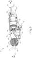
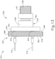
- FIGS. 3-4 show a first exemplary slip joint (110) connected with transducer assembly (30) having a transducer (112) contained within transducer housing (114), which may also be referred to as a transducer can.
- Slip joint (110) is integrated into a distal potion (116) of transducer housing (114) having a proximal hollow (118) and an adjacent distal hollow (120).
- Proximal hollow (118) extends between distal hollow (120) and a proximal opening (122) to the exterior of transducer housing (114) within body (18).
- slip joint (110) is positioned generally within distal hollow (120) and proximal hollow (122) along the longitudinal axis. More particularly, slip joint (110), distal hollow (120), and proximal hollow (122) are concentrically aligned along the longitudinal axis, and distal hollow (120) has a larger diameter than proximal hollow (122).
- Transducer housing (114) defines an outer profile about the longitudinal axis in a plane that is transverse to the longitudinal axis.
- Slip joint (110) is integrated into distal portion (116) of transducer housing (114) such that slip joint (110) is transversely sized to fit within the outer profile of transducer housing (114).
- an outer profile in the transverse plane of slip joint (110) is smaller than the outer profile of transducer housing (114) about the longitudinal axis.
- transducer (34) with piezoelectric elements (36) also defines an outer profile in the transverse plane that is smaller than the outer profile of transducer housing (114).
- the outer profile of the transducer (34) with piezoelectric elements (36) is larger than the outer profile of slip joint (110).
- the phrase "fit within” with respect to outer profiles also includes one or more outer profiles overlapping with another outer profile in addition to smaller outer profiles that "fit within.”
- an exemplary outer profile of another slip joint may be the same as an exemplary outer profile of another transducer housing and still be considered to "fit within” the outer profile of the transducer housing.
- the invention is thus not intended to be unnecessarily limited to one outer profile being smaller than an another other profile to fit therein and may include one outer profile that overlaps with another outer profile.
- Cable (33) rigidly connects to body (18) at cord support base (58), which is configured to support cable (33) in use and reduce stress concentrations from accumulating in the cable (33) at the connection with body (18).
- Cable (33) generally includes an outer cover (124) that shields at least a pair of wires (126).
- wires (126) are respectively positive and negative wires (126) that extend from generator (32) (see FIG. 1 ) for delivering electrical power therealong to transducer assembly (30) via slip joint (110). It should be understood that various other kinds of wires may also be contained in cable (33), including but not limited to wires that provide communication of data in addition to or in lieu of providing communication of operating power.
- slip joint (110) includes a proximal coupling (128) positioned in proximal hollow (118) and a distal coupling (130) positioned within distal hollow (120).
- Proximal and distal couplings (128, 130) are more particularly static and dynamic couplings (128, 130), respectively, as each relates to body (18).
- static coupling (128) is rotationally fixed about the longitudinal axis relative to body (18)
- dynamic coupling (130) is fixed with rotatable transducer housing (114) to rotate about the longitudinal axis relative to body (18).
- static coupling (128) While static coupling (128) is generally fixed so as not to rotate relative to body (18) or cable (33), alterative proximal couplings may rotate or otherwise move to some extent so long as these alternative proximal couplings are limited in movement, thereby inhibiting cable (33) from overly winding to either decrease performance and/or damage cable (33). Proximal coupling (128) is thus not intended to be unnecessarily limited to one fixed position in accordance with the invention described herein. In any case, static coupling (128) receives electrical operating power from positive and negative wires (126) and directs electrical power to dynamic coupling (130) for powering transducer assembly (30). Transducer housing (114) in turn mechanically supports static and dynamic couplings (128, 130) against each other to transmit the electrical power therebetween while providing for relative motion between static and dynamic couplings (128, 130).
- static coupling (128) includes a static body (132) having a series of annular portions narrowing in the distal direction along the longitudinal axis.
- the series of annular portions from the largest diameter proximal portion to the smallest diameter distal portion more particularly includes a proximal flange (134), an electrical potting well (136), a connection collar (138), an outer post (140), and an inner post (142).
- Static body (132) of the present example is integrally and unitarily formed of an electrically non-conductive material so as inhibit electrical power from inadvertently passing therethrough and shorting the electrical power supplied by wires (126).
- static body (132) may be alternatively formed of various components assembled together using known fasteners and/or other mechanically coupled structures.
- static body (132) is electrically non-conductive
- static coupling (128) further includes electrically conductive contacts, also referred to herein as outer and inner cable contacts (144, 146).
- Outer and inner cable contacts (144, 146), described below in additional detail, are respectively secured to outer and inner posts (140, 142) to respectively define outer and inner terminals (148, 150).
- Outer and inner terminals (148, 150) of the present example correspond to positive and negative terminals (148, 150) configured to electrically connect to positive and negative wires (126).
- alternative wiring for reversing the polarity of these terminals (148, 150) may be used as desired for properly coupling electrical power from cable (33) to transducer assembly (30) in other examples.
- Static body (132) is configured to be inserted distally through proximal opening (122) of transducer housing (114) into proximal hollow (118) until proximal flange (134) abuts against transducer housing (114) to limit further insertion.
- Proximal flange (134) also includes a pair of opposing tabs (152) configured to engage body (18) to inhibit rotation of the static body (132) relative to body (18).
- Each housing (56) includes a pair of longitudinally extending interior ribs (154) defining a longitudinal slot (156) therebetween.
- Each longitudinal slot (156) receives the respective tab (152) extending from proximal flange (134) such that static body (132) may longitudinally slide for insertion and/or removal within longitudinal slot (156), while ribs (154) rotatably engage with tabs (152) to thereby inhibit rotation of static body (132) relative to housings (56).
- electrical potting well (136) extends distally from proximal flange (134) and defines an inner bore (158) in which to mechanically mount wires (126) for electrical connection with outer and inner cable contacts (144, 146).
- a pair of contact bases (160) extend longitudinally within electrical potting well (136) about inner bore (158) and are configured to receive proximal contact members (162) of outer and inner cable contacts (144, 146), as described below in greater detail.
- Electrical potting well (136) thereby provides space for mechanically mounting wires (126), and it will be appreciated that any know structure for mounting wires (126) within electrical potting well (136), such as directly to proximal contact members (162), may be used in the system according to the invention.
- An outer surface of electrical potting well (136) is further configured to receive an annular dynamic seal (163) for inhibiting foreign matter, such as debris and/or fluid, from passing distally beyond annular dynamic seal (163) and further into proximal hollow (118).
- the proximal end of transducer housing (114) includes an annular proximal groove (164) configured to receive annular dynamic seal (163) that surrounds proximal opening (122) and is concentrically aligned along the longitudinal axis. Annular dynamic seal (163) is thereby positioned between the outer surface of electrical potting well (136) and the inner surface of transducer housing (114).
- annular dynamic seal (163) is configured to provide for relative rotation between transducer housing (114) and static coupling (128) while still inhibiting the distal passage of foreign matter toward transducer (112).
- additional seals may be used in the system according to the invention for inhibiting foreign matter from being introduced into various parts of slip joint (110) and transducer assembly (30).
- alternative examples may use more seals or even no seals so long as slip joint (110) and transducer assembly (30) are operational in view of a desirable use. The invention is thus not intended to be unnecessarily limited to the seal arrangements described herein.
- Connection collar (138) extends distally from electrical potting well (136) and includes a plurality longitudinally extending support guides (165) and a plurality of longitudinally extending snaps (166). Support guides (165) and snaps (166) are angularly positioned about connection collar (138) and alternate with one snap (166) between a pair of support guides (165) and vice versa.
- Exemplary connection collar (138) includes four support guides (165) and four snaps (166). Each snap (166) resiliently extends from electrical potting well (136) and is configured to deflect radially inward upon initial insertion into transducer housing (114), which includes an interior annular lip (168).
- proximal flange (134) approaches transducer housing (114) during insertion of static body (132)
- resilient snaps (166) bias radially outward and engage interior annular lip (168) to limit proximal translation of static body (132) relative to transducer housing (114).
- snaps (166) and proximal flange (134) of static coupling (128) cooperate respectively with interior annular lip (168) and a proximal end of transducer housing (114) to longitudinally fix static coupling (128) to transducer housing (114). While the present example includes snaps (166) for longitudinally engaging transducer housing (114), it will be appreciated that alternative fasteners may be used for such securement, and the invention described herein is not intended to be unnecessarily limited to snaps (166).
- transducer housing (114) and static coupling (128) remain configured for relative rotation. More particularly, snaps (166) longitudinally overlap with interior annular lip (168) to limit longitudinal movement, but snaps (116) provide little to no rotational engagement with transducer housing (114). Even in the event of some frictional engagement between connection collar (138) and transducer housing (114), transducer housing (114) is still configured to rotate relative to static coupling (128).
- slip joint (110) may further include various coatings on one or more surfaces prone to relative rotation therebetween to reduce friction during use. In any case, transducer housing (114) is generally configured to freely rotate on connection collar (138) as desired.
- Outer post (140) is rigidly connected to connection collar (138) radially inward from support guides (165) and extends distally therefrom.
- inner post is rigidly connected to outer post (140) radially inward therefrom and extends distally toward dynamic coupling (130).
- Each outer and inner post (140, 142) is generally cylindrical with respective distal annular surfaces (not shown). Each of the distal annular surfaces (not shown) respectively receives outer and inner cable contacts (144, 146) as shown in FIGS. 5-7 . More particularly, outer and inner cable contacts (144, 146) have respective distal annular rings (174) that circumscribe distal annular surfaces (not shown) for providing electrical connection regardless of the rotational position of dynamic coupling (130) relative to static coupling (128).
- Proximal contact members (162) extend proximally from distal annular rings (174) into electrical potting well (136) for connection with wires (126) as discussed above.
- a plurality of anchor members (176) also proximally extend from distal annular ring (174) and are configured to secure outer and inner cable contacts (144, 146) to outer and inner posts (140, 142) to form outer and inner terminals (148, 150).
- distal annular ring (174), anchor members (176), and proximal contact member (162) are unitarily and integrally formed together from an electrically conductive material and may be gold plated for additional conductivity.
- alternative construction of various components for forming outer and inner cable contacts (144, 146) may also be used with other examples. The invention described herein is thus not intended to be unnecessarily limited to the unitarily and integrally formed outer and inner cable contacts (144, 146) shown in the present example.
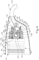
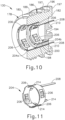
- FIGS. 4 and 8-11 show first exemplary dynamic coupling (130) in greater detail.
- dynamic coupling (130) includes a dynamic body (178) with a generally cylindrical shape.
- Dynamic body (178) includes a proximal face (180) configured to receive static coupling (128), a distal face (182) configured to abut against transducer (112), and an outer annular surface (186) configured to secure within transducer housing (114).
- Outer annular surface (186) of the present example includes a plurality of outer threads (188) that threadably engage a plurality of inner threads (190) circumscribing distal hollow (120).
- dynamic coupling (130) is rotatably driven proximally until proximal face (180) of dynamic body (178) engages a seat (192) within distal hollow (120) of transducer housing (114).
- Distal face (182) of the present example further includes a linear slot (194) for further tool grip during installation.
- a static seal (195) surrounds a portion of outer annular surface (186) within an annular groove (196) between a pair of outer annular flanges (197).
- An inner surface of dynamic body (178) thus compresses against static seal (195) for further sealing transducer (112) and inhibiting distal transmission of foreign matter across static seal (195) that may have passed by dynamic seal (163) ( see FIG. 4 ).
- Dynamic body (178) further includes an outer bore (198) and an inner bore (200).
- Outer bore (198) has a larger diameter than inner bore (200), but is generally shallower than inner bore (200).
- Outer and inner bores (198, 200) are concentrically aligned along the longitudinal axis and positioned to respectively receive outer and inner terminals (148, 150) of static coupling (128).
- outer and inner bore (198, 200) have respective annular transducer contacts (204a, 204b) mounted therein.
- Each transducer contact (204a, 204b) includes a plurality of resilient and inwardly extending contact arms (206) angularly positioned about outer and inner bores (198, 200) to extend toward and contact outer and inner cable contacts (144, 146) of static coupling (128) for electrical communication therebetween. While the exemplary transducer contacts (204a, 204b) each have four contact arms (206) equiangularly positioned about outer and inner bores (198, 200), it will be appreciated that alternative numbers and positioning for transducer contacts (204a, 204b) may be placed as desired for maintaining electrical communication with outer and inner cable contacts (144, 146).
- Each transducer contact (204a, 204b) further includes a distal contact member (208) that distally extends through proximal face (180) to distal face (182). Specifically, each distal contact member (208) distally terminates within a distal potting well (210) on distal face (182). Each distal potting well (210) is configured to provide sufficient space in which to electrically connect transducer (112) to transducer contacts (204a, 204b), such as by additional wires (212). Each transducer contact (204a, 204b) also has a pair of opposing anchor members (214) to rigidly secure each transducer contact (204a, 204b) respectively within each outer and inner bore (198, 200).
- transducer contacts (204a, 204b) define an outer profile about the longitudinal axis in a plane that is transverse to the longitudinal axis
- outer and inner cable contacts (144, 146) each respectively define outer profiles about the longitudinal axis in a plane that is transverse to the longitudinal axis.
- the outer profiles for each transducer contact (204a, 204b) and outer and inner cable contacts (144, 146) are smaller than the outer profile of transducer (34) with piezoelectric elements (36) as well as transducer housing (114).
- the outer and inner cable contacts (144, 146) are also smaller than the respective outer profiles of transducer contacts (204a, 204b).
- outer profiles of outer and inner cable contacts (144, 146) and transducer contacts (204a, 204b) are all nested within the outer profiles of transducer (34) and transducer housing (114) for reducing the size of transducer assembly (30) and slip joint (110).
- the overall size of body (18) for containing transducer assembly (30) and slip joint (110) is thus reduced about the longitudinal axis as compared to alternative slip joints that surround transducer assembly (30) for smaller, more convenient containment that may be more easily manipulated by the user.
- FIGS. 3-11 show transducer assembly (30) mechanically and electrically coupled with cable (33) via slip joint (110).
- knob (54) for positioning end effector (16) at a desirable angular orientation about the longitudinal axis of shaft assembly (14).
- the user also collectively rotates shaft assembly (14), waveguide (38), and transducer assembly (30) about the longitudinal axis of shaft assembly (14).
- Dynamic coupling (130) which is electrically and mechanically coupled with transducer (112), also rotates with transducer assembly (30), whereas static coupling (128) remains rotationally fixed relative to instrument body (18). More particularly, interior ribs (154) engage tabs (152) to inhibit rotation of static coupling (128) while longitudinally fixed within distal portion (116) of transducer housing (114) through proximal opening (122).
- contact arms (206) of transducer contacts (204a, 204b) remain radially biased against outer and inner cable contacts (144, 146) as contact arms (206) rotate about outer and inner cable contacts (144, 146). The user may thus move transducer assembly (30) to any rotational position about the longitudinal axis and contact arms (206) will remain in physical contact with outer and inner cable contacts (144, 146) to maintain electrical communication between transducer (112) and cable (33).
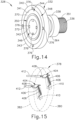
- FIGS. 12-15 show a second exemplary slip joint (310) connected with transducer assembly (30).
- Transducer assembly (30) has transducer (112) contained within a transducer housing (314).
- Slip joint (310) is integrated into a distal potion (316) of transducer housing (314) having a proximal hollow (318) and an adjacent distal hollow (320).
- Proximal hollow (318) extends between distal hollow (320) and a proximal opening (322) to the exterior of transducer housing (314) within body (18).
- slip joint (310) is positioned generally within distal hollow (320) and proximal hollow (322) along the longitudinal axis. More particularly, slip joint (310), distal hollow (320), and proximal hollow (322) are concentrically aligned along the longitudinal axis, and distal hollow (320) has a larger diameter than proximal hollow (322).
- Transducer housing (314) defines an outer profile about the longitudinal axis in a plane that is transverse to the longitudinal axis.
- Slip joint (310) is integrated into distal portion (316) of transducer housing (314) such that slip joint (310) is transversely sized to fit within the outer profile of transducer housing (314).
- an outer profile in the transverse plane of slip joint (310) is smaller than the outer profile of transducer housing (314) about the longitudinal axis.
- transducer (34) with piezoelectric elements (36) also defines an outer profile in the transverse plane that is smaller than the outer profile of transducer housing (314).
- the outer profile of the transducer (34) with piezoelectric elements (36) is larger than the outer profile of slip joint (310).
- slip joint (310) Similar to slip joint (110) ( see FIG. 4 ), slip joint (310) also includes a proximal static coupling (328) positioned in proximal hollow (318) and a distal dynamic coupling (330) positioned within distal hollow (320).
- Static coupling (328) receives electrical power from positive and negative wires (126) and directs electrical power to dynamic coupling (330) for powering transducer assembly (30).
- Transducer housing (314) in turn mechanically supports static and dynamic couplings (328, 330) against each other to transmit the electrical power therebetween while providing for relative motion between static and dynamic couplings (328, 330).
- static coupling (328) includes a static body (332) having a series of annular portions narrowing in the proximal direction along the longitudinal axis.
- the series of annular portions from the smallest diameter proximal portion to the largest diameter distal portion more particularly includes an electrical potting well (336), a cylindrical neck (338), and a distal cylindrical wall (340).
- Static body (332) of the present example is integrally and unitarily formed of an electrically non-conductive material so as inhibit electrical power from inadvertently passing therethrough and shorting the electrical power supplied by wires (126).
- static body (332) may be alternatively formed of various components assembled together using known fasteners and/or other mechanically coupled structures.
- static coupling (128) further includes outer and inner cable contacts (344, 346).
- Outer and inner cable contacts (344, 346) are respectively secured within outer and inner annular grooves (341, 342) on a distal face (343) to respectively define outer and inner terminals (348, 350).
- Outer and inner terminals (348, 350) of the present example correspond to positive and negative terminals (348, 350) configured to electrically connect to positive and negative wires (126).
- alternative wiring for reversing the polarity of these terminals (348, 350) may be used as desired for properly coupling electrical power from cable (34) to transducer assembly (30) in other examples.
- Static body (332) is configured to be inserted proximally through proximal opening (122) of transducer housing (114) by way of distal and proximal hollows (320, 318) until distal cylindrical wall (340) abuts against transducer housing (314) within distal hollow (320) to limit further insertion.
- electrical potting well (336) projects through proximal opening (322) and proximally from transducer housing (314).
- An outer surface of electrical potting well (336) includes a plurality of threads (352) configured to threadably receive a fastener, such as a wingnut (353) having a pair of opposing tabs (353) configured to engage body (18) for inhibiting rotation of wingnut (353) and static body (332) relative to body (18).
- Body (18) includes a pair of upper and lower interior ribs (354) defining a transverse slot (356) therebetween. Each transverse slot (356) receives the respective tab (353) of wingnut (352), while ribs (354) rotatably engage with tabs (353) to thereby inhibit rotation of static body (332) relative to body (18).
- Electrical potting well (336) defines an inner bore (358) in which to mechanically mount wires (126) for electrical connection with outer and inner cable contacts (344, 346).
- a pair of contact channels (360) extend longitudinally from distal face (343) through neck (338) and to electrical potting well (336) and are configured to receive proximal contact members (362) of outer and inner cable contacts (344, 346), as described below in greater detail.
- Electrical potting well (336) thereby provides space for mechanically mounting wires (126), and it will be appreciated that any know structure for mounting wires (126) within electrical potting well (336), such as directly to proximal contact members (362), may be used in the system according to the invention.
- Neck (338) extends distally from electrical potting well (36) to distal cylindrical wall (340) for a rigid connection therebetween through proximal hollow (318).
- Neck (338) is further configured to receive an annular dynamic seal (363) for inhibiting foreign matter, such as debris and/or fluid, from passing distally beyond annular dynamic seal (363) and further into proximal hollow (318).
- Neck (338) includes an annular proximal groove (364) configured to receive annular dynamic seal (363) that circumscribes proximal hollow (318) against an inner surface of transducer housing (314).
- annular dynamic seal (363) is concentrically aligned along the longitudinal axis positioned between the outer surface of neck (338) and the inner surface of transducer housing (314).
- annular dynamic seal (363) is configured to provide for relative rotation between transducer housing (314) and static coupling (328) while still inhibiting the distal passage of foreign matter fluid toward transducer (112).
- static coupling (328) is longitudinally fixed relative to transducer housing (314), but still configured for relative rotation.
- engagement surfaces prone to generate friction between static coupling (328) and transducer housing (314) may be coated in with a low-friction coating, such as silicon. Still, even in the event of some frictional engagement between static coupling (328) and transducer housing (314), transducer housing (314) is still configured to rotate relative to static coupling (328).
- Distal cylindrical wall (340) distally extends from neck (338) to a distal face (343) that includes outer and inner terminals (348, 350). More particularly, outer and inner cable contacts (344, 346) respectively include outer and inner annular rings (370, 372) having proximal contact members (362) extending proximally into electrical potting well (336) for connection with wires (126) as discussed above.
- outer annular ring (370) has a larger diameter than inner annular ring (372) and inner annular ring (372) is positioned concentrically within outer annular ring (370).
- each of the outer and inner cable contacts (344, 346) are unitarily and integrally formed from an electrically conductive material and may be gold plated for additional conductivity.
- outer and inner cable contacts (344, 346) may also be used with other examples. The invention described herein is thus not intended to be unnecessarily limited to the unitarily and integrally formed outer and inner cable contacts (344, 346) shown in the present example.
- FIGS. 12 , 13 , and 15 show first exemplary dynamic coupling (330) in greater detail.
- dynamic coupling (330) includes a dynamic body (378) with a generally cylindrical shape.
- Dynamic body (378) includes a proximal face (380) configured to receive static coupling (328), a distal face (382) configured to abut against transducer (112), and an outer annular surface (386) configured to secure within transducer housing (314).
- Outer annular surface (386) of the present example includes a plurality of outer threads (388) that threadably engage a plurality of inner threads (390) circumscribing distal hollow (320).
- dynamic coupling (330) is rotatably driven proximally until proximal face (380) of dynamic body (378) engages a seat (392) within distal hollow (320) of transducer housing (314).
- Distal face (182) of the present example further includes mechanically engageable recess (394), such as a hex recess, for tool grip during installation.
- Dynamic body (178) further includes an outer bore (398) positioned radially outward from an inner bore (400).
- Outer bore (398) radially aligns with outer cable contact (344) about the longitudinal axis
- inner bore (400) radially aligns with inner cable contact (346) about the longitudinal axis.
- Each outer and inner bore (398, 400) receives a transducer contact (404) with a plurality of resilient and proximally extending contact arms (406).
- Contact arms (406) are thereby positioned to extend proximally and contact outer and inner cable contacts (344, 346) of static coupling (328) for electrical communication therebetween.
- Each transducer contact (404) further includes a distal contact member (408) that distally extends from arms (406) from proximal face (380) to distal face (382). Specifically, each distal contact member (308) distally terminates within a distal potting well (410) on distal face (482). Each distal potting well (410) is configured to provide sufficient space in which to electrically connect transducer (412) to transducer contacts (404), such as by additional wires (412). Each transducer contact (404) also has a pair of opposing anchor members (not shown) to rigidly secure each transducer contact (404) within its respective outer and inner bore (398, 400).
- transducer contacts (404) define an outer profile about the longitudinal axis in a plane that is transverse to the longitudinal axis
- outer and inner cable contacts (344, 346) each respectively define outer profiles about the longitudinal axis in a plane that is transverse to the longitudinal axis.
- the outer profiles for each transducer contact (404) and outer and inner cable contacts (344, 346) are smaller than the outer profile of transducer (34) with piezoelectric elements (36) as well as transducer housing (414).
- outer profiles of outer and inner cable contacts (344, 346) and transducer contacts (404) are all nested within the outer profiles of transducer (34) and transducer housing (314) for reducing the size of transducer assembly (30) and slip joint (310).
- the overall size of body (18) for containing transducer assembly (30) and slip joint (310) is thus reduced about the longitudinal axis as compared to alternative slip joints that surround transducer assembly (30) for smaller, more convenient containment that may be more easily manipulated by the user.
- FIGS. 12-15 show transducer assembly (30) mechanically and electrically coupled with cable (33) via slip joint (310).
- knob (54) for positioning end effector (16) at a desirable angular orientation about the longitudinal axis of shaft assembly (14).
- the user also collectively rotates shaft assembly (14), waveguide (38), and transducer assembly (30) about the longitudinal axis of shaft assembly (14).
- Dynamic coupling (330) which is electrically and mechanically coupled with transducer (112), also rotates with transducer assembly (30), whereas static coupling (328) remains rotationally fixed relative to instrument body (18). More particularly, upper and lower interior ribs (354) engage tabs (352) to inhibit rotation of static coupling (328) while longitudinally fixed within distal portion (316) of transducer housing (314) through proximal opening (322).
- contact arms (406) of outer and inner transducer contacts (404) remain proximally biased against outer and inner cable contacts (344, 346) as contact arms (406) rotate about outer and inner cable contacts (344, 346). The user may thus move transducer assembly (30) to any rotational position about the longitudinal axis and contact arms (406) will remain in physical contact with outer and inner cable contacts (344, 346) to maintain electrical communication between transducer (112) and cable (33).
- any of the versions of instruments described herein may include various other features in addition to or in lieu of those described above.
- any of the instruments described herein may also include one or more of the various features disclosed in any of the various references that are cited.
- teachings herein may be readily applied to any of the instruments described in any of the other references cited herein, such that the teachings herein may be readily combined with the teachings of any of the references cited herein in numerous ways. Moreover, those of ordinary skill in the art will recognize that various teachings herein may be readily applied to electrosurgical instruments, stapling instruments, and other kinds of surgical instruments. Other types of instruments into which the teachings herein may be incorporated will be apparent to those of ordinary skill in the art.
- Versions of the devices described above may have application in conventional medical treatments and procedures conducted by a medical professional, as well as application in robotic-assisted medical treatments and procedures.
- various teachings herein may be readily incorporated into a robotic surgical system such as the DAVINCI TM system by Intuitive Surgical, Inc., of Sunnyvale, California.
- DAVINCI TM system by Intuitive Surgical, Inc., of Sunnyvale, California.
- teachings herein may be readily combined with various teachings of U.S. Pat. No. 6,783,524, entitled "Robotic Surgical Tool with Ultrasound Cauterizing and Cutting Instrument," published August 31, 2004 .
- Versions described above may be designed to be disposed of after a single use, or they can be designed to be used multiple times. Versions may, in either or both cases, be reconditioned for reuse after at least one use. Reconditioning may include any combination of the steps of disassembly of the device, followed by cleaning or replacement of particular pieces, and subsequent reassembly. In particular, some versions of the device may be disassembled, and any number of the particular pieces or parts of the device may be selectively replaced or removed in any combination. Upon cleaning and/or replacement of particular parts, some versions of the device may be reassembled for subsequent use either at a reconditioning facility, or by a user immediately prior to a procedure.
- reconditioning of a device may utilize a variety of techniques for disassembly, cleaning/replacement, and reassembly. Use of such techniques, and the resulting reconditioned device, are all within the scope of the present application.
- versions described herein may be sterilized before and/or after a procedure.
- the device is placed in a closed and sealed container, such as a plastic or TYVEK bag.
- the container and device may then be placed in a field of radiation that can penetrate the container, such as gamma radiation, x-rays, or high-energy electrons.
- the radiation may kill bacteria on the device and in the container.
- the sterilized device may then be stored in the sterile container for later use.
- a device may also be sterilized using any other technique known in the art, including but not limited to beta or gamma radiation, ethylene oxide, or steam.
Landscapes
- Health & Medical Sciences (AREA)
- Life Sciences & Earth Sciences (AREA)
- Surgery (AREA)
- Engineering & Computer Science (AREA)
- General Health & Medical Sciences (AREA)
- Nuclear Medicine, Radiotherapy & Molecular Imaging (AREA)
- Biomedical Technology (AREA)
- Veterinary Medicine (AREA)
- Public Health (AREA)
- Animal Behavior & Ethology (AREA)
- Heart & Thoracic Surgery (AREA)
- Molecular Biology (AREA)
- Medical Informatics (AREA)
- Dentistry (AREA)
- Mechanical Engineering (AREA)
- Oral & Maxillofacial Surgery (AREA)
- Radiology & Medical Imaging (AREA)
- Pathology (AREA)
- Plasma & Fusion (AREA)
- Otolaryngology (AREA)
- Ophthalmology & Optometry (AREA)
- Physics & Mathematics (AREA)
- Surgical Instruments (AREA)
- Ultra Sonic Daignosis Equipment (AREA)
Claims (15)
- Chirurgisches Instrument, umfassend:(a) einen Instrumentenkörper (18);(b) eine Ultraschallwandlerbaugruppe (30), die drehbar entlang einer Längsachse innerhalb des Instrumentenkörpers montiert ist, sodass die Ultraschallwandlerbaugruppe so konfiguriert ist, dass sie sich um die Längsachse dreht, wobei die Ultraschallwandlerbaugruppe ein erstes Außenprofil um die Längsachse in einer Ebene definiert, die quer zur Längsachse verläuft;(c) ein Stromkabel (33), das aus dem Instrumentenkörper herausragt und so konfiguriert ist, dass es elektrische Energie für die Ultraschallwandlerbaugruppe zum Betrieb eines akustischen Wellenleiters bereitstellt; und(d) ein Gleitgelenk des Wandlers (110), das zwischen dem Stromkabel und der Ultraschallwandlerbaugruppe positioniert ist und ein zweites Außenprofil um die Längsachse in einer Ebene definiert, die quer zur Längsachse verläuft, wobei das Gleitgelenk des Wandlers so konfiguriert ist, dass es die Elektrizität mit der Ultraschallwandlerbaugruppe elektrisch und die Energie mit der Ultraschallwandlerbaugruppe mechanisch verbindet, sodass die Ultraschallwandlerbaugruppe so konfiguriert ist, dass sie sich relativ zur Energie dreht, um zu verhindern, dass sich die Energie bei der Rotation der Ultraschallwandlerbaugruppe relativ zum Instrumentenkörper aufwickelt, wobei das zweite Außenprofil in das erste Außenprofil der Ultraschallwandlerbaugruppe passt.
- Chirurgisches Instrument nach Anspruch 1, wobei das Gleitgelenk des Wandlers Folgendes einschließt:(i) eine proximale Kupplung (328), die an dem Stromkabel befestigt ist und einen ersten Stromkabelkontakt (344) und einen zweiten Stromkabelkontakt (346) aufweist,
wobei jeder der ersten und zweiten Stromkabelkontakte elektrisch mit dem Stromkabel verbunden ist, wobei mindestens einer der ersten und zweiten Stromkabelkontakte mindestens einen distal orientierten elektrischen Kontakt bereitstellt, und(ii) eine distale Kupplung (378), die an der Ultraschallwandlerbaugruppe befestigt ist und einen ersten elektrischen Wandlerkontakt (404) und einen zweiten elektrischen Wandlerkontakt (404) aufweist,wobei jeder der ersten und zweiten elektrischen Wandlerkontakte elektrisch mit der Ultraschallwandlerbaugruppe verbunden ist, wobei mindestens einer der ersten und zweiten elektrischen Wandlerkontakte mindestens einen proximal orientierten elektrischen Kontakt (406) bereitstellt, wobei der mindestens eine distal orientierte elektrische Kontakt konfiguriert ist, um gleitend in den mindestens einen proximal orientierten elektrischen Kontakt einzugreifen,wobei die proximale und die distale Kupplung so aneinander befestigt sind, dass die distale Kupplung so konfiguriert ist, dass sie sich mit der Ultraschallwandlerbaugruppe relativ zur proximalen Kupplung dreht, während elektrische Verbindungen zwischen dem ersten elektrischen Kabelkontakt und dem ersten elektrischen Wandlerkontakt sowie dem zweiten elektrischen Kabelkontakt und dem zweiten elektrischen Wandlerkontakt aufrechterhalten werden. - Chirurgisches Instrument nach Anspruch 2, wobei die proximalen und distalen Kupplungen axial entlang der Längsachse positioniert sind, sodass die distale Kupplung so konfiguriert ist, dass sie sich relativ zur proximalen Kupplung um die Längsachse dreht.
- Chirurgisches Instrument nach Anspruch 3, wobei die proximale und die distale Kupplung ferner so aneinander befestigt sind, dass die proximale Kupplung in Längsrichtung an der distalen Kupplung entlang der Längsachse fixiert ist.
- Chirurgisches Instrument nach Anspruch 4, wobei die proximale Kupplung in den Instrumentenkörper eingreift, um die Rotation der proximalen Kupplung im Instrumentenkörper zu verhindern.
- Chirurgisches Instrument nach Anspruch 5, wobei der Körper des Instruments eine Innenrippe einschließt und die proximale Kupplung ferner einen proximalen Körper und eine Lasche einschließt, die sich von dem proximalen Körper radial nach außen erstreckt, wobei die Innenrippe so konfiguriert ist, dass sie die Lasche dagegen empfängt, sodass die Innenrippe die proximale Kupplung an einer Rotation innerhalb des Instrumentenkörpers hindert.
- Chirurgisches Instrument nach Anspruch 5, wobei der Instrumentenkörper eine Innenrippe (354) einschließt und die proximale Kupplung ferner einen proximalen Körper und eine darauf geschraubte Flügelmutter (352) einschließt, wobei die Innenrippe so konfiguriert ist, dass sie die Flügelmutter dagegen empfängt, sodass die Innenrippe die Rotation der proximalen Kupplung im Instrumentenkörper verhindert.
- Chirurgisches Instrument nach Anspruch 2, wobei die Ultraschallwandlerbaugruppe ein sich entlang der Längsachse erstreckendes Wandlergehäuse (314) einschließt, wobei das Wandlergehäuse einen distalen Endabschnitt mit einem distalen Hohlraum (320) und einem angrenzenden proximalen Hohlraum (318) aufweist, wobei die distale Kupplung gegen das Wandlergehäuse innerhalb des distalen Hohlraums befestigt ist, sodass das Wandlergehäuse eine Rotation und Translation relativ zum Wandlergehäuse verhindert, wobei die proximale Kupplung gegen das Wandlergehäuse innerhalb des proximalen Hohlraums befestigt ist, sodass das Wandlergehäuse eine Translation relativ zum Wandlergehäuse verhindert und die proximale Kupplung so konfiguriert ist, dass sie sich innerhalb des Wandlergehäuses dreht.
- Chirurgisches Instrument nach Anspruch 8, wobei das Wandlergehäuse so konfiguriert ist, dass es distal die proximale Kupplung innerhalb des proximalen Hohlraums empfängt, und wobei die proximale Kupplung ein Verbindungsmerkmal einschließt, das so konfiguriert ist, dass es die proximale Kupplung in Längsrichtung innerhalb des Wandlergehäuses sichert.
- Chirurgisches Instrument nach Anspruch 9, wobei der Instrumentenkörper eine Innenrippe (354) einschließt und die proximale Kupplung ferner einen proximalen Körper und eine Lasche (353) einschließt, die sich vom proximalen Körper radial nach außen erstreckt, wobei die Innenrippe so konfiguriert ist, dass sie die Lasche dagegen empfängt, sodass die Innenrippe die proximale Kupplung an der Rotation im Instrumentenkörper hindert.
- Chirurgisches Instrument nach Anspruch 8, wobei das Wandlergehäuse eine proximale Wand aufweist und so konfiguriert ist, dass es die proximale Kupplung proximal durch den distalen Hohlraum bis in den proximalen Hohlraum empfängt, und wobei die proximale Kupplung zwischen der distalen Kupplung und der proximalen Wand festgehalten wird, um die proximale Kupplung in Längsrichtung im Wandlergehäuse zu sichern.
- Chirurgisches Instrument nach Anspruch 11, wobei der Instrumentenkörper eine Innenrippe (354) einschließt und die proximale Kupplung ferner einen proximalen Körper und eine darauf geschraubte Flügelmutter (352) einschließt, wobei die Innenrippe so konfiguriert ist, dass sie die Flügelmutter dagegen empfängt, sodass die Innenrippe die Rotation der proximalen Kupplung im Instrumentenkörper verhindert.
- Chirurgisches Instrument nach Anspruch 8, das ferner eine ringförmige dynamische Dichtung (363) umfasst, die innerhalb des proximalen Hohlraums zwischen dem Wandlergehäuse und der darin empfangenen proximalen Kupplung positioniert ist, wobei die ringförmige dynamische Dichtung so konfiguriert ist, dass sie verhindert, dass Fremdkörper weiter distal in die Ultraschallwandlerbaugruppe eingeführt werden, wenn die Ultraschallwandlerbaugruppe sich um die proximale Kupplung dreht.
- Chirurgisches Instrument nach Anspruch 2, wobei jeder der ersten und zweiten elektrischen Kabelkontakte ringförmig ist.
- Chirurgisches Instrument nach Anspruch 1, ferner umfassend:(a) eine Griffbaugruppe (12), die den Instrumentenkörper und die Ultraschallwandlerbaugruppe einschließt;(b) eine Wellenbaugruppe (14), die sich distal von der Griffbaugruppe erstreckt;(c) ein Endeffektor (16), der sich distal von der Wellenbaugruppe erstreckt; und(d) einen akustischen Wellenleiter (38), der betriebsmäßig mit der Ultraschallwandlerbaugruppe verbunden ist und sich distal von dieser entlang der Wellenbaugruppe zum Endeffektor erstreckt.
Applications Claiming Priority (2)
| Application Number | Priority Date | Filing Date | Title |
|---|---|---|---|
| US15/378,488 US9833256B1 (en) | 2016-12-14 | 2016-12-14 | Ultrasonic surgical instrument with transducer slip joint |
| PCT/US2017/063869 WO2018111563A1 (en) | 2016-12-14 | 2017-11-30 | Ultrasonic surgical instrument with transducer slip joint |
Publications (3)
| Publication Number | Publication Date |
|---|---|
| EP3554398A1 EP3554398A1 (de) | 2019-10-23 |
| EP3554398C0 EP3554398C0 (de) | 2024-07-31 |
| EP3554398B1 true EP3554398B1 (de) | 2024-07-31 |
Family
ID=60451511
Family Applications (1)
| Application Number | Title | Priority Date | Filing Date |
|---|---|---|---|
| EP17817555.0A Active EP3554398B1 (de) | 2016-12-14 | 2017-11-30 | Chirurgisches ultraschallinstrument mit wandlergleitgelenk |
Country Status (7)
| Country | Link |
|---|---|
| US (6) | US9833256B1 (de) |
| EP (1) | EP3554398B1 (de) |
| JP (1) | JP7086962B2 (de) |
| KR (1) | KR102572912B1 (de) |
| BR (1) | BR112019012145B1 (de) |
| MX (1) | MX2019006984A (de) |
| PL (1) | PL3554398T3 (de) |
Families Citing this family (25)
| Publication number | Priority date | Publication date | Assignee | Title |
|---|---|---|---|---|
| US8182501B2 (en) | 2004-02-27 | 2012-05-22 | Ethicon Endo-Surgery, Inc. | Ultrasonic surgical shears and method for sealing a blood vessel using same |
| BRPI0518171B8 (pt) | 2004-10-08 | 2021-06-22 | Ethicon Endo Surgery Inc | aparelho coagulador de pinça ultra-sônico |
| US20070191713A1 (en) | 2005-10-14 | 2007-08-16 | Eichmann Stephen E | Ultrasonic device for cutting and coagulating |
| US7621930B2 (en) | 2006-01-20 | 2009-11-24 | Ethicon Endo-Surgery, Inc. | Ultrasound medical instrument having a medical ultrasonic blade |
| US8057498B2 (en) | 2007-11-30 | 2011-11-15 | Ethicon Endo-Surgery, Inc. | Ultrasonic surgical instrument blades |
| US8808319B2 (en) | 2007-07-27 | 2014-08-19 | Ethicon Endo-Surgery, Inc. | Surgical instruments |
| US8523889B2 (en) | 2007-07-27 | 2013-09-03 | Ethicon Endo-Surgery, Inc. | Ultrasonic end effectors with increased active length |
| US9044261B2 (en) | 2007-07-31 | 2015-06-02 | Ethicon Endo-Surgery, Inc. | Temperature controlled ultrasonic surgical instruments |
| US8430898B2 (en) | 2007-07-31 | 2013-04-30 | Ethicon Endo-Surgery, Inc. | Ultrasonic surgical instruments |
| US8512365B2 (en) | 2007-07-31 | 2013-08-20 | Ethicon Endo-Surgery, Inc. | Surgical instruments |
| US10010339B2 (en) | 2007-11-30 | 2018-07-03 | Ethicon Llc | Ultrasonic surgical blades |
| US8319400B2 (en) | 2009-06-24 | 2012-11-27 | Ethicon Endo-Surgery, Inc. | Ultrasonic surgical instruments |
| US8951272B2 (en) | 2010-02-11 | 2015-02-10 | Ethicon Endo-Surgery, Inc. | Seal arrangements for ultrasonically powered surgical instruments |
| US9820768B2 (en) | 2012-06-29 | 2017-11-21 | Ethicon Llc | Ultrasonic surgical instruments with control mechanisms |
| US10226273B2 (en) | 2013-03-14 | 2019-03-12 | Ethicon Llc | Mechanical fasteners for use with surgical energy devices |
| US11020140B2 (en) | 2015-06-17 | 2021-06-01 | Cilag Gmbh International | Ultrasonic surgical blade for use with ultrasonic surgical instruments |
| US10357303B2 (en) | 2015-06-30 | 2019-07-23 | Ethicon Llc | Translatable outer tube for sealing using shielded lap chole dissector |
| US10245064B2 (en) | 2016-07-12 | 2019-04-02 | Ethicon Llc | Ultrasonic surgical instrument with piezoelectric central lumen transducer |
| USD847990S1 (en) | 2016-08-16 | 2019-05-07 | Ethicon Llc | Surgical instrument |
| US11350959B2 (en) | 2016-08-25 | 2022-06-07 | Cilag Gmbh International | Ultrasonic transducer techniques for ultrasonic surgical instrument |
| US10952759B2 (en) | 2016-08-25 | 2021-03-23 | Ethicon Llc | Tissue loading of a surgical instrument |
| US9833256B1 (en) | 2016-12-14 | 2017-12-05 | Ethicon Endo-Surgery, Llc | Ultrasonic surgical instrument with transducer slip joint |
| CN109009331B (zh) * | 2018-08-08 | 2024-02-06 | 北京安和加利尔科技有限公司 | 一种超声手术一体刀 |
| CN113813020A (zh) * | 2021-08-08 | 2021-12-21 | 蔡宇倩 | 超声刀连接手柄 |
| CN114159129B (zh) * | 2021-12-03 | 2023-12-22 | 北京安和加利尔科技有限公司 | 一种可更换刀杆的剪式超声刀 |
Family Cites Families (79)
| Publication number | Priority date | Publication date | Assignee | Title |
|---|---|---|---|---|
| US4170234A (en) * | 1977-10-11 | 1979-10-09 | Dytek Corporation | System for use with electro-surgical pencil |
| US5322055B1 (en) | 1993-01-27 | 1997-10-14 | Ultracision Inc | Clamp coagulator/cutting system for ultrasonic surgical instruments |
| US6099537A (en) * | 1996-02-26 | 2000-08-08 | Olympus Optical Co., Ltd. | Medical treatment instrument |
| JPH09299381A (ja) * | 1996-05-20 | 1997-11-25 | Olympus Optical Co Ltd | 超音波手術装置 |
| JPH10127655A (ja) * | 1996-11-06 | 1998-05-19 | Olympus Optical Co Ltd | 超音波外科手術装置 |
| US6063098A (en) | 1996-12-23 | 2000-05-16 | Houser; Kevin | Articulable ultrasonic surgical apparatus |
| US5980510A (en) | 1997-10-10 | 1999-11-09 | Ethicon Endo-Surgery, Inc. | Ultrasonic clamp coagulator apparatus having improved clamp arm pivot mount |
| US5873873A (en) | 1997-10-10 | 1999-02-23 | Ethicon Endo-Surgery, Inc. | Ultrasonic clamp coagulator apparatus having improved clamp mechanism |
| US6589200B1 (en) | 1999-02-22 | 2003-07-08 | Ethicon Endo-Surgery, Inc. | Articulating ultrasonic surgical shears |
| US6454782B1 (en) | 1998-04-13 | 2002-09-24 | Ethicon Endo-Surgery, Inc. | Actuation mechanism for surgical instruments |
| US5897523A (en) | 1998-04-13 | 1999-04-27 | Ethicon Endo-Surgery, Inc. | Articulating ultrasonic surgical instrument |
| US5989264A (en) | 1998-06-11 | 1999-11-23 | Ethicon Endo-Surgery, Inc. | Ultrasonic polyp snare |
| US6325811B1 (en) | 1999-10-05 | 2001-12-04 | Ethicon Endo-Surgery, Inc. | Blades with functional balance asymmetries for use with ultrasonic surgical instruments |
| US6204592B1 (en) * | 1999-10-12 | 2001-03-20 | Ben Hur | Ultrasonic nailing and drilling apparatus |
| US6752815B2 (en) | 2001-01-31 | 2004-06-22 | Ethicon Endo-Surgery, Inc. | Method and waveguides for changing the direction of longitudinal vibrations |
| US6986686B2 (en) * | 2001-02-23 | 2006-01-17 | Olympus Corporation | Electrical plug for supplying electric power from a power supply to a medical instrument |
| US6783524B2 (en) | 2001-04-19 | 2004-08-31 | Intuitive Surgical, Inc. | Robotic surgical tool with ultrasound cauterizing and cutting instrument |
| US20070276352A1 (en) * | 2002-06-04 | 2007-11-29 | Stemcor Systems, Inc. | Removable device and method for tissue disruption |
| JP5089980B2 (ja) | 2003-06-17 | 2012-12-05 | エシコン・エンド−サージェリィ・インコーポレイテッド | 手動式超音波器械 |
| US9113880B2 (en) * | 2007-10-05 | 2015-08-25 | Covidien Lp | Internal backbone structural chassis for a surgical device |
| US20090090763A1 (en) * | 2007-10-05 | 2009-04-09 | Tyco Healthcare Group Lp | Powered surgical stapling device |
| US10041822B2 (en) * | 2007-10-05 | 2018-08-07 | Covidien Lp | Methods to shorten calibration times for powered devices |
| US8182501B2 (en) * | 2004-02-27 | 2012-05-22 | Ethicon Endo-Surgery, Inc. | Ultrasonic surgical shears and method for sealing a blood vessel using same |
| BRPI0518171B8 (pt) | 2004-10-08 | 2021-06-22 | Ethicon Endo Surgery Inc | aparelho coagulador de pinça ultra-sônico |
| US9486274B2 (en) * | 2005-09-07 | 2016-11-08 | Ulthera, Inc. | Dissection handpiece and method for reducing the appearance of cellulite |
| US20070191713A1 (en) * | 2005-10-14 | 2007-08-16 | Eichmann Stephen E | Ultrasonic device for cutting and coagulating |
| US7621930B2 (en) | 2006-01-20 | 2009-11-24 | Ethicon Endo-Surgery, Inc. | Ultrasound medical instrument having a medical ultrasonic blade |
| US20120292367A1 (en) * | 2006-01-31 | 2012-11-22 | Ethicon Endo-Surgery, Inc. | Robotically-controlled end effector |
| US8574252B2 (en) | 2006-06-01 | 2013-11-05 | Ethicon Endo-Surgery, Inc. | Ultrasonic blade support |
| JP5165696B2 (ja) | 2007-01-16 | 2013-03-21 | エシコン・エンド−サージェリィ・インコーポレイテッド | 切断および凝固用超音波装置 |
| US8057498B2 (en) | 2007-11-30 | 2011-11-15 | Ethicon Endo-Surgery, Inc. | Ultrasonic surgical instrument blades |
| US8430898B2 (en) * | 2007-07-31 | 2013-04-30 | Ethicon Endo-Surgery, Inc. | Ultrasonic surgical instruments |
| US8623027B2 (en) | 2007-10-05 | 2014-01-07 | Ethicon Endo-Surgery, Inc. | Ergonomic surgical instruments |
| US8960520B2 (en) * | 2007-10-05 | 2015-02-24 | Covidien Lp | Method and apparatus for determining parameters of linear motion in a surgical instrument |
| US8967443B2 (en) * | 2007-10-05 | 2015-03-03 | Covidien Lp | Method and apparatus for determining parameters of linear motion in a surgical instrument |
| US9314261B2 (en) * | 2007-12-03 | 2016-04-19 | Covidien Ag | Battery-powered hand-held ultrasonic surgical cautery cutting device |
| JP5583672B2 (ja) | 2008-09-12 | 2014-09-03 | エシコン・エンド−サージェリィ・インコーポレイテッド | 指先で操作できる超音波装置 |
| US8461744B2 (en) | 2009-07-15 | 2013-06-11 | Ethicon Endo-Surgery, Inc. | Rotating transducer mount for ultrasonic surgical instruments |
| US9060775B2 (en) | 2009-10-09 | 2015-06-23 | Ethicon Endo-Surgery, Inc. | Surgical generator for ultrasonic and electrosurgical devices |
| US8531064B2 (en) * | 2010-02-11 | 2013-09-10 | Ethicon Endo-Surgery, Inc. | Ultrasonically powered surgical instruments with rotating cutting implement |
| US9220559B2 (en) | 2010-09-24 | 2015-12-29 | Ethicon Endo-Surgery, Inc. | Articulation joint features for articulating surgical device |
| US9039720B2 (en) * | 2010-11-05 | 2015-05-26 | Ethicon Endo-Surgery, Inc. | Surgical instrument with ratcheting rotatable shaft |
| US20120116265A1 (en) | 2010-11-05 | 2012-05-10 | Houser Kevin L | Surgical instrument with charging devices |
| US9381058B2 (en) | 2010-11-05 | 2016-07-05 | Ethicon Endo-Surgery, Llc | Recharge system for medical devices |
| US20120116261A1 (en) | 2010-11-05 | 2012-05-10 | Mumaw Daniel J | Surgical instrument with slip ring assembly to power ultrasonic transducer |
| US10959769B2 (en) * | 2010-11-05 | 2021-03-30 | Ethicon Llc | Surgical instrument with slip ring assembly to power ultrasonic transducer |
| WO2012088141A2 (en) * | 2010-12-21 | 2012-06-28 | Stryker Corporation | Powered surgical tool with a control module in a sealed housing the housing having active seals for protecting internal components from the effects of sterilization |
| US9629652B2 (en) * | 2011-10-10 | 2017-04-25 | Ethicon Endo-Surgery, Llc | Surgical instrument with clutching slip ring assembly to power ultrasonic transducer |
| US9050125B2 (en) | 2011-10-10 | 2015-06-09 | Ethicon Endo-Surgery, Inc. | Ultrasonic surgical instrument with modular end effector |
| US8734476B2 (en) | 2011-10-13 | 2014-05-27 | Ethicon Endo-Surgery, Inc. | Coupling for slip ring assembly and ultrasonic transducer in surgical instrument |
| JP5503035B2 (ja) * | 2012-03-13 | 2014-05-28 | 富士フイルム株式会社 | 内視鏡用基板コネクタ及びこれを用いた内視鏡 |
| US9408622B2 (en) | 2012-06-29 | 2016-08-09 | Ethicon Endo-Surgery, Llc | Surgical instruments with articulating shafts |
| US9393037B2 (en) | 2012-06-29 | 2016-07-19 | Ethicon Endo-Surgery, Llc | Surgical instruments with articulating shafts |
| US9510802B2 (en) * | 2012-09-21 | 2016-12-06 | Guided Therapy Systems, Llc | Reflective ultrasound technology for dermatological treatments |
| US9095367B2 (en) | 2012-10-22 | 2015-08-04 | Ethicon Endo-Surgery, Inc. | Flexible harmonic waveguides/blades for surgical instruments |
| US20140135804A1 (en) | 2012-11-15 | 2014-05-15 | Ethicon Endo-Surgery, Inc. | Ultrasonic and electrosurgical devices |
| CN203193047U (zh) * | 2013-02-18 | 2013-09-11 | 正凌精密工业股份有限公司 | 推拉自锁式连接器 |
| MX364729B (es) * | 2013-03-01 | 2019-05-06 | Ethicon Endo Surgery Inc | Instrumento quirúrgico con una parada suave. |
| US9700309B2 (en) * | 2013-03-01 | 2017-07-11 | Ethicon Llc | Articulatable surgical instruments with conductive pathways for signal communication |
| US9220569B2 (en) * | 2013-03-13 | 2015-12-29 | Ethicon Endo-Surgery, Inc. | Electrosurgical device with disposable shaft having translating gear and snap fit |
| JP6143852B2 (ja) * | 2013-06-06 | 2017-06-07 | オリンパス株式会社 | ハンドルユニット及び外科手術用デバイス |
| US9583896B2 (en) * | 2013-06-26 | 2017-02-28 | Intuitive Surgical Operations, Inc | Connector for medical device |
| US10172636B2 (en) | 2013-09-17 | 2019-01-08 | Ethicon Llc | Articulation features for ultrasonic surgical instrument |
| US10010340B2 (en) | 2014-02-28 | 2018-07-03 | Ethicon Llc | Ultrasonic surgical instrument with removable handle assembly |
| US10201364B2 (en) * | 2014-03-26 | 2019-02-12 | Ethicon Llc | Surgical instrument comprising a rotatable shaft |
| KR20170026335A (ko) * | 2014-04-25 | 2017-03-08 | 샤프 플루이딕스 엘엘씨 | 수술실 효율 증가를 위한 시스템 및 방법 |
| US10016199B2 (en) * | 2014-09-05 | 2018-07-10 | Ethicon Llc | Polarity of hall magnet to identify cartridge type |
| BR112017004361B1 (pt) * | 2014-09-05 | 2023-04-11 | Ethicon Llc | Sistema eletrônico para um instrumento cirúrgico |
| US10226274B2 (en) * | 2015-04-16 | 2019-03-12 | Ethicon Llc | Ultrasonic surgical instrument with articulation joint having plurality of locking positions |
| US11317892B2 (en) * | 2015-08-12 | 2022-05-03 | Muffin Incorporated | Over-the-wire ultrasound system with torque-cable driven rotary transducer |
| CN105125255B (zh) | 2015-10-12 | 2017-08-04 | 重庆市生耐美科技有限公司 | 超声换能器可分离的滑动环式线缆 |
| US10603129B2 (en) * | 2016-12-14 | 2020-03-31 | Ethicon Llc | Ultrasonic surgical instrument with integral torque wrench and longitudinal engagement |
| US10660722B2 (en) * | 2016-12-14 | 2020-05-26 | Ethicon Llc | Ultrasonic surgical instrument with integral shaft assembly torque wrench |
| US9833256B1 (en) | 2016-12-14 | 2017-12-05 | Ethicon Endo-Surgery, Llc | Ultrasonic surgical instrument with transducer slip joint |
| US10646300B2 (en) * | 2016-12-14 | 2020-05-12 | Ethicon Llc | Ultrasonic surgical instrument with transducer locking feature |
| US10743872B2 (en) * | 2017-09-29 | 2020-08-18 | Ethicon Llc | System and methods for controlling a display of a surgical instrument |
| WO2021006984A1 (en) * | 2019-07-08 | 2021-01-14 | Covidien Lp | Ultrasonic transducer assembly and ultrasonic surgical instrument incorporating the same |
| US12240484B1 (en) * | 2021-02-24 | 2025-03-04 | Zoox, Inc. | Vehicle operation and/or simulation decision registry |
| US20250073421A1 (en) * | 2023-09-01 | 2025-03-06 | Clayton S. Garthe | Two-stage separable suction catheter system |
-
2016
- 2016-12-14 US US15/378,488 patent/US9833256B1/en active Active
-
2017
- 2017-10-27 US US15/795,851 patent/US10363058B2/en active Active
- 2017-11-30 EP EP17817555.0A patent/EP3554398B1/de active Active
- 2017-11-30 MX MX2019006984A patent/MX2019006984A/es unknown
- 2017-11-30 JP JP2019531711A patent/JP7086962B2/ja active Active
- 2017-11-30 BR BR112019012145-5A patent/BR112019012145B1/pt active IP Right Grant
- 2017-11-30 KR KR1020197020373A patent/KR102572912B1/ko active Active
- 2017-11-30 PL PL17817555.0T patent/PL3554398T3/pl unknown
-
2019
- 2019-02-15 US US16/276,708 patent/US10751079B2/en active Active
-
2020
- 2020-07-02 US US16/919,290 patent/US11350961B2/en active Active
-
2022
- 2022-01-13 US US17/575,219 patent/US11883057B2/en active Active
-
2023
- 2023-12-11 US US18/535,220 patent/US12465388B2/en active Active
Also Published As
| Publication number | Publication date |
|---|---|
| US20200367923A1 (en) | 2020-11-26 |
| US20180161061A1 (en) | 2018-06-14 |
| JP7086962B2 (ja) | 2022-06-20 |
| US20190247075A1 (en) | 2019-08-15 |
| JP2020501693A (ja) | 2020-01-23 |
| MX2019006984A (es) | 2019-12-16 |
| US10751079B2 (en) | 2020-08-25 |
| KR102572912B1 (ko) | 2023-09-04 |
| US12465388B2 (en) | 2025-11-11 |
| US11350961B2 (en) | 2022-06-07 |
| KR20190100936A (ko) | 2019-08-29 |
| EP3554398C0 (de) | 2024-07-31 |
| EP3554398A1 (de) | 2019-10-23 |
| BR112019012145A2 (pt) | 2019-12-24 |
| PL3554398T3 (pl) | 2024-12-02 |
| US10363058B2 (en) | 2019-07-30 |
| US9833256B1 (en) | 2017-12-05 |
| US11883057B2 (en) | 2024-01-30 |
| US20220192695A1 (en) | 2022-06-23 |
| US20240108375A1 (en) | 2024-04-04 |
| BR112019012145B1 (pt) | 2023-10-03 |
Similar Documents
| Publication | Publication Date | Title |
|---|---|---|
| US12465388B2 (en) | Ultrasonic surgical instrument with transducer slip joint | |
| CN110602999B (zh) | 具有换能器滑动接头的超声外科器械 | |
| US12004768B2 (en) | Methods and features for coupling ultrasonic surgical instrument components together | |
| EP2581056B1 (de) | Ultraschallwandler in einem chirurgischen Instrument | |
| EP2635194B1 (de) | Schaft eines chirurgischen instruments mit elastisch vorgespannter kupplung an handstück | |
| EP3282973B1 (de) | Chirurgisches instrument mit drehbarer welle mit mehreren verriegelungspositionen | |
| EP3122259B1 (de) | Ultraschallpinzette | |
| JP5872489B2 (ja) | 回転切断用具を備える、超音波駆動の外科用器具 | |
| JP5813668B2 (ja) | 超音波駆動の外科用器具のための封止構成 | |
| JP5795337B2 (ja) | 超音波外科用器具のための、回転可能な切断実施構成 | |
| JP2013519437A (ja) | 回転可能なブレード及び中空のシース構成を有する超音波外科用器具 | |
| US10492885B2 (en) | Ultrasonic surgical instrument with cleaning port | |
| US11596432B2 (en) | Blade grounding mechanisms and alternative pin designs |
Legal Events
| Date | Code | Title | Description |
|---|---|---|---|
| STAA | Information on the status of an ep patent application or granted ep patent |
Free format text: STATUS: UNKNOWN |
|
| STAA | Information on the status of an ep patent application or granted ep patent |
Free format text: STATUS: THE INTERNATIONAL PUBLICATION HAS BEEN MADE |
|
| PUAI | Public reference made under article 153(3) epc to a published international application that has entered the european phase |
Free format text: ORIGINAL CODE: 0009012 |
|
| STAA | Information on the status of an ep patent application or granted ep patent |
Free format text: STATUS: REQUEST FOR EXAMINATION WAS MADE |
|
| 17P | Request for examination filed |
Effective date: 20190709 |
|
| AK | Designated contracting states |
Kind code of ref document: A1 Designated state(s): AL AT BE BG CH CY CZ DE DK EE ES FI FR GB GR HR HU IE IS IT LI LT LU LV MC MK MT NL NO PL PT RO RS SE SI SK SM TR |
|
| AX | Request for extension of the european patent |
Extension state: BA ME |
|
| DAV | Request for validation of the european patent (deleted) | ||
| DAX | Request for extension of the european patent (deleted) | ||
| STAA | Information on the status of an ep patent application or granted ep patent |
Free format text: STATUS: EXAMINATION IS IN PROGRESS |
|
| 17Q | First examination report despatched |
Effective date: 20220629 |
|
| GRAP | Despatch of communication of intention to grant a patent |
Free format text: ORIGINAL CODE: EPIDOSNIGR1 |
|
| STAA | Information on the status of an ep patent application or granted ep patent |
Free format text: STATUS: GRANT OF PATENT IS INTENDED |
|
| INTG | Intention to grant announced |
Effective date: 20230503 |
|
| GRAJ | Information related to disapproval of communication of intention to grant by the applicant or resumption of examination proceedings by the epo deleted |
Free format text: ORIGINAL CODE: EPIDOSDIGR1 |
|
| STAA | Information on the status of an ep patent application or granted ep patent |
Free format text: STATUS: EXAMINATION IS IN PROGRESS |
|
| GRAP | Despatch of communication of intention to grant a patent |
Free format text: ORIGINAL CODE: EPIDOSNIGR1 |
|
| STAA | Information on the status of an ep patent application or granted ep patent |
Free format text: STATUS: GRANT OF PATENT IS INTENDED |
|
| INTC | Intention to grant announced (deleted) | ||
| INTG | Intention to grant announced |
Effective date: 20230927 |
|
| GRAJ | Information related to disapproval of communication of intention to grant by the applicant or resumption of examination proceedings by the epo deleted |
Free format text: ORIGINAL CODE: EPIDOSDIGR1 |
|
| STAA | Information on the status of an ep patent application or granted ep patent |
Free format text: STATUS: EXAMINATION IS IN PROGRESS |
|
| GRAP | Despatch of communication of intention to grant a patent |
Free format text: ORIGINAL CODE: EPIDOSNIGR1 |
|
| STAA | Information on the status of an ep patent application or granted ep patent |
Free format text: STATUS: GRANT OF PATENT IS INTENDED |
|
| INTC | Intention to grant announced (deleted) | ||
| INTG | Intention to grant announced |
Effective date: 20240223 |
|
| GRAS | Grant fee paid |
Free format text: ORIGINAL CODE: EPIDOSNIGR3 |
|
| GRAA | (expected) grant |
Free format text: ORIGINAL CODE: 0009210 |
|
| STAA | Information on the status of an ep patent application or granted ep patent |
Free format text: STATUS: THE PATENT HAS BEEN GRANTED |
|
| AK | Designated contracting states |
Kind code of ref document: B1 Designated state(s): AL AT BE BG CH CY CZ DE DK EE ES FI FR GB GR HR HU IE IS IT LI LT LU LV MC MK MT NL NO PL PT RO RS SE SI SK SM TR |
|
| REG | Reference to a national code |
Ref country code: CH Ref legal event code: EP Ref country code: GB Ref legal event code: FG4D |
|
| REG | Reference to a national code |
Ref country code: DE Ref legal event code: R096 Ref document number: 602017083733 Country of ref document: DE |
|
| REG | Reference to a national code |
Ref country code: IE Ref legal event code: FG4D |
|
| U01 | Request for unitary effect filed |
Effective date: 20240819 |
|
| U07 | Unitary effect registered |
Designated state(s): AT BE BG DE DK EE FI FR IT LT LU LV MT NL PT RO SE SI Effective date: 20240902 |
|
| U20 | Renewal fee for the european patent with unitary effect paid |
Year of fee payment: 8 Effective date: 20241007 |
|
| PG25 | Lapsed in a contracting state [announced via postgrant information from national office to epo] |
Ref country code: NO Free format text: LAPSE BECAUSE OF FAILURE TO SUBMIT A TRANSLATION OF THE DESCRIPTION OR TO PAY THE FEE WITHIN THE PRESCRIBED TIME-LIMIT Effective date: 20241031 |
|
| PG25 | Lapsed in a contracting state [announced via postgrant information from national office to epo] |
Ref country code: GR Free format text: LAPSE BECAUSE OF FAILURE TO SUBMIT A TRANSLATION OF THE DESCRIPTION OR TO PAY THE FEE WITHIN THE PRESCRIBED TIME-LIMIT Effective date: 20241101 |
|
| PGFP | Annual fee paid to national office [announced via postgrant information from national office to epo] |
Ref country code: PL Payment date: 20241025 Year of fee payment: 8 |
|
| PGFP | Annual fee paid to national office [announced via postgrant information from national office to epo] |
Ref country code: GB Payment date: 20241001 Year of fee payment: 8 |
|
| PG25 | Lapsed in a contracting state [announced via postgrant information from national office to epo] |
Ref country code: IS Free format text: LAPSE BECAUSE OF FAILURE TO SUBMIT A TRANSLATION OF THE DESCRIPTION OR TO PAY THE FEE WITHIN THE PRESCRIBED TIME-LIMIT Effective date: 20241130 |
|
| PG25 | Lapsed in a contracting state [announced via postgrant information from national office to epo] |
Ref country code: HR Free format text: LAPSE BECAUSE OF FAILURE TO SUBMIT A TRANSLATION OF THE DESCRIPTION OR TO PAY THE FEE WITHIN THE PRESCRIBED TIME-LIMIT Effective date: 20240731 |
|
| PG25 | Lapsed in a contracting state [announced via postgrant information from national office to epo] |
Ref country code: ES Free format text: LAPSE BECAUSE OF FAILURE TO SUBMIT A TRANSLATION OF THE DESCRIPTION OR TO PAY THE FEE WITHIN THE PRESCRIBED TIME-LIMIT Effective date: 20240731 Ref country code: RS Free format text: LAPSE BECAUSE OF FAILURE TO SUBMIT A TRANSLATION OF THE DESCRIPTION OR TO PAY THE FEE WITHIN THE PRESCRIBED TIME-LIMIT Effective date: 20241031 |
|
| PG25 | Lapsed in a contracting state [announced via postgrant information from national office to epo] |
Ref country code: RS Free format text: LAPSE BECAUSE OF FAILURE TO SUBMIT A TRANSLATION OF THE DESCRIPTION OR TO PAY THE FEE WITHIN THE PRESCRIBED TIME-LIMIT Effective date: 20241031 Ref country code: NO Free format text: LAPSE BECAUSE OF FAILURE TO SUBMIT A TRANSLATION OF THE DESCRIPTION OR TO PAY THE FEE WITHIN THE PRESCRIBED TIME-LIMIT Effective date: 20241031 Ref country code: IS Free format text: LAPSE BECAUSE OF FAILURE TO SUBMIT A TRANSLATION OF THE DESCRIPTION OR TO PAY THE FEE WITHIN THE PRESCRIBED TIME-LIMIT Effective date: 20241130 Ref country code: HR Free format text: LAPSE BECAUSE OF FAILURE TO SUBMIT A TRANSLATION OF THE DESCRIPTION OR TO PAY THE FEE WITHIN THE PRESCRIBED TIME-LIMIT Effective date: 20240731 Ref country code: GR Free format text: LAPSE BECAUSE OF FAILURE TO SUBMIT A TRANSLATION OF THE DESCRIPTION OR TO PAY THE FEE WITHIN THE PRESCRIBED TIME-LIMIT Effective date: 20241101 Ref country code: ES Free format text: LAPSE BECAUSE OF FAILURE TO SUBMIT A TRANSLATION OF THE DESCRIPTION OR TO PAY THE FEE WITHIN THE PRESCRIBED TIME-LIMIT Effective date: 20240731 |
|
| PG25 | Lapsed in a contracting state [announced via postgrant information from national office to epo] |
Ref country code: SM Free format text: LAPSE BECAUSE OF FAILURE TO SUBMIT A TRANSLATION OF THE DESCRIPTION OR TO PAY THE FEE WITHIN THE PRESCRIBED TIME-LIMIT Effective date: 20240731 |
|
| PG25 | Lapsed in a contracting state [announced via postgrant information from national office to epo] |
Ref country code: CZ Free format text: LAPSE BECAUSE OF FAILURE TO SUBMIT A TRANSLATION OF THE DESCRIPTION OR TO PAY THE FEE WITHIN THE PRESCRIBED TIME-LIMIT Effective date: 20240731 |
|
| PG25 | Lapsed in a contracting state [announced via postgrant information from national office to epo] |
Ref country code: SK Free format text: LAPSE BECAUSE OF FAILURE TO SUBMIT A TRANSLATION OF THE DESCRIPTION OR TO PAY THE FEE WITHIN THE PRESCRIBED TIME-LIMIT Effective date: 20240731 |
|
| PLBE | No opposition filed within time limit |
Free format text: ORIGINAL CODE: 0009261 |
|
| STAA | Information on the status of an ep patent application or granted ep patent |
Free format text: STATUS: NO OPPOSITION FILED WITHIN TIME LIMIT |
|
| REG | Reference to a national code |
Ref country code: CH Ref legal event code: PL |
|
| PG25 | Lapsed in a contracting state [announced via postgrant information from national office to epo] |
Ref country code: MC Free format text: LAPSE BECAUSE OF FAILURE TO SUBMIT A TRANSLATION OF THE DESCRIPTION OR TO PAY THE FEE WITHIN THE PRESCRIBED TIME-LIMIT Effective date: 20240731 |
|
| 26N | No opposition filed |
Effective date: 20250501 |
|
| REG | Reference to a national code |
Ref country code: CH Ref legal event code: PL |
|
| PG25 | Lapsed in a contracting state [announced via postgrant information from national office to epo] |
Ref country code: CH Free format text: LAPSE BECAUSE OF NON-PAYMENT OF DUE FEES Effective date: 20241130 |
|
| PG25 | Lapsed in a contracting state [announced via postgrant information from national office to epo] |
Ref country code: IE Free format text: LAPSE BECAUSE OF NON-PAYMENT OF DUE FEES Effective date: 20241130 |
|
| U20 | Renewal fee for the european patent with unitary effect paid |
Year of fee payment: 9 Effective date: 20251008 |