EP3554330B1 - Mutter, scharnier, toilettensitz, verbinder, befestigungssystem und anordnung - Google Patents
Mutter, scharnier, toilettensitz, verbinder, befestigungssystem und anordnung Download PDFInfo
- Publication number
- EP3554330B1 EP3554330B1 EP17817736.6A EP17817736A EP3554330B1 EP 3554330 B1 EP3554330 B1 EP 3554330B1 EP 17817736 A EP17817736 A EP 17817736A EP 3554330 B1 EP3554330 B1 EP 3554330B1
- Authority
- EP
- European Patent Office
- Prior art keywords
- nut
- connector
- rib
- fastening system
- toilet
- Prior art date
- Legal status (The legal status is an assumption and is not a legal conclusion. Google has not performed a legal analysis and makes no representation as to the accuracy of the status listed.)
- Active
Links
Images





Classifications
-
- A—HUMAN NECESSITIES
- A47—FURNITURE; DOMESTIC ARTICLES OR APPLIANCES; COFFEE MILLS; SPICE MILLS; SUCTION CLEANERS IN GENERAL
- A47K—SANITARY EQUIPMENT; ACCESSORIES THEREFOR, e.g. TOILET ACCESSORIES
- A47K13/00—Seats or covers for all kinds of closets
- A47K13/24—Parts or details not covered in, or of interest apart from, groups A47K13/02 - A47K13/22
- A47K13/26—Mounting devices for seats or covers
-
- F—MECHANICAL ENGINEERING; LIGHTING; HEATING; WEAPONS; BLASTING
- F16—ENGINEERING ELEMENTS AND UNITS; GENERAL MEASURES FOR PRODUCING AND MAINTAINING EFFECTIVE FUNCTIONING OF MACHINES OR INSTALLATIONS; THERMAL INSULATION IN GENERAL
- F16B—DEVICES FOR FASTENING OR SECURING CONSTRUCTIONAL ELEMENTS OR MACHINE PARTS TOGETHER, e.g. NAILS, BOLTS, CIRCLIPS, CLAMPS, CLIPS OR WEDGES; JOINTS OR JOINTING
- F16B37/00—Nuts or like thread-engaging members
- F16B37/04—Devices for fastening nuts to surfaces, e.g. sheets, plates
- F16B37/041—Releasable devices
- F16B37/043—Releasable devices with snap action
-
- F—MECHANICAL ENGINEERING; LIGHTING; HEATING; WEAPONS; BLASTING
- F16—ENGINEERING ELEMENTS AND UNITS; GENERAL MEASURES FOR PRODUCING AND MAINTAINING EFFECTIVE FUNCTIONING OF MACHINES OR INSTALLATIONS; THERMAL INSULATION IN GENERAL
- F16B—DEVICES FOR FASTENING OR SECURING CONSTRUCTIONAL ELEMENTS OR MACHINE PARTS TOGETHER, e.g. NAILS, BOLTS, CIRCLIPS, CLAMPS, CLIPS OR WEDGES; JOINTS OR JOINTING
- F16B37/00—Nuts or like thread-engaging members
- F16B37/14—Cap nuts; Nut caps or bolt caps
Definitions
- the invention relates to a fastening system and also to a hinge for a toilet seat and/or toilet lid and a toilet seat and/or toilet lid.
- Toilet seats have hinges that connect to a toilet bowl through a fastening system.
- the hinges are fixedly spaced apart on the toilet seat.
- the distance between the fastening systems attached to the toilet bowl must therefore correspond to the distance between the hinges. This distance must be set precisely when assembling the toilet or when changing the toilet seat.
- the position of the fastening system should be adjustable so that the toilet seat is flush with the toilet bowl.
- Known fastening systems have a connector, which is also called a cage.
- the connector forms a coupling that, on the one hand, connects the hinge of the toilet seat and, on the other hand, a wall bracket with which the toilet bowl is attached to the bathroom wall.
- An example of such a connector is in DE 20 2007 117 328 U1 described, which also goes back to the applicant.
- the known connector has a receiving space for the head of a screw that is connected to the wall suspension.
- the connector accommodates a square nut in the receiving space, which is screwed to the hinge.
- This connector is divided into two parts and has a first receiving space for the head of the screw to be connected to the wall suspension and a second receiving space for a nut that is connected to the hinge. This improves the adjustability of the toilet seat.
- the mother will, as with the DE 20 2007 117 328 U1 , inserted laterally into the receiving space through a corresponding opening in the connector, which is not optimal for assembly.
- the document US 5,711,645 A discloses a toilet seat connecting bracket having a nut and an actuator attached thereto.
- the nut includes a plurality of half-cylinders connected together and having inner peripheral surfaces that together define a female screw portion whereby the nut can be screwed onto a bolt.
- the nut further includes engagement elements provided at one of its longitudinal ends to connect the plurality of half-cylinders together, the opposite longitudinal end having a connecting portion, for example a hinge element.
- the invention is based on the object of specifying a fastening system for fastening a toilet seat and/or toilet lid to a toilet bowl, through which the toilet seat and/or toilet lid is easy to assemble on the one hand and, on the other hand, allows sufficient movement for adjusting the toilet seat and/or toilet lid .
- the invention is also based on the object of providing a hinge for a toilet seat and/or toilet lid as well as a toilet seat and/or toilet lid, each with such a fastening system.
- the object is achieved with regard to the fastening system, the hinge and the toilet seat and/or toilet lid by the subjects of claims 1, 6 and 7.
- the invention is based on the idea of specifying a fastening system with a nut for fastening a toilet seat and/or toilet lid to a toilet bowl.
- the fastening system has a cylindrical connector that can be connected to the toilet bowl and forms a receiving space for the nut.
- the nut can be inserted into the receiving space and has a thread that can be connected to a hinge element of the toilet seat and/or toilet lid.
- An outer profile of the nut is adapted in such a way that, on the one hand, the nut can be inserted into the receiving space in a first assembly position in the axial direction along the longitudinal axis of the connector and, on the other hand, can be moved into a second holding position in the receiving space.
- the outer profile of the nut is adapted in such a way that in the holding position the outer profile at least partially engages behind an inner profile of the receiving space and forms an axial tension lock acting in the longitudinal direction of the connector.
- the nut has the advantage that it can assume different positions relative to the connector during assembly and in the final assembled state due to the correspondingly adapted outer profile.
- a first position ie in the assembly position
- the nut In a first position, ie in the assembly position, the nut can be inserted into the receiving space in the axial direction along the longitudinal axis of the connector.
- the nut In contrast to the prior art, the nut can be inserted into the connector from above.
- the ease of installation of the fastening system is significantly improved, because the connector can be mounted in the toilet bowl first and connected to the wall hanger.
- the nut is then inserted from above into the pre-assembled connector and screwed to the hinge, for example with a hinge bolt.
- the outer profile of the nut is adapted so that it can be moved into a second position, i.e. into a holding position, in the receiving space of the connector.
- the outer profile of the nut is further adapted so that it at least partially engages behind an inner profile of the receiving space of the connector in the holding position.
- the outer profile forms an axial tension protection acting in the longitudinal direction of the connector.
- the positioning of the nut in the connector allows, on the one hand, the assembly of the nut from above into the connector and, on the other hand, axial fixation in a direction opposite to the assembly direction when the nut is inserted.
- the outer profile can thus be moved from the assembly position in the circumferential direction of the nut into the holding position.
- the circumferential movement of the nut occurs with respect to the connector.
- the outer profile of the nut is adapted so that it can be rotated through a certain angle in the receiving space of the connector until the holding position is reached.
- the rotational movements move the nut from the assembly position into the holding position, so that the outer profile at least partially engages behind the inner profile of the receiving space of the connector.
- the torque required for the nut to rotate is applied when screwing in the hinge.
- the outer profile of the nut is adapted accordingly for this functionality.
- the outer profile is rib-shaped.
- the rib-shaped outer profile is adapted so that in the assembly position it can be aligned with the rib-shaped inner profile of the connector so that the nut can be inserted into the receiving space in the longitudinal direction of the connector.
- the rib-shaped outer profile and the rib-shaped inner profile are arranged at a gap in the assembly position.
- the rib-shaped outer profile is further adapted so that it can be rotated by a certain angle relative to the connector when inserted, i.e. in the receiving space. As a result, the outer profile is rotated from the assembly position (in the gap) into the holding position, in which the outer profile of the nut engages behind the inner profile of the connector.
- the rib-shaped outer profile of the nut is rotated under the rib-shaped inner profile of the connector.
- the rib-shaped inner profile of the connector thus forms a stop that secures the nut in the connector in the axial direction. In this position, the hinge can be screwed into the connector with a sufficiently high tightening force.
- the rib-shaped design of the outer profile has the further advantage that the surface pressure is distributed and a stable and robust axial tensile lock of the nut in the connector is possible.
- the width of a rib is preferably at least 2.8 mm, at least in the maximum cross section. This ensures that the rib forms a sufficiently large contact surface that engages behind the inner profile of the connector in the holding position. All ribs of the outer profile can be designed with this maximum width.
- the width of a rib can be at least 2.7 mm, at least 2.6 mm, at least 2.5 mm, at least 2.4 mm, at least 2.3 mm, at least 2.2 mm, at least 2, at least in the maximum cross section. 1 mm, at least 2.0 mm.
- the side surfaces of a rib extending in the axial direction form an angle of at most 16°.
- an outer profile of the nut has a projection as an anti-rotation device for fixing the nut in the receiving space in the circumferential direction of the connector.
- the projection projects in the axial direction over a lower edge of the nut and can be brought into engagement with a corresponding recess in the bottom of the receiving space.
- the anti-twist device extending in the assembly direction has the advantage that the nut can be secured in the connector in a simple manner.
- the invention further relates to a hinge element for a seat ring of a toilet and a seat ring for a toilet.
- the term “toilet” refers to a sanitary facility for receiving human body waste, which is usually made of ceramic and is usually installed or attached to the floor or wall.
- the toilet seat fastener can also be used to pivotably attach a lid to or on a toilet.
- the seat ring and lid are attached to a toilet with two hinges.
- Fig. 1 shows a nut according to an embodiment of the invention, which is designed to fasten a toilet seat and / or toilet lid. It is understood that the nut can only be used with a toilet seat or only with a toilet lid.
- the toilet seat and the toilet lid usually form a unit.
- the toilet seat and/or toilet lid are hereinafter referred to as a toilet seat unit.
- the toilet seat unit and the nut form a marketable sales unit that is offered together in stores. Accordingly, the toilet seat unit and the nut are disclosed as a combination.
- the connector according to Fig. 5 is usually offered in conjunction with a wall mounting system for a toilet bowl. For final assembly, the nut and toilet seat unit are brought together with the connector or wall mounting system.
- FIG. 1 to 7 a first embodiment of the nut 3 and the connector 2 is shown.
- the Figures 8 to 11 relate to a second exemplary embodiment, in which the outer profile 30 of the nut 3 and the inner profile 31 of the connector 2 differ from the first exemplary embodiment.
- Both exemplary embodiments are based on the same basic principle, according to which the nut 3 can be inserted into the connector 2 from above due to the adapted outer profile 30 and can be rotated to a limited extent in the connector 2.
- the nut 3 has a thread 26 which is arranged and held in a plastic body 14.
- the thread 26 is connected to the hinge of the toilet seat unit (see Fig. 11 ).
- a hinge element in particular a hinge bolt, is screwed into the thread 26.
- the connector 2 will be described in more detail below.
- the connector 2 according to Fig. 5 has a first (lower) receiving space 4 for the head 8 of a fastening screw 9, for example in Fig. 8 is shown.
- the screw 9 serves to connect the connector 2 to a counterpart of the wall mounting system (not shown).
- the connector 2 has a second (upper) receiving space 5, into which the nut 3 according to Fig. 1 introduced during assembly.
- the two receiving spaces 4, 5 and the insertion opening 20 are arranged coaxially in the longitudinal direction of the connector 2.
- the two receiving spaces 4, 5 are separated from each other by a floor 23, which can also be referred to as a partition.
- a floor 23 which can also be referred to as a partition.
- a central opening 24 is formed in the base 23, which is coaxial with the insertion opening 20 and serves to provide access for an Allen key with which the screw 9 can be tightened.
- This arrangement is in the Figures 8 , 9 shown.
- the second, upper receiving space 5 is delimited to the outside by an end wall 19 which extends parallel to the floor 23.
- the insertion opening 20 and the inner profile 31 are formed in the end wall 19.
- the first, lower receiving space 4 is designed essentially identically in both exemplary embodiments.
- the receiving space 4 is delimited by a lower end wall 6, which extends parallel to the floor 23 and has a slot 7 for receiving the screw head 8 (see Fig. 8 ).
- the slot 7 is delimited by 2 snap lugs 12, which hold the head 8 in the receiving space 4.
- the inner profile 31 forms the inner circumference of the insertion opening 20.
- the inner profile 31 includes a plurality of mounting openings 39 which are formed between holding projections 40.
- the holding projections 40 and the mounting openings 39 are arranged alternately distributed around the circumference.
- the holding projections 40 are rib-shaped.
- the shape of the holding projections 40 essentially corresponds to the shape of the ribs 16, 16a, 16b of the nut 3, which are explained in more detail below.
- the inner profile 31 also has an insertion edge 35, with a further insertion edge 35 being arranged diametrically opposite.
- the two insertion edges 35 are symmetrical.
- the insertion edges 35 are each wider than the holding projections 40 or the mounting openings 39.
- the insertion edges 35 cooperate with the locking springs 17 of the nut 3.
- the holding projections 40 and in the insertion edge 35 each form undercuts 21, as in Fig. 6 shown.
- the undercuts 21 are gripped behind by the outer profile 30 of the nut 3 and thus block axial movement of the nut, which is thereby held firmly in the receiving space 5.
- a recess 22 is formed in the bottom 23 and extends radially.
- the recess 22 can also be referred to as a rotation locking groove.
- Stop surface 41 delimits the recess 22 and serves as a stop in use and thus as an anti-rotation device for the nut 3.
- the width of the recess 22, i.e. the distance between the opposing stop surfaces 41, is dimensioned such that a limited rotation of the nut 3 in the receiving space is possible .
- the mother 3 will be explained in detail below.
- the outer profile 30 of the nut 3 extends in the circumferential direction around the nut 3 and in the axial and radial directions with respect to the nut 3.
- the outer profile 30 of the nut 3 and the inner profile 31 of the connector 2 are adapted to one another.
- the outer profile 30 is adapted so that the nut 3 can be inserted into the receiving space 5 through the insertion opening 20 in the axial direction, ie along the central axis of the connector 2.
- the intended position of the nut 3 is referred to as the first assembly position.
- the outer profile 30 is further adapted so that the nut 3 in the receiving space 5 can be rotated in the circumferential direction of the nut 3. Due to the rotation, the outer profile 30 at least partially engages behind the inner profile 31.
- This position of the nut 3 is referred to as the second holding position. In the holding position, the outer profile 30 forms an axial tension lock acting in the longitudinal direction of the connector 2, through which the nut 3 is held firmly in the connector 2.
- the outer profile 30 has a plurality of ribs 16, 16a, 16b, which are arranged distributed around the circumference of the nut 3.
- the ribs 16, 16a, 16b protrude radially outwards from the nut 3 and extend in the axial direction, ie parallel to the longitudinal axis of the nut 3.
- the longitudinal axis of the nut 3 can also be referred to as the central axis.
- the nut 3 has ten ribs 16, 16a, 16b, which are arranged symmetrically distributed around the circumference of the nut 3.
- the inner profile 31 of the connector 2 has a corresponding number of mounting openings 39 (specifically ten mounting openings 39), which are arranged distributed over the circumference of the insertion opening 20.
- the dimensions and positions of the ribs 16, 16a, 16b are adapted to the mounting openings 39.
- mother 3 has fewer than ten ribs.
- the maximum number of ribs 16, 16a, 16b of the nut 3 corresponds to the number of mounting openings 39 of the connector 2.
- the nut 3 can have fewer ribs 16, 16a, 16b than mounting openings 39 of the connector 2.
- the upper end faces of the ribs 16, 16a, 16b are designed as stop surfaces 37, which in the holding position rest on the inner profile 31 of the connector, specifically on the underside of the holding projections 40, and block axial movement of the nut 3.
- the stop surfaces 37 are arranged in one and the same plane, which extends perpendicular to the longitudinal axis of the nut 30. This ensures that the ribs 16, 16a, 16b can be moved under the holding projections 40 of the inner profile 31 by the rotary movement.
- the lower end faces of the ribs 16, 16a, 16b are also arranged in one and the same plane, which runs perpendicular to the central axis or longitudinal axis of the nut 3.
- the lower edge 33 is arranged in this plane.
- the nut 3 rests on the underside of the ribs 16, 16b in the receiving space 5.
- the ribs 16, 16a have a first rib 16a, which is designed as an anti-rotation device.
- the first rib 16a protrudes downwards and forms an extension or projection 18 (anti-rotation device).
- the lead 18 is in axial direction over the lower edge 33 of the nut 3, as in Fig. 1 to recognize.
- the projection 18 engages in the associated recess 22 in the bottom 23 of the connector 2.
- the recess 22 can also be referred to as a rotation locking groove.
- the intervention state is in the Figures 8 , 9 shown using the second exemplary embodiment.
- Two first ribs 16a are designed as anti-rotation devices, which are arranged diametrically opposite one another.
- the recess 22 in the bottom 23 of the connector 2 is designed accordingly and extends on both sides of the central opening 24.
- the nut 3 has detent springs 17, in particular two detent springs 17, arranged diametrically opposite one another.
- the detent springs 17 are attached to the lower edge 33 of the nut 3 with a foot 38 on the nut 3 and protrude obliquely upwards against the assembly direction.
- the free end 34 of the detent springs 17 is arranged radially further out than the foot 38 and forms the maximum radial position of the detent spring 17.
- the detent spring 17 is movable in the radial direction.
- the detent springs 17 are pressed radially inwards by the insertion edge 35 at the insertion opening 20 of the connector 2.
- the locking springs 17 snap into place Fig. 3 shown rest position, so that the free ends 34 move radially outwards.
- the locking springs 17 engage behind the inner profile 31 and lie on the underside of the inner profile 31 in the area of the insertion edges 35. The nut 3 is axially secured and can no longer accidentally slip out of the connector 2 during assembly.
- the arrangement of the locking springs 17 and the associated insertion edges 35 has the further advantage that the nut 3 is inserted into the insertion opening 20 in a predetermined position. This is because the insertion edge 30 is wider than the mounting openings 39. This ensures that the first two ribs 16a (anti-rotation device) are correctly aligned and engage in the associated recesses 22 in the base 23. It goes without saying that the mother 3 can have a single first rib 16a as an anti-rotation device.
- the nut has a collar 15 which protrudes upwards in a ring shape over the ribs 16, 16a, 16b.
- the collar is coaxial with the thread 26 ( Fig. 2 ).
- the outer diameter of the collar 15 is dimensioned such that it can be arranged with play in the insertion opening 20, ie between the retaining projections 40 of the connector 2.
- the ribs 16, 16a, 16b are dimensioned and positioned as follows (see Fig. Figures 2, 3 , 4 ). Except for the height, the ribs 16, 16a, 16b are dimensioned accordingly.
- the first ribs 16a are higher than the second ribs 16b to prevent rotation.
- the detent springs 17 are also dimensioned accordingly.
- the height A of a rib 16, 16b can be smaller, for example 10.8 mm, 10.7 mm, etc.
- Height B of a rib 16, 16b can be smaller, for example 10.8 mm, 10.7 mm, etc.
- the maximum width is at the outer edge of the rib 16.
- the maximum width C can be smaller than 2.8 mm.
- a detent spring 17 replaces a rib 16.
- the ribs 16, 16a, 16b widen as the distance from the central axis of the nut 3 increases.
- the number of ribs 16, 16a, 16b of the nut 3 corresponds to the number of mounting openings 39 or holding projections 40 of the connector 2.
- the angles g1, g2 between adjacent mounting openings 39 correspond to the angles G1, G2 between adjacent ribs 16, 16a, 16b.
- the smaller inner diameter d2 of the inner profile 31, for example between the insertion edges 35 or between two diametrically opposite holding projections 40, is d2 approx. 17 mm.
- the height a of the receiving space 5, specifically the distance between the floor 23 next to the recess 22 and the underside of the holding projections or generally the undercut 21, is a approx. 11 mm.
- the second exemplary embodiment in FIGS. 8 to 11 differs from the first exemplary embodiment Figures 1 to 7 on the one hand, in that the outer profile 30 of the nut 3 has ribs and locking springs which are arranged alternately on the circumference of the nut 3.
- the inner profile 31 of the insertion opening 20 of the connector 2 is designed accordingly and has a plurality of insertion edges and mounting openings distributed alternately around the circumference.
- the basic principle according to which the nut 3 can be inserted from above into the receiving space 5 of the connector 2 (first assembly position) corresponds to the basic principle of the nut Fig. 1 .
- the assembly is as shown in the illustration Fig. 11 clarified, in practice the nut 3 is usually screwed to a hinge bolt, which in turn is connected to the hinge joint of the toilet seat unit, for example by a snap lock.
- the principle is the same.
- the connector 2 with the screw 9 in the lower receiving space 4 is screwed to a wall fastening system, not shown, the screw 9 being screwed in from above with a hexagonal wrench through the insertion opening 20 and the central opening 24.
- the connector 2 is now mounted in the toilet bowl.
- the nut 3 with the hinge or hinge element 29 is inserted into the connector 2 in the assembly position, as shown by the directional arrow.
- the outer profile 30 of the nut and the inner profile 31 of the insertion opening 20 or the connector 2 are aligned so that the nut 3 fits through the insertion opening 20.
- the ribs 16, 16a, 16b are aligned with the mounting openings 39, so that the ribs 16, 16a, 16b can be moved through the respective mounting openings 39.
- the nut 3 as shown in both exemplary embodiments, is equipped with locking springs 17, these are also aligned with the associated inner profile 31, specifically with the insertion edges 35. In the first exemplary embodiment, this has the advantage that the first rib 16a with the anti-twist device is correct is positioned.
- the projection 18 of the first rib 16a engages in the recess 22 in the bottom 23 of the upper receiving space.
- the remaining second ribs 16b lie on the floor 23 next to the recess 22.
- the Stop surface 37 of the ribs 16, 16a, 16b is arranged slightly lower than the underside or undercut 21 of the inner profile 31.
- the nut 3 or the thread 26 of the nut 3 is then connected to the hinge element 23, in particular the hinge bolt. It is also possible, as in Fig. 11 shown, first to connect the nut 3 to the hinge bolt or hinge element 29 and then to insert the nut 3 into the connector 2.
- the nut 3 Due to the torque introduced via the hinge pin, the nut 3 is rotated in the circumferential direction in the receiving space until the projection 18 abuts one of the stop surfaces 41 of the recess 22. This achieves two effects.
- the ribs 16, 16a, 16b are moved under the retaining projections 40 of the end wall 19 by the rotational movement of the nut 3. This means that the mother 3 is axially secured in the receiving space 5.
- the rotational movement of the nut 3 is then blocked by the stop surface 41, so that the hinge pin is screwed further into the nut 3 and this is clamped with the connector.
- the toilet seat unit can be adjusted before the hinge bolt is tightened.
- the hinge of the toilet seat unit is perfectly connected to the bowl, making assembly quick and easy.
- Toilet seat fastener 1 shown is used to fasten a seat ring and / or a lid on a toilet, not shown.
- the toilet seat fastener 1 has a connector 2 and a nut 3.
- the connector 2 is a cylindrical plastic part with two cavities 4, 5 that are open laterally and on the end faces of the connector 2.
- the connector 2 has an inwardly projecting end wall 6 with a slot 7 on, which is open on the side on which the associated cavity 4 is also open, which is referred to below as the lower cavity 4.
- a special screw head 8 of a screw 9 can be inserted into the slot 7 radially from one side.
- special screw head it is meant that the screw head 8 is cylindrical and has a hexagon socket 10 in one end face as a tool seat for turning the screw 9 with a screw (not shown).
- Allen key and two parallel grooves 11 on the circumference.
- the parallel grooves 11 are arranged opposite one another and have mutually parallel groove bottoms.
- the end wall 6 of the connector 2 engages in the parallel grooves 11 of the screw head 8, so that the screw 9 is connected to the connector 2 in a coaxial, rotationally and axially fixed manner.
- the screw head 8 with the parallel grooves 11 and the end wall 6 of the connector 2 with the slot 7 can also be viewed as a device for connecting the screw 9 to the connector 2.
- the end wall 6 of the connector 2 has inwardly extending snap lugs 12 which hold the screw head 8 in the slot 7.
- the connector 2 can be attached to the toilet (not shown) using the screw 9.
- Nut 3 shown as an individual part in an axial section, has a conventional hexagonal nut 13 made of metal, which is encapsulated with a plastic body 14.
- the plastic body 14 is part of the nut 3 and has a tubular, axially short collar 15 coaxial with the hexagon nut 13 and ribs 16 projecting outwards in a star shape.
- spring tongues which are referred to below as locking elements 17, protrude obliquely outwards from the nut 3 in the direction of the collar 15 at an acute angle to an axis of the nut 3.
- the spring tongues merge in one piece into the plastic body 14 of the nut 3.
- the connector 2 has a perforated disk-shaped end wall 19 with a center hole which has a multi-groove profile that is complementary to the ribs 16 of the nut 3.
- the center hole of the end wall 19 at the upper end of the connector 2 will be referred to below as the opening 20 of the adjacent cavity 5 of the connector 2, this cavity 5 being referred to below as the upper cavity 5.
- the opening 20 of the upper cavity 5 corresponds geometrically with the nut 3.
- the nut 3 can be inserted axially to the screw 9 into the upper cavity 5 of the Connector 2 are introduced, with the locking elements 17 engaging on an underside of the end wall 19 facing the upper cavity 5, so that the nut 3 is held axially fixed in the cavity 5.
- the underside of the end wall 19 forms an undercut 21, which the locking elements 17 engage behind.
- the connector 2 of the toilet seat fastener 1 connects the nut 3 to the screw 9 on the same axis and in an axially fixed manner.
- “Axially fixed” means a tensile and pressure-resistant connection of the nut 3 to the screw 9.
- the locking elements 17 and the end wall 19, which engage behind the locking elements 17, form a locking device 17, 19, which engages when the nut 3 is inserted into the upper cavity 5 of the connector 2 and holds the nut 3 in the upper cavity 5.
- the upper cavity 5 has no lateral opening, or the lateral opening is so small that no nut can be inserted laterally.
- an Allen key (not shown) can be used to turn and tighten the screw 9 on the hexagon socket 10 of its screw head 3.
- the ribs 16 are arranged and shaped on the nut 3 in such a way that the nut 3 can only be inserted into the upper cavity 5 of the connector 2 in a specific angular position rotated by 180 ° through the complementary multi-groove profile of the opening 20.
- the two anti-rotation lugs 18 are located in the same axial plane as an anti-rotation groove 22 in the intermediate wall 23 between the two cavities 4, 5 of the connector 2.
- the anti-rotation lugs 18 pass through the opening 20 in the end wall 19 when the nut 3 is inserted upper end of the connector 2 into the upper cavity 5 into the anti-rotation groove 22 in the intermediate wall 23, so that the nut 3 is accommodated in the upper cavity 5 of the connector 2 in a rotationally fixed manner by positive locking.
- Other rotation locks of the nut 3 in the upper cavity 5 of the connector 2 are not excluded.
- the connector 2 connects the nut 3 to the screw 9 in a rotationally fixed manner.
- the collar 15 of the nut 3 projects into the opening 20 of the end wall 19 when the nut 3 is inserted into the upper cavity 5 of the connector 2.
- the collar 15 has play in the opening 20, so that the nut 3 is accommodated in the upper cavity of the connector 2 in a radially movable manner. This allows a seat ring and/or lid, which is attached to a toilet using the connector 2, to be aligned with the toilet.
- FIG 15 is a right-angled bolt with a thread 25 on one leg screwed into a nut thread 26 of the nut 3.
- a seat ring 27 and a cover 28 are pivotally mounted on another leg of the angled bolt.
- the angled bolt forms a hinge or hinge element 29 for the seat ring 27 and the cover 28, via which the seat ring 27 and the cover 28 are connected to the connector 2 of the toilet seat fastener 1 by means of the nut 3 and via the connector 2 and the screw 9 to the one not shown Toilet can be attached.
- the hinge element 29 is fastened to the seat ring 27 and the cover 28 by inserting and snapping the nut 3, into which the hinge element 29 is screwed, through the opening 20 into the upper cavity 5 of the connector 2.
- the nut 3 can also be Without inserting the hinge element 29 through the opening 20 into the upper cavity 5 of the connector 2 and snapping it into place.
Landscapes
- Health & Medical Sciences (AREA)
- Public Health (AREA)
- Toilet Supplies (AREA)
Description
- Die Erfindung betrifft ein Befestigungssystem sowie ferner ein Scharnier für einen Toilettensitz und/oder Toilettendeckel und einen Toilettensitz und/oder Toilettendeckel.
- Toilettensitze weisen Scharniere auf, die durch ein Befestigungssystem mit einer Toilettenschüssel verbunden werden. Die Scharniere sind an dem Toilettensitz fest beabstandet angeordnet. Der Abstand der an der Toilettenschüssel angebrachten Befestigungssysteme muss daher mit dem Abstand zwischen den Scharnieren übereinstimmen. Dieser Abstand muss bei der Montage des WCs oder bei einem Wechsel des Toilettensitzes genau eingestellt werden. Außerdem soll die Position des Befestigungssystems so anpassbar sein, dass der Toilettensitz bündig mit der Toilettenschüssel abschließt.
- Bekannte Befestigungssystem weisen dazu einen Verbinder auf, der auch Käfig genannt wird. Der Verbinder bildet eine Kupplung, die einerseits das Scharnier des Toilettensitzes und andererseits eine Wandaufhängung verbindet, mit der die Toilettenschüssel an der Badwand befestigt wird. Ein Beispiel für einen derartigen Verbinder ist in
DE 20 2007 117 328 U1 beschrieben, die ebenfalls auf die Anmelderin zurückgeht. Der bekannte Verbinder weist einen Aufnahmeraum für den Kopf einer Schraube auf, die mit der Wandaufhängung verbunden wird. Der Verbinder nimmt eine Vierkantmutter im Aufnahmeraum auf, die mit dem Scharnier verschraubt wird. - Eine Weiterentwicklung dieses Verbinders ist in der eingangs genannten
DE 20 2015 989 U1 beschrieben. Dieser Verbinder ist zweigeteilt und weist einen ersten Aufnahmeraum für den Kopf der mit der Wandaufhängung zu verbindenden Schraube und einen zweiten Aufnahmeraum für eine Mutter auf, die mit dem Scharnier verbunden ist. Dadurch wird die Justierbarkeit des Toilettensitzes verbessert. Die Mutter wird, wie bei derDE 20 2007 117 328 U1 , seitlich durch eine entsprechende Öffnung des Verbinders in den Aufnahmeraum eingeführt, was für die Montage nicht optimal ist. - Das Dokument
US 5 711 645 A offenbart ein Verbindungsklammer für einen Toilettensitz, mit einer Mutter und einem daran befestigten Betätigungselement. Die Mutter umfasst eine Vielzahl von Halbzylindern, die miteinander verbunden sind und die innere Umfangsflächen aufweisen, die zusammen einen weiblichen Schraubenabschnitt definieren, wodurch die Mutter auf einen Bolzen geschraubt werden kann. Die Mutter umfasst ferner Eingriffselemente, die an einem ihrer Längsenden vorgesehen sind, um die mehreren Halbzylinder miteinander zu verbinden, wobei das gegenüberliegende Längsende einen Verbindungsabschnitt, beispielsweise ein Scharnierelement, aufweist. - Der Erfindung liegt die Aufgabe aufzugrunde, ein Befestigungssystem zum Befestigen eines Toilettensitzes und/oder Toilettendeckels an einer Toilettenschüssel anzugeben, durch die der Toilettensitz und/oder Toilettendeckel einerseits einfach zu montieren ist und andererseits eine ausreichende Bewegungsmöglichkeit zum Justieren des Toilettensitzes und/oder Toilettendeckels ermöglicht wird. Der Erfindung liegt ferner die Aufgabezugrunde, ein Scharnier für einen Toilettensitz und/oder Toilettendeckel sowie einen Toilettensitz und/oder Toilettendeckel, jeweils mit einem derartigen Befestigungssystem anzugeben.
- Erfindungsgemäß wird die Aufgabe mit Blick auf das Befestigungssystem, das Scharnier und den Toilettensitz und/oder Toilettendeckel durch die Gegenstände der Ansprüche 1, 6 und 7 gelöst.
- Die Erfindung beruht auf dem Gedanken, ein Befestigungssystem mit einer Mutter zum Befestigen eines Toilettensitzes und/oder Toilettendeckels an einer Toilettenschüssel anzugeben. Das Befestigungssystem weist einen zylinderförmigen Verbinder auf, der mit der Toilettenschüssel verbindbar ist und einen Aufnahmeraum für die Mutter bildet. Die Mutter ist in dem Aufnahmeraum einführbar und weist ein Gewinde auf, das mit einem Scharnierelement des Toilettensitzes und/oder Toilettendeckels verbindbar ist. Ein Außenprofil der Mutter ist derart angepasst, dass die Mutter einerseits in einer ersten Montageposition in axialer Richtung entlang der Längsachse des Verbinders in den Aufnahmeraum einführbar und andererseits im Aufnahmeraum in eine zweite Halteposition bewegbar ist. Das Außenprofil der Mutter ist derart angepasst, dass das Außenprofil in der Halteposition ein Innenprofil des Aufnahmeraums zumindest teilweise hintergreift und eine in Längsrichtung des Verbinders wirkende axiale Zugsicherung bildet.
- Die Mutter hat den Vorteil, dass diese durch das entsprechend angepasste Außenprofil bei der Montage und im endmontierten Zustand relativ zum Verbinder verschiedene Positionen einnehmen kann. In einer ersten Position, d.h. in der Montageposition kann die Mutter in axialer Richtung entlang der Längsachse des Verbinders in den Aufnahmeraum eingeführt werden. Dadurch kann die Mutter im Unterschied zum Stand der Technik von oben in den Verbinder eingesetzt werden. Die Montagefreundlichkeit des Befestigungssystems wird signifikant verbessert, weil der Verbinder zuerst in der Toilettenschüssel montiert und mit der Wandaufhängung verbunden werden kann.
- Danach wird die Mutter von oben in den vormontierten Verbinder eingesetzt und mit dem Scharnier, beispielsweise mit einem Scharnierbolzen verschraubt. Hierfür ist das Außenprofil der Mutter so angepasst, dass diese im Aufnahmeraum des Verbinders in eine zweite Position, d.h. in eine Halteposition bewegt werden kann. Das Außenprofil der Mutter ist weiterhin so angepasst, dass dieses ein Innenprofil des Aufnahmeraums des Verbinders in der Halteposition zumindest teilweise hintergreift. Das Außenprofil bildet eine in Längsrichtung des Verbinders wirkende axiale Zugsicherung.
- Die durch das angepasste Außenprofil ermöglichte Positionierbarkeit der Mutter im Verbinder erlaubt einerseits die Montage der Mutter von oben in den Verbinder und andererseits im eingesetzten Zustand der Mutter die axiale Fixierung in eine Richtung, die der Montagerichtung entgegengesetzt ist.
- So ist das Außenprofil aus der Montageposition in Umfangsrichtung der Mutter in die Halteposition bewegbar. Die Bewegung in Umfangsrichtung der Mutter erfolgt in Bezug auf den Verbinder. Mit anderen Worten ist das Außenprofil der Mutter so angepasst, dass dieses im Aufnahmeraum des Verbinders um einen bestimmten Winkel drehbar ist, bis die Halteposition erreicht ist. Durch die Drehbewegungen wird die Mutter aus der Montageposition in die Halteposition überführt, so dass das Außenprofil das Innenprofil des Aufnahmeraums des Verbinders zumindest teilweise hintergreift. Das für die Drehbewegung der Mutter erforderliche Moment wird beim Einschrauben des Scharniers aufgebracht. Das Außenprofil der Mutter ist für diese Funktionalität entsprechend angepasst.
- Erfindungsgemäß ist das Außenprofil rippenförmig ausgebildet.
- Das rippenförmige Außenprofil ist dabei so angepasst, dass dieses in der Montageposition mit dem rippenförmigen Innenprofil des Verbinders so ausgerichtet werden kann, dass die Mutter in Längsrichtung des Verbinders in den Aufnahmeraum eingeführt werden kann. Mit anderen Worten sind das rippenförmige Außenprofil und das rippenförmige Innenprofil in der Montageposition auf Lücke angeordnet. Das rippenförmige Außenprofil ist weiterhin so angepasst, dass dieses im eingeführten Zustand, d.h. im Aufnahmeraum relativ zum Verbinder um einen bestimmten Winkel verdreht werden kann. Dadurch wird das Außenprofil aus der Montageposition (auf Lücke) in die Halteposition verdreht, in der das Außenprofil der Mutter das Innenprofil des Verbinders hintergreift. Mit anderen Worten wird das rippenförmige Außenprofil der Mutter unter das rippenförmige Innenprofil des Verbinders gedreht. Das rippenförmige Innenprofil des Verbinders bildet so einen Anschlag, der die Mutter in axialer Richtung im Verbinder sichert. In dieser Position kann das Scharnier mit einer ausreichend hohen Anzugkraft in den Verbinder eingeschraubt werden.
- Die rippenförmige Ausbildung des Außenprofils hat den weiteren Vorteil, dass die Flächenpressung verteilt wird und eine stabile und robuste axiale Zugsicherung der Mutter im Verbinder möglich ist.
- Vorzugsweise beträgt die Breite einer Rippe zumindest im maximalen Querschnitt mindestens 2,8 mm. Dadurch wird erreicht, dass die Rippe eine ausreichend große Anlagefläche bildet, die das Innenprofil des Verbinders in der Halteposition hintergreift. Alle Rippen des Außenprofils können mit dieser Maximalbreite ausgeführt sein.
- Weiter vorzugsweise kann die Breite eine Rippe zumindest im maximalen Querschnitt mindestens 2,7 mm, mindestens 2,6 mm, mindestens 2,5 mm, mindestens 2,4 mm, mindestens 2,3 mm, mindestens 2,2 mm, mindestens 2,1 mm, mindestens 2,0 mm betragen.
- Bei einer weiteren bevorzugten Ausführung bilden die sich in axialer Richtung erstreckenden Seitenflächen einer Rippe einen Winkel von höchstens 16°. Diese Ausführung hat den Vorteil, dass die Rippe gut in den Verbinder einführbar ist und zugleich eine ausreichende Stabilität aufweist.
- Gemäß der Erfindung ist vorgesehen, dass ein Außenprofil der Mutter einen Vorsprung als Verdrehsicherung zur Fixierung der Mutter im Aufnahmeraum in Umfangsrichtung des Verbinders aufweist. Der Vorsprung steht in axialer Richtung über eine Unterkante der Mutter vor und ist mit einer entsprechenden Ausnehmung im Boden des Aufnahmeraums in Eingriff bringbar. Die sich in Montagerichtung erstreckende Verdrehsicherung hat den Vorteil, dass die Mutter auf einfache Weise im Verbinder gesichert werden kann.
- Die Erfindung betrifft ferner ein Scharnierelement für einen Sitzring einer Toilette und einen Sitzring für eine Toilette. Mit "Toilette" ist eine sanitäre Einrichtung zur Aufnahme von Körperausscheidungen von Menschen gemeint, die meist aus Keramik hergestellt ist und üblicherweise bodenstehend oder wandhängend aufgestellt bzw. befestigt wird. Anstelle eines oder zusätzlich zu einem Sitzring lässt sich mit dem Toilettensitzbefestiger beispielsweise auch ein Deckel schwenkbar an bzw. auf einer Toilette befestigen. Üblicherweise werden Sitzring und Deckel mit zwei Scharnieren an einer Toilette befestigt.
- Die Erfindung wird nachstehend anhand von Ausführungsbeispielen mit weiteren Einzelheiten unter Bezug auf die beigefügten schematischen Zeichnungen näher erläutert.
- In diesen zeigen
- Fig. 1
- eine perspektivische Ansicht einer Mutter nach einem erfindungsgemäßen Ausführungsbeispiel;
- Fig. 2
- einen Schnitt durch die Mutter nach
Fig. 1 im Bereich der Rippen; - Fig. 3
- einen Schnitt der Mutter nach
Fig. 1 im Bereich der Rastfedern; - Fig. 4
- eine schematische Ansicht des rippenförmigen Außenprofils der Mutter nach
Fig. 1 ; - Fig. 5
- eine perspektivische Ansicht eines Verbinders nach einem erfindungsgemäßen Ausführungsbeispiel, an den die Mutter nach
Fig. 1 angepasst ist.; - Fig. 6
- einen Schnitt durch den Verbinder nach
Fig. 5 ; - Fig. 7
- eine schematische Ansicht des rippenförmigen Innenprofils des Verbinders nach
Fig. 5 , an das das rippenförmige Außenprofil der Mutter nachFig. 1 angepasst ist; - Fig. 8
- eine perspektivische Darstellung einer Kombination aus einem Verbinder, einer Mutter und einer Schraube, wobei der Verbinder und die Mutter nach einem weiteren erfindungsgemäßen Ausführungsbeispiel ausgebildet sind;
- Fig. 9
- einen Längsschnitt der Kombination nach
Fig. 8 ; - Fig. 10
- einen Schnitt der Mutter nach
Fig. 8 ; - Fig. 11
- eine perspektivische Darstellung des Verbinders und der Mutter nach
Fig. 8 bei der Montage; - Figur 12
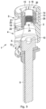
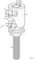
- einen Toilettensitzbefestiger gemäß der Erfindung in perspektivischer Darstellung;
- Figur 13
- einen Achsschnitt des Toilettensitzbefestigers aus
Figur 12 ; - Figur 14
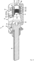
- einen Achsschnitt einer Mutter des Toilettensitzbefestigers aus
Figuren 12 und13 ; und - Figur 15
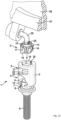
- den Toilettensitzbefestiger aus
Figuren 12 und13 mit einem Scharnier, einem Sitzring und einem Deckel für eine Toilette gemäß der Erfindung. -
Fig. 1 zeigt eine Mutter nach einem erfindungsgemäßen Ausführungsbeispiel, die zum Befestigen eines Toilettensitzes und/oder Toilettendeckels ausgebildet ist. Es versteht sich, dass die Mutter nur mit einem Toilettensitz oder nur mit einem Toilettendeckel verwendet werden kann. Üblicherweise bilden der Toilettensitz und der Toilettendeckel eine Einheit. Der Toilettensitz und/oder Toilettendeckel werden nachstehend als Toilettensitzeinheit bezeichnet. - Die Toilettensitzeinheit und die Mutter bilden eine verkehrsfähige Verkaufseinheit, die zusammen im Handel angeboten werden. Dementsprechend werden die Toilettensitzeinheit und die Mutter als Kombination offenbart. Der Verbinder gemäß
Fig. 5 wird üblicherweise im Zusammenhang mit einem Wandbefestigungssystem für eine Toilettenschüssel angeboten. Für die Endmontage wird die Mutter und die Toilettensitzeinheit mit dem Verbinder bzw. dem Wandbefestigungssystem zusammengebracht. - Nachstehend bezeichnen dieselben Bezugszeichen gleiche oder ähnliche Bauteile. Orts- und Richtungsangaben wie unten, oben, vertikal oder horizontal sind, wenn nichts anderes explizit angegeben ist, auf den Einbauzustand der Toilettenschüssel bezogen.
- In den
Figuren 1 bis 7 ist ein erstes Ausführungsbeispiel der Mutter 3 und des Verbinders 2 dargestellt. DieFiguren 8 bis 11 betreffen ein zweites Ausführungsbeispiel, bei dem sich das Außenprofil 30 der Mutter 3 bzw. das Innenprofil 31 des Verbinders 2 vom ersten Ausführungsbeispiel unterscheiden. - Beide Ausführungsbeispiele beruhen auf demselben Grundprinzip, wonach die Mutter 3 aufgrund des angepassten Außenprofils 30 in den Verbinder 2 von oben eingeführt und im Verbinder 2 begrenzt gedreht werden kann. Die Mutter 3 weist ein Gewinde 26 auf, das in einem Kunststoffkörper 14 angeordnet und gehalten ist. Das Gewinde 26 wird mit dem Scharnier der Toilettensitzeinheit verbunden (siehe
Fig. 11 ). Konkret wird ein Scharnierelement, insbesondere ein Scharnierbolzen in das Gewinde 26 eingeschraubt. - Nachstehend wird der Verbinder 2 näher beschrieben.
- Der Verbinder 2 gemäß
Fig. 5 weist einen ersten (unteren) Aufnahmeraum 4 für den Kopf 8 einer Befestigungsschraube 9 auf, die beispielsweise inFig. 8 dargestellt ist. Die Schraube 9 dient dazu, den Verbinder 2 mit einem Gegenstück des Wandbefestigungssystems (nicht dargestellt) zu verbinden. Der Verbinder 2 weist einen zweiten (oberen) Aufnahmeraum 5 auf, in den die Mutter 3 gemäßFig. 1 bei der Montage eingeführt wird. - Die beiden Aufnahmeräume 4, 5 und die Einführöffnung 20 sind koaxial in Längsrichtung des Verbinders 2 angeordnet. Die beiden Aufnahmeräume 4, 5 sind durch einen Boden 23, der auch als Zwischenwand bezeichnet werden kann, voneinander getrennt. Dies ist in
Fig. 5 sowie bei dem zweiten Ausführungsbeispiel gemäßFig. 9 gut zu erkennen. Im Boden 23 ist eine Mittelöffnung 24 ausgebildet, die koaxial zur Einführöffnung 20 ausgebildet ist und dazu dient, den Zugang für einen Inbusschlüssel zu schaffen, mit dem die Schraube 9 angezogen werden kann. Diese Anordnung ist in denFiguren 8 ,9 dargestellt. Der zweite, obere Aufnahmeraum 5 ist nach außen durch eine Stirnwand 19 begrenzt, die sich parallel zum Boden 23 erstreckt. In der Stirnwand 19 ist die Einführöffnung 20 und das Innenprofil 31 ausgebildet. - Der erste, untere Aufnahmeraum 4 ist bei beiden Ausführungsbeispielen im Wesentlichen identisch ausgebildet. Der Aufnahmeraum 4 wird durch eine untere Stirnwand 6 begrenzt, die sich parallel zum Boden 23 erstreckt und und einen Schlitz 7 zur Aufnahme des Schraubenkopfes 8 aufweist (siehe
Fig. 8 ). Der Schlitz 7 wird durch 2 Schnappnasen 12 begrenzt, die den Kopf 8 im Aufnahmeraum 4 halten. - Das Innenprofil 31 bildet den Innenumfang der Einführöffnung 20. Das Innenprofil 31 umfasst mehrere Montageöffnungen 39, die zwischen Haltevorsprünge 40 ausgebildet sind. Die Haltevorsprünge 40 und die Montageöffnungen 39 sind abwechselnd auf dem Umfang verteilt angeordnet. Die Haltevorsprünge 40 sind rippenförmig ausgebildet. Die Form der Haltevorsprünge 40 entspricht im Wesentlichen der Form der nachstehend näher erläuterten Rippen 16, 16a, 16b der Mutter 3.
- Das Innenprofil 31 weist ferner eine Einführkante 35 auf, wobei eine weitere Einführkante 35 diametral gegenüber angeordnet ist. Die beiden Einführkanten 35 sind symmetrisch. Die Einführkanten 35 sind jeweils breiter, als die Haltevorsprünge 40 bzw. die Montageöffnungen 39. Die Einführkanten 35 wirken mit den Rastfedern 17 der Mutter 3 zusammen.
- Die Haltevorsprünge 40 und in die Einführkante 35 bilden jeweils Hinterscheidungen 21, wie in
Fig. 6 dargestellt. Die Hinterschneidungen 21 werden im Gebrauch vom Außenprofil 30 der Mutter 3 hintergriffen und blockieren so eine axiale Bewegung der Mutter, die dadurch im Aufnahmeraum 5 fest gehalten wird. - Im Boden 23 ist eine Ausnehmung 22 ausgebildet, die sich radial erstreckt. Die Ausnehmung 22 kann auch als Drehsicherungsnut bezeichnet werden. Anschlagfläche 41 begrenzt die Ausnehmung 22 und dient im Gebrauch als Anschlag und somit als Verdrehsicherung für die Mutter 3. Die Breite der Ausnehmung 22, d.h. der Abstand zwischen den gegenüberliegenden Anschlagflächen 41 ist so bemessen, dass eine begrenzte Drehung der Mutter 3 im Aufnahmeraum möglich ist.
- Nachstehend wird die Mutter 3 im Detail erläutert.
- Das Außenprofil 30 der Mutter 3 erstreckt sich in Umfangsrichtung um die Mutter 3 sowie in axialer und radialer Richtung bezogen auf die Mutter 3. Das Außenprofil 30 der Mutter 3 und das Innenprofil 31 des Verbinders 2 sind aneinander angepasst. Konkret ist das Außenprofil 30 so angepasst, dass die Mutter 3 in axialer Richtung, d.h. entlang der Mittelachse des Verbinders 2 durch die Einführöffnung 20 in den Aufnahmeraum 5 eingeführt werden kann. Die dafür vorgesehene Position der Mutter 3 wird als erste Montageposition bezeichnet. Das Außenprofil 30 ist weiterhin so angepasst, dass die Mutter 3 im Aufnahmeraum 5 in Umfangsrichtung der Mutter 3 gedreht werden kann. Durch die Drehung hintergreift das Außenprofil 30 zumindest teilweise das Innenprofil 31. Diese Position der Mutter 3 wird als zweite Halteposition bezeichnet. In der Halteposition bildet das Außenprofil 30 eine in Längsrichtung des Verbinders 2 wirkende axiale Zugsicherung, durch die die Mutter 3 im Verbinder 2 fest gehalten wird.
- Wie in
Fig. 1 zu erkennen, weist das Außenprofil 30 mehrere Rippen 16, 16a, 16b auf, die auf dem Umfang der Mutter 3 verteilt angeordnet sind. Die Rippen 16, 16a, 16b stehen radial von der Mutter 3 nach außen ab und erstrecken sich in axialer Richtung, d.h. parallel zur Längsachse der Mutter 3. Die Längsachse der Mutter 3 kann auch als Mittelachse bezeichnet werden. Konkret weist die Mutter 3 zehn Rippen 16, 16a, 16b auf, die symmetrisch auf dem Umfang der Mutter 3 verteilt angeordnet sind. - Das Innenprofil 31 des Verbinders 2 weist eine entsprechende Anzahl von Montageöffnungen 39 (konkret zehn Montageöffnungen 39) auf, die auf dem Umfang der Einführöffnung 20 verteilt angeordnet sind. Die Dimensionen und Positionen der Rippen 16, 16a, 16b sind an die Montageöffnungen 39 angepasst.
- Es ist möglich, dass die Mutter 3 weniger als zehn Rippen aufweist. Generell gilt, dass die maximale Anzahl der Rippen 16, 16a, 16b der Mutter 3 der Anzahl der Montageöffnungen 39 des Verbinders 2 entspricht. Die Mutter 3 kann weniger Rippen 16, 16a, 16b als Montageöffnungen 39 des Verbinders 2 aufweisen.
- Die oberen Stirnflächen der Rippen 16, 16a, 16b sind als Anschlagflächen 37 ausgebildet, die in der Halteposition am Innenprofil 31 des Verbinders, konkret an der Unterseite der Haltevorsprünge 40 anliegen und eine axiale Bewegung der Mutter 3 blockieren. Die Anschlagflächen 37 sind in ein und derselben Ebene angeordnet, die sich senkrecht zur Längsachse der Mutter 30 erstreckt. Dadurch wird erreicht, dass die Rippen 16, 16a, 16b durch die Drehbewegung unter die Haltevorsprünge 40 des Innenprofils 31 bewegt werden können.
- Wie in
Fig. 2 dargestellt, sind die unteren Stirnflächen der Rippen 16, 16a, 16b ebenfalls in ein und derselben Ebene angeordnet, die senkrecht zur Mittelachse bzw. Längsachse der Mutter 3 verläuft. Die Unterkante 33 ist in dieser Ebene angeordnet. Die Mutter 3 liegt auf der Unterseite der Rippen 16, 16b im Aufnahmeraum 5 auf. - Die Rippen 16, 16a weisen eine erste Rippe 16a auf, die als Verdrehsicherung ausgebildet ist. Im Unterschied zu den zweiten Rippen 16b, die im Wesentlichen dieselbe Höhe aufweisen, steht die erste Rippe 16a nach unten vor und bildet einen Fortsatz oder Vorsprung 18 (Verdrehsicherung). Der Vorsprung 18 steht in axialer Richtung über die Unterkante 33 der Mutter 3 vor, wie in
Fig. 1 zu erkennen. Dasselbe gilt für das zweite Ausführungsbeispiel, wieFig. 8 dargestellt. Im Aufnahmeraum 5 greift der Vorsprung 18 in die zugehörige Ausnehmung 22 im Boden 23 des Verbinders 2 ein. Die Ausnehmung 22 kann auch als Drehsicherungsnut bezeichnet werden. Der Eingriffszustand ist in denFiguren 8 ,9 anhand des zweiten Ausführungsbeispiels dargestellt. - Bei dem ersten Ausführungsbeispiel gemäß
Fig. 1 sind zwei erste Rippen 16a als Verdrehsicherung ausgebildet, die diametral gegenüber angeordnet sind. Die Ausnehmung 22 im Boden 23 des Verbinders 2 ist entsprechend ausgebildet und erstreckt sich auf beiden Seiten der Mittelöffnung 24. - Die Mutter 3 weist diametral gegenüber angeordnete Rastfedern 17, insbesondere zwei Rastfedern 17 auf. Die Rastfedern 17 sind an der Unterkante 33 der Mutter 3 mit einem Fuß 38 an der Mutter 3 befestigt und stehen schräg nach oben entgegen der Montagerichtung vor. Das freie Ende 34 der Rastfedern 17 ist radial weiter außen angeordnet als der Fuß 38 und bildet die maximale Radiallage der Rastfeder 17. Die Rastfeder 17 ist in radialer Richtung bewegbar.
- Bei der Montage werden die Rastfedern 17 durch die Einführkante 35 an der Einführöffnung 20 des Verbinders 2 radial nach innen gedrückt. Wenn die Mutter 3 die Einführöffnung 20 vollständig passiert hat, schnappen die Rastfedern 17 in die in
Fig. 3 dargestellte Ruhelage zurück, sodass sich die freien Enden 34 radial nach außen bewegen. In dieser Halteposition hintergreifen die Rastfedern 17 das Innenprofil 31 und liegen an der Unterseite des Innenprofils 31 im Bereich der Einführkanten 35 an. Die Mutter 3 ist axial gesichert und kann bei der Montage nicht mehr ungewollt aus dem Verbinder 2 rutschen. - Die Anordnung der Rastfedern 17 sowie der zugehörigen Einführkanten 35 hat den weiteren Vorteil, dass die Mutter 3 in einer vorgegebenen Position in die Einführöffnung 20 eingeführt wird. Dies liegt daran, dass die Einführkante 30 breiter ist als die Montageöffnungen 39. Dadurch wird erreicht, dass die beiden ersten Rippen 16a (Verdrehsicherung) korrekt ausgerichtet sind und in die zugehörigen Ausnehmungen 22 im Boden 23 eingreifen. Es versteht sich, dass die Mutter 3 eine einzige erste Rippe 16a als Verdrehsicherung aufweisen kann.
- Wie in
Fig. 1 dargestellt, weist die Mutter einen Kragen 15 auf, der ringförmig nach oben über die Rippen 16, 16a, 16b vorsteht. Der Kragen ist koaxial zum Gewinde 26 ausgebildet (Fig. 2 ). Der Außendurchmesser des Kragens 15 ist so bemessen, dass dieser mit Spiel in der Einführöffnung 20, d.h. zwischen den Haltevorsprünge 40 des Verbinders 2 angeordnet werden kann. - Die Rippen 16, 16a, 16b sind wie folgt dimensioniert und positioniert (s.
Figuren 2, 3 ,4 ). Bis auf die Höhe sind die Rippen 16, 16a, 16b entsprechend dimensioniert. Die ersten Rippen 16a sind als Verdrehsicherung höher als die zweiten Rippen 16b. Die Rastfedern 17 sind ebenfalls entsprechend dimensioniert. - Die maximale Höhe A einer Rippe 16, konkret einer zweiten Rippe 16b (ohne Verdrehsicherung) beträgt A = ca. 11 mm, insbesondere A = 10,9 mm. Die Höhe A einer Rippe 16, 16b kann kleiner sein, bspw. 10,8 mm, 10,7 mm usw..
- Der maximale Abstand B zwischen dem freien Ende 34 der Rastfeder 17 und einer imaginären Verlängerung der Unterkante 33 beträgt B = ca. 11 mm, insbesondere B = 10,9 mm. Höhe B einer Rippe 16, 16b kann kleiner sein, bspw. 10,8 mm, 10,7 mm usw..
- Die maximale Breite C einer Rippe 16, 16a, 16b beträgt C = ca. 2,8 mm. Die maximale Breite liegt an der Außenkante der Rippe 16 vor. Wie vorstehend beschrieben kann die maximale Breite C kleiner als 2,8 mm sein.
- Der maximale Außendurchmesser D des Außenprofils 30, d.h. der Abstand zwischen den Außenkanten zweier diametral gegenüber angeordneter Rippen 16 beträgt D = ca. 20,5 mm. Kleinere Abstände sind möglich. Die Untergrenze des Abstandes D beträgt D = ca. 20,7 mm.
- Der Öffnungswinkel E der Rastfedern 17 in der Ruhelage beträgt E = ca. 12°
Der Winkel zwischen zwei unmittelbar angrenzender Rippen 16, 16a, 16b beträgt G1 = ca. 30°. Im Bereich der Rastfedern 17 beträgt der Winkel G2 zwischen zwei Rippen 16 G2 = ca. 60°. Mit anderen Worten ersetzt eine Rastfeder 17 eine Rippe 16. - Die Rippen 16, 16a, 16b verbreitern sich mit zunehmendem Abstand von der Mittelachse der Mutter 3. Der Winkel F zwischen den Seitenflächen 32 einer Rippe 16 beträgt maximal F = ca. 16°. Konkret beträgt der Winkel F = 15°. Kleinere Winkel F sind möglich.
- Wie
Fig. 7 zu entnehmen, korreliert das Außenprofil 30 der Mutter 3 mit dem Innenprofil 31 des Verbinders 2. - So entspricht die Anzahl der Rippen 16, 16a, 16b der Mutter 3 der Anzahl der Montageöffnungen 39 bzw. der Haltevorsprünge 40 des Verbinders 2. Die Winkel g1, g2 zwischen angrenzenden Montageöffnungen 39 entsprechen den Winkeln G1, G2 zwischen angrenzenden Rippen 16, 16a, 16b. Die Winkel g1, g2 betragen g1 = 30° und g2 = 60° wobei der Winkel g2 Montageöffnungen 39 betrifft, zwischen denen die Einführkante 30 ausgebildet ist. Der Winkel f zwischen den Seitenflächen 42 einer Montageöffnung 40 beträgt f = ca. 16°. Der Abstand c zwischen den Seitenflächen 42 einer Montageöffnung 40 beträgt c = ca. 2,8 mm. Der größere Innendurchmesser d1 zwischen zwei diametral gegenüber angeordneten Montageöffnungen 39 beträgt die d1 = ca. 20,7 mm. Der kleinere Innendurchmesser d2 des Innenprofils 31 beispielsweise zwischen den Einführkanten 35 oder zwischen zwei diametral gegenüber angeordneten Haltevorsprünge 40 beträgt d2 = ca. 17 mm. Wie in
Fig. 6 gezeigt, beträgt die Höhe a des Aufnahmeraums 5, konkret der Abstand zwischen dem Boden 23 neben der Ausnehmung 22 und der Unterseite der Haltevorsprünge bzw. allgemein der Hinterschneidung 21 a = ca. 11 mm. - Das zweite Ausführungsbeispiel im 8 bis 11 unterscheidet sich vom ersten Ausführungsbeispiel gemäß
Figuren 1 bis 7 einerseits dadurch, dass das Außenprofil 30 der Mutter 3 Rippen und Rastfedern aufweist, die auf dem Umfang der Mutter 3 abwechselnd angeordnet sind. Das Innenprofil 31 der Einführöffnung 20 des Verbinders 2 ist entsprechend ausgebildet und weist mehrere Einführkanten und Montageöffnungen abwechselnd verteilt auf dem Umfang auf. Das Grundprinzip, wonach die Mutter 3 von oben in den Aufnahmeraum 5 des Verbinders 2 eingeführt werden kann (erste Montageposition) entspricht dem Grundprinzip der Mutter gemäßFig. 1 . Dasselbe gilt für die Bewegung der Mutter 3 im Aufnahmeraum 5, die durch eine Drehung in die Halteposition überführt werden kann. Dies ist bei dem Ausführungsbeispiel gemäßFiguren 8 bis 11 entsprechend möglich. - Ein weiterer Unterschied besteht darin, dass die Wandung des Aufnahmeraums 5 im Bereich der Ausnehmung 22 bei dem zweiten Ausführungsbeispiel weiter als bei dem ersten Ausführungsbeispiel ausgeschnitten ist. Im Übrigen stimmen die beiden Ausführungsbeispiele überein.
- Die Montage ist anhand der Darstellung gemäß
Fig. 11 verdeutlicht, wobei in der Praxis die Mutter 3 zumeist mit einem Scharnierbolzen verschraubt ist, der wiederum mit dem Scharniergelenk der Toilettensitzeinheit verbunden ist, beispielsweise durch einen Rastverschluss. Das Prinzip ist dasselbe. - Der Verbinder 2 mit der Schraube 9 im unteren Aufnahmeraum 4 wird mit einem nicht dargestellten Wandbefestigungssystem verschraubt, wobei die Schraube 9 von oben mit einem Sechskantschlüssel durch die Einführöffnung 20 und die Mittelöffnung 24 eingeschraubt wird. Damit ist der Verbinder 2 in der Toilettenschüssel montiert.
- Daraufhin wird von oben, wie in
Fig. 11 dargestellt, die Mutter 3 mit dem Scharnier bzw. Scharnierelement 29 in der Montageposition in den Verbinder 2 eingeführt, wie durch den Richtungspfeil dargestellt. In der Montageposition sind das Außenprofil 30 der Mutter und das Innenprofil 31 der Einführöffnung 20 bzw. des Verbinders 2 so ausgerichtet, dass die Mutter 3 durch die Einführöffnung 20 passt. Konkret fluchten die Rippen 16, 16a, 16b mit den Montageöffnungen 39, so dass die Rippen 16, 16a, 16b durch die jeweilige Montageöffnungen 39 hindurch bewegt werden können. Falls die Mutter 3, wie in beiden Ausführungsbeispiele gezeigt, mit Rastfedern 17 ausgestattet sind, sind diese ebenfalls mit dem zugehörigen Innenprofil 31 ausgerichtet, konkret mit den Einführkanten 35. Beim ersten Ausführungsbeispiel hat dies den Vorteil, dass die erste Rippe 16a mit der Verdrehsicherung korrekt positioniert ist. - Im Aufnahmeraum 5 greift der Vorsprung 18 der ersten Rippe 16a in die Ausnehmung 22 im Boden 23 des oberen Aufnahmeraums. Die übrigen zweiten Rippen 16b liegen auf dem Boden 23 neben der Ausnehmung 22 auf. Die Anschlagfläche 37 der Rippen 16, 16a, 16b ist geringfügig tiefer angeordnet, als die Unterseite bzw. Hinterschneidung 21 des Innenprofils 31.
- Die Mutter 3 bzw. das Gewinde 26 der Mutter 3 wird dann mit dem Scharnierelement 23, insbesondere dem Scharnierbolzen verbunden. Es ist auch möglich, wie in
Fig. 11 dargestellt, zuerst die Mutter 3 mit dem Scharnierbolzen bzw. Scharnierelement 29 zu verbinden und dann die Mutter 3 in den Verbinder 2 einzustecken. - Durch das über den Scharnierbolzen eingeleitete Drehmoment wird die Mutter 3 in Umfangsrichtung im Aufnahmeraum gedreht und zwar so weit, bis der Vorsprung 18 an einer der Anschlagflächen 41 der Ausnehmung 22 anschlägt. Dadurch werden zwei Wirkungen erreicht. Einerseits werden die Rippen 16, 16a, 16b durch die Drehbewegung der Mutter 3 unter die Haltevorsprünge 40 der Stirnwand 19 bewegt. Damit ist die Mutter 3 im Aufnahmeraum 5 axial gesichert. Die Drehbewegung der Mutter 3 wird dann durch die Anschlagfläche 41 blockiert, sodass der Scharnierbolzen weiter in die Mutter 3 eingeschraubt und diese mit dem Verbinder verspannt wird. Dabei kann die Toilettensitzeinheit justiert werden, bevor der Scharnierbolzen fest angezogen wird.
- Auf diese Weise wird das Scharnier der Toilettensitzeinheit perfekt mit der Schüssel verbunden, wobei die Montage einfach und schnell erfolgt.
- Der in
Figuren 12 und13 gezeigte Toilettensitzbefestiger 1 dient einer Befestigung eines Sitzrings und/oder eines Deckels auf einer nicht gezeichneten Toilette. Der Toilettensitzbefestiger 1 weist einen Verbinder 2 und eine Mutter 3 auf. Im Ausführungsbeispiel ist der Verbinder 2 ein zylinderförmiges Kunststoffteil mit zwei seitlich und an Stirnseiten des Verbinders 2 offenen Höhlungen 4, 5. An einem Stirnende, das nachfolgend als unteres Stirnende bezeichnet wird, weist der Verbinder 2 eine nach innen stehende Stirnwand 6 mit einem Schlitz 7 auf, der auf der Seite offen ist, an der auch die zugeordnete Höhlung 4 offen ist, welche nachfolgend als untere Höhlung 4 bezeichnet wird. Radial von einer Seite ist ein spezieller Schraubenkopf 8 einer Schraube 9 in den Schlitz 7 einbringbar. Mit "spezieller Schraubenkopf" ist gemeint, dass der Schraubenkopf 8 zylinderförmig ist und einen Innensechskant 10 in einer Stirnseite als Werkzeugsitz zu einem Drehen der Schraube 9 mit einem nicht gezeichneten Inbusschlüssel und zwei Parallelnuten 11 am Umfang aufweist. Die Parallelnuten 11 sind einander gegenüber angeordnet und weisen zueinander parallele Nutgründe auf. Die Stirnwand 6 des Verbinders 2 greift in die Parallelnuten 11 des Schraubenkopfs 8 ein, so dass die Schraube 9 gleichachsig, dreh- und axialfest mit dem Verbinder 2 verbunden ist. Der Schraubenkopf 8 mit den Parallelnuten 11 und die Stirnwand 6 des Verbinders 2 mit dem Schlitz 7 können auch als Einrichtung zum Verbinden der Schraube 9 mit dem Verbinder 2 aufgefasst werden. An einer Öffnung des Schlitzes 7 weist die Stirnwand 6 des Verbinders 2 nach innen stehende Schnappnasen 12 auf, die den Schraubenkopf 8 im Schlitz 7 halten. Mit der Schraube 9 lässt sich der Verbinder 2 an der nicht gezeichneten Toilette befestigen. - Die in
Figur 14 in einem Achsschnitt als Einzelteil gezeichnete Mutter 3 weist eine herkömmliche Sechskantmutter 13 aus Metall auf, die mit einem Kunststoffkörper 14 umspritzt ist. Der Kunststoffkörper 14 ist Teil der Mutter 3 und weist einen zur Sechskantmutter 13 koaxialen, rohrförmigen, axial kurzen Kragen 15 und sternförmig nach außen stehende Rippen 16 auf. Außerdem stehen Federzungen, die nachfolgend als Rastelemente 17 bezeichnet werden, in einem spitzen Winkel zu einer Achse der Mutter 3 schräg in Richtung des Kragens 15 nach außen von der Mutter 3 ab. Auf einer dem Kragen 15 gegenüberliegenden Stirnseite der Mutter 3 gehen die Federzungen einstückig in den Kunststoffkörper 14 der Mutter 3 über. Durch eine 5 Elastizität des Kunststoffs federn in Richtung des Krages 15 schräg nach außen weisende, freie Enden der die Rastelemente 17 bildenden Federzungen in radialer Richtung der Mutter 3. An der dem Kragen 15 gegenüberliegenden Stirnseite weist der Kunststoffkörper 14 der Mutter 3 zwei Drehsicherungsnasen 18 in einer Axialebene der Mutter 3 auf. - An einem der Stirnwand 6 mit dem Schlitz 7 gegenüberliegenden Stirnende, das hier als oberes Stirnende bezeichnet wird, weist der Verbinder 2 eine lochscheibenförmige Stirnwand 19 mit einem Mittelloch auf, das ein zu den Rippen 16 der Mutter 3 komplementäres Vielnutprofil aufweist. Das Mittelloch der Stirnwand 19 am oberen Stirnende des Verbinders 2 wird nachfolgend als Öffnung 20 der angrenzenden Höhlung 5 des Verbinders 2 bezeichnet werden, wobei diese Höhlung 5 nachfolgend als obere Höhlung 5 bezeichnet werden wird. Die Öffnung 20 der oberen Höhlung 5 korrespondiert geometrisch mit der Mutter 3. Durch die Öffnung 20 kann die Mutter 3 axial zur Schraube 9 in die obere Höhlung 5 des Verbinders 2 eingebracht werden, wobei die Rastelemente 17 an einer der oberen Höhlung 5 zugewandten Unterseite der Stirnwand 19 einrasten, so dass die Mutter 3 axialfest in der Höhlung 5 gehalten ist. Die Unterseite der Stirnwand 19 bildet eine Hinterschneidung 21, welche die Rastelemente 17 hintergreifen. Der Verbinder 2 des Toilettensitzbefestigers 1 verbindet die Mutter 3 gleichachsig und axialfest mit der Schraube 9. "Axialfest" bedeutet eine zug- und druckfeste Verbindung der Mutter 3 mit der Schraube 9. Die Rastelemente 17 und die Stirnwand 19, die die Rasteelemente 17 hintergreifen, bilden eine Rasteinrichtung 17, 19, die beim Einbringen der Mutter 3 in die obere Höhlung 5 des Verbinders 2 einrastet und die Mutter 3 in der oberen Höhlung 5 hält.
- Durch die seitliche Öffnung der oberen Höhlung 5 könnte eine anders geformte Mutter auch seitlich in die obere Höhlung 5 eingebracht werden (nicht dargestellt). In einer alternativen Ausführungsform (nicht dargestellt) weist die obere Höhlung 5 keine seitliche Öffnung auf, oder die seitliche Öffnung ist so klein, dass keine Mutter seitlich einbringbar ist.
- Durch die Öffnung 20 am oberen Stirnende des Verbinders 2 und ein Mittelloch 24 in einer Zwischenwand 23 zwischen den beiden Höhlungen 4, 5 des Verbinders 2 lässt sich ein nicht dargestellter Inbusschlüssel zu einem Drehen und Festziehen der Schraube 9 am Innensechskant 10 ihres Schraubenkopfs 3 ansetzen.
- Die Rippen 16 sind so an der Mutter 3 angeordnet und geformt, dass sich die Mutter 3 nur in einer bestimmten und in einer dazu um 180° gedrehten Winkelstellung durch das komplementäre Vielnutprofil der Öffnung 20 in die obere Höhlung 5 des Verbinders 2 einbringen lässt. In dieser Winkelstellung befinden sich die beiden Drehsicherungsnasen 18 in derselben Axialebene wie eine Drehsicherungsnut 22 in der Zwischenwand 23 zwischen den beiden Höhlungen 4, 5 des Verbinders 2. Dadurch gelangen die Drehsicherungsnasen 18 beim Einbringen der Mutter 3 durch die Öffnung 20 in der Stirnwand 19 im oberen Stirnende des Verbinders 2 in die obere Höhlung 5 in die Drehsicherungsnut 22 in der Zwischenwand 23, so dass die Mutter 3 durch Formschluss drehfest in der oberen Höhlung 5 des Verbinders 2 aufgenommen ist. Andere Drehsicherungen der Mutter 3 in der oberen Höhlung 5 des Verbinders 2 sind nicht ausgeschlossen. Der Verbinder 2 verbindet die Mutter 3 drehfest mit der Schraube 9.
- Der Kragen 15 der Mutter 3 ragt in die Öffnung 20 der Stirnwand 19, wenn die Mutter 3 in die obere Höhlung 5 des Verbinders 2 eingebracht ist. Dabei weist der Kragen 15 Spiel in der Öffnung 20 auf, so dass die Mutter 3 radial beweglich in der oberen Höhlung des Verbinders 2 aufgenommen ist. Dadurch lässt sich ein Sitzring und/oder Deckel, der mit dem Verbinder 2 an einer Toilette befestigt wird, an der Toilette ausrichten.
- In
Figur 15 ist ein rechtwinklig abgewinkelter Bolzen mit einem Gewinde 25 an einem Schenkel in ein Mutterngewinde 26 der Mutter 3 geschraubt. Auf einem anderen Schenkel des abgewinkelten Bolzens sind ein Sitzring 27 und ein Deckel 28 schwenkbar gelagert. Der abgewinkelte Bolzen bildet ein Scharnier oder Scharnierelement 29 für den Sitzring 27 und den Deckel 28, über das der Sitzring 27 und der Deckel 28 mittels der Mutter 3 am Verbinder 2 des Toilettensitzbefestigers 1 und über den Verbinder 2 und die Schraube 9 an der nicht gezeichneten Toilette befestigbar sind. Die Befestigung des Scharnierelements 29 mit dem Sitzring 27 und dem Deckel 28 erfolgt durch Einbringen und Einrasten der Mutter 3, in die das Scharnierelement 29 geschraubt ist, durch die Öffnung 20 in die obere Höhlung 5 des Verbinders 2. Grundsätzlich lässt sich die Mutter 3 auch ohne das Scharnierelement 29 durch die Öffnung 20 in die obere Höhlung 5 des Verbinders 2 einbringen und einrasten. -
- 1
- Befestigungssystem
- 2
- Verbinder
- 3
- Mutter
- 4
- Aufnahmeraum für den Schraubenkopf
- 5
- Aufnahmeraum für die Mutter
- 6
- Stirnwand (Aufnahmeraum für den Schraubenkopf)
- 7
- Schlitz
- 8
- Schraubenkopf
- 9
- Schraube
- 10
- Innensechskant
- 11
- Parallelnut
- 12
- Schnappnase
- 13
- Sechskantmutter
- 14
- Kunststoffkörper
- 15
- Kragen
- 16
- Rippe
- 16a
- erste Rippe (Verdrehsicherung)
- 16b
- zweite Rippe (Zugsicherung)
- 17
- Rastfeder
- 18
- Vorsprung (Drehsicherungsnase)
- 19
- Stirnwand (Aufnahmeraum für die Mutter)
- 20
- Einführöffnung
- 21
- Hinterschneidung
- 22
- Ausnehmung (Drehsicherungsnut)
- 23
- Boden (Zwischenwand)
- 24
- Mittelöffnung
- 25
- Gewinde
- 26
- Mutterngewinde
- 27
- Sitzring
- 28
- Deckel
- 29
- Scharnierelement
- 30
- Außenprofil
- 31
- Innenprofil
- 32
- Seitenflächen (Rippen)
- 33
- Unterkante
- 34
- freies Ende
- 35
- Einführkante
- 36
- frei
- 37
- Anschlagfläche der Rippe (Zugsicherung)
- 38
- Fuß
- 39
- Montageöffnungen
- 40
- Haltevorsprünge
- 41
- Anschlagfläche der Ausnehmung (Verdrehsicherung)
- 42
- Seitenflächen (Montageöffnungen)
-
- A
- maximale Höhe einer Rippe
- B
- maximaler Abstand
- C
- maximale Breite einer Rippe
- D
- maximaler Durchmesser des Außenprofils
- E
- Winkel der Rastfeder in der Ruhelage
- F
- Winkel der Seitenflächen einer Rippe
- G1
- Winkel zwischen angrenzenden Rippen
- G2
- Winkel zwischen angrenzenden Rippen
-
- a
- Innenhöhe des Aufnahmeraums der Mutter
- b
- frei
- c
- Breite einer Montageöffnung
- d1
- Außendurchmesser des Innenprofils
- d2
- Innendurchmesser des Innenprofils
- f
- Winkel der Seitenflächen einer Montageöffnung
- g1
- Winkel zwischen angrenzenden Montageöffnungen
- g2
- Winkel zwischen angrenzenden Montageöffnungen
-
- 1
- Toilettensitzbefestiger
- 2
- Verbinder
- 3
- Mutter
- 4
- untere Höhlung (unterer Aufnahmeraum)
- 5
- obere Höhlung (oberer Aufnahmeraum)
- 6
- Stirnwand
- 7
- Schlitz
- 8
- Schraubenkopf
- 9
- Schraube
- 10
- Innensechskant
- 11
- Parallelnut
- 12
- Schnappnase
- 13
- Sechskantmutter
- 14
- Kunststoffkörper
- 15
- Kragen
- 16
- Rippe
- 17
- Rastelement
- 18
- Drehsicherungsnase (Vorsprung)
- 19
- Stirnwand
- 20
- Öffnung
- 21
- Hinterschneidung
- 22
- Drehsicherungsnut (Ausnehmung)
- 23
- Zwischenwand (Boden)
- 24
- Mittelloch
- 25
- Gewinde
- 26
- Mutterngewinde (Gewinde der Mutter)
- 27
- Sitzring
- 28
- Deckel
- 29
- Scharnierelement
- 20
- Öffnung
- 21
- Hinterschneidung
- 22
- Drehsicherungsnut (Ausnehmung)
- 23
- Zwischenwand (Boden)
- 24
- Mittelloch
- 25
- Gewinde
- 26
- Mutterngewinde (Gewinde der Mutter)
- 27
- Sitzring
- 28
- Deckel
- 29
- Scharnierelement
Claims (7)
- Befestigungssystem (1) zum Befestigen eines Toilettensitzes und/oder Toilettendeckels an einer Toilettenschüssel, das einen zylinderförmigen Verbinder (2) und eine Mutter (3) aufweist, wobei der zylinderförmige Verbinder (2) mit der Toilettenschüssel verbindbar ist und einen Aufnahmeraum (5) für die Mutter (3) bildet sowie ferner ein Innenprofil (31) aufweist, das im Bereich einer Einführöffnung (20) für die Mutter (3) in den Aufnahmeraum (5) rippenförmig ausgebildet ist und weist diametral gegenüber angeordnete Einführkanten (35) auf, die jede eine Hinterschneidung (21) für eine Rastfeder (17) der Mutter (3) bildet, wobei die Mutter (3) in den Aufnahmeraum (5) einführbar ist und ein Gewinde (26) aufweist, das mit einem Scharnierelement (29) des Toilettensitzes und/oder Toilettendeckels verbindbar ist, wobei ein Außenprofil (30) der Mutter (3), das mit dem Innenprofil (31) des Verbinders (2) korreliert, mehrere axiale Rippen (16, 16a, 16b), umfassend erste und zweite Rippen, aufweist, die auf dem Umfang der Mutter (3) verteilt angeordnet und mit dem rippenförmigen Innenprofil (31) des Verbinders (2) so ausgerichtet sind, dass die Mutter (3) in axialer Richtung, d.h. entlang der Mittelachse des Verbinders (2) durch die Einführöffnung (20) in den Aufnahmeraum (5) eingeführt werden kann und die Mutter (3) diametral gegenüber angeordnete Rastfedern (17) aufweist, die zusammen wirken mit den Einführkanten (35) und die radial nach innen und radial nach außen bewegbar sind, und wobei wenigstens eine zweite Rippe (16b) als axiale Zugsicherung zur Fixierung der Mutter (3) im Aufnahmeraum (5) in Längsrichtung des Verbinders (2) ausgebildet ist, die bei einer Verdrehung des Außenprofils (30) der Mutter (3) aus eine Montageposition in eine Halteposition das rippenförmige Innenprofil (31) des Verbinders (2) zumindest teilweise hintergreift, und wobei das Außenprofil (30) der Mutter (3) eine oder zwei diametral gegenüber angeordnete erste Rippe(n) (16a) mit einem Vorsprung (18) als Verdrehsicherung zur Fixierung der Mutter (3) im Aufnahmeraum (5) in Umfangsrichtung des Verbinders (2) aufweist, wobei der Vorsprung (18) in axialer Richtung über eine Unterkante (33) der Mutter (3) vorsteht und mit einer oder zwei entsprechenden Ausnehmung(en) (22) im Boden (23) des Aufnahmeraums (5) in Eingriff bringbar ist/sind.
- Befestigungssystem nach einem der vorhergehenden Ansprüche,
dadurch gekennzeichnet, dass
die Breite einer Rippe (16, 16a, 16b) zumindest im maximalen Querschnitt höchstens 2,8 mm beträgt. - Befestigungssystem nach einem der vorhergehenden Ansprüche,
dadurch gekennzeichnet, dass
die sich in axialer Richtung erstreckenden Seitenflächen (32) einer Rippe (17) einen Winkel von höchstens 16° bilden. - Befestigungssystem nach einem der vorhergehenden Ansprüche,
dadurch gekennzeichnet, dass
die Rastfeder (17) in der Ruhestellung eine maximale Radiallage einnimmt, wobei der vertikale Abstand zwischen der maximalen Radiallage und einer imaginären Verlängerung der Unterkante (33) der Mutter (3) höchstens 11 mm beträgt. - Befestigungssystem nach Anspruch 4
dadurch gekennzeichnet, dass
die maximale Radiallage durch ein freies Ende (34) der Rastfeder (17) gebildet ist, das radial nach innen und radial nach außen bewegbar ist. - Scharnier für einen Toilettensitz und/oder Toilettendeckel mit einem Befestigungssystem (1) nach einem der Ansprüche 1 bis 5.
- Toilettensitz und/oder Toilettendeckel mit einem Scharnierelement (29) nach Anspruch 6 und einem Befestigungssystem (1) nach einem der Ansprüche 1 bis 5.
Applications Claiming Priority (4)
| Application Number | Priority Date | Filing Date | Title |
|---|---|---|---|
| DE102016124344.2A DE102016124344A1 (de) | 2016-12-14 | 2016-12-14 | Toilettensitzbefestiger, Scharnierelement und Sitzring |
| DE202017102019.3U DE202017102019U1 (de) | 2016-12-14 | 2017-04-05 | Toilettenbefestiger, Scharnierelement und Sitzring |
| DE202017102020.7U DE202017102020U1 (de) | 2016-12-14 | 2017-04-05 | Mutter, Scharnier, Toilettensitz, Verbinder, Befestigungssystem und Anordnung |
| PCT/EP2017/082876 WO2018109104A1 (de) | 2016-12-14 | 2017-12-14 | Mutter, scharnier, toilettensitz, verbinder, befestigungssystem und anordnung |
Publications (2)
| Publication Number | Publication Date |
|---|---|
| EP3554330A1 EP3554330A1 (de) | 2019-10-23 |
| EP3554330B1 true EP3554330B1 (de) | 2024-02-07 |
Family
ID=61866203
Family Applications (1)
| Application Number | Title | Priority Date | Filing Date |
|---|---|---|---|
| EP17817736.6A Active EP3554330B1 (de) | 2016-12-14 | 2017-12-14 | Mutter, scharnier, toilettensitz, verbinder, befestigungssystem und anordnung |
Country Status (3)
| Country | Link |
|---|---|
| EP (1) | EP3554330B1 (de) |
| DE (3) | DE102016124344A1 (de) |
| WO (1) | WO2018109104A1 (de) |
Families Citing this family (1)
| Publication number | Priority date | Publication date | Assignee | Title |
|---|---|---|---|---|
| DE102024119800A1 (de) * | 2024-07-11 | 2026-01-15 | Hamberger Industriewerke Gmbh | Befestigungsstift; Bausatz für WCs |
Citations (1)
| Publication number | Priority date | Publication date | Assignee | Title |
|---|---|---|---|---|
| DE202015008989U1 (de) * | 2015-11-26 | 2016-07-01 | Villeroy & Boch Ag | Befestigungssystem für einen Toilettensitz, Käfig, Käfigmutter und Anordnung |
Family Cites Families (5)
| Publication number | Priority date | Publication date | Assignee | Title |
|---|---|---|---|---|
| JP3319566B2 (ja) * | 1995-03-31 | 2002-09-03 | 株式会社イナックス | 連結用クリップ |
| DE202007017328U1 (de) * | 2007-12-12 | 2008-02-28 | Villeroy & Boch Ag | Vorrichtung zum Befestigen eines wandhängenden Objektes |
| US9127706B2 (en) * | 2012-02-21 | 2015-09-08 | Michael R. Leibfried | One way slip mounting apparatus |
| US9249824B2 (en) * | 2013-08-15 | 2016-02-02 | Centoco Plastics Limited | Locking nut for toilet seat |
| US20150198198A1 (en) * | 2013-08-15 | 2015-07-16 | Centoco Plastics Limited | Locking nut for toilet seat |
-
2016
- 2016-12-14 DE DE102016124344.2A patent/DE102016124344A1/de active Pending
-
2017
- 2017-04-05 DE DE202017102020.7U patent/DE202017102020U1/de active Active
- 2017-04-05 DE DE202017102019.3U patent/DE202017102019U1/de active Active
- 2017-12-14 EP EP17817736.6A patent/EP3554330B1/de active Active
- 2017-12-14 WO PCT/EP2017/082876 patent/WO2018109104A1/de not_active Ceased
Patent Citations (1)
| Publication number | Priority date | Publication date | Assignee | Title |
|---|---|---|---|---|
| DE202015008989U1 (de) * | 2015-11-26 | 2016-07-01 | Villeroy & Boch Ag | Befestigungssystem für einen Toilettensitz, Käfig, Käfigmutter und Anordnung |
Also Published As
| Publication number | Publication date |
|---|---|
| DE102016124344A1 (de) | 2018-06-14 |
| DE202017102020U1 (de) | 2018-03-15 |
| EP3554330A1 (de) | 2019-10-23 |
| WO2018109104A1 (de) | 2018-06-21 |
| DE202017102019U1 (de) | 2018-03-15 |
Similar Documents
| Publication | Publication Date | Title |
|---|---|---|
| EP2318723B1 (de) | Befestigungsanordnung mit toleranzausgleich | |
| EP0662200B1 (de) | Vorrichtung zum verbinden von wenigstens zwei elementen | |
| EP3008352B1 (de) | Steckkupplung mit einem elastisch verformbaren kupplungsteil sowie einbauverfahren dafür | |
| EP2054977B1 (de) | Steckverbinder für vorderwandmontage oder hinterwandmontage | |
| EP2481939B1 (de) | Spannschelle | |
| DE2702643B2 (de) | Beschlag zum lösbaren Verbinden zweier senkrecht aufeinanderstoßender Bauteile, insbesondere Möbelteile | |
| EP3176445A1 (de) | Vorrichtung zur anbringung eines ersten bauteils an einem zweiten bauteil | |
| DE102010024870A1 (de) | Vorrichtung zum Befestigen eines Bauteils an einem Befestigungsbolzen | |
| EP3256089A1 (de) | Spannklaue zur anbringung an einer gleitschiene eines operationstisches | |
| EP2450492B1 (de) | System zum Befestigen eines Sanitärartikels | |
| DE102011003674A1 (de) | Anti-Verriegelungseinrichtung für einen Verbinder | |
| EP2261519A2 (de) | Schraube zum Befestigen eines ersten Bauteils an einem zweiten Bauteil | |
| DE19544580C1 (de) | Lenkradbefestigung | |
| DE102015219175B4 (de) | Anschlussrohrstutzen für eine Sanitärarmatur | |
| DE102015004515A1 (de) | Befestigungsvorrichtung | |
| DE19622072A1 (de) | Vorrichtung zur Ausbildung einer Verbindung | |
| DE102015120525B4 (de) | Befestigungssystem für einen Toilettensitz, Käfig, Käfigmutter, Verwendung, Anordnung und Verfahren | |
| EP3009692B1 (de) | Bewegbares möbelteil mit verbindungsvorrichtung | |
| DE202014006758U1 (de) | Verbindungslasche | |
| DE29511547U1 (de) | Vorrichtung zur axial unverschieblichen, lösbaren Befestigung einer Handhabe an einem Lagerteil, insbesondere für Türdrücker, Fenstergriffe o.dgl. | |
| EP4067586A1 (de) | Wandhalterung | |
| EP1670993A1 (de) | Deckel einer schachtabdeckung sowie schachtabdeckung | |
| WO2018109104A1 (de) | Mutter, scharnier, toilettensitz, verbinder, befestigungssystem und anordnung | |
| CH715962B1 (de) | Befestigungsvorrichtung für Toilettenabdeckungen. | |
| WO2005012655A1 (de) | Vorrichtung zur befestigung eines anschlussfittings an einem gegenstand, insbesondere an einer wand |
Legal Events
| Date | Code | Title | Description |
|---|---|---|---|
| STAA | Information on the status of an ep patent application or granted ep patent |
Free format text: STATUS: UNKNOWN |
|
| STAA | Information on the status of an ep patent application or granted ep patent |
Free format text: STATUS: THE INTERNATIONAL PUBLICATION HAS BEEN MADE |
|
| PUAI | Public reference made under article 153(3) epc to a published international application that has entered the european phase |
Free format text: ORIGINAL CODE: 0009012 |
|
| STAA | Information on the status of an ep patent application or granted ep patent |
Free format text: STATUS: REQUEST FOR EXAMINATION WAS MADE |
|
| 17P | Request for examination filed |
Effective date: 20190704 |
|
| AK | Designated contracting states |
Kind code of ref document: A1 Designated state(s): AL AT BE BG CH CY CZ DE DK EE ES FI FR GB GR HR HU IE IS IT LI LT LU LV MC MK MT NL NO PL PT RO RS SE SI SK SM TR |
|
| AX | Request for extension of the european patent |
Extension state: BA ME |
|
| DAV | Request for validation of the european patent (deleted) | ||
| DAX | Request for extension of the european patent (deleted) | ||
| STAA | Information on the status of an ep patent application or granted ep patent |
Free format text: STATUS: EXAMINATION IS IN PROGRESS |
|
| 17Q | First examination report despatched |
Effective date: 20201103 |
|
| GRAP | Despatch of communication of intention to grant a patent |
Free format text: ORIGINAL CODE: EPIDOSNIGR1 |
|
| STAA | Information on the status of an ep patent application or granted ep patent |
Free format text: STATUS: GRANT OF PATENT IS INTENDED |
|
| INTG | Intention to grant announced |
Effective date: 20230824 |
|
| GRAS | Grant fee paid |
Free format text: ORIGINAL CODE: EPIDOSNIGR3 |
|
| GRAA | (expected) grant |
Free format text: ORIGINAL CODE: 0009210 |
|
| STAA | Information on the status of an ep patent application or granted ep patent |
Free format text: STATUS: THE PATENT HAS BEEN GRANTED |
|
| AK | Designated contracting states |
Kind code of ref document: B1 Designated state(s): AL AT BE BG CH CY CZ DE DK EE ES FI FR GB GR HR HU IE IS IT LI LT LU LV MC MK MT NL NO PL PT RO RS SE SI SK SM TR |
|
| REG | Reference to a national code |
Ref country code: GB Ref legal event code: FG4D Free format text: NOT ENGLISH |
|
| REG | Reference to a national code |
Ref country code: CH Ref legal event code: EP |
|
| REG | Reference to a national code |
Ref country code: IE Ref legal event code: FG4D Free format text: LANGUAGE OF EP DOCUMENT: GERMAN |
|
| REG | Reference to a national code |
Ref country code: DE Ref legal event code: R096 Ref document number: 502017015819 Country of ref document: DE |
|
| REG | Reference to a national code |
Ref country code: LT Ref legal event code: MG9D |
|
| REG | Reference to a national code |
Ref country code: NL Ref legal event code: FP |
|
| PG25 | Lapsed in a contracting state [announced via postgrant information from national office to epo] |
Ref country code: IS Free format text: LAPSE BECAUSE OF FAILURE TO SUBMIT A TRANSLATION OF THE DESCRIPTION OR TO PAY THE FEE WITHIN THE PRESCRIBED TIME-LIMIT Effective date: 20240607 |
|
| PG25 | Lapsed in a contracting state [announced via postgrant information from national office to epo] |
Ref country code: LT Free format text: LAPSE BECAUSE OF FAILURE TO SUBMIT A TRANSLATION OF THE DESCRIPTION OR TO PAY THE FEE WITHIN THE PRESCRIBED TIME-LIMIT Effective date: 20240207 |
|
| PG25 | Lapsed in a contracting state [announced via postgrant information from national office to epo] |
Ref country code: GR Free format text: LAPSE BECAUSE OF FAILURE TO SUBMIT A TRANSLATION OF THE DESCRIPTION OR TO PAY THE FEE WITHIN THE PRESCRIBED TIME-LIMIT Effective date: 20240508 |
|
| PG25 | Lapsed in a contracting state [announced via postgrant information from national office to epo] |
Ref country code: RS Free format text: LAPSE BECAUSE OF FAILURE TO SUBMIT A TRANSLATION OF THE DESCRIPTION OR TO PAY THE FEE WITHIN THE PRESCRIBED TIME-LIMIT Effective date: 20240507 Ref country code: HR Free format text: LAPSE BECAUSE OF FAILURE TO SUBMIT A TRANSLATION OF THE DESCRIPTION OR TO PAY THE FEE WITHIN THE PRESCRIBED TIME-LIMIT Effective date: 20240207 |
|
| PG25 | Lapsed in a contracting state [announced via postgrant information from national office to epo] |
Ref country code: ES Free format text: LAPSE BECAUSE OF FAILURE TO SUBMIT A TRANSLATION OF THE DESCRIPTION OR TO PAY THE FEE WITHIN THE PRESCRIBED TIME-LIMIT Effective date: 20240207 |
|
| PG25 | Lapsed in a contracting state [announced via postgrant information from national office to epo] |
Ref country code: RS Free format text: LAPSE BECAUSE OF FAILURE TO SUBMIT A TRANSLATION OF THE DESCRIPTION OR TO PAY THE FEE WITHIN THE PRESCRIBED TIME-LIMIT Effective date: 20240507 Ref country code: NO Free format text: LAPSE BECAUSE OF FAILURE TO SUBMIT A TRANSLATION OF THE DESCRIPTION OR TO PAY THE FEE WITHIN THE PRESCRIBED TIME-LIMIT Effective date: 20240507 Ref country code: LT Free format text: LAPSE BECAUSE OF FAILURE TO SUBMIT A TRANSLATION OF THE DESCRIPTION OR TO PAY THE FEE WITHIN THE PRESCRIBED TIME-LIMIT Effective date: 20240207 Ref country code: IS Free format text: LAPSE BECAUSE OF FAILURE TO SUBMIT A TRANSLATION OF THE DESCRIPTION OR TO PAY THE FEE WITHIN THE PRESCRIBED TIME-LIMIT Effective date: 20240607 Ref country code: HR Free format text: LAPSE BECAUSE OF FAILURE TO SUBMIT A TRANSLATION OF THE DESCRIPTION OR TO PAY THE FEE WITHIN THE PRESCRIBED TIME-LIMIT Effective date: 20240207 Ref country code: GR Free format text: LAPSE BECAUSE OF FAILURE TO SUBMIT A TRANSLATION OF THE DESCRIPTION OR TO PAY THE FEE WITHIN THE PRESCRIBED TIME-LIMIT Effective date: 20240508 Ref country code: FI Free format text: LAPSE BECAUSE OF FAILURE TO SUBMIT A TRANSLATION OF THE DESCRIPTION OR TO PAY THE FEE WITHIN THE PRESCRIBED TIME-LIMIT Effective date: 20240207 Ref country code: ES Free format text: LAPSE BECAUSE OF FAILURE TO SUBMIT A TRANSLATION OF THE DESCRIPTION OR TO PAY THE FEE WITHIN THE PRESCRIBED TIME-LIMIT Effective date: 20240207 Ref country code: BG Free format text: LAPSE BECAUSE OF FAILURE TO SUBMIT A TRANSLATION OF THE DESCRIPTION OR TO PAY THE FEE WITHIN THE PRESCRIBED TIME-LIMIT Effective date: 20240207 |
|
| PG25 | Lapsed in a contracting state [announced via postgrant information from national office to epo] |
Ref country code: PL Free format text: LAPSE BECAUSE OF FAILURE TO SUBMIT A TRANSLATION OF THE DESCRIPTION OR TO PAY THE FEE WITHIN THE PRESCRIBED TIME-LIMIT Effective date: 20240207 Ref country code: PT Free format text: LAPSE BECAUSE OF FAILURE TO SUBMIT A TRANSLATION OF THE DESCRIPTION OR TO PAY THE FEE WITHIN THE PRESCRIBED TIME-LIMIT Effective date: 20240607 |
|
| PG25 | Lapsed in a contracting state [announced via postgrant information from national office to epo] |
Ref country code: SE Free format text: LAPSE BECAUSE OF FAILURE TO SUBMIT A TRANSLATION OF THE DESCRIPTION OR TO PAY THE FEE WITHIN THE PRESCRIBED TIME-LIMIT Effective date: 20240207 Ref country code: PT Free format text: LAPSE BECAUSE OF FAILURE TO SUBMIT A TRANSLATION OF THE DESCRIPTION OR TO PAY THE FEE WITHIN THE PRESCRIBED TIME-LIMIT Effective date: 20240607 Ref country code: PL Free format text: LAPSE BECAUSE OF FAILURE TO SUBMIT A TRANSLATION OF THE DESCRIPTION OR TO PAY THE FEE WITHIN THE PRESCRIBED TIME-LIMIT Effective date: 20240207 Ref country code: LV Free format text: LAPSE BECAUSE OF FAILURE TO SUBMIT A TRANSLATION OF THE DESCRIPTION OR TO PAY THE FEE WITHIN THE PRESCRIBED TIME-LIMIT Effective date: 20240207 |
|
| PG25 | Lapsed in a contracting state [announced via postgrant information from national office to epo] |
Ref country code: DK Free format text: LAPSE BECAUSE OF FAILURE TO SUBMIT A TRANSLATION OF THE DESCRIPTION OR TO PAY THE FEE WITHIN THE PRESCRIBED TIME-LIMIT Effective date: 20240207 |
|
| PG25 | Lapsed in a contracting state [announced via postgrant information from national office to epo] |
Ref country code: SM Free format text: LAPSE BECAUSE OF FAILURE TO SUBMIT A TRANSLATION OF THE DESCRIPTION OR TO PAY THE FEE WITHIN THE PRESCRIBED TIME-LIMIT Effective date: 20240207 |
|
| PG25 | Lapsed in a contracting state [announced via postgrant information from national office to epo] |
Ref country code: CZ Free format text: LAPSE BECAUSE OF FAILURE TO SUBMIT A TRANSLATION OF THE DESCRIPTION OR TO PAY THE FEE WITHIN THE PRESCRIBED TIME-LIMIT Effective date: 20240207 Ref country code: EE Free format text: LAPSE BECAUSE OF FAILURE TO SUBMIT A TRANSLATION OF THE DESCRIPTION OR TO PAY THE FEE WITHIN THE PRESCRIBED TIME-LIMIT Effective date: 20240207 |
|
| PG25 | Lapsed in a contracting state [announced via postgrant information from national office to epo] |
Ref country code: SK Free format text: LAPSE BECAUSE OF FAILURE TO SUBMIT A TRANSLATION OF THE DESCRIPTION OR TO PAY THE FEE WITHIN THE PRESCRIBED TIME-LIMIT Effective date: 20240207 |
|
| PG25 | Lapsed in a contracting state [announced via postgrant information from national office to epo] |
Ref country code: SM Free format text: LAPSE BECAUSE OF FAILURE TO SUBMIT A TRANSLATION OF THE DESCRIPTION OR TO PAY THE FEE WITHIN THE PRESCRIBED TIME-LIMIT Effective date: 20240207 Ref country code: SK Free format text: LAPSE BECAUSE OF FAILURE TO SUBMIT A TRANSLATION OF THE DESCRIPTION OR TO PAY THE FEE WITHIN THE PRESCRIBED TIME-LIMIT Effective date: 20240207 Ref country code: RO Free format text: LAPSE BECAUSE OF FAILURE TO SUBMIT A TRANSLATION OF THE DESCRIPTION OR TO PAY THE FEE WITHIN THE PRESCRIBED TIME-LIMIT Effective date: 20240207 Ref country code: EE Free format text: LAPSE BECAUSE OF FAILURE TO SUBMIT A TRANSLATION OF THE DESCRIPTION OR TO PAY THE FEE WITHIN THE PRESCRIBED TIME-LIMIT Effective date: 20240207 Ref country code: DK Free format text: LAPSE BECAUSE OF FAILURE TO SUBMIT A TRANSLATION OF THE DESCRIPTION OR TO PAY THE FEE WITHIN THE PRESCRIBED TIME-LIMIT Effective date: 20240207 Ref country code: CZ Free format text: LAPSE BECAUSE OF FAILURE TO SUBMIT A TRANSLATION OF THE DESCRIPTION OR TO PAY THE FEE WITHIN THE PRESCRIBED TIME-LIMIT Effective date: 20240207 |
|
| REG | Reference to a national code |
Ref country code: DE Ref legal event code: R097 Ref document number: 502017015819 Country of ref document: DE |
|
| PLBE | No opposition filed within time limit |
Free format text: ORIGINAL CODE: 0009261 |
|
| STAA | Information on the status of an ep patent application or granted ep patent |
Free format text: STATUS: NO OPPOSITION FILED WITHIN TIME LIMIT |
|
| 26N | No opposition filed |
Effective date: 20241108 |
|
| PG25 | Lapsed in a contracting state [announced via postgrant information from national office to epo] |
Ref country code: SI Free format text: LAPSE BECAUSE OF FAILURE TO SUBMIT A TRANSLATION OF THE DESCRIPTION OR TO PAY THE FEE WITHIN THE PRESCRIBED TIME-LIMIT Effective date: 20240207 |
|
| PG25 | Lapsed in a contracting state [announced via postgrant information from national office to epo] |
Ref country code: MC Free format text: LAPSE BECAUSE OF FAILURE TO SUBMIT A TRANSLATION OF THE DESCRIPTION OR TO PAY THE FEE WITHIN THE PRESCRIBED TIME-LIMIT Effective date: 20240207 |
|
| REG | Reference to a national code |
Ref country code: CH Ref legal event code: PL |
|
| PG25 | Lapsed in a contracting state [announced via postgrant information from national office to epo] |
Ref country code: LU Free format text: LAPSE BECAUSE OF NON-PAYMENT OF DUE FEES Effective date: 20241214 |
|
| REG | Reference to a national code |
Ref country code: BE Ref legal event code: MM Effective date: 20241231 |
|
| PG25 | Lapsed in a contracting state [announced via postgrant information from national office to epo] |
Ref country code: BE Free format text: LAPSE BECAUSE OF NON-PAYMENT OF DUE FEES Effective date: 20241231 |
|
| PG25 | Lapsed in a contracting state [announced via postgrant information from national office to epo] |
Ref country code: CH Free format text: LAPSE BECAUSE OF NON-PAYMENT OF DUE FEES Effective date: 20241231 |
|
| PG25 | Lapsed in a contracting state [announced via postgrant information from national office to epo] |
Ref country code: IE Free format text: LAPSE BECAUSE OF NON-PAYMENT OF DUE FEES Effective date: 20241214 |
|
| PGFP | Annual fee paid to national office [announced via postgrant information from national office to epo] |
Ref country code: GB Payment date: 20251223 Year of fee payment: 9 |
|
| PGFP | Annual fee paid to national office [announced via postgrant information from national office to epo] |
Ref country code: IT Payment date: 20251218 Year of fee payment: 9 |
|
| PGFP | Annual fee paid to national office [announced via postgrant information from national office to epo] |
Ref country code: FR Payment date: 20251230 Year of fee payment: 9 Ref country code: NL Payment date: 20251222 Year of fee payment: 9 |
|
| REG | Reference to a national code |
Ref country code: AT Ref legal event code: MM01 Ref document number: 1654799 Country of ref document: AT Kind code of ref document: T Effective date: 20241214 |
|
| PGFP | Annual fee paid to national office [announced via postgrant information from national office to epo] |
Ref country code: DE Payment date: 20251218 Year of fee payment: 9 |
|
| PG25 | Lapsed in a contracting state [announced via postgrant information from national office to epo] |
Ref country code: AT Free format text: LAPSE BECAUSE OF NON-PAYMENT OF DUE FEES Effective date: 20241214 |
|
| PG25 | Lapsed in a contracting state [announced via postgrant information from national office to epo] |
Ref country code: CY Free format text: LAPSE BECAUSE OF FAILURE TO SUBMIT A TRANSLATION OF THE DESCRIPTION OR TO PAY THE FEE WITHIN THE PRESCRIBED TIME-LIMIT Effective date: 20240207 |