EP3553954A1 - Verfahren zur passiven intermodulationsunterdrückung und system zur passiven intermodulationsunterdrückung - Google Patents
Verfahren zur passiven intermodulationsunterdrückung und system zur passiven intermodulationsunterdrückung Download PDFInfo
- Publication number
- EP3553954A1 EP3553954A1 EP17887194.3A EP17887194A EP3553954A1 EP 3553954 A1 EP3553954 A1 EP 3553954A1 EP 17887194 A EP17887194 A EP 17887194A EP 3553954 A1 EP3553954 A1 EP 3553954A1
- Authority
- EP
- European Patent Office
- Prior art keywords
- base station
- uplink
- target
- controllable
- gain module
- Prior art date
- Legal status (The legal status is an assumption and is not a legal conclusion. Google has not performed a legal analysis and makes no representation as to the accuracy of the status listed.)
- Granted
Links
Images






Classifications
-
- H—ELECTRICITY
- H04—ELECTRIC COMMUNICATION TECHNIQUE
- H04B—TRANSMISSION
- H04B1/00—Details of transmission systems, not covered by a single one of groups H04B3/00 - H04B13/00; Details of transmission systems not characterised by the medium used for transmission
- H04B1/38—Transceivers, i.e. devices in which transmitter and receiver form a structural unit and in which at least one part is used for functions of transmitting and receiving
- H04B1/40—Circuits
- H04B1/50—Circuits using different frequencies for the two directions of communication
- H04B1/52—Hybrid arrangements, i.e. arrangements for transition from single-path two-direction transmission to single-direction transmission on each of two paths or vice versa
- H04B1/525—Hybrid arrangements, i.e. arrangements for transition from single-path two-direction transmission to single-direction transmission on each of two paths or vice versa with means for reducing leakage of transmitter signal into the receiver
-
- H—ELECTRICITY
- H04—ELECTRIC COMMUNICATION TECHNIQUE
- H04B—TRANSMISSION
- H04B1/00—Details of transmission systems, not covered by a single one of groups H04B3/00 - H04B13/00; Details of transmission systems not characterised by the medium used for transmission
- H04B1/06—Receivers
- H04B1/10—Means associated with receiver for limiting or suppressing noise or interference
-
- H—ELECTRICITY
- H04—ELECTRIC COMMUNICATION TECHNIQUE
- H04B—TRANSMISSION
- H04B1/00—Details of transmission systems, not covered by a single one of groups H04B3/00 - H04B13/00; Details of transmission systems not characterised by the medium used for transmission
- H04B1/06—Receivers
- H04B1/10—Means associated with receiver for limiting or suppressing noise or interference
- H04B1/12—Neutralising, balancing, or compensation arrangements
-
- H—ELECTRICITY
- H04—ELECTRIC COMMUNICATION TECHNIQUE
- H04B—TRANSMISSION
- H04B1/00—Details of transmission systems, not covered by a single one of groups H04B3/00 - H04B13/00; Details of transmission systems not characterised by the medium used for transmission
- H04B1/06—Receivers
- H04B1/10—Means associated with receiver for limiting or suppressing noise or interference
- H04B1/1027—Means associated with receiver for limiting or suppressing noise or interference assessing signal quality or detecting noise/interference for the received signal
-
- H—ELECTRICITY
- H04—ELECTRIC COMMUNICATION TECHNIQUE
- H04W—WIRELESS COMMUNICATION NETWORKS
- H04W88/00—Devices specially adapted for wireless communication networks, e.g. terminals, base stations or access point devices
- H04W88/08—Access point devices
Definitions
- the present invention relates to the field of communications technologies, and in particular, to a passive intermodulation suppression method and a passive intermodulation suppression system.
- a passive intermodulation PIM product is generated.
- Such a product is a hybrid signal generated because of a nonlinearity characteristic of a heterogeneous material connection.
- a third-order product of passive intermodulation may exactly fall within an uplink frequency band or a receive frequency band of a base station; and the third-order product causes interference to a receiver, and in a serious case, may even make the receiver unable to work normally.
- FIG. 1 A specific interference case may be shown in FIG. 1 .
- a horizontal coordinate in FIG. 1 represents a quantity of frequency bands supported by a single feeder, and a vertical coordinate in FIG. 1 represents a case of third-order hit reception. It can be learned from FIG. 1 that an increase in the quantity of frequency bands supported by the single feeder results in an exponential increase of cases of third-order hit reception.
- the PIM problem is resolved mainly by eliminating occurrence of a frequency band combination that causes the PIM problem.
- a frequency band combination that causes the PIM problem.
- an existing solution is that no feeders are shared between the low frequency 900 M and the high frequencies 1800 M, 2100 M, and 2600 M.
- a remote radio unit RRU needs to be mounted on a tower and/or a feeder needs to be added, to ensure that no feeders are shared between the low frequency 900 M and the high frequencies 1800 M, 2100 M, and 2600 M.
- Embodiments of the present invention provide a passive intermodulation suppression method and a passive intermodulation suppression system, to implement passive intermodulation suppression without mounting a remote radio unit RRU on a tower or adding a feeder.
- a first aspect of the embodiments of the present invention provides a passive intermodulation suppression method, including the following steps.
- Step A Obtain a first power Pt of an uplink signal sent by an antenna.
- a target uplink controllable gain module obtains the first power Pt of the uplink signal sent by the antenna.
- At least one uplink controllable gain module is disposed between a base station and the antenna, and the target uplink controllable gain module is any one of the at least one uplink controllable gain module.
- the target uplink controllable gain module is connected to the antenna by using a first jumper, the target uplink controllable gain module is connected to a feeder by using a second jumper, and the base station is connected to the feeder by using a third jumper.
- the target controllable gain module is configured to send, to the base station, the uplink signal coupled from a port of the antenna.
- the target controllable gain module may send the uplink signal to the base station according to a communication protocol AISG. It should be noted that the communication protocol used for sending the uplink signal to the base station by the target controllable gain module is not limited in this embodiment.
- Step B Obtain a second power Pb of a signal that is output from an output port of a base station.
- the target uplink controllable gain module described in this embodiment may send the first power Pt to the base station according to the communication protocol AISG.
- the target uplink controllable gain module described in this embodiment may send the first power Pt to the base station according to a customized protocol.
- Step C Configure a target attenuation of the base station.
- the target attenuation IL G 0 - (Pb - Pt), where G 0 is an initial gain value of the target uplink controllable gain module.
- Step D Adjust the initial gain value.
- the initial gain value is adjusted based on the target attenuation to keep a gain of the base station constant.
- the base station in a process of adjusting the gain of the target uplink controllable gain module, can maintain the target attenuation constant, reduce a PIM requirement of a passive intermodulation suppression system, and improve sensitivity of uplink reception of the base station.
- a plurality of signals at a same frequency band or different frequency bands can share a feeder, and a remote radio unit RRU does not need to be mounted on a tower. It can be learned that according to the method described in this embodiment, no high costs of tower reinforcement or feeder addition are caused.
- the method described in this embodiment can be applicable to frequency bands of various signals, to avoid a case in which a frequency band auctioned by an operator is unusable on some tower stations.
- the method further includes the following steps.
- Step C11 Obtain a first received total wideband power RTWP of an uplink of the base station.
- the first received total wideband power RTWP of the uplink of the base station is obtained.
- Step C12 Obtain a second RTWP of the uplink of the base station.
- the second RTWP is an RTWP that is used when target load is loaded onto a downlink of the base station, and the target load is less than or equal to a preset threshold.
- adjustment may be performed based on the first RTWP and the second RTWP, to improve accuracy and efficiency of gain adjustment performed on the target uplink controllable gain module.
- step D includes the following steps.
- Step D11 Generate first instruction information.
- the first instruction information is generated.
- the first instruction information is used to instruct the target uplink controllable gain module to increase the initial gain value G 0 by step measured in target preset amounts.
- Step D12 Send the first instruction information to the target uplink controllable gain module.
- step D12 the method further includes the following step:
- Step D13 Control the base station to attenuate a gain of the base station by step measured in the target preset amounts, to keep the gain of the base station constant.
- the target uplink controllable gain module increases, by step, the initial gain value G 0 stored in the target uplink controllable gain module.
- the base station attenuates the gain of uplink receive channel of the base station by step measured in the target preset amounts.
- the target uplink controllable gain module increases the initial gain value G 0 by step and the base station attenuates the gain of the uplink receive channel of the base station by step are optional examples and impose no limitation, provided that a gain by which the initial gain value G 0 is increased by the target uplink controllable gain module is equal to an attenuation by which the gain of the uplink receive channel of the base station is attenuated. In other words, a gain change of the target uplink controllable gain module is equal to a gain change of the base station.
- the method further includes the following steps.
- Step D21 Determine whether an absolute value of a difference between the first RTWP and the second RTWP is less than or equal to a preset value, and if yes, correspondingly perform step D22.
- Step D22 Generate second instruction information.
- the second instruction information is generated.
- the second instruction information is used to instruct the target uplink controllable gain module no longer to adjust a gain value.
- Step D23 Send the second instruction information to the target uplink controllable gain module.
- the target uplink controllable gain module increases the initial gain value G 0 by step measured in the target preset amounts until the base station performs step D21 to determine that the absolute value of the difference between the first RTWP and the second RTWP is less than or equal to the preset value. Then, the base station instructs, by using the second instruction information, the target uplink controllable gain module no longer to adjust the gain value, where the gain value in this step is a gain value obtained by adjusting the initial gain value G 0 by step by the target uplink controllable gain module. This maintains the target attenuation constant, reduces the PIM requirement of the passive intermodulation suppression system, and improves the sensitivity of uplink reception of the base station.
- the method further includes the following steps.
- Step D31 Obtain a current gain value G T of the target uplink controllable gain module.
- Step D32 Determine whether the current gain value G T is equal to a preset maximum gain value, and if yes, perform step D33.
- Step D33 Generate third instruction information.
- the third instruction information is generated.
- the third instruction information is used to instruct the target uplink controllable gain module no longer to adjust the current gain value G T .
- Step D34 Send the third instruction information to the target uplink controllable gain module.
- the target uplink controllable gain module increases the initial gain value G 0 by step measured in the target preset amounts until the base station performs step D32 to determine that the current gain value G T is equal to the preset maximum gain value. Then, the base station instructs, by using the third instruction information, the target uplink controllable gain module no longer to adjust a gain value, where the gain value in this step is a gain value obtained by adjusting the initial gain value G 0 by step by the target uplink controllable gain module. This maintains the target attenuation constant, reduces the PIM requirement of the passive intermodulation suppression system, and improves the sensitivity of uplink reception of the base station.
- step D includes the following steps.
- Step D41 Generate fourth instruction information.
- the fourth instruction information is generated.
- the fourth instruction information is used to instruct the target uplink controllable gain module not to adjust the initial gain value G 0 .
- Step D42 Send the fourth instruction information to the target uplink controllable gain module.
- the target uplink controllable gain module increases the initial gain value G 0 by step measured in the target preset amounts until the base station performs step D41 to determine that the first RTWP is equal to the second RTWP. Then, the base station instructs, by using the third instruction information, the target uplink controllable gain module no longer to adjust a gain value, where the gain value in this step is a gain value obtained by adjusting the initial gain value G 0 by step by the target uplink controllable gain module. This maintains the target attenuation constant, reduces the PIM requirement of the passive intermodulation suppression system, and improves the sensitivity of uplink reception of the base station.
- a second aspect of the embodiments of the present invention provides a passive intermodulation suppression system, including a base station and an antenna. At least one uplink controllable gain module is disposed between the base station and the antenna. The antenna is connected to a target uplink controllable gain module. The target uplink controllable gain module is any one of the at least one uplink controllable gain module, and the target uplink controllable gain module is further connected to the base station.
- the base station is configured to perform the passive intermodulation suppression method according to any one of the first aspect of the embodiments of the present invention to the sixth implementation of the first aspect of the embodiments of the present invention.
- the base station in a process of adjusting a gain of the target uplink controllable gain module, can maintain a target attenuation constant, reduce a PIM requirement of the passive intermodulation suppression system, and improve sensitivity of uplink reception of the base station.
- a plurality of signals at a same frequency band or different frequency bands can share a feeder, and a remote radio unit RRU does not need to be mounted on a tower. It can be learned that according to the method described in this embodiment, no high costs of tower reinforcement or feeder addition are caused.
- the method described in this embodiment can be applicable to frequency bands of various signals, to avoid a case in which a frequency band auctioned by an operator is unusable on some tower stations.
- the system further includes a first jumper, a second jumper, a third jumper, and a feeder.
- the target uplink controllable gain module is connected to the antenna by using the first jumper, the target uplink controllable gain module is connected to the feeder by using the second jumper, and the base station is connected to the feeder by using the third jumper.
- the target uplink controllable gain module includes an output transmit band-pass filter, a receive prefilter, a receive postfilter, a power detection module, a controllable attenuator, a low noise amplifier, a base-station-side port, and an antenna-side port.
- the antenna-side port is connected to a first end of the output transmit band-pass filter.
- the antenna-side port is further connected to a first end of the receive prefilter.
- a second end of the output transmit band-pass filter is connected to the base-station-side port.
- a second end of the receive prefilter is connected to an input end of the low noise amplifier by using a first RF switch.
- An output end of the low noise amplifier is connected to a first end of the controllable attenuator by using a second RF switch.
- a second end of the controllable attenuator is connected to a first end of the receive postfilter.
- a second end of the receive postfilter is connected to the base-station-side port.
- the receive prefilter is configured to separate an uplink signal coupled from an antenna.
- the low noise amplifier is configured to amplify the uplink signal.
- the controllable attenuator is configured to control a gain of an amplified uplink signal.
- the receive postfilter is configured to filter an uplink signal obtained through gain control.
- the receive postfilter is configured to combine a downlink signal and an uplink signal at the base-station-side port.
- the power detection module is configured to detect a downlink power.
- the target uplink controllable gain module is integrated into a tower-mounted amplifier TMA, a combiner, a splitter, or the antenna.
- a specific manner of disposing the target uplink controllable gain module is not limited in this embodiment, provided that the target uplink controllable gain module described in this embodiment can perform the passive intermodulation suppression method described in the foregoing embodiment.
- the passive intermodulation suppression system described in this embodiment may be applied to a multi-frequency system. It can be learned that, when being applied to the multi-frequency system, the passive intermodulation suppression system described in this embodiment can eliminate PIM generated by signals at various frequency bands, without mounting a remote radio unit RRU on a tower and/or adding a feeder.
- a third aspect of the embodiments of the present invention provides a passive intermodulation suppression system, including a base station and an antenna. At least one uplink controllable gain module is disposed between the base station and the antenna. The antenna is connected to a target uplink controllable gain module. The target uplink controllable gain module is any one of the at least one uplink controllable gain module. The target uplink controllable gain module is further connected to the base station. A passive intermodulation suppression control module is disposed between the base station and the target uplink controllable gain module.
- the target uplink controllable gain module obtains a first power Pt of an uplink signal sent by the antenna.
- the target uplink controllable gain module sends the first power Pt to the passive intermodulation suppression control module.
- the passive intermodulation suppression control module obtains a second power Pb of a signal that is output from an output port of the base station.
- the passive intermodulation suppression control module configures a target attenuation of the base station.
- the passive intermodulation suppression control module initiates a PIM suppression function.
- the passive intermodulation suppression control module determines whether the base station is currently in a downlink no-load state, and if yes, the passive intermodulation suppression control module detects whether a preset time period elapses.
- the passive intermodulation suppression control module obtains a first received total wideband power RTWP of an uplink of the base station.
- the passive intermodulation suppression control module loads target load onto a downlink of the base station.
- the passive intermodulation suppression control module obtains a second RTWP of the uplink of the base station. If the passive intermodulation suppression control module detects that an RTWP degrades, the passive intermodulation suppression control module generates first instruction information. The passive intermodulation suppression control module sends the first instruction information to the target uplink controllable gain module.
- the target uplink controllable gain module increases, according to the first instruction information, an initial gain value G 0 by step measured in target preset amounts.
- the passive intermodulation suppression control module controls a gain of an uplink receive channel of the base station to attenuate by step measured in the target preset amounts, to keep a gain of the base station constant.
- the passive intermodulation suppression control module determines whether an absolute value of a difference between the first RTWP and the second RTWP is less than or equal to a preset value, and if yes, the passive intermodulation suppression control module generates second instruction information.
- the passive intermodulation suppression control module sends the second instruction information to the target uplink controllable gain module.
- the target uplink controllable gain module no longer adjusts a gain value.
- the passive intermodulation suppression control module obtains a current gain value G T of the target uplink controllable gain module.
- the passive intermodulation suppression control module determines whether the current gain value G T is equal to a preset maximum gain value, and if yes, the passive intermodulation suppression control module generates third instruction information.
- the passive intermodulation suppression control module sends the third instruction information to the target uplink controllable gain module.
- the target uplink controllable gain module no longer adjusts the current gain value G T .
- the passive intermodulation suppression control module displays an optimized value of an RTWP.
- the passive intermodulation suppression control module generates fourth instruction information.
- the passive intermodulation suppression control module sends the fourth instruction information to the target uplink controllable gain module.
- the target uplink controllable gain module determines, according to the fourth instruction information, not to adjust the initial gain value G 0 .
- the embodiments of the present invention provide the passive intermodulation suppression method and the passive intermodulation suppression system.
- the base station in the process of adjusting the gain of the target uplink controllable gain module, the base station can maintain the target attenuation constant, reduce the PIM requirement of the passive intermodulation suppression system, and improve the sensitivity of uplink reception of the base station.
- a plurality of signals at a same frequency band or different frequency bands can share a feeder, and a remote radio unit RRU does not need to be mounted on a tower. It can be learned that, according to the method described in the embodiments, no high costs of tower reinforcement or feeder addition are caused.
- the method described in the embodiments can be applicable to frequency bands of various signals, to avoid a case in which a frequency band auctioned by an operator is unusable on some tower stations.
- the passive intermodulation suppression system described in this embodiment includes: a base station 201 and an antenna 202. At least one uplink controllable gain module 203 is disposed between the base station 201 and the antenna 202. A specific quantity of uplink controllable gain modules 203 is not limited in this embodiment.
- a target uplink controllable gain module is connected to the antenna 202 by using a first jumper 204, and the target uplink controllable gain module is any one of the at least one uplink controllable gain module 203.
- the target uplink controllable gain module 203 is connected to a feeder 206 by using a second jumper 205, and the base station 201 is connected to the feeder 206 by using a third jumper 207.
- the target controllable gain module 203 is configured to send, to the base station 201, an uplink signal coupled from a port of the antenna 202.
- the target controllable gain module 203 may send the uplink signal to the base station 201 according to a communication protocol AISG. It should be noted that the communication protocol used for sending the uplink signal to the base station by the target controllable gain module 203 is not limited in this embodiment.
- the base station 201 includes an attenuator 208, an uplink receive channel 209, and a received total wideband power (full name in English: Received Total Wideband Power, RTWP for short) detection unit 210 that are connected in sequence.
- a received total wideband power full name in English: Received Total Wideband Power, RTWP for short
- the received total wideband power detection unit 210 is responsible for measuring an RTWP.
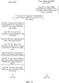
- Step 301 A target uplink controllable gain module obtains a first power Pt of an uplink signal sent by an antenna.
- Step 302 The target uplink controllable gain module sends the first power Pt to a base station.
- the target uplink controllable gain module described in this embodiment may send the first power Pt to the base station according to a communication protocol AISG.
- the target uplink controllable gain module described in this embodiment may send the first power Pt to the base station according to a customized protocol.
- Step 303 The base station obtains a second power Pb of a signal that is output from an output port of the base station.
- Step 304 The base station configures a target attenuation of the base station.
- the target attenuation IL G 0 - (Pb - Pt), where G 0 is an initial gain value of the target uplink controllable gain module.
- Step 305 The base station initiates a PIM suppression function.
- the base station may initiate the PIM suppression function.
- Step 306 The base station determines whether the base station is currently in a downlink no-load state, and if yes, performs step 308, or if no, performs step 307.
- the base station may determine whether the base station is currently in the no-load state, and if yes, performs step 308, or if no, performs step 307.
- Step 307 The base station detects whether a preset time period elapses, and if yes, returns to step 306.
- the base station may preset the preset time period, and a length of the preset time period is not limited in this embodiment.
- the base station may be configured with a timer.
- the base station determines, as a timing start moment by using the timer, a moment when the base station determines that the base station currently is not in the no-load state.
- the base station determines whether a difference between a current moment and the timing start moment is equal to the preset time period, and if yes, it indicates that the base station detects that the preset time period elapses.
- the base station may return to step 306.
- the base station described in this embodiment may count a target quantity of times of continuously performing step 307. If the base station detects that the target quantity of times is greater than a target threshold prestored by the base station, the base station may generate alert information used to prompt a user.
- the alert information is used to inform the user that the base station has been in the no-load state for a long time, and the user may determine, based on the alert information, that the base station cannot perform the PIM suppression function described in this embodiment.
- a value of the target threshold is not limited in this embodiment.
- Step 308 The base station obtains a first received total wideband power RTWP of an uplink of the base station.
- the base station when the base station determines whether the base station is currently in the downlink no-load state, the base station may obtain the first received total wideband power RTWP of the uplink of the base station.
- the received total wideband power detection unit 210 of the base station described in this embodiment may be configured to obtain the first RTWP.
- Step 309 The base station loads target load onto a downlink of the base station.
- the target load is not specifically limited in this embodiment, provided that the target load is less than or equal to a preset threshold.
- the preset threshold is 100% is used for description in this embodiment.
- the base station loads 100% load onto the downlink of the base station.
- Step 310 The base station obtains a second RTWP of the uplink of the base station.
- the base station may obtain the second RTWP of the uplink of the base station.
- Step 311 If the base station detects that an RTWP degrades, the base station generates first instruction information.
- the base station determines that the current RTWP degrades, and the base station may generate the first instruction information.
- the first instruction information in this embodiment is used to instruct the target uplink controllable gain module to increase the initial gain value G 0 by step measured in target preset amounts.
- Step 312 The base station sends the first instruction information to the target uplink controllable gain module.
- Step 313 The target uplink controllable gain module increases, according to the first instruction information, an initial gain value G 0 by step measured in target preset amounts.
- Step 314 The base station controls a gain of an uplink receive channel of the base station to attenuate by step measured in the target preset amounts, to keep a gain of the base station constant.
- the target uplink controllable gain module increases, by step, the initial gain value G 0 stored in the target uplink controllable gain module.
- the base station attenuates the gain of uplink receive channel of the base station by step measured in the target preset amounts.
- the target uplink controllable gain module increases the initial gain value G 0 by step and the base station attenuates the gain of the uplink receive channel of the base station by step are optional examples and impose no limitation, provided that a gain by which the initial gain value G 0 is increased by the target uplink controllable gain module is equal to an attenuation by which the gain of the uplink receive channel of the base station is attenuated. In other words, a gain change of the target uplink controllable gain module is equal to a gain change of the base station.
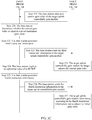
- Step 315 The base station determines whether an absolute value of a difference between the first RTWP and the second RTWP is less than or equal to a preset value, and if yes, performs step 316.
- step 315 in a process of performing step 313 and step 315 to adjust the gain, the base station determines whether the absolute value of the difference between the first RTWP and the second RTWP is less than or equal to the preset value. It can be learned that in this embodiment, step 315 is performed in the process of performing step 313 and step 314.
- a specific value of the preset value is not limited in this embodiment.
- that the preset value is 0 is used as an example in this embodiment.
- the base station determines whether the first RTWP is equal to the second RTWP.
- the target uplink controllable gain module may continuously adjust the initial gain value G 0 , and the base station may also continuously adjust the gain of the uplink receive channel of the base station until the absolute value of the difference between the first RTWP and the second RTWP is less than or equal to the preset value.
- Step 316 The base station generates second instruction information.
- the base station when the base station determines that the absolute value of the difference between the first RTWP and the second RTWP is less than or equal to the preset value, the base station may generate the second instruction information.
- the second instruction information is used to instruct the target uplink controllable gain module no longer to adjust a gain value.
- the target uplink controllable gain module increases the initial gain value G 0 by step measured in the target preset amounts, until the base station performs step 315 to determine that the absolute value of the difference between the first RTWP and the second RTWP is less than or equal to the preset value. Then, the base station instructs, by using the second instruction information, the target uplink controllable gain module no longer to adjust the gain value.
- the gain value in this step is a gain value that is obtained by adjusting the initial gain value G 0 by step by the target uplink controllable gain module.
- Step 317 The base station sends the second instruction information to the target uplink controllable gain module.
- Step 318 The target uplink controllable gain module no longer adjusts a gain value.
- step 319 may be further performed in the method described in this embodiment.
- Step 319 The base station obtains a current gain value G T of the target uplink controllable gain module.
- the base station may obtain the current gain value G T .
- Step 320 The base station determines whether the current gain value G T is equal to a preset maximum gain value, and if no, continues to perform step 313, or if yes, performs step 321.
- the target uplink controllable gain module may continue to increase the initial gain value G 0 by step measured in the target preset amounts.
- the base station continues to perform step 321.
- Step 321 The base station generates third instruction information.
- the third instruction information is used to instruct the target uplink controllable gain module no longer to adjust the current gain value G T .
- Step 322 The base station sends the third instruction information to the target uplink controllable gain module.
- Step 323 The target uplink controllable gain module no longer adjusts the current gain value G T .
- step 319 to step 323 and performing step 315 to step 317 is not limited in this embodiment.
- the base station determines, in a process of performing step 315 to step 317, that the absolute value of the difference between the first RTWP and the second RTWP is less than or equal to the preset value, regardless of whether the current gain value G T is equal to the preset maximum gain value in a process of performing step 319 to step 323, the base station performs step 317 to instruct the target uplink controllable gain module no longer to adjust the gain value.
- the base station determines, in a process of performing step 315 to step 317, that the absolute value of the difference between the first RTWP and the second RTWP is greater than the preset value, if the current gain value G T is equal to the preset maximum gain value in a process of performing step 319 to step 323, the base station performs step 322 to instruct the target uplink controllable gain module no longer to adjust the current gain value G T .
- the base station continues to perform step 315 to step 317 and step 319 to step 323.
- Step 324 The base station displays an optimized value of an RTWP.
- the base station when determining that the current gain value G T is equal to the preset maximum gain value, the base station may perform step 324.
- the optimized value of the RTWP in this embodiment is the difference between the first RTWP and the second RTWP.
- step 325 described in this embodiment may be performed.
- Step 325 The base station generates fourth instruction information.
- the base station when the base station determines that the first RTWP is equal to the second RTWP, the base station generates the fourth instruction information.
- the fourth instruction information is used to instruct the target uplink controllable gain module not to adjust the initial gain value G 0 .
- Step 326 The base station sends the fourth instruction information to the target uplink controllable gain module.
- Step 327 The target uplink controllable gain module determines, according to the fourth instruction information, not to adjust the initial gain value G 0 .
- the base station in a process of adjusting a gain of the target uplink controllable gain module, can maintain the target attenuation constant, reduce a PIM requirement of the passive intermodulation suppression system, and improve sensitivity of uplink reception of the base station.
- a plurality of signals at a same frequency band or different frequency bands can share a feeder, and a remote radio unit RRU does not need to be mounted on a tower. It can be learned that according to the method described in this embodiment, no high costs of tower reinforcement or feeder addition are caused.
- the method described in this embodiment can be applicable to frequency bands of various signals, to avoid a case in which a frequency band auctioned by an operator is unusable on some tower stations.
- the base station 201 the antenna 202, the target uplink controllable gain module 203, the first jumper 204, the second jumper 205, the feeder 206, and the third jumper 207, also refer to the embodiment shown in FIG. 2 .
- two target uplink controllable gain modules 203 are disposed between the base station 201 and the antenna 202.
- a specific quantity of target uplink controllable gain modules 203 is not further described in this embodiment.
- different target uplink controllable gain modules 203 may perform gain control on signals at a same frequency or different frequencies. Details are not described in this embodiment.
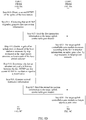
- the passive intermodulation suppression system described in this embodiment can implement the passive intermodulation suppression method shown in FIG. 3A to FIG. 3C .
- FIG. 3A to FIG. 3C Details are not described in this embodiment again.
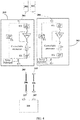
- the target uplink controllable gain module 203 includes an output transmit band-pass filter 501, a receive prefilter 502, a receive postfilter 503, a power detection module 504, a controllable attenuator 505, a low noise amplifier 506, a base-station-side port 507, and an antenna-side port 508.
- the antenna-side port 508 is connected to a first end of the output transmit band-pass filter 501, and a second end of the output transmit band-pass filter 501 is connected to the base-station-side port 507.
- the antenna-side port 508 is further connected to a first end of the receive prefilter 502.
- a second end of the receive prefilter 502 is connected to an input end of the low noise amplifier 506 by using a first RF switch 509.
- An output end of the low noise amplifier 506 is connected to a first end of the controllable attenuator 505 by using a second RF switch 510.
- a second end of the controllable attenuator 505 is connected to a first end of the receive postfilter 503.
- a second end of the receive postfilter 503 is connected to the base-station-side port 507.
- the receive prefilter 502 is configured to separate an uplink signal coupled from an antenna
- the low noise amplifier 506 is configured to amplify the uplink signal
- the controllable attenuator 505 is configured to control a gain of an amplified uplink signal
- the receive postfilter 503 is configured to filter an uplink signal obtained through gain control
- the receive postfilter 503 is configured to combine a downlink signal and an uplink signal at the base-station-side port 507
- the power detection module 504 is configured to detect a downlink power.
- An uplink signal RX coupled from a port of the antenna 202 goes through the receive prefilter 502 of the target uplink controllable gain module 203, and then is amplified by the low noise amplifier 506.
- the controllable attenuator 505 performs gain control on an amplified uplink signal, and then the receive postfilter 503 filters an uplink signal obtained through the gain control.
- a combined signal enters the base station port by using the second jumper 205 and the feeder 206.
- a transmit signal of the base station is output through the base station port, goes through the power detection module 504 and the output transmit band-pass filter 501 of the target uplink controllable gain module 203, goes along the first jumper 204, and is radiated to the air through the antenna port.
- the target uplink controllable gain module 203 described in this embodiment may be integrated into a tower-mounted amplifier TMA, a combiner, a splitter, or the antenna.
- a specific manner of disposing the target uplink controllable gain module 203 is not limited in this embodiment, provided that the target uplink controllable gain module 203 described in this embodiment can perform the passive intermodulation suppression method shown in FIG. 3A to FIG. 3C .
- the passive intermodulation suppression system described in this embodiment may be applied to a multi-frequency system.
- the passive intermodulation suppression system described in this embodiment can eliminate PIM generated by signals at various frequency bands, without mounting a remote radio unit RRU on a tower and/or adding a feeder.
- the passive intermodulation suppression system includes the base station 701, the antenna 702, a target uplink controllable gain module 703, a first jumper 704, a second jumper 705, a feeder 706, and a third jumper 707.
- the passive intermodulation suppression system described in this embodiment further includes a passive intermodulation suppression control module 708, and the passive intermodulation suppression control module 708 is connected and disposed between the base station 701 and the target uplink controllable gain module 703.
- the passive intermodulation suppression control module 708 described in this embodiment can perform a passive intermodulation suppression method.
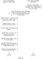
- the following describes, with reference to FIG. 8A to FIG. 8C , a specific process of performing the passive intermodulation suppression method by the passive intermodulation suppression control module 708.
- Step 801 A target uplink controllable gain module obtains a first power Pt of an uplink signal sent by an antenna.
- step 301 shown in FIG. 3A For details about a specific process of performing step 801 described in this embodiment, refer to step 301 shown in FIG. 3A . Details are not described again.
- Step 802 The target uplink controllable gain module sends the first power Pt to a passive intermodulation suppression control module.
- Step 803 The passive intermodulation suppression control module obtains a second power Pb of a signal that is output from an output port of a base station.
- Step 804 The passive intermodulation suppression control module configures a target attenuation of the base station.
- Step 805 The passive intermodulation suppression control module initiates a PIM suppression function.
- Step 806 The passive intermodulation suppression control module determines whether the base station is currently in a downlink no-load state, and if yes, performs step 808, or if no, performs step 807.
- Step 807 The passive intermodulation suppression control module detects whether a preset time period elapses, and if yes, returns to step 806.
- Step 808 The passive intermodulation suppression control module obtains a first received total wideband power RTWP of an uplink of the base station.
- Step 809 The passive intermodulation suppression control module loads target load onto a downlink of the base station.
- Step 810 The passive intermodulation suppression control module obtains a second RTWP of the uplink of the base station.
- Step 811 If the passive intermodulation suppression control module detects that an RTWP degrades, the passive intermodulation suppression control module generates first instruction information.
- Step 812 The passive intermodulation suppression control module sends the first instruction information to the target uplink controllable gain module.
- Step 813 The target uplink controllable gain module increases, according to the first instruction information, an initial gain value G 0 by step measured in target preset amounts.
- Step 814 The passive intermodulation suppression control module controls a gain of an uplink receive channel of the base station to attenuate by step measured in the target preset amounts, to keep a gain of the base station constant.
- Step 815 The passive intermodulation suppression control module determines whether an absolute value of a difference between the first RTWP and the second RTWP is less than or equal to a preset value, and if yes, performs step 816.
- Step 816 The passive intermodulation suppression control module generates second instruction information.
- Step 817 The passive intermodulation suppression control module sends the second instruction information to the target uplink controllable gain module.
- Step 818 The target uplink controllable gain module no longer adjusts a gain value.
- Step 819 The passive intermodulation suppression control module obtains a current gain value G T of the target uplink controllable gain module.
- Step 820 The passive intermodulation suppression control module determines whether the current gain value G T is equal to a preset maximum gain value, and if no, continues to perform step 813, or if yes, performs step 821.
- Step 821 The passive intermodulation suppression control module generates third instruction information.
- Step 822 The passive intermodulation suppression control module sends the third instruction information to the target uplink controllable gain module.
- Step 823 The target uplink controllable gain module no longer adjusts the current gain value G T .
- Step 824 The passive intermodulation suppression control module displays an optimized value of an RTWP.
- Step 825 The passive intermodulation suppression control module generates fourth instruction information.
- Step 826 The passive intermodulation suppression control module sends the fourth instruction information to the target uplink controllable gain module.
- Step 827 The target uplink controllable gain module determines, according to the fourth instruction information, not to adjust the initial gain value G 0 .
- step 801 to step 827 described in this embodiment refer to the passive intermodulation suppression method that is performed by the base station and that is shown in FIG. 3A to FIG. 3C .
- FIG. 3A to FIG. 3C For a specific process of the passive intermodulation suppression method performed by the passive intermodulation suppression control module in this embodiment, refer to FIG. 3A to FIG. 3C . Details are not described again.
- the passive intermodulation suppression control module in a process of adjusting a gain of the target uplink controllable gain module, can maintain the target attenuation constant, reduce a PIM requirement of the passive intermodulation suppression system, and improve sensitivity of uplink reception of the base station.
- a plurality of signals at a same frequency band or different frequency bands can share a feeder, and a remote radio unit RRU does not need to be mounted on a tower. It can be learned that according to the method described in this embodiment, no high costs of tower reinforcement or feeder addition are caused.
- the method described in this embodiment can be applicable to frequency bands of various signals, to avoid a case in which a frequency band auctioned by an operator is unusable on some tower stations.
Landscapes
- Engineering & Computer Science (AREA)
- Computer Networks & Wireless Communication (AREA)
- Signal Processing (AREA)
- Mobile Radio Communication Systems (AREA)
- Quality & Reliability (AREA)
- Physics & Mathematics (AREA)
- Electromagnetism (AREA)
- Transceivers (AREA)
- Noise Elimination (AREA)
Applications Claiming Priority (2)
| Application Number | Priority Date | Filing Date | Title |
|---|---|---|---|
| CN201611247608.XA CN106849970B (zh) | 2016-12-29 | 2016-12-29 | 一种无源互调抑制方法以及无源互调抑制系统 |
| PCT/CN2017/118533 WO2018121507A1 (zh) | 2016-12-29 | 2017-12-26 | 一种无源互调抑制方法以及无源互调抑制系统 |
Publications (3)
| Publication Number | Publication Date |
|---|---|
| EP3553954A1 true EP3553954A1 (de) | 2019-10-16 |
| EP3553954A4 EP3553954A4 (de) | 2020-01-15 |
| EP3553954B1 EP3553954B1 (de) | 2022-02-23 |
Family
ID=59112780
Family Applications (1)
| Application Number | Title | Priority Date | Filing Date |
|---|---|---|---|
| EP17887194.3A Active EP3553954B1 (de) | 2016-12-29 | 2017-12-26 | Verfahren zur passiven intermodulationsunterdrückung und system zur passiven intermodulationsunterdrückung |
Country Status (5)
| Country | Link |
|---|---|
| US (1) | US10574280B2 (de) |
| EP (1) | EP3553954B1 (de) |
| JP (1) | JP6794554B2 (de) |
| CN (1) | CN106849970B (de) |
| WO (1) | WO2018121507A1 (de) |
Families Citing this family (9)
| Publication number | Priority date | Publication date | Assignee | Title |
|---|---|---|---|---|
| CN106849970B (zh) | 2016-12-29 | 2019-10-18 | 上海华为技术有限公司 | 一种无源互调抑制方法以及无源互调抑制系统 |
| WO2019080124A1 (zh) * | 2017-10-27 | 2019-05-02 | 华为技术有限公司 | 多通道无源互调数字抵消电路 |
| CN109495127B (zh) * | 2018-09-27 | 2021-09-03 | 香港梵行科技有限公司 | 自适应抵消无源互调信号的装置、方法及应用设备 |
| CN109495124B (zh) * | 2018-09-27 | 2021-09-03 | 香港梵行科技有限公司 | 一种自适应抵消无源互调信号的方法、装置及应用设备 |
| CN109995394B (zh) * | 2018-09-29 | 2022-02-11 | 香港梵行科技有限公司 | 一种自适应抵消无源互调信号的装置及其方法 |
| CN112701496B (zh) * | 2019-10-22 | 2024-07-26 | 普罗斯技术(澳大利亚)有限公司 | 一种基站天线 |
| CN114257335B (zh) * | 2020-09-25 | 2025-04-08 | 中兴通讯股份有限公司 | 数据处理方法、装置和系统、电子设备、介质 |
| CN116015370B (zh) * | 2022-12-15 | 2026-04-10 | 维沃移动通信有限公司 | 天线控制电路及其控制方法以及电子设备 |
| CN116704848B (zh) * | 2023-08-04 | 2023-10-03 | 南京航天工业科技有限公司 | 一种收发同时的无人机机载目标模拟方法、装置及系统 |
Family Cites Families (28)
| Publication number | Priority date | Publication date | Assignee | Title |
|---|---|---|---|---|
| US5722063A (en) * | 1994-12-16 | 1998-02-24 | Qualcomm Incorporated | Method and apparatus for increasing receiver immunity to interference |
| CA2175860C (en) * | 1995-06-02 | 2001-03-27 | Randall Wayne Rich | Apparatus and method for optimizing the quality of a received signal in a radio receiver |
| US5697081A (en) * | 1995-09-12 | 1997-12-09 | Oki Telecom, Inc. | Intermodulation distortion reduction circuit utilizing variable attenuation |
| US5926747A (en) * | 1996-09-05 | 1999-07-20 | Airnet Communications Corp. | Method and apparatus for dynamically optimizing the forward-link transmit power of a broadband multi-carrier radio signal |
| JP2993558B2 (ja) * | 1996-10-23 | 1999-12-20 | 日本電気株式会社 | 受信機 |
| US6236863B1 (en) * | 1997-03-31 | 2001-05-22 | Oki Telecom, Inc. | Comprehensive transmitter power control system for radio telephones |
| US6230031B1 (en) * | 1997-03-31 | 2001-05-08 | Oki Telecom, Inc. | Power amplifying circuitry for wireless radio transceivers |
| JP2000068870A (ja) * | 1998-08-20 | 2000-03-03 | Matsushita Electric Ind Co Ltd | インターモジュレーションを防止する受信装置及び受信方法 |
| CN1131650C (zh) * | 1998-09-07 | 2003-12-17 | Lg情报通信株式会社 | 无线通信系统基站发射机的增频变频器及其输出控制方法 |
| JP3564437B2 (ja) * | 2001-07-25 | 2004-09-08 | 埼玉日本電気株式会社 | 無線基地局システムの受信部監視システム及び監視方法 |
| US6892080B2 (en) * | 2001-11-27 | 2005-05-10 | Arrista Technologies, Inc. | Booster amplifier for cellular telephone cradles |
| US7127211B2 (en) * | 2002-02-21 | 2006-10-24 | Telefonaktiebolaget Lm Ericsson (Publ) | Method and apparatus for reduced intermodulation distortion in a radio transceiver |
| US7197289B2 (en) * | 2003-03-06 | 2007-03-27 | Interdigital Technology Corporation | Automatic gain control for a wireless transmit/receive unit in a time slotted data transmissions |
| JP2009027329A (ja) * | 2007-07-18 | 2009-02-05 | Niigata Seimitsu Kk | 自動利得制御回路 |
| CN101141714A (zh) * | 2007-09-26 | 2008-03-12 | 华为技术有限公司 | 一种基站兼容高增益塔顶放大器的方法和装置 |
| US8705595B2 (en) * | 2011-05-06 | 2014-04-22 | Telefonaktiebolaget L M Ericsson (Publ) | Digital output power measurement in radio communication systems |
| US8624657B2 (en) * | 2011-07-28 | 2014-01-07 | Mediatek Singapore Pte. Ltd. | Squaring circuit, integrated circuit, wireless communication unit and method therefor |
| CN103368588A (zh) * | 2012-03-28 | 2013-10-23 | 中兴通讯股份有限公司 | 一种处理基站上行外部干扰的方法、装置及系统 |
| CN103517299B (zh) * | 2012-06-18 | 2018-11-20 | 罗森伯格(上海)通信技术有限公司 | 一种基站互调信号检测方法及系统 |
| WO2014085345A1 (en) * | 2012-11-30 | 2014-06-05 | P-Wave Holdings, Llc | Built-in passive intermodulation detector for base station equipment |
| WO2015171031A1 (en) * | 2014-05-09 | 2015-11-12 | Telefonaktiebolaget L M Ericsson (Publ) | Method and node for controlling an uplink noise figure and gain |
| CN103986482B (zh) * | 2014-05-27 | 2016-02-03 | 北京理工大学 | 一种基于自适应滤波的无源互调干扰抑制方法 |
| BR112016028004A8 (pt) * | 2014-07-10 | 2017-08-22 | Ericsson Telefon Ab L M | método para cancelar interferência de intermodulação, receptor, transceptor, nó de comunicação sem fio, e, meio de armazenamento legível por computador |
| CN104486282B (zh) * | 2014-12-15 | 2018-02-13 | 成都康特数字广播电视设备有限公司 | 射频多载波互调抑制装置 |
| KR20160112131A (ko) * | 2015-03-18 | 2016-09-28 | (주)에이더블유에스아이 | 이동통신 멀티 밴드 pimd 억제 장치 및 방법 |
| CN104967494B (zh) * | 2015-04-30 | 2018-05-11 | 华为技术有限公司 | 一种测试方法、设备和系统 |
| CN104993880B (zh) * | 2015-05-27 | 2018-06-19 | 武汉虹信通信技术有限责任公司 | 基于能量和相位的基站天线互调参数化分析方法 |
| CN106849970B (zh) * | 2016-12-29 | 2019-10-18 | 上海华为技术有限公司 | 一种无源互调抑制方法以及无源互调抑制系统 |
-
2016
- 2016-12-29 CN CN201611247608.XA patent/CN106849970B/zh active Active
-
2017
- 2017-12-26 JP JP2019535907A patent/JP6794554B2/ja active Active
- 2017-12-26 EP EP17887194.3A patent/EP3553954B1/de active Active
- 2017-12-26 WO PCT/CN2017/118533 patent/WO2018121507A1/zh not_active Ceased
-
2019
- 2019-06-27 US US16/454,225 patent/US10574280B2/en active Active
Also Published As
| Publication number | Publication date |
|---|---|
| CN106849970A (zh) | 2017-06-13 |
| CN106849970B (zh) | 2019-10-18 |
| US20190319656A1 (en) | 2019-10-17 |
| US10574280B2 (en) | 2020-02-25 |
| WO2018121507A1 (zh) | 2018-07-05 |
| EP3553954A4 (de) | 2020-01-15 |
| JP2020503789A (ja) | 2020-01-30 |
| EP3553954B1 (de) | 2022-02-23 |
| JP6794554B2 (ja) | 2020-12-02 |
Similar Documents
| Publication | Publication Date | Title |
|---|---|---|
| US10574280B2 (en) | Passive intermodulation suppression method and passive intermodulation suppression system | |
| US10148341B2 (en) | Independent band detection for network protection | |
| CN102711151B (zh) | 智能数字无线直放站的控制方法及智能数字无线直放站 | |
| US9059794B2 (en) | Method of generating interference signals and device to carry out such a method | |
| US10873387B2 (en) | Signal booster with spectrally adjacent bands | |
| WO2008147506A1 (en) | On frequency repeater with agc stability determination | |
| US10659142B1 (en) | Independent band detection for network protection | |
| WO2015069774A1 (en) | Multimode wireless systems and methods | |
| CN110622440A (zh) | 具有自动增益控制的信号增强器系统 | |
| CN102833884A (zh) | 双模移动通信终端 | |
| JPH07336294A (ja) | セルラ無線基地局装置 | |
| CN110352570A (zh) | 具有频谱相邻频带的信号增强器 | |
| CN107623544B (zh) | 一种智能直放站及基于智能直放站的通信方法 | |
| TWI575970B (zh) | 提高在擁擠環境之內部量測機率的系統及方法 | |
| US20190090209A1 (en) | Oscillation mitigation using successive approximation in a signal booster | |
| EP3474455B1 (de) | Kommunikationsvorrichtung | |
| CN107835045A (zh) | 一种移动终端的对讲信号处理方法、电路及移动终端 | |
| KR101852997B1 (ko) | 간섭 제거 중계 장치 | |
| EP3499745B1 (de) | An einem turm montierter verstärker | |
| CN110366829A (zh) | 具有频谱相邻频带的信号增强器 | |
| EP3577797B1 (de) | Reduzierung der schwingung in einem signalverstärker | |
| WO2010056222A1 (en) | A wireless repeater with a locate mode | |
| KR101288607B1 (ko) | 이동형 중계장치 | |
| KR100299092B1 (ko) | 기지국의 고주파 처리장치 | |
| EP3577794A1 (de) | Bandspezifische detektion in einem signalverstärker |
Legal Events
| Date | Code | Title | Description |
|---|---|---|---|
| STAA | Information on the status of an ep patent application or granted ep patent |
Free format text: STATUS: THE INTERNATIONAL PUBLICATION HAS BEEN MADE |
|
| PUAI | Public reference made under article 153(3) epc to a published international application that has entered the european phase |
Free format text: ORIGINAL CODE: 0009012 |
|
| STAA | Information on the status of an ep patent application or granted ep patent |
Free format text: STATUS: REQUEST FOR EXAMINATION WAS MADE |
|
| 17P | Request for examination filed |
Effective date: 20190709 |
|
| AK | Designated contracting states |
Kind code of ref document: A1 Designated state(s): AL AT BE BG CH CY CZ DE DK EE ES FI FR GB GR HR HU IE IS IT LI LT LU LV MC MK MT NL NO PL PT RO RS SE SI SK SM TR |
|
| AX | Request for extension of the european patent |
Extension state: BA ME |
|
| A4 | Supplementary search report drawn up and despatched |
Effective date: 20191218 |
|
| RIC1 | Information provided on ipc code assigned before grant |
Ipc: H04B 1/10 20060101AFI20191212BHEP Ipc: H04B 1/12 20060101ALI20191212BHEP |
|
| DAV | Request for validation of the european patent (deleted) | ||
| DAX | Request for extension of the european patent (deleted) | ||
| GRAP | Despatch of communication of intention to grant a patent |
Free format text: ORIGINAL CODE: EPIDOSNIGR1 |
|
| STAA | Information on the status of an ep patent application or granted ep patent |
Free format text: STATUS: GRANT OF PATENT IS INTENDED |
|
| GRAJ | Information related to disapproval of communication of intention to grant by the applicant or resumption of examination proceedings by the epo deleted |
Free format text: ORIGINAL CODE: EPIDOSDIGR1 |
|
| GRAP | Despatch of communication of intention to grant a patent |
Free format text: ORIGINAL CODE: EPIDOSNIGR1 |
|
| INTG | Intention to grant announced |
Effective date: 20211011 |
|
| INTG | Intention to grant announced |
Effective date: 20211027 |
|
| GRAS | Grant fee paid |
Free format text: ORIGINAL CODE: EPIDOSNIGR3 |
|
| GRAA | (expected) grant |
Free format text: ORIGINAL CODE: 0009210 |
|
| STAA | Information on the status of an ep patent application or granted ep patent |
Free format text: STATUS: THE PATENT HAS BEEN GRANTED |
|
| AK | Designated contracting states |
Kind code of ref document: B1 Designated state(s): AL AT BE BG CH CY CZ DE DK EE ES FI FR GB GR HR HU IE IS IT LI LT LU LV MC MK MT NL NO PL PT RO RS SE SI SK SM TR |
|
| REG | Reference to a national code |
Ref country code: GB Ref legal event code: FG4D |
|
| REG | Reference to a national code |
Ref country code: CH Ref legal event code: EP |
|
| REG | Reference to a national code |
Ref country code: AT Ref legal event code: REF Ref document number: 1471248 Country of ref document: AT Kind code of ref document: T Effective date: 20220315 |
|
| REG | Reference to a national code |
Ref country code: IE Ref legal event code: FG4D |
|
| REG | Reference to a national code |
Ref country code: DE Ref legal event code: R096 Ref document number: 602017053874 Country of ref document: DE |
|
| REG | Reference to a national code |
Ref country code: LT Ref legal event code: MG9D |
|
| REG | Reference to a national code |
Ref country code: NL Ref legal event code: MP Effective date: 20220223 |
|
| REG | Reference to a national code |
Ref country code: AT Ref legal event code: MK05 Ref document number: 1471248 Country of ref document: AT Kind code of ref document: T Effective date: 20220223 |
|
| PG25 | Lapsed in a contracting state [announced via postgrant information from national office to epo] |
Ref country code: SE Free format text: LAPSE BECAUSE OF FAILURE TO SUBMIT A TRANSLATION OF THE DESCRIPTION OR TO PAY THE FEE WITHIN THE PRESCRIBED TIME-LIMIT Effective date: 20220223 Ref country code: RS Free format text: LAPSE BECAUSE OF FAILURE TO SUBMIT A TRANSLATION OF THE DESCRIPTION OR TO PAY THE FEE WITHIN THE PRESCRIBED TIME-LIMIT Effective date: 20220223 Ref country code: PT Free format text: LAPSE BECAUSE OF FAILURE TO SUBMIT A TRANSLATION OF THE DESCRIPTION OR TO PAY THE FEE WITHIN THE PRESCRIBED TIME-LIMIT Effective date: 20220623 Ref country code: NO Free format text: LAPSE BECAUSE OF FAILURE TO SUBMIT A TRANSLATION OF THE DESCRIPTION OR TO PAY THE FEE WITHIN THE PRESCRIBED TIME-LIMIT Effective date: 20220523 Ref country code: NL Free format text: LAPSE BECAUSE OF FAILURE TO SUBMIT A TRANSLATION OF THE DESCRIPTION OR TO PAY THE FEE WITHIN THE PRESCRIBED TIME-LIMIT Effective date: 20220223 Ref country code: LT Free format text: LAPSE BECAUSE OF FAILURE TO SUBMIT A TRANSLATION OF THE DESCRIPTION OR TO PAY THE FEE WITHIN THE PRESCRIBED TIME-LIMIT Effective date: 20220223 Ref country code: HR Free format text: LAPSE BECAUSE OF FAILURE TO SUBMIT A TRANSLATION OF THE DESCRIPTION OR TO PAY THE FEE WITHIN THE PRESCRIBED TIME-LIMIT Effective date: 20220223 Ref country code: ES Free format text: LAPSE BECAUSE OF FAILURE TO SUBMIT A TRANSLATION OF THE DESCRIPTION OR TO PAY THE FEE WITHIN THE PRESCRIBED TIME-LIMIT Effective date: 20220223 Ref country code: BG Free format text: LAPSE BECAUSE OF FAILURE TO SUBMIT A TRANSLATION OF THE DESCRIPTION OR TO PAY THE FEE WITHIN THE PRESCRIBED TIME-LIMIT Effective date: 20220523 |
|
| PG25 | Lapsed in a contracting state [announced via postgrant information from national office to epo] |
Ref country code: PL Free format text: LAPSE BECAUSE OF FAILURE TO SUBMIT A TRANSLATION OF THE DESCRIPTION OR TO PAY THE FEE WITHIN THE PRESCRIBED TIME-LIMIT Effective date: 20220223 Ref country code: LV Free format text: LAPSE BECAUSE OF FAILURE TO SUBMIT A TRANSLATION OF THE DESCRIPTION OR TO PAY THE FEE WITHIN THE PRESCRIBED TIME-LIMIT Effective date: 20220223 Ref country code: GR Free format text: LAPSE BECAUSE OF FAILURE TO SUBMIT A TRANSLATION OF THE DESCRIPTION OR TO PAY THE FEE WITHIN THE PRESCRIBED TIME-LIMIT Effective date: 20220524 Ref country code: FI Free format text: LAPSE BECAUSE OF FAILURE TO SUBMIT A TRANSLATION OF THE DESCRIPTION OR TO PAY THE FEE WITHIN THE PRESCRIBED TIME-LIMIT Effective date: 20220223 Ref country code: AT Free format text: LAPSE BECAUSE OF FAILURE TO SUBMIT A TRANSLATION OF THE DESCRIPTION OR TO PAY THE FEE WITHIN THE PRESCRIBED TIME-LIMIT Effective date: 20220223 |
|
| PG25 | Lapsed in a contracting state [announced via postgrant information from national office to epo] |
Ref country code: IS Free format text: LAPSE BECAUSE OF FAILURE TO SUBMIT A TRANSLATION OF THE DESCRIPTION OR TO PAY THE FEE WITHIN THE PRESCRIBED TIME-LIMIT Effective date: 20220623 |
|
| PG25 | Lapsed in a contracting state [announced via postgrant information from national office to epo] |
Ref country code: SM Free format text: LAPSE BECAUSE OF FAILURE TO SUBMIT A TRANSLATION OF THE DESCRIPTION OR TO PAY THE FEE WITHIN THE PRESCRIBED TIME-LIMIT Effective date: 20220223 Ref country code: SK Free format text: LAPSE BECAUSE OF FAILURE TO SUBMIT A TRANSLATION OF THE DESCRIPTION OR TO PAY THE FEE WITHIN THE PRESCRIBED TIME-LIMIT Effective date: 20220223 Ref country code: RO Free format text: LAPSE BECAUSE OF FAILURE TO SUBMIT A TRANSLATION OF THE DESCRIPTION OR TO PAY THE FEE WITHIN THE PRESCRIBED TIME-LIMIT Effective date: 20220223 Ref country code: EE Free format text: LAPSE BECAUSE OF FAILURE TO SUBMIT A TRANSLATION OF THE DESCRIPTION OR TO PAY THE FEE WITHIN THE PRESCRIBED TIME-LIMIT Effective date: 20220223 Ref country code: DK Free format text: LAPSE BECAUSE OF FAILURE TO SUBMIT A TRANSLATION OF THE DESCRIPTION OR TO PAY THE FEE WITHIN THE PRESCRIBED TIME-LIMIT Effective date: 20220223 Ref country code: CZ Free format text: LAPSE BECAUSE OF FAILURE TO SUBMIT A TRANSLATION OF THE DESCRIPTION OR TO PAY THE FEE WITHIN THE PRESCRIBED TIME-LIMIT Effective date: 20220223 |
|
| REG | Reference to a national code |
Ref country code: DE Ref legal event code: R097 Ref document number: 602017053874 Country of ref document: DE |
|
| PG25 | Lapsed in a contracting state [announced via postgrant information from national office to epo] |
Ref country code: AL Free format text: LAPSE BECAUSE OF FAILURE TO SUBMIT A TRANSLATION OF THE DESCRIPTION OR TO PAY THE FEE WITHIN THE PRESCRIBED TIME-LIMIT Effective date: 20220223 |
|
| PLBE | No opposition filed within time limit |
Free format text: ORIGINAL CODE: 0009261 |
|
| STAA | Information on the status of an ep patent application or granted ep patent |
Free format text: STATUS: NO OPPOSITION FILED WITHIN TIME LIMIT |
|
| 26N | No opposition filed |
Effective date: 20221124 |
|
| PG25 | Lapsed in a contracting state [announced via postgrant information from national office to epo] |
Ref country code: SI Free format text: LAPSE BECAUSE OF FAILURE TO SUBMIT A TRANSLATION OF THE DESCRIPTION OR TO PAY THE FEE WITHIN THE PRESCRIBED TIME-LIMIT Effective date: 20220223 |
|
| PG25 | Lapsed in a contracting state [announced via postgrant information from national office to epo] |
Ref country code: IT Free format text: LAPSE BECAUSE OF FAILURE TO SUBMIT A TRANSLATION OF THE DESCRIPTION OR TO PAY THE FEE WITHIN THE PRESCRIBED TIME-LIMIT Effective date: 20220223 |
|
| REG | Reference to a national code |
Ref country code: CH Ref legal event code: PL |
|
| GBPC | Gb: european patent ceased through non-payment of renewal fee |
Effective date: 20221226 |
|
| REG | Reference to a national code |
Ref country code: BE Ref legal event code: MM Effective date: 20221231 |
|
| PG25 | Lapsed in a contracting state [announced via postgrant information from national office to epo] |
Ref country code: LU Free format text: LAPSE BECAUSE OF NON-PAYMENT OF DUE FEES Effective date: 20221226 |
|
| PG25 | Lapsed in a contracting state [announced via postgrant information from national office to epo] |
Ref country code: LI Free format text: LAPSE BECAUSE OF NON-PAYMENT OF DUE FEES Effective date: 20221231 Ref country code: IE Free format text: LAPSE BECAUSE OF NON-PAYMENT OF DUE FEES Effective date: 20221226 Ref country code: GB Free format text: LAPSE BECAUSE OF NON-PAYMENT OF DUE FEES Effective date: 20221226 Ref country code: CH Free format text: LAPSE BECAUSE OF NON-PAYMENT OF DUE FEES Effective date: 20221231 |
|
| PG25 | Lapsed in a contracting state [announced via postgrant information from national office to epo] |
Ref country code: FR Free format text: LAPSE BECAUSE OF NON-PAYMENT OF DUE FEES Effective date: 20221231 Ref country code: BE Free format text: LAPSE BECAUSE OF NON-PAYMENT OF DUE FEES Effective date: 20221231 |
|
| PG25 | Lapsed in a contracting state [announced via postgrant information from national office to epo] |
Ref country code: HU Free format text: LAPSE BECAUSE OF FAILURE TO SUBMIT A TRANSLATION OF THE DESCRIPTION OR TO PAY THE FEE WITHIN THE PRESCRIBED TIME-LIMIT; INVALID AB INITIO Effective date: 20171226 |
|
| PG25 | Lapsed in a contracting state [announced via postgrant information from national office to epo] |
Ref country code: CY Free format text: LAPSE BECAUSE OF FAILURE TO SUBMIT A TRANSLATION OF THE DESCRIPTION OR TO PAY THE FEE WITHIN THE PRESCRIBED TIME-LIMIT Effective date: 20220223 |
|
| PG25 | Lapsed in a contracting state [announced via postgrant information from national office to epo] |
Ref country code: MK Free format text: LAPSE BECAUSE OF FAILURE TO SUBMIT A TRANSLATION OF THE DESCRIPTION OR TO PAY THE FEE WITHIN THE PRESCRIBED TIME-LIMIT Effective date: 20220223 |
|
| PG25 | Lapsed in a contracting state [announced via postgrant information from national office to epo] |
Ref country code: MC Free format text: LAPSE BECAUSE OF FAILURE TO SUBMIT A TRANSLATION OF THE DESCRIPTION OR TO PAY THE FEE WITHIN THE PRESCRIBED TIME-LIMIT Effective date: 20220223 |
|
| PG25 | Lapsed in a contracting state [announced via postgrant information from national office to epo] |
Ref country code: MC Free format text: LAPSE BECAUSE OF FAILURE TO SUBMIT A TRANSLATION OF THE DESCRIPTION OR TO PAY THE FEE WITHIN THE PRESCRIBED TIME-LIMIT Effective date: 20220223 |
|
| PG25 | Lapsed in a contracting state [announced via postgrant information from national office to epo] |
Ref country code: MT Free format text: LAPSE BECAUSE OF FAILURE TO SUBMIT A TRANSLATION OF THE DESCRIPTION OR TO PAY THE FEE WITHIN THE PRESCRIBED TIME-LIMIT Effective date: 20220223 |
|
| PG25 | Lapsed in a contracting state [announced via postgrant information from national office to epo] |
Ref country code: TR Free format text: LAPSE BECAUSE OF FAILURE TO SUBMIT A TRANSLATION OF THE DESCRIPTION OR TO PAY THE FEE WITHIN THE PRESCRIBED TIME-LIMIT Effective date: 20220223 |
|
| PGFP | Annual fee paid to national office [announced via postgrant information from national office to epo] |
Ref country code: DE Payment date: 20251104 Year of fee payment: 9 |