EP3553639A1 - Anzeigevorrichtung - Google Patents
Anzeigevorrichtung Download PDFInfo
- Publication number
- EP3553639A1 EP3553639A1 EP19171352.8A EP19171352A EP3553639A1 EP 3553639 A1 EP3553639 A1 EP 3553639A1 EP 19171352 A EP19171352 A EP 19171352A EP 3553639 A1 EP3553639 A1 EP 3553639A1
- Authority
- EP
- European Patent Office
- Prior art keywords
- display
- information
- touch
- displacement
- unit
- Prior art date
- Legal status (The legal status is an assumption and is not a legal conclusion. Google has not performed a legal analysis and makes no representation as to the accuracy of the status listed.)
- Withdrawn
Links
- 238000006073 displacement reaction Methods 0.000 claims abstract description 254
- 238000000034 method Methods 0.000 claims description 10
- 230000005540 biological transmission Effects 0.000 abstract description 26
- 238000004891 communication Methods 0.000 description 76
- 238000006243 chemical reaction Methods 0.000 description 43
- 230000006870 function Effects 0.000 description 30
- 230000005236 sound signal Effects 0.000 description 21
- 238000004364 calculation method Methods 0.000 description 12
- 230000009471 action Effects 0.000 description 8
- 238000010586 diagram Methods 0.000 description 7
- 230000008859 change Effects 0.000 description 6
- 230000001105 regulatory effect Effects 0.000 description 6
- 230000000694 effects Effects 0.000 description 4
- 230000004044 response Effects 0.000 description 4
- 238000005516 engineering process Methods 0.000 description 3
- 239000004973 liquid crystal related substance Substances 0.000 description 3
- 238000013500 data storage Methods 0.000 description 2
- 230000002093 peripheral effect Effects 0.000 description 2
- 238000010079 rubber tapping Methods 0.000 description 2
- 238000013459 approach Methods 0.000 description 1
- 230000006399 behavior Effects 0.000 description 1
- 230000001276 controlling effect Effects 0.000 description 1
- 238000001514 detection method Methods 0.000 description 1
- 239000000446 fuel Substances 0.000 description 1
- 238000005457 optimization Methods 0.000 description 1
- 230000008569 process Effects 0.000 description 1
- 230000008054 signal transmission Effects 0.000 description 1
Images


Classifications
-
- G—PHYSICS
- G06—COMPUTING; CALCULATING OR COUNTING
- G06F—ELECTRIC DIGITAL DATA PROCESSING
- G06F3/00—Input arrangements for transferring data to be processed into a form capable of being handled by the computer; Output arrangements for transferring data from processing unit to output unit, e.g. interface arrangements
- G06F3/01—Input arrangements or combined input and output arrangements for interaction between user and computer
- G06F3/03—Arrangements for converting the position or the displacement of a member into a coded form
- G06F3/041—Digitisers, e.g. for touch screens or touch pads, characterised by the transducing means
- G06F3/0416—Control or interface arrangements specially adapted for digitisers
-
- B—PERFORMING OPERATIONS; TRANSPORTING
- B60—VEHICLES IN GENERAL
- B60K—ARRANGEMENT OR MOUNTING OF PROPULSION UNITS OR OF TRANSMISSIONS IN VEHICLES; ARRANGEMENT OR MOUNTING OF PLURAL DIVERSE PRIME-MOVERS IN VEHICLES; AUXILIARY DRIVES FOR VEHICLES; INSTRUMENTATION OR DASHBOARDS FOR VEHICLES; ARRANGEMENTS IN CONNECTION WITH COOLING, AIR INTAKE, GAS EXHAUST OR FUEL SUPPLY OF PROPULSION UNITS IN VEHICLES
- B60K35/00—Arrangement of adaptations of instruments
-
- B60K35/10—
-
- B60K35/29—
-
- B60K35/80—
-
- B60K35/85—
-
- G—PHYSICS
- G06—COMPUTING; CALCULATING OR COUNTING
- G06F—ELECTRIC DIGITAL DATA PROCESSING
- G06F3/00—Input arrangements for transferring data to be processed into a form capable of being handled by the computer; Output arrangements for transferring data from processing unit to output unit, e.g. interface arrangements
- G06F3/01—Input arrangements or combined input and output arrangements for interaction between user and computer
- G06F3/03—Arrangements for converting the position or the displacement of a member into a coded form
- G06F3/033—Pointing devices displaced or positioned by the user, e.g. mice, trackballs, pens or joysticks; Accessories therefor
- G06F3/038—Control and interface arrangements therefor, e.g. drivers or device-embedded control circuitry
-
- G—PHYSICS
- G06—COMPUTING; CALCULATING OR COUNTING
- G06F—ELECTRIC DIGITAL DATA PROCESSING
- G06F3/00—Input arrangements for transferring data to be processed into a form capable of being handled by the computer; Output arrangements for transferring data from processing unit to output unit, e.g. interface arrangements
- G06F3/01—Input arrangements or combined input and output arrangements for interaction between user and computer
- G06F3/048—Interaction techniques based on graphical user interfaces [GUI]
- G06F3/0487—Interaction techniques based on graphical user interfaces [GUI] using specific features provided by the input device, e.g. functions controlled by the rotation of a mouse with dual sensing arrangements, or of the nature of the input device, e.g. tap gestures based on pressure sensed by a digitiser
- G06F3/0488—Interaction techniques based on graphical user interfaces [GUI] using specific features provided by the input device, e.g. functions controlled by the rotation of a mouse with dual sensing arrangements, or of the nature of the input device, e.g. tap gestures based on pressure sensed by a digitiser using a touch-screen or digitiser, e.g. input of commands through traced gestures
-
- G—PHYSICS
- G06—COMPUTING; CALCULATING OR COUNTING
- G06F—ELECTRIC DIGITAL DATA PROCESSING
- G06F3/00—Input arrangements for transferring data to be processed into a form capable of being handled by the computer; Output arrangements for transferring data from processing unit to output unit, e.g. interface arrangements
- G06F3/14—Digital output to display device ; Cooperation and interconnection of the display device with other functional units
- G06F3/1415—Digital output to display device ; Cooperation and interconnection of the display device with other functional units with means for detecting differences between the image stored in the host and the images displayed on the displays
-
- G—PHYSICS
- G06—COMPUTING; CALCULATING OR COUNTING
- G06F—ELECTRIC DIGITAL DATA PROCESSING
- G06F3/00—Input arrangements for transferring data to be processed into a form capable of being handled by the computer; Output arrangements for transferring data from processing unit to output unit, e.g. interface arrangements
- G06F3/14—Digital output to display device ; Cooperation and interconnection of the display device with other functional units
- G06F3/1454—Digital output to display device ; Cooperation and interconnection of the display device with other functional units involving copying of the display data of a local workstation or window to a remote workstation or window so that an actual copy of the data is displayed simultaneously on two or more displays, e.g. teledisplay
-
- G—PHYSICS
- G06—COMPUTING; CALCULATING OR COUNTING
- G06T—IMAGE DATA PROCESSING OR GENERATION, IN GENERAL
- G06T1/00—General purpose image data processing
- G06T1/20—Processor architectures; Processor configuration, e.g. pipelining
-
- G—PHYSICS
- G09—EDUCATION; CRYPTOGRAPHY; DISPLAY; ADVERTISING; SEALS
- G09G—ARRANGEMENTS OR CIRCUITS FOR CONTROL OF INDICATING DEVICES USING STATIC MEANS TO PRESENT VARIABLE INFORMATION
- G09G5/00—Control arrangements or circuits for visual indicators common to cathode-ray tube indicators and other visual indicators
- G09G5/12—Synchronisation between the display unit and other units, e.g. other display units, video-disc players
-
- H—ELECTRICITY
- H04—ELECTRIC COMMUNICATION TECHNIQUE
- H04M—TELEPHONIC COMMUNICATION
- H04M1/00—Substation equipment, e.g. for use by subscribers
- H04M1/72—Mobile telephones; Cordless telephones, i.e. devices for establishing wireless links to base stations without route selection
- H04M1/724—User interfaces specially adapted for cordless or mobile telephones
- H04M1/72403—User interfaces specially adapted for cordless or mobile telephones with means for local support of applications that increase the functionality
- H04M1/72409—User interfaces specially adapted for cordless or mobile telephones with means for local support of applications that increase the functionality by interfacing with external accessories
- H04M1/72412—User interfaces specially adapted for cordless or mobile telephones with means for local support of applications that increase the functionality by interfacing with external accessories using two-way short-range wireless interfaces
-
- B60K2360/1438—
-
- B60K2360/1442—
-
- B60K2360/184—
-
- B60K2360/55—
-
- B60K2360/563—
-
- B60K2360/566—
-
- B60K2360/569—
-
- B60K2360/573—
-
- B60K2360/589—
-
- G—PHYSICS
- G06—COMPUTING; CALCULATING OR COUNTING
- G06F—ELECTRIC DIGITAL DATA PROCESSING
- G06F2203/00—Indexing scheme relating to G06F3/00 - G06F3/048
- G06F2203/038—Indexing scheme relating to G06F3/038
- G06F2203/0383—Remote input, i.e. interface arrangements in which the signals generated by a pointing device are transmitted to a PC at a remote location, e.g. to a PC in a LAN
-
- G—PHYSICS
- G06—COMPUTING; CALCULATING OR COUNTING
- G06F—ELECTRIC DIGITAL DATA PROCESSING
- G06F3/00—Input arrangements for transferring data to be processed into a form capable of being handled by the computer; Output arrangements for transferring data from processing unit to output unit, e.g. interface arrangements
- G06F3/01—Input arrangements or combined input and output arrangements for interaction between user and computer
- G06F3/03—Arrangements for converting the position or the displacement of a member into a coded form
- G06F3/041—Digitisers, e.g. for touch screens or touch pads, characterised by the transducing means
- G06F3/044—Digitisers, e.g. for touch screens or touch pads, characterised by the transducing means by capacitive means
-
- G—PHYSICS
- G09—EDUCATION; CRYPTOGRAPHY; DISPLAY; ADVERTISING; SEALS
- G09G—ARRANGEMENTS OR CIRCUITS FOR CONTROL OF INDICATING DEVICES USING STATIC MEANS TO PRESENT VARIABLE INFORMATION
- G09G2380/00—Specific applications
- G09G2380/10—Automotive applications
-
- H—ELECTRICITY
- H04—ELECTRIC COMMUNICATION TECHNIQUE
- H04M—TELEPHONIC COMMUNICATION
- H04M2250/00—Details of telephonic subscriber devices
- H04M2250/22—Details of telephonic subscriber devices including a touch pad, a touch sensor or a touch detector
Definitions
- the present invention relates to a display device.
- Patent Literature 1 Japanese Laid Open Patent Publication No. 2003-244343
- a display device is to be connected with an information terminal and it includes: a video reception unit that receives video information about a screen including a cursor from the information terminal; a touch panel that brings up on display the screen based upon the video information received by the video reception unit and detects a touch position specified by a touch operation; and a transmission unit that transmits, to the information terminal, displacement quantity information corresponding to a quantity of displacement from the display position of the cursor to the touch position.
- the transmission unit additionally transmits button operation information indicating that a predetermined button operation has been performed to the information terminal.
- the transmission unit transmits, after having transmitted the displacement quantity information in correspondence to the quantity of displacement from the display position of the cursor to the touch position, the button operation information along with displacement quantity information indicating that the quantity of displacement is 0.
- the transmission unit transmits, after having transmitted the displacement quantity information in correspondence to the quantity of displacement from the display position of the cursor to the touch position, the button operation information a plurality of times along with the displacement quantity information indicating that the quantity of displacement is 0.
- the transmission unit transmits, after having transmitted the displacement quantity information in correspondence to the quantity of displacement from the display position of the cursor to the touch position, the button operation information along with the displacement quantity information indicating a quantity of displacement in correspondence to a change in the touch position while the touch operation is going on, and after the touch operation is completed, transmits displacement quantity information indicating that the quantity of displacement is 0.
- the transmission unit transmits, after having transmitted the displacement quantity information in correspondence to the quantity of displacement from the display position of the cursor to the touch position, the button operation information along with displacement quantity information indicating that the quantity of displacement is 0 while the touch operation is going on.
- the transmission unit transmits the displacement quantity information by using a communication format for a mouse in Bluetooth or USB.
- a display device is to be connected with an information terminal having a display monitor and it includes: a video reception unit that receives video information about a screen including a cursor from the information terminal; a touch panel that brings up on display the screen based upon the video information received by the video reception unit and detects a touch position specified by a touch operation; a resolution information reception unit that receives resolution information of the display monitor from the information terminal; a conversion coefficient calculation unit that calculates a conversion coefficient in correspondence to a ratio of resolution of the display monitor to resolution of the touch panel based upon the resolution information received by the resolution information reception unit and resolution of the touch panel that is stored in advance; a displacement quantity calculation unit that calculates a quantity of displacement from a display position of the cursor to the touch position; a conversion unit that converts the quantity of displacement calculated by the displacement quantity calculation unit into a quantity of displacement on the display monitor based upon the conversion coefficient calculated by the conversion coefficient calculation unit; and a transmission unit that transmits, to the information terminal, displacement quantity information indicating
- the conversion coefficient calculation unit calculates the conversion coefficient for a transverse direction and a longitudinal direction, respectively, of the touch panel; the displacement quantity calculation unit calculates a quantity of displacement from a displacement position of the cursor to the touch position for the transverse direction and the longitudinal direction, respectively, of the touch panel; and the conversion unit converts the quantity of displacement for the transverse direction of the touch panel into a quantity of displacement for a transverse direction on the display monitor by using the conversion coefficient in the transverse direction and also converts the quantity of displacement for the longitudinal direction of the touch panel into a quantity of displacement for a longitudinal direction on the display monitor by using the conversion coefficient in the longitudinal direction.
- a display device is to be connected with an information terminal and it includes: a video reception unit that receives video information about a screen including a cursor brought up on display at a predetermined reference position from the information terminal; a touch panel that brings up on display the screen based upon the video information received by the video reception unit and detects a touch position specified by a touch operation; and a transmission unit that transmits, to the information terminal, displacement quantity information corresponding to a quantity of displacement from the display position of the cursor to the touch position.
- This display device returns, after completion of the touch operation, the display position of the cursor to the reference position.
- the transmission unit transmits displacement quantity information indicating a predetermined maximal quantity of displacement or a predetermined minimal quantity of displacement for the transverse direction and the longitudinal direction, respectively, of the touch panel to the information terminal, thereby returning the display position of the cursor to the reference position.
- a point of indication of the cursor is located at an end of the cursor; and the reference position is located at an end in an orientation opposite to an orientation directed from a center of the cursor to the point of indication.
- the point of indication of the cursor is located at a left upper end of the cursor; and the reference position is located at a right lower end of the touch panel.
- a display device is to be connected with an information terminal and it includes: a video reception unit that receives an image from the information terminal; and a touch panel that brings up on display the image received by the video reception unit and detects a touch position specified by a touch operation.
- This display device displaces, in response to the touch operation, a cursor brought up on display at an outer periphery of the touch panel to the touch position and, after completion of the touch operation, returns the cursor to an original position.
- displacement quantity information indicating a predetermined maximal quantity of displacement or a predetermined minimal quantity of displacement for the transverse direction and the longitudinal direction, respectively, of the touch panel is transmitted to the information terminal, thereby returning the display position of the cursor to the reference position.
- a point of indication of the cursor is located at a left upper end of the cursor; and the cursor is brought up on display at a right lower end of the touch panel before the touch operation is started and after the touch operation is completed.
- a display screen of an information terminal in which a touch panel input operation method is adopted, is brought up on display on a display device, it is possible to operate the information terminal through the display device.
- FIG. 1 shows the configuration of the in-vehicle information system achieved in an embodiment of the present invention.
- the in-vehicle information system in FIG. 1 which is used as an onboard system installed in a vehicle, is configured by connecting an in-vehicle device 1 with a portable terminal 2 through short-range wireless communication and through wired communication enabled via a video/audio cable 3.
- the in-vehicle device 1 is installed at a fixed position within the vehicle, at, for instance, the instrument panel in the vehicle.
- the portable terminal 2 is a portable information terminal that can be carried by the user, such as a portable telephone or a smart phone.
- short-range wireless communication between the in-vehicle device 1 and the portable terminal 2 may be carried out in compliance with, for instance, the Bluetooth standard.
- the wired communication via the video/audio cable 3 may be achieved in compliance with, for instance, the HDMI (high definition multimedia interface) standard.
- a display unit 11 is provided to the in-vehicle device 1.
- the display unit 11 is a touch panel that is capable of displaying images and video images of various types, and, for example, may consist of a combination of resistive film type touch panel switches and a liquid crystal display. By performing touch operation with his finger or the like at any desired position on the display unit 11, and by thus designating an icon or operation button or the like displayed in that position, the user is able to cause the portable terminal 2 to execute various functions as desired. It should be understood that, in addition to the display unit 11, it would also be acceptable further to provide the in-vehicle device 1 with various operation switches corresponding to predetermined operations.
- a display unit 21 is provided to the portable terminal 2.
- the display unit 21 is a touch panel that is capable of displaying images and video images of various types, and may, for example, consist of a combination of capacitance type touch panel switches and a liquid crystal display. By touching any desired position on the display unit 21, according to the details of the images or video images being displayed on the display unit 21, the user is able to cause the portable terminal 2 to execute various functions as desired.
- the display unit 21 in this example is a touch panel
- the present invention may be adopted in conjunction with a standard display monitor instead of a touch panel. In such a case, it is desirable that the portable terminal 2 include various types of operation switches corresponding to specific contents or details of processing executed by the portable terminal 2.
- the present invention may be adopted in conjunction with a display unit 21 constituted with a touch panel-type display monitor in an portable terminal 2 that also includes operation switches, each corresponding to a specific operation.
- FIG. 2 is a block diagram showing the structures of the in-vehicle device 1 and the portable terminal 2.
- the in-vehicle device 1 includes a control unit 10, the display unit 11, an operation unit 12, an audio output unit 13, a memory unit 14, a short-range wireless communication interface unit 15 and a video/audio signal input unit 16.
- the portable terminal 2 includes a control unit 20, the display unit 21, an operation unit 22, an audio output unit 23, a memory unit 24, a short-range wireless communication interface unit 25, a video/audio signal output unit 26, a wireless communication unit 27 and a GPS (global positioning system) receiver unit 28.
- GPS global positioning system
- the control unit 10 in the in-vehicle device 1 which is constituted with a microprocessor, various peripheral circuits, a RAM, a ROM and the like, executes various types of processing based upon a control program recorded in the memory unit 14. Various types of image display processing, audio output processing and the like are enabled through processing executed by the control unit 10.
- control unit 10 obtains a vehicle speed signal and a parking signal output from the vehicle.
- the control unit 10 determines whether the vehicle is currently in a traveling state or in a stationary state based upon the vehicle speed signal and the parking signal.
- vehicle speed signal and the parking signal may be provided from the vehicle to the control unit 10 in the form of a vehicle speed pulse output via a CAN (controller area network) configuring an onboard communication network, from a vehicle speed sensor installed in the vehicle.
- CAN controller area network
- the display unit 11 is a display monitor that may consist of a liquid crystal display or the like.
- the operation unit 12 is a section for detecting touch operation by the user on the display unit 11, and corresponds to the touch panel switches described above. It should be understood that though the display unit 11 and the operation unit 12 are shown separately in Fig. 2 , actually these are integrated together and constitute a touch panel. Moreover, if operation switches are provided to the in-vehicle device 1 as previously described, then these operation switches are also included in the operation unit 12. The information of input operations that the user performs on the operation unit 12 is output to the control unit 10, and is reflected in the processing performed by the control unit 10.
- the audio output unit 13 which includes an amplifier, a speaker and the like, is capable of outputting various types of sound under control executed by the control unit 10. For instance, music played back by reproducing music data read out from the portable terminal 2 or a recording medium (not shown), audio guidance used to guide the vehicle to a destination, or the like can be output from the audio output unit 13.
- the memory unit 14 which is a non-volatile data storage device, may be constituted with an HDD (hard disk drive), a flash memory or the like.
- Various types of data including the control program used by the control unit 10, as explained earlier, are stored in the memory unit 14. Data are read out from the memory unit 14 and written into the memory unit 14 as needed under control executed by the control unit 10.
- the short-range wireless communication interface unit 15 executes, under control executed by the control unit 10, wireless interface processing required to enable short-range wireless communication with the portable terminal 2. For instance, it converts information output from the control unit 10 to a wireless signal in a predetermined signal format and transmits the wireless signal to the portable terminal 2. It also receives information output from the portable terminal 2 as a wireless signal in a predetermined signal format and outputs the received wireless signal information to the control unit 10.
- the short-range wireless communication interface unit 15 executes such interface processing in compliance with a specific communication standard such as Bluetooth.
- the video/audio signal input unit 16 converts a video signal and an audio signal input from the portable terminal 2 via the video/audio cable 3 to image (video image) data for screen display and audio data for audio output respectively and outputs them to the control unit 10.
- control unit 20 in the portable terminal 2 is constituted with a microprocessor, various peripheral circuits, a RAM, a ROM and the like, as is the control unit 10 in the in-vehicle device 1, and executes various types of processing based upon a control program recorded in the memory unit 24.
- the display unit 21 is a touch panel-type display monitor.
- the operation unit 22 is used for purposes of user input operation detection. It is to be noted that while the display unit 21 and the operation unit 22 are shown as separate structural elements in FIG. 2 , the display unit 21 and the operation unit 22 are, in fact, integrated together to constitute a touch panel, as is the display unit 11 explained earlier. In the alternative configuration described earlier, which includes operation switches disposed at the portable terminal 2, the operation switches correspond to the operation unit 22. Details of a user input operation performed at the operation unit 22 are output to the control unit 20 and are reflected in the processing executed by the control unit 20.
- the audio output unit 23 which includes an amplifier, a speaker and the like, is capable of outputting various types of sound under control executed by the control unit 20. During a phone conversation carried out via the portable terminal 2, for instance, the voice of the other party is output from the audio output unit 23.
- the memory unit 24 which is a non-volatile data storage device similar to the memory unit 14 in the in-vehicle device 1, various types of data to be used in the processing executed by the control unit 20 are stored.
- Various application programs (hereafter simply referred to as applications), acquired by the user in advance, are also stored in the memory unit 24. The user is able to select a specific application among the various applications stored in the memory unit 24 and have it executed by the control unit 20. In this manner, various functions can be fulfilled in the portable terminal 2.
- the short-range wireless communication interface unit 25 executes wireless interface processing in compliance with the predetermined communication standard. Namely, information communication between the in-vehicle device 1 and the portable terminal 2 is achieved as the short-range wireless communication interface unit 15 and the short-range wireless communication interface unit 25 exchange information with each other through wireless communication.
- the video/audio signal output unit 26 converts an image (video image) and sound generated by the control unit 20 to a video signal and an audio signal in compliance with a predetermined communication standard such as HDMI and outputs the signals resulting from the conversion to the in-vehicle device 1 via the video/audio cable 3.
- a predetermined communication standard such as HDMI
- the video signal and the audio signal are input at the video/audio signal input unit 16 in the in-vehicle device 1
- an image (a screen) identical to that brought up on display at the display unit 21 in the portable terminal 2 is brought up on display at the display unit 11 in the in-vehicle device 1 and sound identical to that output from the audio output unit 23 in the portable terminal 2 is also output from the audio output unit 13 in the in-vehicle device 1.
- video mirroring is often used to refer to this function.
- the wireless communication unit 27 performs wireless communication to connect the portable terminal 2 with another portable terminal or a server via a wireless communication network (not shown). Through the wireless communication carried out via the wireless communication unit 27, the portable terminal 2 is able to perform a telephone conversation with another portable terminal, download a desired application from a server, and the like. It is to be noted that the wireless communication network enabling wireless communication carried out via the wireless communication unit 27 may be, for instance, a portable telephone network or the Internet, connection with which can be established via a wireless LAN.
- the GPS receiver unit 28 receives GPS signals transmitted from GPS satellites and outputs the GPS signals thus received to the control unit 20.
- Each GPS signal carries, as information that can be used to determine the current position of the portable terminal 2 and the current time, information indicating the position of the GPS satellite having transmitted the particular GPS signal and the transmission time point.
- the current position and the current time can be calculated in the control unit 20 based upon information carried in GPS signals received from equal to or more than a predetermined minimum number of GPS satellites.
- a coordinated function achieved by the in-vehicle device 1 and the portable terminal 2 in this in-vehicle information system will be described.
- a coordinated function achieved by the in-vehicle device 1 and the portable terminal 2 is available in the in-vehicle information system.
- the coordinated function is in effect, an image and sound corresponding to a specific application among the various applications, executed at the portable terminal 2 connected with the in-vehicle device 1 can be displayed and output at the in-vehicle device 1.
- contents of a user operation performed at the in-vehicle device 1 can be reflected in the operation of the application being executed at the portable terminal 2.
- navigation processing may be executed so as to guide the vehicle to a destination by executing a navigation application at the portable terminal 2.
- a map screen image with a map of an area around of the current position drawn therein is created at the portable terminal 2 and image information indicating the map screen image is output, by using the video signal explained earlier, to the video/audio signal input unit 16 from the video/audio signal output unit 26 via the video/audio cable 3.
- the map screen image is transmitted from the portable terminal 2 to the in-vehicle device 1 so as to bring up the map screen image of the area around the current position at the display unit 11 in the in-vehicle device 1.
- a search for a recommended route from the current vehicle position designated as a departure point to the destination having been set is executed at the portable terminal 2.
- audio guidance data indicating the direction along which the vehicle is to advance at the particular guidance requiring point are transmitted from the portable terminal 2 to the in-vehicle device 1.
- audio guidance can be output from the audio output unit 13 in the in-vehicle device 1.
- specific signals may be output from the portable terminal 2 to the in-vehicle device 1, each in correspondence to the timing of the audio guidance data output start and the timing of the audio guidance data output end.
- map data needed by the portable terminal 2 when executing the navigation application may be stored in advance in the memory unit 24 in the portable terminal 2.
- only data that are absolutely necessary may be stored in the memory unit 24 and in such a case, the portable terminal 2 should be able to connect with a specific server via the wireless communication unit 27 in order to obtain necessary additional data each time it executes the navigation application.
- an application selected by the user among the plurality of applications including a navigation application such as that described above, is executed.
- the user is able to select a desired application he wishes to be executed at the portable terminal 2 by operating the operation unit 22 in a menu screen on display at the display unit 21 in the portable terminal 2.
- icons that represent applications for which a coordinated function is available are brought up on display in juxtaposition.
- the portable terminal 2 transmits a menu screen image in the form of a video signal provided from the video/audio signal output unit 26, to the in-vehicle device 1.
- the in-vehicle device 1 brings up the menu screen on display at the display unit 11.
- operation information corresponding to the touch operation is transmitted via the short-range wireless communication interface unit 15 from the in-vehicle device 1 to the portable terminal 2.
- the operation information transmitted from the in-vehicle device 1 as described above is received at the short-range wireless communication interface unit 25 in the portable terminal 2 and the operation information thus received is then output to the control unit 20.
- the control unit 20 Based upon the operation information received as described above, the control unit 20 identifies the application selected by the user at the in-vehicle device 1 and executes the selected application. Through this process, the user is able to select a desired application in the menu screen on display at the in-vehicle device 1, just as he is able to select a desired application in the menu screen brought up on display at the display unit 21 at the portable terminal 2, and have the selected application executed in the portable terminal 2.
- control unit 20 is able to execute each application either in the foreground or in the background. Any application being executed in the foreground is designated as a subject application for image display and operation input both at the in-vehicle device 1 and at the portable terminal 2. While the control unit 20 does execute the corresponding processing for an application running in the background, the application is not a subject application for image display or operation input at the in-vehicle device 1 or the portable terminal 2. However, sound originating from the application being executed in the background may be output.
- an application referred to as an application manager is installed in advance and stored in the memory unit 24 at the portable terminal 2. Namely, a plurality of applications including the application manager is stored in the memory unit 24. As the portable terminal 2 becomes connected to the in-vehicle device 1, the application manager is read out from the memory unit 24 and is executed by the control unit 20.
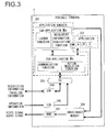
- FIG. 3 is a diagram schematically illustrating the software structure adopted in the portable terminal 2.
- An application manager 201 in FIG. 3 includes a sub-application Ma and a sub-application Ms.
- the sub-application Ma has a launch function for starting up applications other than the application manager 201 itself and a regulatory information acquisition function for obtaining regulatory information for each application.
- the control unit 20 is able to use these functions by executing the sub-application Ma in the foreground.
- the launch function is used to call up another application and have that application executed in the foreground by the control unit 20, instead of the sub-application Ma.
- the regulatory information acquisition function is used to obtain the regulatory information indicating contents of action regulation to be imposed on each application among the plurality of applications stored in the memory unit 24 while the vehicle is in a traveling state from the memory unit 24, an external server or the like.
- the sub-application Ms has a communication function to be engaged when connecting the portable terminal 2 to the in-vehicle device 1 and an action regulation function for imposing action regulation while the vehicle is in the traveling state.
- the control unit 20 is able to use these functions by executing the sub-application Ms in the background.
- the communication function enables execution of communication processing so as to allow the information terminal 2 and the in-vehicle device 1 to exchange information needed for coordinated operations.
- the action regulation function is used to determine the contents of the action regulation to be imposed on the application being executed in the foreground while the vehicle is in a traveling state by referencing the regulatory information obtained through the regulatory information acquisition function of the sub-application Ma described earlier. Restriction information indicating the determination results is transmitted from the portable terminal 2 to the in-vehicle device 1 through the communication function and is utilized in the in-vehicle device 1 when imposing action restriction while the vehicle is in a traveling state.
- the application manager 201 is configured with two separate sub-applications, i.e., the sub-application Ma executed by the control unit 20 in the foreground and the sub-application Ms executed by the control unit 20 in the background.
- optimization of function assignments within the application manager 201 is achieved so as to assign functions best suited for foreground execution as foreground functions and assign functions best suited for background execution as background functions.
- an application that is executed always in the background such as the sub-application Ms is sometimes referred to as a daemon or a service.
- the application manager 201 calls up a given application among various applications 202 through the launch function of the sub-application Ma.
- the application thus called up is then executed by the control unit 20 in the foreground instead of the sub-application Ma. It is to be noted that the following description will be given in reference to FIG. 3 by assuming that application A is being executed.
- An OS (operating system) 203 is a software program used to manage the overall operations of the portable terminal 2.
- the OS 203 acts as a go-between for information output from the sub-application Ms executed by the control unit 20 in the background and input to an SPP (Serial Port Profile) 204 and an HID (Human Interface Device) profile 205 and vice versa.
- SPP Serial Port Profile
- HID Human Interface Device
- the SPP 204 and the HID profile 205 are drivers used in short-range wireless communication carried out between the in-vehicle device 1 and the portable terminal 2. These drivers are standardized as part of the standard used in compliance with Bluetooth.
- the SPP 204 executes processing for transmitting the restriction information indicating the results of the determination made with regard to the action regulation contents through the action regulation function of the sub-application Ms, and processing for receiving traveling information transmitted from the in-vehicle device 1 based upon the vehicle traveling state.
- the HID profile 205 executes processing for receiving operation information output in correspondence to contents of the user operation performed at the in-vehicle device 1.
- the contents of the various types of information received by the SPP 204 and the HID profile 205 are output to the sub-application Ms via the OS 203 and are then transferred to the application, the execution of which is underway, through the communication function of the sub-application Ms. It is to be noted that the transmission/reception of the various types of information is enabled through wireless communication carried out by the short-range wireless communication interface unit 15 at the in-vehicle device 1 and the short-range wireless communication interface unit 25 at the portable terminal 2.
- the sub-application Ma When the sub-application Ma is currently executed in the foreground by the control unit 20, the sub-application Ma generates a menu screen image that will allow the user to select an application he wishes to have executed by the launch function explained earlier. If, on the other hand, an application A is currently being executed in the foreground by the control unit 20, the application A generates a specific image and sound by utilizing, as needed, the traveling information or the operation information transferred from the sub-application Ms. The image and the sound are then stored into an image/audio memory 206 on a temporary basis, before they are output to an HDMI driver 207.
- the HDMI driver 207 executes processing for converting an image and sound generated by the sub-application Ma, application A or the like to a video signal and an audio signal through a method in compliance with the HDMI standard.
- the video signal and the audio signal resulting from the conversion are then output by the video/audio signal output unit 26 to in-vehicle device 1 via the video/audio cable 3.
- the portable terminal 2 has a software structure as described above. It is to be noted that the software structure may be achieved by using, for instance, the Android operating system. In the software configured in the Android operating system, the sub-application Ma will be executed in the "Activity" thread and the sub-application Ma will be executed in the "Service” thread so as to enable execution of the sub-application Ma in the foreground by the control unit 20 concurrently with the sub-application Ms, being executed in the background.
- the HID packet which is a communication format for a mouse used in Bluetooth, are generally used when a mouse is used as an input device of the portable terminal 2.
- displacement quantity information corresponding to the movement of the mouse and button operation information corresponding to various types of button operations, for instance, a click operation in a predetermined format can be transmitted from the mouse to the portable terminal 2 at predetermined time intervals.
- the portable terminal 2 Upon receipt of these pieces of information transmitted from the mouse via the HID packet, the portable terminal 2 performs reception processing through the HID profile 205 shown in FIG. 3 and the OS 203 reads the received information to detect the movement of the mouse and causes the cursor on the screen to be displaced in correspondence to the detected movement of the mouse.
- the OS 203 reads the content of the operation that is performed by the user on the screen based upon the content of the screen corresponding to the cursor position at that time and the content of the button operation.
- an application corresponding to the icon specified on the menu screen in correspondence to the content of the operation of the mouse read by the OS 203 is started up or the processing corresponding to the operation specified on the screen of the application being executed is executed.
- the operation information corresponding to the touch operation at the in-vehicle device 1 is transmitted from the in-vehicle device 1 to the portable terminal 2 by using the HID packet as described above.
- the content of touch operation can be recognized by the OS 203 at the portable terminal 2, similarly to the case in which a mouse is used.
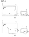
- FIG. 4(a) and FIG. 4(b) are diagrams illustrating the operations of the in-vehicle device 1 and the portable terminal 2, respectively, when the touch operation is performed at the in-vehicle device 1.
- FIG. 4(a) illustrates the condition before the touch operation.
- arrow-shaped cursors 40 brought up on display at respective right lower ends of the outer peripheries of the display units 11 and 21, respectively, have each a tip portion of the arrow, a left upper end of which serves as a point of indication.
- the cursor 40 on the screen indicates a reference position 41 located at a position accounting for the right lower end of the display unit 11 in the in-vehicle device 1 or a reference position 42 located at a position accounting for the right lower end of the display unit 21. It is to be noted that the most part of the cursor 40 is located outside the range of each screen display at the display units 11 and 21 and actually, it is not brought up on display. Therefore, in FIG. 4(a) , the display position of the cursor 40 is shown in broken line.
- the portable terminal 2 brings up at the display unit 21 a screen including the cursor 40 brought up on display at the reference position 42 and at the same time outputs video information of this screen to the in-vehicle device 1 via the video/audio cable 3 by using the video signal described above.
- the in-vehicle device 1 receives the video information from the portable terminal 2, the in-vehicle device 1 brings up on display at the display unit 11 the same screen as that which is brought up on display at the display unit 21 of the portable terminal 2 based upon the video information.
- the screen including the cursor 40 brought up on display at the reference position 41 is displayed at the display unit 11.
- the resolution of the display unit 11 in the X direction is expressed as Xv
- the resolution of the display unit 11 in the Y direction is expressed as Yv
- the resolution of the display unit 21 in the X direction is expressed as Xs
- the resolution of the display unit 21 in the Y direction is expressed as Ys.
- the information about these resolutions is stored in advance in the memory units 14 and 24 at the in-vehicle device 1 and the portable terminal 2, respectively.
- FIG. 4(b) shows the condition when a touch operation is performed. It is assumed that as shown in FIG. 4(b) , the touch operation is performed by the user to the in-vehicle device 1 to specify a touch position 43.
- the in-vehicle device 1 detects this touch operation, it calculates a displacement quantity Px in the X direction and a displacement quantity Py in the Y direction, as quantities of displacement ranging from the reference position 41, which was indicated by the cursor 40 before the touch operation, to the touch position 43.
- the displacement quantities Px and Py can be calculated by, for instance, counting the number of pixels existing between the reference position 41 and the touch position 43 in the X direction and in the Y direction, respectively.
- both the displacement quantities Px and Py between the reference position 41 and the touch position 43 are obtained as negative values.
- the in-vehicle device 1 After the displacement quantity Px in the X direction and the displacement quantity Py in the Y direction are calculated as described above, the in-vehicle device 1 subsequently converts the displacement quantities Px and Py into displacement quantities Qx and Qy, respectively, on the display unit 21 of the portable terminal 2.
- This conversion of displacement quantities is performed based upon the resolutions Xv, Yv and the resolutions Xx, Ys described above according to the following expression (1).
- Qx PxX Xs / Xv
- Qy PyX Ys / Yv
- Xs/Xv and Ys/Yv are conversion coefficients used when the displacement quantities Px and Py are converted into the displacement quantities Qx and Qy, respectively.
- the in-vehicle device 1 is enabled to obtain these conversion coefficients by obtaining the resolutions Xs and Ys of the display unit 21 from the portable terminal 2 in advance.
- the in-vehicle device 1 transmits displacement quantity information indicating the displacement quantities Qx and Qy to the portable terminal 2 according to the HID packet.
- the portable terminal 2 When the portable terminal 2 receives displacement quantity information indicating the displacement quantities Qx and Qy from the in-vehicle device 1, it causes the displacement quantities Qx and Qy to be read by the OS 203. Then, as shown in FIG. 4(b) , it brings up on display, at the display unit 21, the cursor 40 as being displaced by the displacement quantities Qx and Qy from the reference position 42 located at the right lower end at the display unit 21 and at the same time outputs video information of the screen including the cursor 40 thus displaced to the in-vehicle device 1 via the video/audio cable 3 by using the video signal described above.
- the in-vehicle device 1 When the in-vehicle device 1 receives the video information about the screen including the cursor 40 after the displacement from the portable terminal 2, it brings up on display the same screen as that brought up on display at the display unit 21 of the portable terminal 2 at the display unit 11 based upon the received video information. As a result, the screen in which the cursor 40 specifies the touch position 43 is brought up on display at the display unit 11 as shown in FIG. 4(b) .
- the in-vehicle device 1 After having transmitted the displacement quantity information indicating the displacement quantities Qx and Qy, the in-vehicle device 1 transmits displacement quantity information indicating that the displacement quantity is 0 to the portable terminal 2 through the HID packet. On this occasion, additionally, button operation information indicating that a predetermined button operation, for instance, a left click operation has been performed is transmitted together.
- the portable terminal 2 Upon receipt of the displacement quantity information and the button operation information from the in-vehicle device 1, the portable terminal 2 causes the content of the button operation that is indicated by the button operation information to be read by the OS 203. Then, for instance, startup of the application corresponding to the icon at the touch position 43 is performed in correspondence to the content of the screen brought up on display at the display position, that is, the touch position 43, of the cursor 40 after the displacement and the content of the button operation. In the manner as that explained earlier, the processing in correspondence to the touch operation performed by the user to the in-vehicle device 1 can be executed at the portable terminal 2.
- the operation at the time of the touch operation explained above is an example of a single tap operation, which is specified by the user's tapping a given touch position on the touch panel once.
- the in-vehicle device 1 transmits to the portable terminal 2 the same operation information as that transmitted when a click operation is performed with a mouse.
- the user may perform various operations; for instance, a double tap operation in which the touch position is specified by tapping twice, a flick operation in which along with the touch operation, the touch position is displaced in a predetermined direction, a press-and-hold operation in which the same touch position is continued to be touched for a predetermined period of time or longer, and so on may be performed to the in-vehicle device 1.
- the in-vehicle device 1 identifies types of the touch operations, one from another, and transmits to the portable terminal 2 different operation information in correspondence to the respective types of the touch operations.
- the in-vehicle device 1 transmits displacement quantity information indicating the displacement quantities Qx and Qy after conversion in correspondence to the displacement quantities Px and Py and thereafter transmits twice the button operation information indicating a predetermined button operation along with the displacement quantity information indicating that the displacement quantity is 0.
- the in-vehicle device 1 transmits to the portable terminal 2 the same operation information as that transmitted when the double click operation is performed with a mouse.
- the in-vehicle device 1 transmits the displacement quantity information indicating the displacement quantities Qx and Qy after conversion in correspondence to the displacement quantities Px and Py and thereafter calculates the displacement quantity of the touch position during the flick operation at predetermined time intervals. Then, the in-vehicle device 1 converts, according to the expression (1) described above, the displacement quantity of the touch position during the flick operation into the displacement quantity on the display unit 21 of the portable terminal 2 and transmits the displacement quantity information indicating the displacement quantity after the conversion along with the button operation information indicating a predetermined button operation. After the flick operation is completed, the in-vehicle device 1 finally transmits the displacement quantity information indicating that the displacement quantity is 0. In other words, the in-vehicle device 1 transmits to the portable terminal 2 the same operation information as that transmitted when the drag-and-drop operation is performed with a mouse.
- the in-vehicle device 1 transmits the displacement quantity information indicating the displacement quantities Qx and Qy after conversion in correspondence to the displacement quantities Px and Py, respectively, and thereafter continually transmits the button operation information indicating a predetermined button operation along with the displacement quantity information indicating that the displacement quantity is 0 during the press-and-hold operation. That is, the in-vehicle device 1 transmits to the portable terminal 2 the same operation information as that transmitted when press and hold operation is performed with a mouse.
- the portable terminal 2 can identify the type of the touch operation performed by the user to the in-vehicle device 1 and execute the processing corresponding to the touch operation.
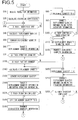
- FIG. 5 presents a flowchart illustrating the processing executed at the in-vehicle device 1 when a touch operation is performed.
- the processing illustrated in this flowchart is to be executed by the control unit 10 once communication is established between the in-vehicle device 1 and the portable terminal 2.
- step S10 the control unit 10 receives the resolution information of the display unit 21 transmitted from the portable terminal 2 by using the short-range wireless communication interface unit 15. In this step, as described earlier, the control unit 10 receives the resolution Xs in the X direction of the display unit 21 and the resolution Ys in the Y direction of the display unit 21 from the portable terminal 2.
- step S20 the control unit 10 calculates a conversion coefficient in correspondence to a ratio of the resolution of the display unit 21 to the resolution of the display unit 11 based upon the resolution information of the display unit 21 received from the portable terminal 2 in step S10 and the resolution of the display unit 11 stored in the memory unit 14 in advance.
- the resolutions Xs and Ys of the display unit 21 shown in the resolution information received in step S10 are divided by the resolution Xv of the display device 11 in the X direction and the resolution Yv of the display unit 11 in the Y direction, respectively, to calculate a conversion coefficient in the X direction, Xx/Xv and a conversion coefficient in the Y direction, Ys/Yv, respectively.
- step S30 the control unit 10 makes a decision as to whether or not a touch operation has been performed by the user to the operation unit 12, which is a touch panel switch that is integrally constituted with the display unit 11. If a touch operation has been performed, the control unit 10 detects the touch operation and the operation proceeds to step S40.
- step S40 the control 10 calculates displacement quantities from the display position of the cursor when the touch operation was detected in step S30 to the touch position specified by that touch operation.
- the control unit 10 calculates the displacement quantity in the X direction, Px, and the displacement quantity in the Y direction, Py, as the displacement quantities from the reference position 41 at the right lower end to the touch position 43.
- step S50 the control unit 10 converts the displacement quantities calculated in step S40 into displacement quantities on the display unit 21 of the portable terminal 2.
- the control unit 10 converts the displacement quantity in the X direction, Px, and the displacement quantity in the Y direction, Py, calculated relative to the display unit 11, the displacement quantities in the X direction, Qx, and the displacement quantity in the Y direction, Qy on the display unit 21 according to the expression (1) described above by using the conversion coefficient in the X direction, Xs/Xv, and the conversion coefficient in the Y direction, Ys/Yv, that have been calculated in step S20.
- step S60 the control unit 10 transmits to the portable terminal 2 the displacement quantity information indicating the displacement quantity converted in step S50 by using the short-range wireless communication interface unit 15.
- displacement quantity information in correspondence to the displacement quantity from the display position of the cursor at the time of the touch operation to the detected touch position is transmitted from the in-vehicle device 1 to the portable terminal 2.
- Transmission of the displacement quantity information is performed by using the HID packet, which is a communication format for a mouse as described above.
- the displacement quantity information transmitted from the in-vehicle device 1 is received by the short-range wireless communication interface unit 25 in the portable terminal 2 and read by the OS 203.
- the cursor position on the screen is displaced at the portable terminal 2 and the video information including the cursor after the displacement is transmitted from the portable terminal 2 to the in-vehicle device 1 and brought up on display on the display unit 11.
- step S70 the control unit 10 makes a decision as to whether or not the touch operation detected in step S30 is going on. If the touch operation is completed within a predetermined period of time, it is decided that the touch operation is not going on and the operation proceeds to step S80, whereas if it is decided that the touch operation is going on, the operation proceeds to step S130.
- step S80 the control unit 10 sets the displacement quantity in the displacement quantity information to 0 in step S80.
- the displacement quantity is set to 0 for both the X direction and the Y direction.
- step S90 the control unit 10 transmits the displacement quantity information indicating that the displacement quantity set in step S80 is 0 and the button operation information indicating that the predetermined button operation such as a left click operation has been performed to the portable terminal 2 via the short-range wireless communication interface unit 15.
- step S100 the control unit 10 makes a decision as to whether or not another touch operation is performed to the operation unit 12, which is a touch panel switch that is integrally constituted with the display unit 11, subsequent to the touch operation detected in step S30. If touch operations are not performed successively, that is, a single tap operation is performed, the operation proceeds to step S110. As a result, if the single tap operation has been performed, the displacement quantity information is transmitted in step S60 and thereafter the processing in step S90 is executed only once, in which along with the displacement quantity information indicating that the displacement quantity is 0, the button operation information is transmitted from the in-vehicle device 1 to the portable terminal 2.
- step S100 if a decision is made that the touch operations have been performed successively in step S100, the operation returns to step S90 and the processing in step S90 is repeatedly executed the number of times in which the touch operations occurred.
- the displacement quantity information is transmitted in step S60 and thereafter, the processing in step S90 is executed twice, so that along with the displacement quantity information indicating that the displacement quantity is 0, the button operation information is transmitted twice from the in-vehicle device 1 to the portable terminal 2.
- the third or subsequent touch operations may be invalidated in order to treat the three or more touch operations as a double tap operation.
- a configuration may be adopted in which the displacement quantity information and the button operation information are transmitted three or more times successively by repeatedly executing the processing in step S90 as many times as that in which the touch operations have been performed.
- step S110 the control unit 10 sets a predetermined maximal value of displacement quantity in the displacement quantity information.
- a predetermined maximal displacement quantity is set for both the X and Y directions.
- step S120 the control unit 10 transmits the displacement quantity information indicating the maximal displacement quantity set in step S110 to the portable terminal 2 via the short-range wireless communication interface unit 15. If the processing in step S120 is executed, the operation returns to step S30 and the processing as described above is repeated.
- the displacement quantity information indicating the maximal displacement quantity transmitted in step S120 is received by the short-range wireless communication interface unit 25 at the portable terminal 2 and read by the OS 203. Then, the display position of the cursor on the screen at the display unit 21 is displaced to maximal positions in the X and Y positions, that is, to the reference position 42 at the right lower end shown in FIGS. 4(a) and 4(b) regardless of the touch position specified by lastly performed touch operation relative to the in-vehicle device 1.
- the display position of the cursor on the screen at the display unit 11 in the in-vehicle device 1 is returned back to the original reference position 41.
- step S130 the control unit 10 in step S130 makes a decision as to whether or not the touch position has been changed by the touch operation detected in step S30. If it is decided that the touch position has been changed, the operation proceeds to step S140. If, on the other hand, it is decided that the touch position has not been changed, the operation proceeds to step S200.
- step S140 the control unit 10 in step S140 calculates the displacement quantity from the last touch position to the present touch position. Subsequently, in step S150, the control unit 10 converts the displacement quantity calculated in step S140 to displacement quantity on the display unit 21 of the portable terminal 2.
- step S160 the control unit 10 transmits the displacement quantity information indicating the displacement quantity converted in step S150 and the button operation information indicating that the predetermined button operation such as a left click operation has been performed to the portable terminal 2 via the short-range wireless communication interface unit 15.
- the displacement quantity information indicating the displacement quantity in correspondence to the change in the touch position and the button operation information are transmitted from the in-vehicle device 1 to the portable terminal 2.
- the transmitted displacement quantity information here is received by the short-range wireless communication interface unit 25 in the portable terminal 2 and read by the OS 203.
- the cursor position on the screen at the portable terminal 2 is displaced in correspondence to the change in touch position at the in-vehicle device 1 and the video information including the cursor after the displacement is transmitted from the portable terminal 2 to the in-vehicle device 1 and brought up on display at the display unit 11.
- step S170 the control unit 10 makes a decision as to whether or not the touch operation is completed. If the touch operation is going on, the operation returns to step S140 and the processing in steps S140 through S160 is repeated. Through these measures, if a flick operation, in which the touch position is changed while the touch operation is going on, has been performed, and if the touch operation is going on after the displacement quantity information has been transmitted in step S60, the displacement quantity information indicating the displacement quantity in correspondence to the change in the touch position and the button operation information are transmitted continuously. If the touch operation is completed, the operation proceeds to step S180.
- step S180 the control unit 10 sets the displacement quantity in the displacement quantity information to 0 in the same manner as that in step S80 described above. Subsequently, in step S190, the control unit 10 transmits the displacement quantity information indicating that the displacement quantity set in step S180 is 0 to the portable terminal 2 via the short-range wireless communication interface unit 15. Through this measure, if the flick operation has been performed and after the touch operation has been completed, the displacement quantity information indicating that the displacement quantity is 0 is transmitted from the in-vehicle device 1 to the portable terminal 2.
- step S190 the control unit 10 causes the display position of the cursor on the screen at the display unit 11 to be returned back to the original reference position 41 by executing each processing in steps S110 and S120 described above. Thereafter, the operation returns to step S30 and the processing as described above is repeated.
- step S200 sets the displacement quantity in the displacement quantity information to 0 in the same manner as that in steps S80 and S180 described above. Subsequently in step S210, the control unit 10 transmits the displacement quantity information indicating that the displacement quantity set in step S200 is 0 and the button operation information indicating that a predetermined button operation such as a left click operation has been performed to the portable terminal 2 via the short-range wireless communication interface unit 15.
- step S220 the control unit 10 makes a decision as to whether or not the touch operation is completed. If the touch operation is going on, the operation returns to step S210 and the processing in step S210 is repeated. Through this measure, if a press-and-hold operation, in which a touch operation is going on for a predetermined period of time or longer with the touch position being unchanged, has been performed and if the touch operation is going on after the displacement quantity information has been transmitted in step S60, the button operation information along with the displacement quantity information indicating that the displacement quantity is 0 is continuously transmitted. If the touch operation is completed, the control unit 10 causes the display position of the cursor on the screen at the display unit 11 to be returned to the original reference position 41 by executing each processing in steps S110 and S120. Thereafter, the operation returns to step S30 and the processing described above is repeated.
- the embodiment explained earlier relates to an example in which when no touch operation is performed, the cursor 40 is brought up on display at the reference positions 41 and 42 each located at the right lower ends of the display units 11 and 12, respectively.
- the cursor 40 may be brought up on display at a position other than the above reference positions.
- the cursor 40 is enabled to be arranged so that it will not be unpleasant to the eye of the user in the same manner as that in the embodiment described above even if the cursor 40 is brought up on display at any desired position when no touch operation is performed.
- the reference position 41 is set at the right lower end in an orientation opposite to the orientation toward the left upper orientation, which is directed from the central point of the cursor 40 to the point of indication.
- the embodiment explained earlier relates to an example, in which after completion of the touch operation in step S120 shown in FIG. 5 , the displacement quantity information indicating the predetermined maximal displacement quantity for each of the transverse direction (X direction) and the longitudinal direction (Y direction) of the display unit 11 is transmitted to the portable terminal 2 to cause the display position of the cursor 40 to be returned to the original reference position 41.
- the left upper end of the display unit 11 is defined to be a start point
- the right direction is defined to be a positive orientation of the X direction
- the lower direction is defined to be a positive orientation of the Y direction
- this measure is effective for causing the cursor 40 to be returned to the reference position 41 at the right lower end of the display unit 11.
- step S120 after completion of the touch operation, the displacement quantity information indicating the predetermined maximal displacement quantity or the predetermined minimal displacement quantity in correspondence to the position of the start point and the definitions of the positive orientations of the X and Y directions, respectively, relative to the transverse direction (X direction) and the longitudinal direction (Y direction) may be transmitted to the portable terminal 2 in order to cause the display position of the cursor 40 to be returned to the reference position 41. It is to be noted that the same is true when the right lower end of the display 11 is taken as the reference position.
- communication between the in-vehicle device 1 and the portable terminal 2 may be carried out through wired communication such as USB communication.
- wired communication such as USB communication.
- the displacement quantity information and the button operation information can be transmitted from the in-vehicle device 1 to the portable terminal 2 by using the communication format for USB or the like instead of the HID packet described earlier.
- Any communication method may be adopted in the present invention as long as it allows the in-vehicle device 1 and the portable terminal 2 to exchange necessary signals and information.
- various types of vehicle information output from the vehicle other than the vehicle speed signal and the parking signal may also be obtained by the in-vehicle device 1.
- vehicle information taken into the in-vehicle device 1 may then be utilized in the processing executed in the in-vehicle device 1, or it may be output from the in-vehicle device 1 to the portable terminal 2 and used in the processing executed at the portable terminal 2.
- a configuration may be adopted in which a start-up condition in correspondence to such vehicle information may be set in advance for each application and when the vehicle information indicating a specific start-up condition is output from the vehicle, the corresponding application may be started up automatically at the portable terminal 2.
- the information indicating the start-up conditions for the individual applications may be transmitted from the portable terminal 2 to the in-vehicle device 1 and a decision as to whether or not a start-up condition exists may be made in the in-vehicle device 1 based upon the vehicle information.
- the vehicle information may be transmitted from the in-vehicle device 1 to the portable terminal 2 and the decision as to whether or not a start-up condition exists may be made at the portable terminal 2 based upon the vehicle information.
- vehicle information makes it possible for the portable terminal 2 to automatically start-up an application that, for instance, enables a search for gas stations located near the current position when vehicle information, indicating that the quantity of remaining fuel in the vehicle has become less than a predetermined quantity, is output from the vehicle.
- the example is explained in which a touch panel is adopted as the display unit 11 of the in-vehicle device 1 and an image received from the portable terminal 2 is brought up on display at the display unit 11.
- the present invention is not limited to this example.
- the present invention can be adopted in any display device as far as it can be connected with an information terminal and brings up on display an image received from the information terminal on a touch panel.
- 1 in-vehicle device, 2: portable terminal, 3: video/audio cable, 10: control unit, 11: display unit, 12: operation unit, 13: audio output unit, 14: memory unit, 15: short-range wireless communication interface unit, 16:vide/audio signal input unit, 20: control unit, 21: display unit, 22: operation unit, 23: audio output unit, 24: memory unit, 25: short-range wireless communication interface unit, 26:video/audio signal output unit, 27: wireless communication unit, 28: GPS receiver unit.
Landscapes
- Engineering & Computer Science (AREA)
- Theoretical Computer Science (AREA)
- General Engineering & Computer Science (AREA)
- Human Computer Interaction (AREA)
- Physics & Mathematics (AREA)
- General Physics & Mathematics (AREA)
- Computer Networks & Wireless Communication (AREA)
- Signal Processing (AREA)
- Mechanical Engineering (AREA)
- Transportation (AREA)
- Combustion & Propulsion (AREA)
- Chemical & Material Sciences (AREA)
- Computer Hardware Design (AREA)
- Multimedia (AREA)
- Navigation (AREA)
- Position Input By Displaying (AREA)
- User Interface Of Digital Computer (AREA)
Applications Claiming Priority (3)
| Application Number | Priority Date | Filing Date | Title |
|---|---|---|---|
| JP2012130929A JP6124169B2 (ja) | 2012-06-08 | 2012-06-08 | 表示装置 |
| PCT/JP2013/065849 WO2013183765A1 (ja) | 2012-06-08 | 2013-06-07 | 表示装置 |
| EP13799850.6A EP2860615B1 (de) | 2012-06-08 | 2013-06-07 | Anzeigevorrichtung |
Related Parent Applications (2)
| Application Number | Title | Priority Date | Filing Date |
|---|---|---|---|
| EP13799850.6A Division EP2860615B1 (de) | 2012-06-08 | 2013-06-07 | Anzeigevorrichtung |
| EP13799850.6A Division-Into EP2860615B1 (de) | 2012-06-08 | 2013-06-07 | Anzeigevorrichtung |
Publications (1)
| Publication Number | Publication Date |
|---|---|
| EP3553639A1 true EP3553639A1 (de) | 2019-10-16 |
Family
ID=49712151
Family Applications (2)
| Application Number | Title | Priority Date | Filing Date |
|---|---|---|---|
| EP13799850.6A Active EP2860615B1 (de) | 2012-06-08 | 2013-06-07 | Anzeigevorrichtung |
| EP19171352.8A Withdrawn EP3553639A1 (de) | 2012-06-08 | 2013-06-07 | Anzeigevorrichtung |
Family Applications Before (1)
| Application Number | Title | Priority Date | Filing Date |
|---|---|---|---|
| EP13799850.6A Active EP2860615B1 (de) | 2012-06-08 | 2013-06-07 | Anzeigevorrichtung |
Country Status (5)
| Country | Link |
|---|---|
| US (2) | US9613593B2 (de) |
| EP (2) | EP2860615B1 (de) |
| JP (1) | JP6124169B2 (de) |
| CN (2) | CN104335148B (de) |
| WO (1) | WO2013183765A1 (de) |
Families Citing this family (24)
| Publication number | Priority date | Publication date | Assignee | Title |
|---|---|---|---|---|
| WO2014098164A1 (ja) * | 2012-12-21 | 2014-06-26 | 日本電気株式会社 | 画像表示装置、携帯端末装置、情報処理システム、画像表示装置制御方法及びプログラム |
| EP2975829B1 (de) * | 2013-03-13 | 2022-02-09 | Clarion Co., Ltd. | Anzeigevorrichtung |
| JP6047822B2 (ja) * | 2013-03-14 | 2016-12-21 | シャープ株式会社 | 情報処理装置、情報処理方法及びプログラム |
| US9937416B2 (en) * | 2013-06-11 | 2018-04-10 | Microsoft Technology Licensing, Llc | Adaptive touch input controls |
| JPWO2015097892A1 (ja) * | 2013-12-27 | 2017-03-23 | パイオニア株式会社 | 端末装置、キャリブレーション方法及びキャリブレーションプログラム |
| JP2015128918A (ja) * | 2014-01-06 | 2015-07-16 | 株式会社東海理化電機製作所 | 操作装置 |
| KR101624180B1 (ko) * | 2014-12-09 | 2016-05-25 | 현대자동차주식회사 | 단말기, 그를 가지는 차량 및 그의 제어 방법 |
| CN104679469B (zh) * | 2014-12-29 | 2019-02-26 | 合肥杰发科技有限公司 | 车载终端及其获取手持终端的屏幕分辨率的方法 |
| CN104657211A (zh) * | 2015-02-03 | 2015-05-27 | 百度在线网络技术(北京)有限公司 | 一种用于操作对应设备上目标应用的方法与设备 |
| GB2536253B (en) * | 2015-03-10 | 2018-12-19 | Displaylink Uk Ltd | System for connecting external displays to a mobile device |
| CN105045692B (zh) * | 2015-07-22 | 2018-11-30 | 京东方科技集团股份有限公司 | 触摸屏测试装置及系统、触摸屏测试控制装置 |
| CN105260112A (zh) * | 2015-09-14 | 2016-01-20 | 百度在线网络技术(北京)有限公司 | 终端间屏幕控制的方法和装置 |
| CN107025894A (zh) * | 2016-02-02 | 2017-08-08 | 上海嘉车信息科技有限公司 | 车载屏幕亮度及内容显示自适应的控制系统及控制方法 |
| JP6686689B2 (ja) * | 2016-05-13 | 2020-04-22 | 三菱自動車工業株式会社 | 車両制御システム |
| US11067978B2 (en) | 2016-12-19 | 2021-07-20 | Clarion Co., Ltd. | Terminal and method for controlling terminal |
| JP6397530B2 (ja) * | 2017-03-24 | 2018-09-26 | クラリオン株式会社 | 表示装置 |
| JP2018194584A (ja) * | 2017-05-12 | 2018-12-06 | シャープ株式会社 | 表示装置、表示装置における情報端末機の設定方法および表示システム |
| JP2018081711A (ja) * | 2017-12-25 | 2018-05-24 | パイオニア株式会社 | 端末装置、キャリブレーション方法及びキャリブレーションプログラム |
| JP7059715B2 (ja) * | 2018-03-15 | 2022-04-26 | 京セラドキュメントソリューションズ株式会社 | 画像形成装置、画像形成システム |
| CN109561202B (zh) * | 2018-09-29 | 2021-10-08 | 百度在线网络技术(北京)有限公司 | 控件处理方法、装置、终端设备、车机及系统 |
| JP2019179563A (ja) * | 2019-06-04 | 2019-10-17 | パイオニア株式会社 | 端末装置 |
| TWI801867B (zh) * | 2021-05-12 | 2023-05-11 | 虹堡科技股份有限公司 | 密碼輸入裝置 |
| CN113282340B (zh) * | 2021-05-12 | 2023-04-07 | 聚融医疗科技(杭州)有限公司 | 用于带触摸屏的多屏超声诊疗系统的鼠标管理方法及装置 |
| US20230063335A1 (en) * | 2021-08-27 | 2023-03-02 | Ricoh Company, Ltd. | Display apparatus, display system, display control method, and non-transitory recording medium |
Citations (6)
| Publication number | Priority date | Publication date | Assignee | Title |
|---|---|---|---|---|
| JP2003244343A (ja) | 2002-02-21 | 2003-08-29 | Toyota Motor Corp | 表示装置、携帯端末及び情報表示システム |
| US20080158170A1 (en) * | 2007-01-03 | 2008-07-03 | Apple Computer, Inc. | Multi-event input system |
| US20080158152A1 (en) * | 2006-12-27 | 2008-07-03 | Lenovo (Singapore) Pte. Ltd. | Cursor jump control with a touchpad |
| US20110128446A1 (en) * | 2009-11-27 | 2011-06-02 | Hyundai Motor Company | Car audio/video terminal system having user interface linkable with portable device and method for linking the same |
| US7970436B1 (en) * | 2006-09-22 | 2011-06-28 | Sprint Communications Company L.P. | Wireless interface extension for mobile devices |
| JP2012130929A (ja) | 2010-12-20 | 2012-07-12 | Mitsubishi Heavy Ind Ltd | バックシール施行用装置 |
Family Cites Families (33)
| Publication number | Priority date | Publication date | Assignee | Title |
|---|---|---|---|---|
| US4216352A (en) * | 1978-11-02 | 1980-08-05 | The Charles Stark Draper Laboratory, Inc. | Two coordinate position sensing systems |
| US5274794A (en) * | 1991-01-22 | 1993-12-28 | Graphon Corporation | Method and apparatus for transferring coordinate data between a host computer and display device |
| JPH09244809A (ja) | 1996-03-06 | 1997-09-19 | Nec Eng Ltd | マウス透過式タッチパネル装置 |
| US6952799B2 (en) * | 1996-06-17 | 2005-10-04 | British Telecommunications | User interface for network browser including pre-processor for links embedded in hypermedia documents |
| US6750803B2 (en) * | 2001-02-23 | 2004-06-15 | Interlink Electronics, Inc. | Transformer remote control |
| KR100474724B1 (ko) | 2001-08-04 | 2005-03-08 | 삼성전자주식회사 | 터치스크린을 가지는 장치 및 그 장치에 외부디스플레이기기를 연결하여 사용하는 방법 |
| US20030231168A1 (en) * | 2002-06-18 | 2003-12-18 | Jory Bell | Component for use as a portable computing device and pointing device in a modular computing system |
| JP2005056088A (ja) | 2003-08-01 | 2005-03-03 | Ricoh Co Ltd | タッチパネル付きディスプレイ装置、タッチパネル付きディスプレイ装置の制御方法およびその方法をコンピュータに実行させるためのプログラム |
| DE102005023544A1 (de) * | 2005-05-21 | 2006-12-07 | Bayerische Motoren Werke Ag | Anschluss von persönlichen Endgeräten an das Kommunikationssystem eines Kraftfahrzeuges |
| TWI284274B (en) * | 2005-06-29 | 2007-07-21 | Elan Microelectronics Corp | Method for controlling intelligent movement of touch pad |
| US20090195513A1 (en) * | 2008-02-05 | 2009-08-06 | Delphi Technologies, Inc. | Interactive multimedia control module |
| US8085281B2 (en) * | 2008-05-08 | 2011-12-27 | Microsoft Corporation | Method of displaying input from a portable computing device |
| CN102197358A (zh) * | 2008-10-28 | 2011-09-21 | 夏普株式会社 | 具有2个显示装置的电子设备、其控制方法以及记录介质 |
| US20100220066A1 (en) * | 2009-02-27 | 2010-09-02 | Murphy Kenneth M T | Handheld electronic device having a touchscreen and a method of using a touchscreen of a handheld electronic device |
| US9258402B2 (en) * | 2009-04-14 | 2016-02-09 | Qualcomm Incorporated | System and method for controlling mobile devices |
| TW201104529A (en) * | 2009-07-22 | 2011-02-01 | Elan Microelectronics Corp | Touch device, control method and control unit for multi-touch environment |
| CN101667079A (zh) * | 2009-09-16 | 2010-03-10 | 中兴通讯股份有限公司南京分公司 | 通过移动终端触摸屏控制计算机的方法、系统及移动终端 |
| CN101674671B (zh) * | 2009-10-13 | 2012-02-01 | 武汉市城市规划设计研究院 | 基于移动互联网络的规划信息处理和发布方法及其系统 |
| US8694177B2 (en) * | 2010-03-12 | 2014-04-08 | GM Global Technology Operations LLC | Flexible vehicle display |
| TWM389063U (en) | 2010-03-16 | 2010-09-21 | Wonde Proud Technology Co Ltd | Vehicle mobile device control system |
| TWI529574B (zh) * | 2010-05-28 | 2016-04-11 | 仁寶電腦工業股份有限公司 | 電子裝置與其操作方法 |
| JP2011254238A (ja) * | 2010-06-01 | 2011-12-15 | Sony Corp | 情報処理装置、情報処理方法および情報処理システム |
| JP5517761B2 (ja) * | 2010-06-10 | 2014-06-11 | アルパイン株式会社 | 電子機器および操作キーの割当方法 |
| JP5527064B2 (ja) * | 2010-07-09 | 2014-06-18 | トヨタ自動車株式会社 | 画像表示システム |
| JP2012058857A (ja) * | 2010-09-06 | 2012-03-22 | Sony Corp | 情報処理装置、操作方法及び情報処理プログラム |
| CN101937312B (zh) * | 2010-09-15 | 2014-03-19 | 中兴通讯股份有限公司 | 一种电子书的标记方法及移动终端 |
| CN103118904B (zh) * | 2010-09-17 | 2015-10-07 | 歌乐株式会社 | 车载信息系统、车载装置、信息终端 |
| US20120075204A1 (en) * | 2010-09-27 | 2012-03-29 | Google Inc. | Using a Touch-Sensitive Display of a Mobile Device with a Host Computer |
| JP2012236327A (ja) * | 2011-05-11 | 2012-12-06 | Canon Inc | 印刷装置、印刷装置の制御方法、及びプログラム |
| JP5259772B2 (ja) * | 2011-05-27 | 2013-08-07 | 株式会社東芝 | 電子機器、操作支援方法及びプログラム |
| CN102314502B (zh) * | 2011-09-01 | 2017-03-01 | 百度在线网络技术(北京)有限公司 | 一种用于在移动终端上显示网页主体内容的方法和设备 |
| KR20130053185A (ko) * | 2011-11-15 | 2013-05-23 | 삼성전자주식회사 | 전자기기들 간의 상호 제어 방법 및 시스템 |
| WO2013121455A1 (ja) * | 2012-02-13 | 2013-08-22 | 日立コンシューマエレクトロニクス株式会社 | プロジェクタ、図形入力・表示装置、携帯端末およびプログラム。 |
-
2012
- 2012-06-08 JP JP2012130929A patent/JP6124169B2/ja active Active
-
2013
- 2013-06-07 WO PCT/JP2013/065849 patent/WO2013183765A1/ja active Application Filing
- 2013-06-07 CN CN201380030082.8A patent/CN104335148B/zh active Active
- 2013-06-07 EP EP13799850.6A patent/EP2860615B1/de active Active
- 2013-06-07 CN CN201710920254.9A patent/CN107621923B/zh active Active
- 2013-06-07 EP EP19171352.8A patent/EP3553639A1/de not_active Withdrawn
- 2013-06-07 US US14/406,055 patent/US9613593B2/en active Active
-
2017
- 2017-02-22 US US15/439,030 patent/US10528311B2/en active Active
Patent Citations (6)
| Publication number | Priority date | Publication date | Assignee | Title |
|---|---|---|---|---|
| JP2003244343A (ja) | 2002-02-21 | 2003-08-29 | Toyota Motor Corp | 表示装置、携帯端末及び情報表示システム |
| US7970436B1 (en) * | 2006-09-22 | 2011-06-28 | Sprint Communications Company L.P. | Wireless interface extension for mobile devices |
| US20080158152A1 (en) * | 2006-12-27 | 2008-07-03 | Lenovo (Singapore) Pte. Ltd. | Cursor jump control with a touchpad |
| US20080158170A1 (en) * | 2007-01-03 | 2008-07-03 | Apple Computer, Inc. | Multi-event input system |
| US20110128446A1 (en) * | 2009-11-27 | 2011-06-02 | Hyundai Motor Company | Car audio/video terminal system having user interface linkable with portable device and method for linking the same |
| JP2012130929A (ja) | 2010-12-20 | 2012-07-12 | Mitsubishi Heavy Ind Ltd | バックシール施行用装置 |
Also Published As
| Publication number | Publication date |
|---|---|
| CN104335148A (zh) | 2015-02-04 |
| US9613593B2 (en) | 2017-04-04 |
| EP2860615A4 (de) | 2016-07-06 |
| JP2013254435A (ja) | 2013-12-19 |
| CN107621923B (zh) | 2021-05-04 |
| US10528311B2 (en) | 2020-01-07 |
| WO2013183765A1 (ja) | 2013-12-12 |
| US20150154728A1 (en) | 2015-06-04 |
| US20170161005A1 (en) | 2017-06-08 |
| CN107621923A (zh) | 2018-01-23 |
| EP2860615B1 (de) | 2019-06-05 |
| EP2860615A1 (de) | 2015-04-15 |
| JP6124169B2 (ja) | 2017-05-10 |
| CN104335148B (zh) | 2017-10-31 |
Similar Documents
| Publication | Publication Date | Title |
|---|---|---|
| US10528311B2 (en) | Display device | |
| US9846506B2 (en) | Display device | |
| US9244696B2 (en) | In-car information system, information terminal, and application execution method | |
| JP6218201B2 (ja) | メニュー画面表示方法、車載装置 | |
| EP2857265B1 (de) | Fahrzeuginternes informationssystem, informationsendgerät und anwendungsausführungsverfahren | |
| US9285963B2 (en) | In-car information system, information terminal, and application execution method | |
| JP6557457B2 (ja) | 画像表示システム、画像表示方法、及び表示装置 | |
| JP6397530B2 (ja) | 表示装置 | |
| JP2015148831A (ja) | 車載情報システム、情報端末、アプリケーション実行方法 | |
| JP2012063249A (ja) | 車載情報システム、車載装置、情報端末 |
Legal Events
| Date | Code | Title | Description |
|---|---|---|---|
| PUAI | Public reference made under article 153(3) epc to a published international application that has entered the european phase |
Free format text: ORIGINAL CODE: 0009012 |
|
| 17P | Request for examination filed |
Effective date: 20190523 |
|
| AC | Divisional application: reference to earlier application |
Ref document number: 2860615 Country of ref document: EP Kind code of ref document: P |
|
| AK | Designated contracting states |
Kind code of ref document: A1 Designated state(s): AL AT BE BG CH CY CZ DE DK EE ES FI FR GB GR HR HU IE IS IT LI LT LU LV MC MK MT NL NO PL PT RO RS SE SI SK SM TR |
|
| STAA | Information on the status of an ep patent application or granted ep patent |
Free format text: STATUS: THE APPLICATION IS DEEMED TO BE WITHDRAWN |
|
| 18D | Application deemed to be withdrawn |
Effective date: 20200603 |