EP3553613A1 - Information processing method, information processing system, and information processing device - Google Patents
Information processing method, information processing system, and information processing device Download PDFInfo
- Publication number
- EP3553613A1 EP3553613A1 EP17878001.1A EP17878001A EP3553613A1 EP 3553613 A1 EP3553613 A1 EP 3553613A1 EP 17878001 A EP17878001 A EP 17878001A EP 3553613 A1 EP3553613 A1 EP 3553613A1
- Authority
- EP
- European Patent Office
- Prior art keywords
- machine tool
- information
- information processing
- machine tools
- machine
- Prior art date
- Legal status (The legal status is an assumption and is not a legal conclusion. Google has not performed a legal analysis and makes no representation as to the accuracy of the status listed.)
- Granted
Links
- 230000010365 information processing Effects 0.000 title claims abstract description 283
- 238000003672 processing method Methods 0.000 title claims abstract description 36
- 238000000034 method Methods 0.000 claims description 71
- 238000004891 communication Methods 0.000 claims description 39
- 238000012937 correction Methods 0.000 claims description 37
- 238000003745 diagnosis Methods 0.000 claims description 20
- 230000006870 function Effects 0.000 claims description 12
- 102220470087 Ribonucleoside-diphosphate reductase subunit M2_S20A_mutation Human genes 0.000 abstract description 3
- 238000010586 diagram Methods 0.000 description 38
- 230000008569 process Effects 0.000 description 36
- 230000001133 acceleration Effects 0.000 description 22
- 238000010801 machine learning Methods 0.000 description 21
- 238000012423 maintenance Methods 0.000 description 15
- 238000012545 processing Methods 0.000 description 14
- 230000004044 response Effects 0.000 description 7
- 239000002826 coolant Substances 0.000 description 6
- 238000007726 management method Methods 0.000 description 6
- 230000015654 memory Effects 0.000 description 5
- 230000003449 preventive effect Effects 0.000 description 5
- 230000005540 biological transmission Effects 0.000 description 4
- 238000002405 diagnostic procedure Methods 0.000 description 4
- 239000012535 impurity Substances 0.000 description 4
- 238000013024 troubleshooting Methods 0.000 description 4
- 238000005259 measurement Methods 0.000 description 3
- 238000012986 modification Methods 0.000 description 3
- 230000004048 modification Effects 0.000 description 3
- 238000012544 monitoring process Methods 0.000 description 3
- 238000013528 artificial neural network Methods 0.000 description 2
- 239000004973 liquid crystal related substance Substances 0.000 description 2
- 238000003754 machining Methods 0.000 description 2
- 230000010355 oscillation Effects 0.000 description 2
- 239000000523 sample Substances 0.000 description 2
- 238000012706 support-vector machine Methods 0.000 description 2
- 230000003936 working memory Effects 0.000 description 2
- 230000008859 change Effects 0.000 description 1
- 238000011109 contamination Methods 0.000 description 1
- 238000007418 data mining Methods 0.000 description 1
- 230000007547 defect Effects 0.000 description 1
- 230000006866 deterioration Effects 0.000 description 1
- 230000000694 effects Effects 0.000 description 1
- 238000005516 engineering process Methods 0.000 description 1
- 239000000463 material Substances 0.000 description 1
- 230000000737 periodic effect Effects 0.000 description 1
- 238000004092 self-diagnosis Methods 0.000 description 1
Images


Classifications
-
- B—PERFORMING OPERATIONS; TRANSPORTING
- B23—MACHINE TOOLS; METAL-WORKING NOT OTHERWISE PROVIDED FOR
- B23Q—DETAILS, COMPONENTS, OR ACCESSORIES FOR MACHINE TOOLS, e.g. ARRANGEMENTS FOR COPYING OR CONTROLLING; MACHINE TOOLS IN GENERAL CHARACTERISED BY THE CONSTRUCTION OF PARTICULAR DETAILS OR COMPONENTS; COMBINATIONS OR ASSOCIATIONS OF METAL-WORKING MACHINES, NOT DIRECTED TO A PARTICULAR RESULT
- B23Q17/00—Arrangements for observing, indicating or measuring on machine tools
- B23Q17/09—Arrangements for observing, indicating or measuring on machine tools for indicating or measuring cutting pressure or for determining cutting-tool condition, e.g. cutting ability, load on tool
- B23Q17/0995—Tool life management
-
- G—PHYSICS
- G05—CONTROLLING; REGULATING
- G05B—CONTROL OR REGULATING SYSTEMS IN GENERAL; FUNCTIONAL ELEMENTS OF SUCH SYSTEMS; MONITORING OR TESTING ARRANGEMENTS FOR SUCH SYSTEMS OR ELEMENTS
- G05B23/00—Testing or monitoring of control systems or parts thereof
- G05B23/02—Electric testing or monitoring
- G05B23/0205—Electric testing or monitoring by means of a monitoring system capable of detecting and responding to faults
- G05B23/0259—Electric testing or monitoring by means of a monitoring system capable of detecting and responding to faults characterized by the response to fault detection
- G05B23/0283—Predictive maintenance, e.g. involving the monitoring of a system and, based on the monitoring results, taking decisions on the maintenance schedule of the monitored system; Estimating remaining useful life [RUL]
-
- B—PERFORMING OPERATIONS; TRANSPORTING
- B23—MACHINE TOOLS; METAL-WORKING NOT OTHERWISE PROVIDED FOR
- B23Q—DETAILS, COMPONENTS, OR ACCESSORIES FOR MACHINE TOOLS, e.g. ARRANGEMENTS FOR COPYING OR CONTROLLING; MACHINE TOOLS IN GENERAL CHARACTERISED BY THE CONSTRUCTION OF PARTICULAR DETAILS OR COMPONENTS; COMBINATIONS OR ASSOCIATIONS OF METAL-WORKING MACHINES, NOT DIRECTED TO A PARTICULAR RESULT
- B23Q17/00—Arrangements for observing, indicating or measuring on machine tools
- B23Q17/09—Arrangements for observing, indicating or measuring on machine tools for indicating or measuring cutting pressure or for determining cutting-tool condition, e.g. cutting ability, load on tool
-
- G—PHYSICS
- G05—CONTROLLING; REGULATING
- G05B—CONTROL OR REGULATING SYSTEMS IN GENERAL; FUNCTIONAL ELEMENTS OF SUCH SYSTEMS; MONITORING OR TESTING ARRANGEMENTS FOR SUCH SYSTEMS OR ELEMENTS
- G05B13/00—Adaptive control systems, i.e. systems automatically adjusting themselves to have a performance which is optimum according to some preassigned criterion
- G05B13/02—Adaptive control systems, i.e. systems automatically adjusting themselves to have a performance which is optimum according to some preassigned criterion electric
- G05B13/0205—Adaptive control systems, i.e. systems automatically adjusting themselves to have a performance which is optimum according to some preassigned criterion electric not using a model or a simulator of the controlled system
- G05B13/024—Adaptive control systems, i.e. systems automatically adjusting themselves to have a performance which is optimum according to some preassigned criterion electric not using a model or a simulator of the controlled system in which a parameter or coefficient is automatically adjusted to optimise the performance
-
- G—PHYSICS
- G05—CONTROLLING; REGULATING
- G05B—CONTROL OR REGULATING SYSTEMS IN GENERAL; FUNCTIONAL ELEMENTS OF SUCH SYSTEMS; MONITORING OR TESTING ARRANGEMENTS FOR SUCH SYSTEMS OR ELEMENTS
- G05B13/00—Adaptive control systems, i.e. systems automatically adjusting themselves to have a performance which is optimum according to some preassigned criterion
- G05B13/02—Adaptive control systems, i.e. systems automatically adjusting themselves to have a performance which is optimum according to some preassigned criterion electric
- G05B13/0265—Adaptive control systems, i.e. systems automatically adjusting themselves to have a performance which is optimum according to some preassigned criterion electric the criterion being a learning criterion
-
- G—PHYSICS
- G05—CONTROLLING; REGULATING
- G05B—CONTROL OR REGULATING SYSTEMS IN GENERAL; FUNCTIONAL ELEMENTS OF SUCH SYSTEMS; MONITORING OR TESTING ARRANGEMENTS FOR SUCH SYSTEMS OR ELEMENTS
- G05B19/00—Programme-control systems
- G05B19/02—Programme-control systems electric
- G05B19/18—Numerical control [NC], i.e. automatically operating machines, in particular machine tools, e.g. in a manufacturing environment, so as to execute positioning, movement or co-ordinated operations by means of programme data in numerical form
- G05B19/406—Numerical control [NC], i.e. automatically operating machines, in particular machine tools, e.g. in a manufacturing environment, so as to execute positioning, movement or co-ordinated operations by means of programme data in numerical form characterised by monitoring or safety
- G05B19/4065—Monitoring tool breakage, life or condition
-
- G—PHYSICS
- G05—CONTROLLING; REGULATING
- G05B—CONTROL OR REGULATING SYSTEMS IN GENERAL; FUNCTIONAL ELEMENTS OF SUCH SYSTEMS; MONITORING OR TESTING ARRANGEMENTS FOR SUCH SYSTEMS OR ELEMENTS
- G05B19/00—Programme-control systems
- G05B19/02—Programme-control systems electric
- G05B19/418—Total factory control, i.e. centrally controlling a plurality of machines, e.g. direct or distributed numerical control [DNC], flexible manufacturing systems [FMS], integrated manufacturing systems [IMS] or computer integrated manufacturing [CIM]
- G05B19/4184—Total factory control, i.e. centrally controlling a plurality of machines, e.g. direct or distributed numerical control [DNC], flexible manufacturing systems [FMS], integrated manufacturing systems [IMS] or computer integrated manufacturing [CIM] characterised by fault tolerance, reliability of production system
-
- G—PHYSICS
- G05—CONTROLLING; REGULATING
- G05B—CONTROL OR REGULATING SYSTEMS IN GENERAL; FUNCTIONAL ELEMENTS OF SUCH SYSTEMS; MONITORING OR TESTING ARRANGEMENTS FOR SUCH SYSTEMS OR ELEMENTS
- G05B23/00—Testing or monitoring of control systems or parts thereof
- G05B23/02—Electric testing or monitoring
- G05B23/0205—Electric testing or monitoring by means of a monitoring system capable of detecting and responding to faults
- G05B23/0218—Electric testing or monitoring by means of a monitoring system capable of detecting and responding to faults characterised by the fault detection method dealing with either existing or incipient faults
- G05B23/0224—Process history based detection method, e.g. whereby history implies the availability of large amounts of data
- G05B23/0227—Qualitative history assessment, whereby the type of data acted upon, e.g. waveforms, images or patterns, is not relevant, e.g. rule based assessment; if-then decisions
- G05B23/0229—Qualitative history assessment, whereby the type of data acted upon, e.g. waveforms, images or patterns, is not relevant, e.g. rule based assessment; if-then decisions knowledge based, e.g. expert systems; genetic algorithms
-
- G—PHYSICS
- G05—CONTROLLING; REGULATING
- G05B—CONTROL OR REGULATING SYSTEMS IN GENERAL; FUNCTIONAL ELEMENTS OF SUCH SYSTEMS; MONITORING OR TESTING ARRANGEMENTS FOR SUCH SYSTEMS OR ELEMENTS
- G05B23/00—Testing or monitoring of control systems or parts thereof
- G05B23/02—Electric testing or monitoring
- G05B23/0205—Electric testing or monitoring by means of a monitoring system capable of detecting and responding to faults
- G05B23/0218—Electric testing or monitoring by means of a monitoring system capable of detecting and responding to faults characterised by the fault detection method dealing with either existing or incipient faults
- G05B23/0224—Process history based detection method, e.g. whereby history implies the availability of large amounts of data
- G05B23/024—Quantitative history assessment, e.g. mathematical relationships between available data; Functions therefor; Principal component analysis [PCA]; Partial least square [PLS]; Statistical classifiers, e.g. Bayesian networks, linear regression or correlation analysis; Neural networks
-
- G—PHYSICS
- G05—CONTROLLING; REGULATING
- G05B—CONTROL OR REGULATING SYSTEMS IN GENERAL; FUNCTIONAL ELEMENTS OF SUCH SYSTEMS; MONITORING OR TESTING ARRANGEMENTS FOR SUCH SYSTEMS OR ELEMENTS
- G05B23/00—Testing or monitoring of control systems or parts thereof
- G05B23/02—Electric testing or monitoring
- G05B23/0205—Electric testing or monitoring by means of a monitoring system capable of detecting and responding to faults
- G05B23/0259—Electric testing or monitoring by means of a monitoring system capable of detecting and responding to faults characterized by the response to fault detection
- G05B23/0275—Fault isolation and identification, e.g. classify fault; estimate cause or root of failure
-
- G—PHYSICS
- G05—CONTROLLING; REGULATING
- G05B—CONTROL OR REGULATING SYSTEMS IN GENERAL; FUNCTIONAL ELEMENTS OF SUCH SYSTEMS; MONITORING OR TESTING ARRANGEMENTS FOR SUCH SYSTEMS OR ELEMENTS
- G05B23/00—Testing or monitoring of control systems or parts thereof
- G05B23/02—Electric testing or monitoring
- G05B23/0205—Electric testing or monitoring by means of a monitoring system capable of detecting and responding to faults
- G05B23/0259—Electric testing or monitoring by means of a monitoring system capable of detecting and responding to faults characterized by the response to fault detection
- G05B23/0297—Reconfiguration of monitoring system, e.g. use of virtual sensors; change monitoring method as a response to monitoring results
-
- B—PERFORMING OPERATIONS; TRANSPORTING
- B23—MACHINE TOOLS; METAL-WORKING NOT OTHERWISE PROVIDED FOR
- B23Q—DETAILS, COMPONENTS, OR ACCESSORIES FOR MACHINE TOOLS, e.g. ARRANGEMENTS FOR COPYING OR CONTROLLING; MACHINE TOOLS IN GENERAL CHARACTERISED BY THE CONSTRUCTION OF PARTICULAR DETAILS OR COMPONENTS; COMBINATIONS OR ASSOCIATIONS OF METAL-WORKING MACHINES, NOT DIRECTED TO A PARTICULAR RESULT
- B23Q17/00—Arrangements for observing, indicating or measuring on machine tools
- B23Q17/09—Arrangements for observing, indicating or measuring on machine tools for indicating or measuring cutting pressure or for determining cutting-tool condition, e.g. cutting ability, load on tool
- B23Q17/0952—Arrangements for observing, indicating or measuring on machine tools for indicating or measuring cutting pressure or for determining cutting-tool condition, e.g. cutting ability, load on tool during machining
-
- B—PERFORMING OPERATIONS; TRANSPORTING
- B23—MACHINE TOOLS; METAL-WORKING NOT OTHERWISE PROVIDED FOR
- B23Q—DETAILS, COMPONENTS, OR ACCESSORIES FOR MACHINE TOOLS, e.g. ARRANGEMENTS FOR COPYING OR CONTROLLING; MACHINE TOOLS IN GENERAL CHARACTERISED BY THE CONSTRUCTION OF PARTICULAR DETAILS OR COMPONENTS; COMBINATIONS OR ASSOCIATIONS OF METAL-WORKING MACHINES, NOT DIRECTED TO A PARTICULAR RESULT
- B23Q2717/00—Arrangements for indicating or measuring
- B23Q2717/003—Arrangements for indicating or measuring in lathes
-
- G—PHYSICS
- G05—CONTROLLING; REGULATING
- G05B—CONTROL OR REGULATING SYSTEMS IN GENERAL; FUNCTIONAL ELEMENTS OF SUCH SYSTEMS; MONITORING OR TESTING ARRANGEMENTS FOR SUCH SYSTEMS OR ELEMENTS
- G05B2219/00—Program-control systems
- G05B2219/30—Nc systems
- G05B2219/32—Operator till task planning
- G05B2219/32226—Computer assisted repair, maintenance of system components
-
- Y—GENERAL TAGGING OF NEW TECHNOLOGICAL DEVELOPMENTS; GENERAL TAGGING OF CROSS-SECTIONAL TECHNOLOGIES SPANNING OVER SEVERAL SECTIONS OF THE IPC; TECHNICAL SUBJECTS COVERED BY FORMER USPC CROSS-REFERENCE ART COLLECTIONS [XRACs] AND DIGESTS
- Y02—TECHNOLOGIES OR APPLICATIONS FOR MITIGATION OR ADAPTATION AGAINST CLIMATE CHANGE
- Y02P—CLIMATE CHANGE MITIGATION TECHNOLOGIES IN THE PRODUCTION OR PROCESSING OF GOODS
- Y02P90/00—Enabling technologies with a potential contribution to greenhouse gas [GHG] emissions mitigation
- Y02P90/02—Total factory control, e.g. smart factories, flexible manufacturing systems [FMS] or integrated manufacturing systems [IMS]
Definitions
- the present disclosure relates to a technique for collecting a variety of types of information from a plurality of machine tools.
- Patent Literature 1 discloses a preventive maintenance management system capable of predicting a failure of a machine tool.
- Patent Literature 2 discloses a NC (numerical control)-machining supporting system which connects machine tools to a central management device via a network and is capable of mutually communicating various types of information between each NC machine tool and the central management device.
- the central management device collects processing know-how etc. of each machine tool from the NC machine tool, for example.
- Patent Literature 3 discloses a tool management system capable of creating tool information for a machine tool. During processing by the machine tool, the tool management system accumulates actual cutting data associated with a variety of types of information of a tool used, NC command information, tool correction information, and spindle load information, and feeds them back.
- Patent Literature 4 discloses a preventive maintenance system for an industrial machine allowing an efficient maintenance operation to be performed by a user provided with maintenance information from a manufacturer.
- the preventive maintenance system for an industrial machine includes: an information transmission unit for connecting, whenever necessary, a LAN on the user side and a LAN on a manufacturer side through a communication line; a monitor unit connected to the LAN on the user side for monitoring predetermined items of the industrial machine; an information transmission/reception unit for transmitting the monitor information obtained by the monitor unit to the LAN on the manufacturer side through the information transmission unit, and for receiving information from the LAN on the manufacturer side; a supervisory unit connected to the LAN on the manufacturer side for automatically diagnosing a fault based on the monitor information received, and for automatically supervising the industrial machine; and a preventive maintenance information transmission unit for automatically transmitting preventive maintenance information to the user side when maintenance is necessary based on a diagnosis result.
- Patent Literature 1 does not disclose what type of information is collected or how the information is utilized.
- Patent Literature 2 and Patent Literature 3 merely disclose collecting information based on actual processing data and do not disclose any other method for collecting or using information.
- Patent Literature 4 merely discloses collecting monitoring information of predetermined items of the industrial machine and does not disclose any other method for collecting or using information.
- the present disclosure has been made to solve the above-described problems, and an object in an aspect is to provide an information processing method capable of effectively utilizing a variety of types of information collected from a machine tool. An object in another aspect is to provide an information processing system capable of effectively utilizing a variety of types of information collected from a machine tool. It is an object to provide an information processing device capable of effectively utilizing a variety of types of information collected from a machine tool.
- an information processing method comprises the step of communicating with a plurality of machine tools.
- the plurality of machine tools each include a sensor to sense information about the machine tool as sensed information.
- the step of communicating includes the step of receiving as collected data from each of the plurality of machine tools part information about a part of the machine tool and the sensed information obtained by the sensor.
- the information processing method further comprises the steps of: storing in a storage unit the collected data received from each of the plurality of machine tools; and based on the plurality of collected data stored in the storage unit, learning a correlation between part information of a machine tool and sensed information obtained by the sensor internal to that machine tool.
- an information processing method comprises the step of communicating with a plurality of machine tools.
- the step of communicating includes the step of receiving as collected data from each of the plurality of machine tools content of an alarm issued in the machine tool and a method performed for the machine tool to handle the alarm when the alarm is issued.
- the information processing method further comprises the steps of: storing in a storage unit the collected data received from each of the plurality of machine tools; and based on the plurality of collected data stored in the storage unit, learning for each type of the alarm a correlation between the alarm and the method performed to handle the alarm.
- an information processing method comprises the step of communicating with a plurality of machine tools.
- the plurality of machine tools each include a sensor to sense information about the machine tool as sensed information, and a recommending function for recommending a candidate for a recommended condition for a control parameter for reducing vibration of a spindle of the machine tool.
- the step of communicating includes the step of receiving as collected data from each of the plurality of machine tools the sensed information obtained by the sensor, a recommended condition selected from such candidates, and a result indicating whether the vibration is reduced by setting for the machine tool a control parameter corresponding to the recommended condition.
- the information processing method further comprises the steps of: storing in a storage unit the collected data received from each of the plurality of machine tools; and based on the plurality of collected data stored in the storage unit, learning a correlation among sensed information obtained by the sensor internal to a machine tool, a recommended condition selected from the candidates, and the result.
- an information processing method comprises the step of communicating with a plurality of machine tools.
- the plurality of machine tools each include a sensor to sense information about the machine tool as sensed information, and an interface for connecting to a correction device for correcting a control parameter for the machine tool.
- the step of communicating includes the step of receiving as collected data from each of the plurality of machine tools the sensed information obtained by the sensor and correction information of the control parameter corrected by the correction device.
- the information processing method further comprises the steps of: storing in a storage unit the collected data received from each of the plurality of machine tools; and based on the plurality of collected data stored in the storage unit, learning a correlation between sensed information obtained by the sensor internal to a machine tool and correction information provided by the correction device.
- an information processing method comprises the step of communicating with a plurality of machine tools.
- the plurality of machine tools each include a plurality of sensors to sense different types of information about the machine tool.
- the step of communicating includes the step of receiving as collected data from each of the plurality of machine tools sensed information obtained by each of the plurality of sensors internal to the machine tool.
- the information processing method further comprises the steps of: storing in a storage unit the collected data received from each of the plurality of machine tools; based on the plurality of collected data stored in the storage unit, learning a normal range for sensed information for each of types of the plurality of sensors; when an instruction is received from any of the plurality of machine tools and other machine tools to conduct a diagnosis, receiving from that machine tool sensed information obtained by the plurality of sensors internal to the machine tool, and referring to a learning result obtained through the step of learning to make a diagnosis of whether each of the sensed information received falls within a normal range corresponding thereto; and transmitting the diagnosis to the machine tool that has issued the instruction.
- an information processing system comprises an information processing device, and a plurality of machine tools capable of communicating with the information processing device.
- the plurality of machine tools each include a sensor to sense information about the machine tool as sensed information.
- the information processing device includes: a communication unit configured to receive as collected data from each of the plurality of machine tools part information about a part of the machine tool and the sensed information obtained by the sensor; a storage unit configured to store the collected data received from each of the plurality of machine tools; and a learning unit configured to learn, based on the plurality of collected data stored in the storage unit, a correlation between part information of a machine tool and sensed information obtained by the sensor internal to that machine tool.
- an information processing device comprises a communication unit configured to communicate with a plurality of machine tools.
- the plurality of machine tools each include a sensor to sense information about the machine tool as sensed information.
- the communication unit receives as collected data from each of the plurality of machine tools part information about a part of the machine tool and the sensed information obtained by the sensor.
- the information processing device further comprises a storage unit configured to store the collected data received from each of the plurality of machine tools, and a learning unit configured to learn, based on the plurality of collected data stored in the storage unit, a correlation between part information of a machine tool and sensed information obtained by the sensor internal to that machine tool.
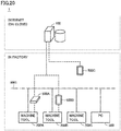
- FIG. 1 is a diagram showing an example of a system configuration of information processing system 1.
- Information processing system 1 includes an information processing device 100 and a plurality of machine tools 200A to 200D.
- Machine tools 200A to 200D are disposed, for example, in a factory.
- Machine tools 200A to 200D may be identical or different in type.
- at least one of machine tools 200A to 200D will also be referred to as a machine tool 200.
- a type of machine tool 200 is for example a lathe or a machining center.
- a lathe processes a workpiece by applying a tool to the workpiece while turning the workpiece by a spindle.
- a machining center processes a workpiece by applying a tool to the workpiece while turning the tool by a spindle.
- Information processing device 100 is a server installed at a location different from the factory where machine tools 200A to 200D are installed. Information processing device 100 collects various pieces of information about machine tools 200A to 200D from the machine tools and makes a database of the information. As an example, information processing device 100 collects a spindle's acceleration as sensed by an acceleration sensor, a machine tool's internal temperature as sensed by a temperature sensor, information about a hydraulic unit in the machine tool, a result of monitoring an oil cooler, and the like. These pieces of information are collected by a function, which may be a physical server, and may for example be provided in a platform on the cloud.
- Machine tool 200 is connected to network NW in any manner.
- machine tools 200A and 200B are connected to network NW via a router 401.
- Machine tool 200C is connected to network NW via an IO (input/output) unit and router 401.
- Machine tool 200D is directly connected to network NW
- information processing system 1 may include PCs (personal computers) 300A and 300B.
- PC 300A is indirectly networked to information processing device 100 via router 401.
- PC 300B is directly networked to information processing device 100.
- FIG. 2 is a sequence diagram showing a flow of data between information processing device 100 and machine tools 200A, 200B.
- Each machine tool 200 includes a sensor to sense information about the machine tool per se.
- information processing device 100 collects from each of machine tools 200 part information about a part of machine tool 200 to be maintained, and sensed information obtained by a sensor internal to machine tool 200. Subsequently, based on the information collected from each of machine tools 200, information processing device 100 learns, through machine-learning (or data-mining), a correlation between the part information of machine tool 200 and the sensed information obtained by the sensor internal to machine tool 200. Information processing device 100 refers to the correlation obtained as a learning result to predict a lifetime for the part to be maintained, determines whether the part to be maintained has a defect, and the like.
- step S10 information processing device 100 periodically receives from machine tool 200A sensed information obtained by the sensor internal to machine tool 200A.
- the sensed information received has imparted thereto a time at which the information is sensed, and information processing device 100 receives the sensed information as a history of sensing.
- information processing device 100 periodically receives from machine tool 200B sensed information obtained by a sensor internal to machine tool 200B.
- the sensed information received has imparted thereto a time at which the information is sensed, and information processing device 100 receives the sensed information as a history of sensing.
- the histories of sensing received from machine tools 200A and 200B are stored in a database 124, which will be described later.
- step S20A it is assumed that a part of machine tool 200A to be maintained is replaced.
- the part to be maintained includes expendables such as a spindle, for example.
- machine tool 200A Based on the part to be maintained having been replaced with another, machine tool 200A transmits to information processing device 100 as part information a part ID (identification) for identifying the part to be maintained that is a target for replacement and the timing of replacing the part to be maintained.
- Information processing device 100 associates the part information received from machine tool 200A with the sensed information of machine tool 200A as received in step S10 before the timing of replacing the part to be maintained, and then stores these pieces of information in database 124 shown in Fig. 3 .
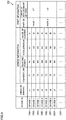
- Fig. 3 is a diagram showing an example of a data structure of database 124.
- a machine tool's device ID, a history of sensing (that is, the sensed information and the timing of sensing the information) received in step S10, and item information received in step S20A are associated with one another.
- the sensed information to be collected for example includes: temperature inside machine tool 200A as sensed by a temperature sensor; power consumption in machine tool 200A; acceleration of the spindle of machine tool 200A as sensed by an acceleration sensor; a value of a current flowing through a part to be maintained in machine tool 200A, as sensed by a current sensor; and the like.
- the item information to be collected includes, for example, a part ID for identifying a part to be maintained that is a target for replacement, and a timing of replacing the part to be maintained.
- step S20B it is assumed that a part of machine tool 200B to be maintained is replaced.
- Machine tool 200B transmits to information processing device 100 as part information a part ID for identifying the part to be maintained that is a target for replacement and the timing of replacing the part to be maintained.
- Information processing device 100 associates the part information received from machine tool 200B with the sensed information of machine tool 200B as received in step S10 before the timing of replacing the part to be maintained, and then stores these pieces of information in database 124 shown in Fig. 3 .
- information processing device 100 receives as collected data from each of machine tools 200 item information about a part to be maintained that is a target for replacement and sensed information obtained by a sensor before the timing of replacing the part to be maintained.
- Information processing device 100 stores in database 124 the collected data received from each of machine tools 200.
- collected data 125A to 125H is accumulated in database 124.
- step S30 information processing device 100 receives a learning instruction for the sake of illustration.
- the learning instruction may be issued based on a user operation done to information processing device 100 or may be issued as a preset timing of learning has arrived.
- step S32 information processing device 100 executes a learning process for machine-learning a correlation between the collected data accumulated in database 124.
- information processing device 100 learns, based on database 124, through machine-learning, a correlation between a timing of replacing a part of machine tool 200 to be maintained and sensed information obtained by a sensor internal to machine tool 200.
- information processing device 100 calculates for each of collected data 125A to 125H a period of time from a timing of sensing sensed information to a timing of replacing a part to be maintained (hereinafter also referred to as a "lifetime"). Thereafter, information processing device 100 learns, through machine-learning, a correlation between each sensed information indicated in database 124 and a lifetime calculated for each sensed information, by type of part to be maintained.
- Various learning methods such as a neural network and a support vector machine can be adopted for machine-learning the correlation.
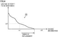
- Fig. 4 is a diagram showing an example of a correlation 126 obtained as a learning result.
- correlation 126 obtained as a learning result for a part" 1" to be maintained in machine tool 200 is shown.
- the horizontal axis for correlation 126 represents sensed information obtained by a sensor internal to machine tool 200.
- the sensed information is represented in one dimension for convenience of explanation, the sensed information may be represented by a number of dimensions corresponding to the type of the sensed information.
- the vertical axis for correlation 126 represents the lifetime of part " 1 " to be maintained.
- step S40 machine tool 200A receives an instruction from a user to estimate the lifetime of part "1" to be maintained for the sake of illustration.
- machine tool 200A outputs a sensing instruction to its internal sensor and obtains new sensed information from the sensor.
- step S42 machine tool 200A transmits the new sensed information to information processing device 100.
- step S44 in response to having received the new sensed information obtained by the sensor of machine tool 200A, information processing device 100 refers to correlation 126 learned in step S32 and thus determines a lifetime corresponding to the received new sensed information as a result of estimating the lifetime of part "1" to be maintained. For example, when information processing device 100 receives sensed information "ml" from machine tool 200A, information processing device 100 estimates a lifetime " ⁇ T" corresponding to the sensed information "ml” as the lifetime of part" 1" to be maintained.
- the estimated lifetime is output in any manner. As an example, the estimated lifetime may be output as a message on a screen or may be output audibly. For example, a message such as "Lifetime will expire in about 10 hours" is displayed.
- information processing device 100 receives sensed information "m2" from machine tool 200A, information processing device 100 estimates a lifetime of "0" corresponding to the sensed information "m2" as the lifetime of part" 1" to be maintained. That is, in that case, it is determined that the lifetime of part "1" to be maintained has expired.
- step S46 information processing device 100 transmits to machine tool 200A the lifetime estimation result obtained in step S44.
- Machine tool 200A receives the lifetime estimation result from information processing device 100 and outputs the same.
- the lifetime estimation result is output in any manner.
- the lifetime estimation result may be output on a screen or audibly or may cause an order to be automatically issued to a manufacturer for a spare part or a request to be issued for maintenance.
- a timing of replacing a part to be maintained is collected as part information of machine tool 200
- other part information may be collected.
- a timing of a failure of a part of machine tool 200 to be maintained may be collected.
- information processing device 100 collects from each machine tool 200 part information including a timing of a failure of a part of machine tool 200 to be maintained and sensed information obtained by a sensor before the timing of the failure of the part to be maintained. Subsequently, based on the collected data, information processing device 100 learns, through machine-learning, a correlation between the timing of the failure of the part of the machine tool to be maintained and the sensed information obtained by the sensor internal to that machine tool.
- information processing device 100 refers to the correlation obtained as a learning result to specify a timing of a failure of the part to be maintained that corresponds to the received new sensed information. Based on the specified timing of the failure, information processing device 100 determines a timing of replacing the part to be maintained.
- an impurity level (or contamination) of a coolant of machine tool 200 may be sensed.
- information processing device 100 collects from each of machine tools 200 part information including a level of impurity of the coolant and sensed information obtained by the sensor (for example, temperature, the coolant's hydraulic pressure, and the like). Subsequently, based on the collected data, information processing device 100 learns, through machine-learning, a correlation between the coolant's impurity level and the sensed information obtained by the sensor. Thereafter, when new sensed information is received from machine tool 200, information processing device 100 refers to the correlation obtained as a learning result to sense the coolant's impurity level corresponding to the received new sensed information.
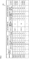
- Fig. 5 is a diagram showing an example of a database 124A according to a modified example.
- database 124 shown in Fig. 3 sensed information obtained by the sensor internal to machine tool 200 and part information about a part to be maintained have been collected.
- operation information indicating an operation status of machine tool 200 is further collected.
- information processing device 100 collects sensed information obtained by machine tool 200, part information of machine tool 200, and operation information of machine tool 200 from each of machine tools 200.
- the operation information for example includes a traveling distance, the spindle's operation time, a power supply's state (ON or OFF), an issued alarm, and the like.
- information processing device 100 When performing the learning process, information processing device 100 refers to database 124A to learn a correlation between the sensed information obtained by machine tool 200, the part information of machine tool 200, and the operation information of machine tool 200 through machine-learning for each type of part to be maintained.
- Other operation information may be collected. For example, information of a failure of a cylinder of an automatic door of machine tool 200, how many times the automatic door is opened/closed, when the automatic door is opened/closed, alarm information related to the automatic door, model type, and the like may be collected as the other operation information. In that case, from information of replacing the cylinder of the automatic door, the operation information, and the model type information, information processing device 100 can estimate an alarm before the door cylinder fails.
- FIG. 6 is a diagram showing an example of a functional configuration of information processing device 100.
- information processing device 100 includes a control device 101 and a storage device 120 (a storage unit) as a hardware configuration.
- Control device 101 includes a communication unit 152, a learning unit 154, a lifetime estimation unit 156, and a failure determination unit 158 as a functional configuration.
- Communication unit 152 receives as collected data from each of machine tools 200 part information about a part of machine tool 200 to be maintained and sensed information obtained by a sensor internal to machine tool 200.
- the collected data received is successively stored in database 124 (see Fig. 3 ) stored in storage device 120.
- learning unit 154 learns, through machine-learning, correlation 126 (see Fig. 4 ) between the part information of machine tool 200 and the sensed information obtained by the sensor internal to machine tool 200.
- a timing of replacing a part of machine tool 200 to be maintained and sensed information obtained by a sensor internal to machine tool 200 are collected in database 124.
- Learning unit 154 refers to database 124 to learn, through machine-learning, a correlation between the timing of replacing the part of machine tool 200 to be maintained and the sensed information obtained by the sensor internal to machine tool 200.
- a timing of a failure of a part of machine tool 200 to be maintained and sensed information obtained by a sensor internal to machine tool 200 are collected in database 124.
- Learning unit 154 refers to database 124 to learn, through machine-learning, a correlation between the timing of the failure of the part of machine tool 200 to be maintained and the sensed information obtained by the sensor internal to machine tool 200.
- lifetime estimation unit 156 refers to correlation 126 to specify for each part of machine tool 200 to be maintained a timing of replacement corresponding to the sensed information received. Based on the specified timing of replacement, lifetime estimation unit 156 estimates a lifetime of each part to be maintained.
- failure determination unit 158 When new sensed information is received from machine tool 200, failure determination unit 158 refers to correlation 126 to specify for each part of machine tool 200 to be maintained a timing of replacement corresponding to the sensed information received. Based on the specified timing of replacement, failure determination unit 158 determines failure of each part to be maintained.
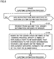
- FIG. 7 is a flowchart representing a learning process performed by information processing device 100.
- Fig. 8 is a flowchart representing a process performed by information processing device 100 for estimating a lifetime of a part to be maintained.
- the processes in Figs. 7 and 8 are implemented by information processing device 100's control device 101 executing a program. In another aspect, the processes may partially or entirely be performed by a circuit element or other hardware.
- control device 101 initially performs the learning process shown in Fig. 7 , and thereafter performs the lifetime estimation process shown in Fig. 8 .
- learning process shown in Fig. 7 and the lifetime estimation process shown in Fig. 8 will be described in order.
- control device 101 determines whether sensed information obtained by the sensor of machine tool 200 has been received from machine tool 200.
- control device 101 determines that the sensed information obtained by the sensor of machine tool 200 has been received from machine tool 200 (YES in step S I 10)
- control device 101 proceeds to step S112. Otherwise (NO in step S110), control device 101 proceeds to step S120.
- control device 101 writes to database 124 (see Fig. 3 ) the sensed information received from machine tool 200 in step S110.
- Sensed information to be collected for example includes: temperature inside machine tool 200 as sensed by a temperature sensor; power consumption in machine tool 200A; acceleration of the spindle of machine tool 200A as sensed by an acceleration sensor; a value of a current flowing through a part to be maintained in machine tool 200A, as sensed by a current sensor; and the like.
- step S120 control device 101 determines whether part information about a part to be maintained has been received from machine tool 200.
- control device 101 determines that part information about a part to be maintained has been received from machine tool 200 (YES in step S120)
- control device 101 proceeds to step S122. Otherwise (NO in step S120), control device 101 proceeds to step S130.
- control device 101 writes to database 124 (see Fig. 3 ) the part information received from machine tool 200 in step S110.
- Part information to be collected includes, for example, a timing of replacing a part to be maintained, a part ID for identifying the part to be maintained, and the like.
- control device 101 determines whether an instruction has been received to perform the learning process.
- the instruction may be issued based on a user operation done to information processing device 100 or machine tool 200 or may be issued as a preset timing of learning has arrived.
- control device 101 determines that an instruction to perform the learning process has been received from the user (YES in step S130)
- control device 101 proceeds to step S132. Otherwise (NO in step S130), control device 101 returns to step S110.
- control device 101 learns, through machine-learning, a correlation between the sensed information and part information accumulated in database 124.
- correlation 126 described above is obtained.
- step S150 control device 101 determines whether an instruction has been received to perform the lifetime estimation process.
- the instruction may be issued based on a user operation done to information processing device 100 or machine tool 200 or may be issued as a preset timing of learning has arrived.
- control device 101 determines that an instruction to perform the lifetime estimation process has been received (YES in step S150)
- control device 101 proceeds to step S152. Otherwise (NO in step S150), control device 101 performs step S150 again.
- control device 101 transmits a sensing instruction to machine tool 200 that is a target for estimation of lifetime.
- machine tool 200 obtains sensed information obtained by the sensor internal to machine tool 200.
- Machine tool 200 transmits the obtained sensed information to information processing device 100.
- control device 101 specifies, based on the correlation obtained in the learning process shown in Fig. 7 , a timing of replacing a part to be maintained, that corresponds to the sensed information received in step S152. Based on the timing of replacement specified, control device 101 estimates the lifetime of the part to be maintained.
- the lifetime estimation process is as has been described with reference to Fig. 4 , and accordingly, will not be described repeatedly.
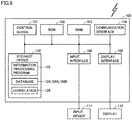
- Fig. 9 is a block diagram showing a main hardware configuration of information processing device 100.
- Information processing device 100 includes a control device 101, a ROM (Read Only Memory) 102, a RAM (Random Access Memory) 103, a communication interface 104, a display interface 105, an input interface 106, and storage device 120.
- ROM Read Only Memory
- RAM Random Access Memory
- Control device 101 controls information processing device 100.
- Control device 101 is composed for example of at least one integrated circuit.
- the integrated circuit is configured for example by at least one CPU (central processing unit), at least one ASIC (application specific integrated circuit), at least one FPGA (field programmable gate array) or a combination thereof, or the like.
- Control device 101 controls an operation of information processing device 100 by executing various programs such as an information processing program 122 according to the present embodiment.
- Control device 101 reads information processing program 122 from storage device 120 into ROM 102 in response to an instruction received to execute information processing program 122.
- RAM 103 functions as a working memory and temporarily stores various data necessary for executing information processing program 122.
- Information processing device 100 communicates data with an external communication device via communication interface 104.
- the external communication device includes, for example, machine tool 200, a server, other communication terminals, and the like.
- Information processing device 100 may be configured to be capable of downloading information processing program 122 from the server.
- Display interface 105 is connected to a display 110 and sends an image signal to display 110 in accordance with a command issued from control device 101 or the like for displaying an image.
- Display 110 is, for example, a liquid crystal display, an organic EL display, or other display devices.
- Display 110 for example displays a result of estimating a lifetime of a part of machine tool 200 to be maintained, a result of determining whether the part to be maintained has failure, and the like.
- Input interface 106 is, for example, a USB (universal serial bus) terminal and is connected to an input device 111. Input interface 106 receives a signal indicating a user operation from input device 111. Input device 111 is, for example, a mouse, a keyboard, a touch panel, or any other device that can receive the user's operations. For a blade server constituting the cloud, it is unnecessary to include input interface 106 and display interface 105.
- USB universal serial bus
- Storage device 120 is, for example, a storage medium such as a hard disk or a flash memory.
- Storage device 120 stores information processing program 122 according to the present embodiment, database 124 (see Fig. 3 ), correlation 126 (see Fig. 4 ), and the like. Where information processing program 122, database 124, and correlation 126 are stored is not limited to storage device 120, and may be stored in a storage area (for example, cache memory or the like) of control device 101, ROM 102, RAM 103, an external device (e.g., machine tool 200), or the like.
- information processing program 122 may not be a single program and may instead be incorporated in a part of any program and thus provided. In that case, a process according to the present embodiment is implemented in cooperation with that program. Even such a program that does not include some module does not depart from the gist of information processing program 122 according to the present embodiment. Furthermore, a function provided by information processing program 122 may partially or entirely be implemented by dedicated hardware. Further, information processing device 100 and machine tool 200 may cooperate to execute information processing program 122.
- Fig. 10 is a block diagram showing a main hardware configuration of machine tool 200.
- Machine tool 200 includes a control device 201, a ROM 202, a RAM 203, a communication interface 204, a display interface 205, a temperature sensor 206, an acceleration sensor 207, a current sensor 208, an input interface 209, and a storage device 220.
- Control device 201 controls machine tool 200.
- Control device 201 is constituted by, for example, at least one integrated circuit.
- the integrated circuit is constituted by, for example, at least one CPU, at least one ASIC, at least one FPGA, a combination thereof, or the like.
- Control device 201 controls an operation of machine tool 200 by executing various programs such as a control program 222 for machine tool 200.
- Control device 201 reads control program 222 from storage device 220 into ROM 202 in response to an instruction received to execute control program 222.
- RAM 203 functions as a working memory and temporarily stores various data necessary for executing control program 222.
- Machine tool 200 communicates data with an external communication device via communication interface 204.
- the external communication device includes, for example, information processing device 100, other communication terminals, and the like.
- Machine tool 200 may be configured to be capable of downloading control program 222 from the communication terminal.
- Display interface 205 is connected to a display 210 and sends an image signal to display 210 in accordance with a command issued from control device 201 or the like for displaying an image.
- Display 210 is, for example, a liquid crystal display, an organic EL display, or other display devices.
- Temperature sensor 206 is provided in machine tool 200 and senses the temperature of a part to be maintained. Temperature sensor 206 periodically senses the temperature of the part to be maintained and transmits the sensed temperature to information processing device 100 via communication interface 204 as sensed information.
- Acceleration sensor 207 is provided in machine tool 200 and senses acceleration (or vibration) of a part to be maintained. As an example, acceleration sensor 207 senses acceleration of the spindle of machine tool 200. The sensed acceleration is transmitted as sensed information to information processing device 100 via communication interface 204.
- Current sensor 208 is provided in machine tool 200 and senses the value of a current flowing through a part to be maintained. Current sensor 208 periodically senses the value of the current flowing through the part to be maintained and transmits the sensed current's value as sensed information to information processing device 100 via communication interface 204.
- Input interface 209 is, for example, a USB terminal and is connected to an input device 211. Input interface 209 receives a signal indicating a user operation from input device 211. Input device 211 is, for example, a mouse, a keyboard, a touch panel, or any other device that can receive user operations.
- Storage device 220 is, for example, a storage medium such as a hard disk or a flash memory.
- Storage device 220 stores control program 222 and the like according to the present embodiment. Where control program 222 is stored is not limited to storage device 220, and may be stored in a storage area (for example, cache memory or the like) of control device 201, ROM 202, RAM 203, an external device (e.g., information processing device 100), or the like.
- Information processing device 100 collects sensed information obtained by a sensor internal to machine tool 200 and part information about a part to be maintained in machine tool 200.
- information processing device 100 according to a second embodiment collects an alarm issued in machine tool 200 and a method for handling the alarm. Subsequently, information processing device 100 learns, through machine-learning, by type of alarm, a correlation between the alarm issued in machine tool 200 and the method for handling the alarm.
- the remainder of information processing device 100 according to the second embodiment is the same as that of information processing device 100 according to the first embodiment, and accordingly, will not be described repeatedly.
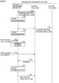
- FIG. 11 is a sequence diagram showing a flow of data between information processing device 100 and machine tools 200A, 200B according to the second embodiment.
- step S50 it is assumed that an alarm to be sensed is issued in machine tool 200A.
- Service personnel or a user operates machine tool 200A to handle the alarm issued for machine tool 200A.
- the service personnel or user inputs to a screen of machine tool 200A content of a failure of machine tool 200A and a method for handling the failure.
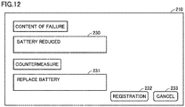
- Fig. 12 is a diagram showing an example of a screen displayed on display 210 of machine tool 200A.
- the screen shown in Fig. 12 is provided from an operating system referred to as "CELOS," for example.
- the screen includes, for example, an input area 230 for inputting content of a failure, an input area 231 for inputting a method for handling the failure, a registration button 232, and a cancel button 233.
- registration button 232 is pressed, the issued alarm's ID and information input to input areas 230 and 231 are transmitted to information processing device 100.
- cancel button 233 is pressed, the screen shown in Fig. 12 is closed.
- step S52 information processing device 100 associates the alarm ID received from machine tool 200A with the method for handling the alarm, and then stores these pieces of information in a database 124B shown in Fig. 13.
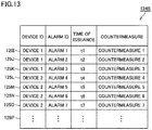
- Fig. 13 is a diagram showing an example of a data structure of database 124B.
- a machine tool's device ID, an alarm ID for identifying an alarm issued in the machine tool, the time at which the alarm is issued, and a method for handling the alarm are associated with one another by type of alarm.
- step S54 it is assumed that an alarm to be sensed is issued in machine tool 200B.
- Service personnel or a user operates machine tool 200B to handle the alarm issued in machine tool 200B.
- the service personnel or user inputs to a screen of machine tool 200B content of a failure of machine tool 200B and a method for handling the failure.
- Machine tool 200B transmits to information processing device 100 an alarm ID for identifying the alarm issued, the time at which the alarm is issued, and the method for handling the alarm.
- step S56 information processing device 100 associates the alarm ID received from machine tool 200B with the method for handling the alarm, and then stores these pieces of information in database 124B by type of alarm.
- step S60 information processing device 100 receives a learning instruction from the user for the sake of illustration.
- the learning instruction may be issued based on a user operation done to information processing device 100 or may be issued as a preset timing of learning has arrived.
- step S62 based on collected data 1251 to 125P of database 124B, information processing device 100 learns, through machine-learning, a correlation between the alarm and the method for handling the alarm, by type of alarm.
- Various learning methods such as a neural network and a support vector machine can be adopted for machine-learning the correlation.
- step S70 it is assumed that an alarm is further issued in machine tool 200A and the user performs a troubleshooting call operation for handling the alarm.
- step S72 machine tool 200A transmits an alarm ID to information processing device 100 for identifying the issued alarm.
- step S74 in response to the alarm ID received from machine tool 200A, information processing device 100 refers to the correlation learned in step S62 and thus obtains a method for handling the received alarm ID as troubleshooting.
- step S76 information processing device 100 transmits the method obtained in step S74 to machine tool 200A.
- Machine tool 200A outputs the method received from information processing device 100 as troubleshooting.
- the troubleshooting may be output on a screen or may be audibly output.
- information processing device 100 refers to the correlation learned in step S62 to determine a method for responding to the received alarm and output the determined method.
- information processing device 100 may collect: tool information (for example, manufacturer, tool type, and the like); type of workpiece; cutting conditions (for example, the spindle's rotational speed, cutting width, cutting depth, feed, and the like); a variety of types of sensor information including acceleration (for example, frequency, peak oscillation, and the like) as main information; the machine tool's state (for example, a coordinate along each axis, axial load, and the like); and the like.
- tool information for example, manufacturer, tool type, and the like
- type of workpiece for example, cutting conditions (for example, the spindle's rotational speed, cutting width, cutting depth, feed, and the like); a variety of types of sensor information including acceleration (for example, frequency, peak oscillation, and the like) as main information; the machine tool's state (for example, a coordinate along each axis, axial load, and the like); and the like.
- Information processing device 100 collects sensed information obtained by a sensor internal to machine tool 200 and part information about a part of machine tool 200 to be maintained.
- information processing device 100 according to a third embodiment collects sensed information obtained by the sensor internal to machine tool 200 and information about a tool used in a machining process performed by machine tool 200.
- the remainder of information processing device 100 according to the third embodiment is the same as that of information processing device 100 according to the first embodiment, and accordingly, will not be described repeatedly.
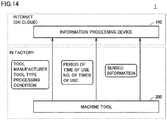
- FIG. 14 is a diagram showing an example of a system configuration of information processing system 1 according to the third embodiment.
- Information processing system 1 is composed of information processing device 100 and a plurality of machine tools 200s.
- a tool for processing a workpiece can be attached to the spindle of machine tool 200.
- the tool attached on the spindle can be automatically changed in accordance with the type of the workpiece and the processing mode of interest.
- Information processing device 100 collects from various machine tools 200 tool information about a tool used in the process for processing a workpiece.
- information processing device 100 collects a tool manufacturer, a tool type (for example, a tool ID), a work processing condition, and the like from machine tool 200 as the tool information.
- information processing device 100 collects information of how long a tool is used, how many times the tool is used, and the like from machine tool 200 as the tool information.
- information processing device 100 collects from machine tool 200 sensed information obtained by the sensor of machine tool 200 during the process for processing the workpiece. Information processing device 100 associates the tool information with the sensed information and thus stores the pieces of information in database 124.
- information processing device 100 learns, through machine-learning, a correlation between the tool information and the sensed information.
- the correlation is machine-learned by type of machine tool 200 and type of tool.
- Information processing device 100 can thus distinguish a tool's lifetime, damage, etc. by type of tool.
- Information processing device 100 collects sensed information obtained by a sensor internal to machine tool 200 and part information about a part of machine tool 200 to be maintained.
- information processing device 100 according to a fourth embodiment collects sensed information obtained by the sensor internal to machine tool 200 and a control parameter set for machine tool 200.
- the remainder of information processing device 100 according to the fourth embodiment is the same as that of information processing device 100 according to the first embodiment, and accordingly, will not be described repeatedly.
- FIG. 15 is a diagram showing an example of a system configuration of information processing system 1 according to the fourth embodiment.
- Information processing system 1 is composed of information processing device 100 and a plurality of machine tools 200s.
- Machine tool 200 is, for example, the MVX5000 series manufactured by DMG MORI CO., LTD.
- Machine tool 200 according to the present embodiment has a recommending function for recommending a candidate control parameter to be set for machine tool 200 per se.
- a recommending function by an MVC (machine vibration control) manufactured by DMG MORI CO., LTD is adopted.
- the MVC machine vibration control
- the MVC automatically presents a recommended condition to a user for reducing the chatter.
- machine tool 200 sets a control parameter corresponding to the selected recommended condition. As a result, the control parameter is optimized and the chatter is alleviated.
- Information processing device 100 collects from various machine tools 200 a recommended condition selected from those recommended by the MVC. More specifically, machine tool 200 includes CELOS 240 serving as an operating system, and CELOS 240 obtains from MVC 242 a condition 245 recommended by MVC 242 and an operation result 246 obtained as recommended condition 245 is adopted. Operation result 246 indicates whether chatter was reduced by adopting recommended condition 245, and it is expressed by, for example, by what percentage the chatter has successfully been reduced.
- acceleration sensor 207 obtains acceleration of the spindle of machine tool 200 as vibration data.
- An FFT (Fast Fourier Transform) unit 241 subjects to fast Fourier transform the vibration data obtained from acceleration sensor 207. As a result, the vibration data is subjected to frequency division. A result of the Fourier transform is output to CELOS 240.
- CELOS 240 transmits sensed information obtained by acceleration sensor 207, recommended condition 245, and operation result 246 to information processing device 100.
- Information processing device 100 collects these pieces of information as collected data from various machine tools 200, associates the sensed information, recommended condition 245 and operation result 246 with one another, and thus stores these pieces of information in database 124.
- information processing device 100 learns, through machine-learning, by type of operation result 246, a correlation among the accumulated sensed information, recommended condition 245, and operation result 246.
- Information processing device 100 can thus more precisely estimate a cutting condition or the like for reducing chatter, and thus allows more efficient cutting.
- information processing device 100 receives as collected data from machine tool 200 sensed information obtained by acceleration sensor 207, recommended condition 245 selected from recommended candidates, and operation result 246 indicating whether chatter is reduced by setting for machine tool 200 a control parameter corresponding to recommended condition 245.
- Information processing device 100 accumulates in database 124 the collected data received from machine tool 200. Subsequently, based on the collected data accumulated in database 124, information processing device 100 learns, through machine-learning, a correlation among the sensed information obtained by acceleration sensor 207, recommended condition 245, and operation result 246.
- information processing device 100 may collect: tool information (for example, manufacturer, tool type, and the like); type of workpiece; cutting conditions (for example, the spindle's rotational speed, cutting width, cutting depth, feed, and the like); a variety of types of sensor information including acceleration (for example, frequency, peak oscillation, and the like) as main information; the machine tool's state (for example, a coordinate along each axis, axial load, and the like); and the like in the course of processing by using MVC 242.
- tool information for example, manufacturer, tool type, and the like
- type of workpiece for example, cutting conditions (for example, the spindle's rotational speed, cutting width, cutting depth, feed, and the like); a variety of types of sensor information including acceleration (for example, frequency, peak oscillation, and the like) as main information; the machine tool's state (for example, a coordinate along each axis, axial load, and the like); and the like in the course of processing by using MVC 242.
- cutting conditions for example, the
- Information processing device 100 collects sensed information obtained by a sensor internal to machine tool 200 and part information about a part of machine tool 200 to be maintained.
- information processing device 100 according to a fifth embodiment collects sensed information obtained by the sensor internal to machine tool 200 and correction information of a control parameter set for machine tool 200.
- the remainder of information processing device 100 according to the fifth embodiment is the same as that of information processing device 100 according to the first embodiment, and accordingly, will not be described repeatedly.
- FIG. 16 is a diagram showing an example of a system configuration of information processing system 1 according to the fifth embodiment.
- Information processing system 1 is composed of information processing device 100 and a plurality of machine tools 200s.
- Machine tool 200 is, for example, the DMU series, the NTX series, or the like manufactured by DMG MORI CO., LTD.
- Machine tool 200 according to the present embodiment includes an interface 248 for connecting a correction device 250 for correcting a control parameter for machine tool 200.
- correction device 250 is "3D Quick Set.”
- “3D Quick Set” is a tool kit which measures a geometric intersection of a pivot axis using a touch probe and a true sphere and uses the measurement result to automatically correct an error of the spindle of machine tool 200, an error of the turning center of the table, and the like.
- Information processing device 100 collects from various machine tools 200 correction information of a control parameter corrected by correction device 250. More specifically, machine tool 200 includes CELOS 240 serving as an operating system, and CELOS 240 obtains from correction device 250 via interface 248 the correction information of the control parameter corrected by correction device 250. CELOS 240 transmits to information processing device 100 the correction information obtained from correction device 250.
- temperature sensor 206 senses maintenance temperature of a component in machine tool 200.
- temperature sensor 206 is provided for each component of a temperature sensing target.
- Temperature sensor 206 senses, for example, the temperature of the spindle, the temperature of a table for holding the workpiece, the temperature of a bed, the temperature of a tank, and the like. The temperature sensed by temperature sensor 206 is transmitted to information processing device 100 as sensed information 243.
- Information processing device 100 collects sensed information 243 from temperature sensor 206 and the correction information from correction device 250 as collected data from various machine tools 200, associates the former information with the latter information, and thus accumulates these pieces of information in database 124. Subsequently, information processing device 100 learns, through machine-learning, a correlation between the sensed information and the correction information that are accumulated. Preferably, the correlation is machine-learned by type of machine tool 200 and type of part to be maintained. This allows information processing device 100 to build an algorithm that can estimate, before measurement, that an error is increasingly larger, based on the sensed information from the temperature sensor, and provide feedback to machine tool 200 accordingly. In addition, machine tool 200 can precisely predict deterioration in precision based on the sensed information from the temperature sensor, and can thus estimate a timing of using correction device 250.
- information processing device 100 receives as collected data from various machine tools 200 sensed information obtained by temperature sensor 206 and correction information of a control parameter corrected by correction device 250.
- Information processing device 100 accumulates in database 124 the collected data received from machine tool 200. Subsequently, based on the collected data accumulated in database 124, information processing device 100 learns, through machine-learning, a correlation between the sensed information obtained by temperature sensor 206 and the correction information provided by correction device 250.
- information processing device 100 may further collect operation information indicating an operation status of machine tool 200.
- information processing device 100 provides a function that allows the user himself/herself to periodically diagnose machine tool 200.
- the remainder of information processing device 100 according to the sixth embodiment is the same as that of information processing device 100 according to the first embodiment, and accordingly, will not be described repeatedly.
- Fig. 17 is a sequence diagram showing a flow of data between information processing device 100 and machine tools 200A, 200B according to the sixth embodiment.
- step S80 information processing device 100 periodically receives as collected data from machine tool 200A sensed information obtained by the sensor of machine tool 200A.
- the collected data received is stored in database 124 (see Fig. 3 ).
- information processing device 100 periodically receives as collected data from machine tool 200B sensed information obtained by the sensor internal to machine tool 200B.
- the collected data received is stored in database 124 (see Fig. 3 ).
- step S82 in response to a learning instruction received from the user, information processing device 100 performs a process for learning the collected data accumulated in database 124.
- information processing device 100 learns the sensed information's normal range by type of sensor.
- information processing device 100 calculates the sensed information's average value and standard deviation for each type of sensor, and learns as the normal range a range between a lower limit value obtained by subtracting a predetermined multiple of the standard deviation from the average value and an upper limit value obtained by adding the predetermined multiple of the standard deviation from the average value.
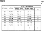
- Fig. 18 is a diagram showing an example of a learning result 126A as obtained through a learning process done by information processing device 100.
- learning result 126A a normal range for sensed information obtained by each sensor is defined by type of device and type of part.
- Learning result 126A is stored, for example, in storage device 120 of information processing device 100.
- step S84 it is assumed that machine tool 200A receives an instruction to perform a diagnostic process.
- the user prepares in advance a workpiece of a specific size and a specific material in machine tool 200A, and executes a self-diagnosis program.
- Machine tool 200A thus executes an NC program prepared for self-diagnosis, and starts processing the workpiece using a specific tool.
- step S86 while processing the workpiece, machine tool 200A monitors and collects the sensor's sensed information.
- the sensed information to be collected includes, for example, fluctuation of a load of a motor that drives the spindle, fluctuation in temperature of the spindle, fluctuation in temperature of coolant, the spindle's vibration, fluctuation of a load of the motor related to a locus of a tool such as the XYAB axes, encoder locus data related to the locus of the tool such as the XYAB axes, and the like.
- step S88 machine tool 200A transmits to information processing device 100 the sensed information collected in step S86.
- a shape of a specific portion of the workpiece may be measured by a measuring unit (for example, a touch probe or the like) provided in machine tool 200A, and in that case, the measurement result is further transmitted to machine tool 200A.
- a measuring unit for example, a touch probe or the like
- step S90 information processing device 100 diagnoses machine tool 200A based on the sensed information received from machine tool 200A. More specifically, information processing device 100 refers to learning result 126A obtained through the learning process performed in step S82 to determine whether each type of sensed information falls within the normal range, and diagnose machine tool 200A based on the determination. As an example, information processing device 100 compares machine tool 200A's state of vibration, machine tool 200A's temperature fluctuation range, machine tool 200A's quadrant glitch (backlash), machine tool 200A's operation load along each axis, etc. with normal ranges, respectively, specified in learning result 126A.
- step S92 information processing device 100 transmits to machine tool 200A a chart obtained as a diagnosis result obtained in step S90.
- step S94 machine tool 200A displays the diagnosis result received from information processing device 100.
- Fig. 19 is a diagram showing an example of a diagnosis result screen 260 displayed on display 210 of machine tool 200A.
- diagnosis result screen 260 shows a determination result indicating a normal level for each sensed information. Furthermore, for sensed information deviating from the normal range, a countermeasure (for example, adjustment, replacing a part, making a contact with a manufacturer, etc.) is indicated. Further, for sensed information within the normal range, a prediction of when a failure will occur is indicated from a degree of change as compared with past data.
- a countermeasure for example, adjustment, replacing a part, making a contact with a manufacturer, etc.
- information processing device 100 stores a chart obtained as a diagnosis result whenever the diagnostic process is performed.
- information processing device 100 can accumulate a large number of charts, and, by machine-learning them together with a maintenance record, estimate a probability of occurrence of failure in the future.
- information processing device 100 receives as collected data from various machine tools 200 sensed information obtained by each of a plurality of sensors in machine tool 200.
- Information processing device 100 accumulates in database 124 the collected data received from machine tool 200. Subsequently, based on the collected data accumulated in database 124, information processing device 100 learns a normal range for the sensed data by type of sensor. Thereafter, when information processing device 100 receives an instruction from any machine tool to diagnose the machine tool, information processing device 100 receives from the machine tool the sensed information obtained by the sensor internal to the machine tool, and refers to a learning result obtained through the above learning process to diagnose whether each of the sensed information received falls within a normal range corresponding thereto. Information processing device 100 transmits a diagnosis result to the machine tool that has issued the instruction to perform the diagnostic process.
- accumulated diagnosis results can be utilized for failure prediction.
- information processing device 100 and machine tool 200 belong to the same network. In contrast, in information processing system 1 according to a seventh embodiment, information processing device 100 and machine tool 200 do not belong to the same network.
- the remainder of information processing device 100 according to the seventh embodiment is the same as that of information processing device 100 according to the first embodiment, and accordingly, will not be described repeatedly.
- FIG. 20 is a diagram showing an example of the system configuration of information processing system 1 according to the seventh embodiment.
- Information processing system 1 includes, for example, information processing device 100, machine tools 200A to 200C, a PC 300, and communication terminals 500A to 500C.
- Machine tools 200A to 200C and PC 300 are connected to each other via a network NW1.
- Information processing device 100 and machine tools 200A to 200C are not networked directly. Separating information processing device 100 and the network of machine tools 200A to 200C ensures security.
- Communication terminal 500A is, for example, a communication adapter.
- MMLink registered trademark
- Communication terminals 500B and 500C are portable terminals such as a smart phone and a tablet.
- FIG. 21 is a diagram showing an example of collected data 125 collected from machine tool 200 by information processing device 100.
- information processing device 100 also collects from machine tool 200 various pieces of information indicated in collected data 125.
- an information processing method comprises the step of communicating with a plurality of machine tools.
- the plurality of machine tools each include a sensor to sense information about the machine tool as sensed information.
- the step of communicating includes the step of receiving as collected data from each of the plurality of machine tools part information about a part of the machine tool and the sensed information obtained by the sensor.
- the information processing method further comprises the steps of: storing in a storage unit the collected data received from each of the plurality of machine tools; and based on the plurality of collected data stored in the storage unit, learning a correlation between part information of a machine tool and sensed information obtained by the sensor internal to that machine tool.
- the step of communicating includes the step of receiving as the collected data from each of the plurality of machine tools the part information including a timing of replacing a part of the machine tool and sensed information obtained by the sensor that is obtained before the timing of replacing the part of the machine tool.
- the step of learning includes the step of learning a correlation between a timing of replacing a part of a machine tool and sensed information obtained by the sensor internal to that machine tool, based on the plurality of collected data stored in the storage unit.
- the information processing method further comprises a lifetime estimation portion such that when new sensed information obtained by the sensor is received from any of the plurality of machine tools and other machine tools, the lifetime estimation unit refers to the correlation to specify a timing of replacing a part, that corresponds to the new sensed information received, and estimate a lifetime for that part, based on the timing of replacing the part as specified.
- the step of communicating includes the step of receiving as the collected data from each of the plurality of machine tools the part information including a timing of a failure of a part of the machine tool and sensed information obtained by the sensor that is obtained before the timing of the failure of that part.
- the step of learning includes the step of learning a correlation between a timing of a failure of a part of a machine tool and sensed information obtained by the sensor internal to that machine tool, based on the plurality of collected data stored in the storage unit.
- the information processing method further comprises the steps of, when new sensed information obtained by the sensor is received from any of the plurality of machine tools and other machine tools, referring to the correlation to specify a timing of a failure of a part, that corresponds to the new sensed information received, and determine a timing of replacing that part, based on the timing of the failure as specified.
- an information processing method comprises the step of communicating with a plurality of machine tools.
- the step of communicating includes the step of receiving as collected data from each of the plurality of machine tools content of an alarm issued in the machine tool and a method performed for the machine tool to handle the alarm when the alarm is issued.
- the information processing method further comprises the steps of: storing in a storage unit the collected data received from each of the plurality of machine tools; and based on the plurality of collected data stored in the storage unit, learning for each type of the alarm a correlation between the alarm and the method performed to handle the alarm.
- the information processing method further comprises the step of, when a further alarm issued in any of the plurality of machine tools and other machine tools is received from that machine tool, referring to the correlation to determine a method for handling the further alarm received, and output the method as determined.
- an information processing method comprises the step of communicating with a plurality of machine tools.
- the plurality of machine tools each include a sensor to sense information about the machine tool as sensed information, and a recommending function for recommending a candidate for a recommended condition for a control parameter for reducing vibration of a spindle of the machine tool.
- the step of communicating includes the step of receiving as collected data from each of the plurality of machine tools the sensed information obtained by the sensor, a recommended condition selected from such candidates, and a result indicating whether the vibration is reduced by setting for the machine tool a control parameter corresponding to the recommended condition.
- the information processing method further comprises the steps of: storing in a storage unit the collected data received from each of the plurality of machine tools; and based on the plurality of collected data stored in the storage unit, learning a correlation among sensed information obtained by the sensor internal to a machine tool, a recommended condition selected from the candidates, and the result.
- an information processing method comprises the step of communicating with a plurality of machine tools.
- the plurality of machine tools each include a sensor to sense information about the machine tool as sensed information, and an interface for connecting to a correction device for correcting a control parameter for the machine tool.
- the step of communicating includes the step of receiving as collected data from each of the plurality of machine tools the sensed information obtained by the sensor and correction information of the control parameter corrected by the correction device.
- the information processing method further comprises the steps of: storing in a storage unit the collected data received from each of the plurality of machine tools; and based on the plurality of collected data stored in the storage unit, learning a correlation between sensed information obtained by the sensor internal to a machine tool and correction information provided by the correction device.
- an information processing method comprises the step of communicating with a plurality of machine tools.
- the plurality of machine tools each include a plurality of sensors to sense different types of information about the machine tool.
- the step of communicating includes the step of receiving as collected data from each of the plurality of machine tools sensed information obtained by each of the plurality of sensors internal to the machine tool.
- the information processing method further comprises the steps of: storing in a storage unit the collected data received from each of the plurality of machine tools; and based on the plurality of collected data stored in the storage unit, learning a normal range for sensed information for each of types of the plurality of sensors; when an instruction is received from any of the plurality of machine tools and other machine tools to conduct a diagnosis, receiving from that machine tool sensed information obtained by the plurality of sensors internal to the machine tool, and referring to a learning result obtained through the step of learning to make a diagnosis of whether each of the sensed information received falls within a normal range corresponding thereto; and transmitting the diagnosis to the machine tool that has issued the instruction.
- an information processing system comprises an information processing device, and a plurality of machine tools capable of communicating with the information processing device.
- the plurality of machine tools each include a sensor to sense information about the machine tool as sensed information.
- the information processing device includes: a communication unit configured to receive as collected data from each of the plurality of machine tools part information about a part of the machine tool and the sensed information obtained by the sensor; a storage unit configured to store the collected data received from each of the plurality of machine tools; and a learning unit configured to learn, based on the plurality of collected data stored in the storage unit, a correlation between part information of a machine tool and sensed information obtained by the sensor internal to that machine tool.
- an information processing device comprises a communication unit configured to communicate with a plurality of machine tools.
- the plurality of machine tools each include a sensor to sense information about the machine tool as sensed information.
- the communication unit receives as collected data from each of the plurality of machine tools part information about a part of the machine tool and the sensed information obtained by the sensor.
- the information processing device further comprises a storage unit configured to store the collected data received from each of the plurality of machine tools, and a learning unit configured to learn, based on the plurality of collected data stored in the storage unit, a correlation between part information of a machine tool and sensed information obtained by the sensor internal to that machine tool.
- 1 information processing system 100 information processing device, 101, 201 control device, 102, 202 ROM, 103, 203 RAM, 104, 204 communication interface, 105, 205 display interface, 106, 209 input interface, 110, 210 display, 111 input device, 120, 220 storage device, 122 information processing program, 124, 124A, 124B database, 125, 125A-125P collected data, 126 correlation, 126A learning result, 152 communication unit, 154 learning unit, 156 lifetime estimation unit, 158 failure determination unit, 200A-200D machine tool, 206 temperature sensor, 207 acceleration sensor, 208 current sensor, 222 control program, 230, 231 input area, 232 registration button, 233 cancel button, 241 FFT unit, 243 sensed information, 245 recommended condition, 246 operation result, 248 interface, 250 correction device, 260 diagnosis result screen, 300A, 300B, 500A-500C communication terminal, 401 router.
Landscapes
- Engineering & Computer Science (AREA)
- Physics & Mathematics (AREA)
- General Physics & Mathematics (AREA)
- Automation & Control Theory (AREA)
- Artificial Intelligence (AREA)
- Evolutionary Computation (AREA)
- Mechanical Engineering (AREA)
- Manufacturing & Machinery (AREA)
- Medical Informatics (AREA)
- Health & Medical Sciences (AREA)
- Software Systems (AREA)
- Computer Vision & Pattern Recognition (AREA)
- Human Computer Interaction (AREA)
- Evolutionary Biology (AREA)
- General Engineering & Computer Science (AREA)
- Quality & Reliability (AREA)
- Bioinformatics & Computational Biology (AREA)
- Bioinformatics & Cheminformatics (AREA)
- Life Sciences & Earth Sciences (AREA)
- Mathematical Physics (AREA)
- Numerical Control (AREA)
- General Factory Administration (AREA)
- Testing And Monitoring For Control Systems (AREA)
- Machine Tool Sensing Apparatuses (AREA)
- Management, Administration, Business Operations System, And Electronic Commerce (AREA)
Abstract
Description
- The present disclosure relates to a technique for collecting a variety of types of information from a plurality of machine tools.
- Various techniques relating to machine tools have been developed. For example, Japanese Patent No.
5992087 - As another example, International Publication No.
2002/003156 - As yet another example, International Publication No.
2000/012259 - As yet another example, Japanese Patent Application Laying-Open No.
2003-177815 -
- PTL 1: Japanese Patent No.
5992087 - PTL 2:
WO 2002/003156 - PTL 3:
WO 2000/012259 - PTL 4: Japanese Patent Laying-Open No.
2003-177815 - Technology capable of collecting information about various machine tools from the machine tools has been developed. However, as machine tools are diversified, collectable information is also enormous in type and amount, and it is now a problem that collected information is not effectively utilized. Therefore, a technique for effectively utilizing a variety of types of information collected from machine tools is desired.
-
Patent Literature 1 does not disclose what type of information is collected or how the information is utilized.Patent Literature 2 andPatent Literature 3 merely disclose collecting information based on actual processing data and do not disclose any other method for collecting or using information.Patent Literature 4 merely discloses collecting monitoring information of predetermined items of the industrial machine and does not disclose any other method for collecting or using information. - The present disclosure has been made to solve the above-described problems, and an object in an aspect is to provide an information processing method capable of effectively utilizing a variety of types of information collected from a machine tool. An object in another aspect is to provide an information processing system capable of effectively utilizing a variety of types of information collected from a machine tool. It is an object to provide an information processing device capable of effectively utilizing a variety of types of information collected from a machine tool.
- According to one aspect, an information processing method comprises the step of communicating with a plurality of machine tools. The plurality of machine tools each include a sensor to sense information about the machine tool as sensed information. The step of communicating includes the step of receiving as collected data from each of the plurality of machine tools part information about a part of the machine tool and the sensed information obtained by the sensor. The information processing method further comprises the steps of: storing in a storage unit the collected data received from each of the plurality of machine tools; and based on the plurality of collected data stored in the storage unit, learning a correlation between part information of a machine tool and sensed information obtained by the sensor internal to that machine tool.
- According to another aspect, an information processing method comprises the step of communicating with a plurality of machine tools. The step of communicating includes the step of receiving as collected data from each of the plurality of machine tools content of an alarm issued in the machine tool and a method performed for the machine tool to handle the alarm when the alarm is issued. The information processing method further comprises the steps of: storing in a storage unit the collected data received from each of the plurality of machine tools; and based on the plurality of collected data stored in the storage unit, learning for each type of the alarm a correlation between the alarm and the method performed to handle the alarm.
- According to another aspect, an information processing method comprises the step of communicating with a plurality of machine tools. The plurality of machine tools each include a sensor to sense information about the machine tool as sensed information, and a recommending function for recommending a candidate for a recommended condition for a control parameter for reducing vibration of a spindle of the machine tool. The step of communicating includes the step of receiving as collected data from each of the plurality of machine tools the sensed information obtained by the sensor, a recommended condition selected from such candidates, and a result indicating whether the vibration is reduced by setting for the machine tool a control parameter corresponding to the recommended condition. The information processing method further comprises the steps of: storing in a storage unit the collected data received from each of the plurality of machine tools; and based on the plurality of collected data stored in the storage unit, learning a correlation among sensed information obtained by the sensor internal to a machine tool, a recommended condition selected from the candidates, and the result.
- According to another aspect, an information processing method comprises the step of communicating with a plurality of machine tools. The plurality of machine tools each include a sensor to sense information about the machine tool as sensed information, and an interface for connecting to a correction device for correcting a control parameter for the machine tool. The step of communicating includes the step of receiving as collected data from each of the plurality of machine tools the sensed information obtained by the sensor and correction information of the control parameter corrected by the correction device. The information processing method further comprises the steps of: storing in a storage unit the collected data received from each of the plurality of machine tools; and based on the plurality of collected data stored in the storage unit, learning a correlation between sensed information obtained by the sensor internal to a machine tool and correction information provided by the correction device.
- According to another aspect, an information processing method comprises the step of communicating with a plurality of machine tools. The plurality of machine tools each include a plurality of sensors to sense different types of information about the machine tool. The step of communicating includes the step of receiving as collected data from each of the plurality of machine tools sensed information obtained by each of the plurality of sensors internal to the machine tool. The information processing method further comprises the steps of: storing in a storage unit the collected data received from each of the plurality of machine tools; based on the plurality of collected data stored in the storage unit, learning a normal range for sensed information for each of types of the plurality of sensors; when an instruction is received from any of the plurality of machine tools and other machine tools to conduct a diagnosis, receiving from that machine tool sensed information obtained by the plurality of sensors internal to the machine tool, and referring to a learning result obtained through the step of learning to make a diagnosis of whether each of the sensed information received falls within a normal range corresponding thereto; and transmitting the diagnosis to the machine tool that has issued the instruction.
- According to another aspect, an information processing system comprises an information processing device, and a plurality of machine tools capable of communicating with the information processing device. The plurality of machine tools each include a sensor to sense information about the machine tool as sensed information. The information processing device includes: a communication unit configured to receive as collected data from each of the plurality of machine tools part information about a part of the machine tool and the sensed information obtained by the sensor; a storage unit configured to store the collected data received from each of the plurality of machine tools; and a learning unit configured to learn, based on the plurality of collected data stored in the storage unit, a correlation between part information of a machine tool and sensed information obtained by the sensor internal to that machine tool.
- According to another aspect, an information processing device comprises a communication unit configured to communicate with a plurality of machine tools. The plurality of machine tools each include a sensor to sense information about the machine tool as sensed information. The communication unit receives as collected data from each of the plurality of machine tools part information about a part of the machine tool and the sensed information obtained by the sensor. The information processing device further comprises a storage unit configured to store the collected data received from each of the plurality of machine tools, and a learning unit configured to learn, based on the plurality of collected data stored in the storage unit, a correlation between part information of a machine tool and sensed information obtained by the sensor internal to that machine tool.
- In one aspect, a variety of types of information collected from a machine tool can be effectively utilized.
- The foregoing and other objects, features, aspects and advantages of the present invention will become more apparent from the following detailed description of the present invention when taken in conjunction with the accompanying drawings.
-
-
Fig. 1 is a diagram showing an example of a system configuration of an information processing system according to a first embodiment. -
Fig. 2 is a sequence diagram showing a flow of data between an information processing device and a machine tool according to the first embodiment. -
Fig. 3 is a diagram showing an example of a data structure of a database according to the first embodiment. -
Fig. 4 is a diagram showing an example of a correlation obtained as a learning result. -
Fig. 5 is a diagram showing an example of a database according to a modified example. -
Fig. 6 is a diagram showing an example of a functional configuration of the information processing device according to the first embodiment. -
Fig. 7 is a flowchart representing a learning process performed by the information processing device according to the first embodiment. -
Fig. 8 is a flowchart representing a process performed by the information processing device according to the first embodiment for estimating a lifetime of a part to be maintained. -
Fig. 9 is a block diagram showing a main hardware configuration of the information processing device according to the first embodiment. -
Fig. 10 is a block diagram showing a main hardware configuration of a machine tool according to the first embodiment. -
Fig. 11 is a sequence diagram showing a flow of data between the information processing device and a machine tool according to a second embodiment. -
Fig. 12 is a diagram showing an example of a screen displayed on a display of a machine tool according to the second embodiment. -
Fig. 13 is a diagram showing an example of a data structure of a database according to the second embodiment. -
Fig. 14 is a diagram showing an example of a system configuration of an information processing system according to a third embodiment. -
Fig. 15 is a diagram showing an example of a system configuration of an information processing system according to a fourth embodiment. -
Fig. 16 is a diagram showing an example of a system configuration of an information processing system according to a fifth embodiment. -
Fig. 17 is a sequence diagram showing a flow of data between the information processing device and a machine tool according to a sixth embodiment. -
Fig. 18 is a diagram showing an example of a learning result as obtained through a learning process done by the information processing device according to the sixth embodiment. -
Fig. 19 is a diagram showing an example of a diagnosis result screen displayed on a display of a machine tool according to a seventh embodiment. -
Fig. 20 is a diagram showing an example of a system configuration of an information processing system according to the seventh embodiment. -
Fig. 21 is a diagram showing an example of collected data collected from a machine tool by an information processing device according to an eighth embodiment. - Hereinafter, each embodiment according to the present invention will be described with reference to the drawings. In the following description, identical parts and components are identically denoted. Their names and functions are also identical. Accordingly, they will not be described repeatedly in detail. It should be noted that each embodiment and each modification described below may be selectively combined as appropriate.
- With reference to
Fig. 1 , aninformation processing system 1 for collecting information about a machine tool will be described.Fig. 1 is a diagram showing an example of a system configuration ofinformation processing system 1. -
Information processing system 1 includes aninformation processing device 100 and a plurality ofmachine tools 200A to 200D. -
Machine tools 200A to 200D are disposed, for example, in a factory.Machine tools 200A to 200D may be identical or different in type. Hereinafter, at least one ofmachine tools 200A to 200D will also be referred to as amachine tool 200. - A type of
machine tool 200 is for example a lathe or a machining center. A lathe processes a workpiece by applying a tool to the workpiece while turning the workpiece by a spindle. A machining center processes a workpiece by applying a tool to the workpiece while turning the tool by a spindle. -
Information processing device 100 is a server installed at a location different from the factory wheremachine tools 200A to 200D are installed.Information processing device 100 collects various pieces of information aboutmachine tools 200A to 200D from the machine tools and makes a database of the information. As an example,information processing device 100 collects a spindle's acceleration as sensed by an acceleration sensor, a machine tool's internal temperature as sensed by a temperature sensor, information about a hydraulic unit in the machine tool, a result of monitoring an oil cooler, and the like. These pieces of information are collected by a function, which may be a physical server, and may for example be provided in a platform on the cloud. -
Information processing device 100 andmachine tool 200 are connected to each other via a networkNW Machine tool 200 is connected to network NW in any manner. In the example ofFig. 1 ,machine tools router 401.Machine tool 200C is connected to network NW via an IO (input/output) unit androuter 401.Machine tool 200D is directly connected to network NW - In addition to
information processing device 100 andmachine tool 200,information processing system 1 may include PCs (personal computers) 300A and 300B.PC 300A is indirectly networked toinformation processing device 100 viarouter 401.PC 300B is directly networked toinformation processing device 100. - A learning process by
information processing device 100 will be described with reference toFigs. 2 to 4 .Fig. 2 is a sequence diagram showing a flow of data betweeninformation processing device 100 andmachine tools - Each
machine tool 200 includes a sensor to sense information about the machine tool per se. In the present embodiment,information processing device 100 collects from each ofmachine tools 200 part information about a part ofmachine tool 200 to be maintained, and sensed information obtained by a sensor internal tomachine tool 200. Subsequently, based on the information collected from each ofmachine tools 200,information processing device 100 learns, through machine-learning (or data-mining), a correlation between the part information ofmachine tool 200 and the sensed information obtained by the sensor internal tomachine tool 200.Information processing device 100 refers to the correlation obtained as a learning result to predict a lifetime for the part to be maintained, determines whether the part to be maintained has a defect, and the like. - More specifically, in step S10,
information processing device 100 periodically receives frommachine tool 200A sensed information obtained by the sensor internal tomachine tool 200A. The sensed information received has imparted thereto a time at which the information is sensed, andinformation processing device 100 receives the sensed information as a history of sensing. Similarly,information processing device 100 periodically receives frommachine tool 200B sensed information obtained by a sensor internal tomachine tool 200B. The sensed information received has imparted thereto a time at which the information is sensed, andinformation processing device 100 receives the sensed information as a history of sensing. The histories of sensing received frommachine tools database 124, which will be described later. - In step S20A, it is assumed that a part of
machine tool 200A to be maintained is replaced. The part to be maintained includes expendables such as a spindle, for example. Based on the part to be maintained having been replaced with another,machine tool 200A transmits toinformation processing device 100 as part information a part ID (identification) for identifying the part to be maintained that is a target for replacement and the timing of replacing the part to be maintained.Information processing device 100 associates the part information received frommachine tool 200A with the sensed information ofmachine tool 200A as received in step S10 before the timing of replacing the part to be maintained, and then stores these pieces of information indatabase 124 shown inFig. 3 . -
Fig. 3 is a diagram showing an example of a data structure ofdatabase 124. In the example ofFig. 3 , a machine tool's device ID, a history of sensing (that is, the sensed information and the timing of sensing the information) received in step S10, and item information received in step S20A are associated with one another. The sensed information to be collected for example includes: temperature insidemachine tool 200A as sensed by a temperature sensor; power consumption inmachine tool 200A; acceleration of the spindle ofmachine tool 200A as sensed by an acceleration sensor; a value of a current flowing through a part to be maintained inmachine tool 200A, as sensed by a current sensor; and the like. The item information to be collected includes, for example, a part ID for identifying a part to be maintained that is a target for replacement, and a timing of replacing the part to be maintained. - Similarly in step S20B, it is assumed that a part of
machine tool 200B to be maintained is replaced.Machine tool 200B transmits toinformation processing device 100 as part information a part ID for identifying the part to be maintained that is a target for replacement and the timing of replacing the part to be maintained.Information processing device 100 associates the part information received frommachine tool 200B with the sensed information ofmachine tool 200B as received in step S10 before the timing of replacing the part to be maintained, and then stores these pieces of information indatabase 124 shown inFig. 3 . - In this way,
information processing device 100 receives as collected data from each ofmachine tools 200 item information about a part to be maintained that is a target for replacement and sensed information obtained by a sensor before the timing of replacing the part to be maintained.Information processing device 100 stores indatabase 124 the collected data received from each ofmachine tools 200. As a result, collecteddata 125A to 125H is accumulated indatabase 124. - In step S30,
information processing device 100 receives a learning instruction for the sake of illustration. The learning instruction may be issued based on a user operation done toinformation processing device 100 or may be issued as a preset timing of learning has arrived. - In step S32,
information processing device 100 executes a learning process for machine-learning a correlation between the collected data accumulated indatabase 124. In the present embodiment,information processing device 100 learns, based ondatabase 124, through machine-learning, a correlation between a timing of replacing a part ofmachine tool 200 to be maintained and sensed information obtained by a sensor internal tomachine tool 200. - More specifically,
information processing device 100 calculates for each of collecteddata 125A to 125H a period of time from a timing of sensing sensed information to a timing of replacing a part to be maintained (hereinafter also referred to as a "lifetime"). Thereafter,information processing device 100 learns, through machine-learning, a correlation between each sensed information indicated indatabase 124 and a lifetime calculated for each sensed information, by type of part to be maintained. Various learning methods such as a neural network and a support vector machine can be adopted for machine-learning the correlation. -
Fig. 4 is a diagram showing an example of acorrelation 126 obtained as a learning result. In the example ofFig. 4 ,correlation 126 obtained as a learning result for a part" 1" to be maintained inmachine tool 200 is shown. The horizontal axis forcorrelation 126 represents sensed information obtained by a sensor internal tomachine tool 200. In the example ofFig. 4 , while the sensed information is represented in one dimension for convenience of explanation, the sensed information may be represented by a number of dimensions corresponding to the type of the sensed information. The vertical axis forcorrelation 126 represents the lifetime of part " 1 " to be maintained. - In step S40,
machine tool 200A receives an instruction from a user to estimate the lifetime of part "1" to be maintained for the sake of illustration. In response,machine tool 200A outputs a sensing instruction to its internal sensor and obtains new sensed information from the sensor. - In step S42,
machine tool 200A transmits the new sensed information toinformation processing device 100. - In step S44, in response to having received the new sensed information obtained by the sensor of
machine tool 200A,information processing device 100 refers tocorrelation 126 learned in step S32 and thus determines a lifetime corresponding to the received new sensed information as a result of estimating the lifetime of part "1" to be maintained. For example, wheninformation processing device 100 receives sensed information "ml" frommachine tool 200A,information processing device 100 estimates a lifetime "ΔT" corresponding to the sensed information "ml" as the lifetime of part" 1" to be maintained. The estimated lifetime is output in any manner. As an example, the estimated lifetime may be output as a message on a screen or may be output audibly. For example, a message such as "Lifetime will expire in about 10 hours" is displayed. This allows service personnel or a user to recognize the lifetime of a part to be maintained. As another example, wheninformation processing device 100 receives sensed information "m2" frommachine tool 200A,information processing device 100 estimates a lifetime of "0" corresponding to the sensed information "m2" as the lifetime of part" 1" to be maintained. That is, in that case, it is determined that the lifetime of part "1" to be maintained has expired. - In step S46,
information processing device 100 transmits tomachine tool 200A the lifetime estimation result obtained in step S44.Machine tool 200A receives the lifetime estimation result frominformation processing device 100 and outputs the same. The lifetime estimation result is output in any manner. As an example, the lifetime estimation result may be output on a screen or audibly or may cause an order to be automatically issued to a manufacturer for a spare part or a request to be issued for maintenance. - While in the examples of
Figs. 2 and3 an example has been described in which a timing of replacing a part to be maintained is collected as part information ofmachine tool 200, other part information may be collected. For example, a timing of a failure of a part ofmachine tool 200 to be maintained may be collected. In that case,information processing device 100 collects from eachmachine tool 200 part information including a timing of a failure of a part ofmachine tool 200 to be maintained and sensed information obtained by a sensor before the timing of the failure of the part to be maintained. Subsequently, based on the collected data,information processing device 100 learns, through machine-learning, a correlation between the timing of the failure of the part of the machine tool to be maintained and the sensed information obtained by the sensor internal to that machine tool. Thereafter, when new sensed information is received frommachine tool 200,information processing device 100 refers to the correlation obtained as a learning result to specify a timing of a failure of the part to be maintained that corresponds to the received new sensed information. Based on the specified timing of the failure,information processing device 100 determines a timing of replacing the part to be maintained. - Further, as part information of
machine tool 200, an impurity level (or contamination) of a coolant ofmachine tool 200 may be sensed. In that case,information processing device 100 collects from each ofmachine tools 200 part information including a level of impurity of the coolant and sensed information obtained by the sensor (for example, temperature, the coolant's hydraulic pressure, and the like). Subsequently, based on the collected data,information processing device 100 learns, through machine-learning, a correlation between the coolant's impurity level and the sensed information obtained by the sensor. Thereafter, when new sensed information is received frommachine tool 200,information processing device 100 refers to the correlation obtained as a learning result to sense the coolant's impurity level corresponding to the received new sensed information. -
Fig. 5 is a diagram showing an example of adatabase 124A according to a modified example. Indatabase 124 shown inFig. 3 , sensed information obtained by the sensor internal tomachine tool 200 and part information about a part to be maintained have been collected. In contrast, indatabase 124A according to the modified example, operation information indicating an operation status ofmachine tool 200 is further collected. - More specifically,
information processing device 100 collects sensed information obtained bymachine tool 200, part information ofmachine tool 200, and operation information ofmachine tool 200 from each ofmachine tools 200. The operation information for example includes a traveling distance, the spindle's operation time, a power supply's state (ON or OFF), an issued alarm, and the like. - When performing the learning process,
information processing device 100 refers todatabase 124A to learn a correlation between the sensed information obtained bymachine tool 200, the part information ofmachine tool 200, and the operation information ofmachine tool 200 through machine-learning for each type of part to be maintained. - Other operation information may be collected. For example, information of a failure of a cylinder of an automatic door of
machine tool 200, how many times the automatic door is opened/closed, when the automatic door is opened/closed, alarm information related to the automatic door, model type, and the like may be collected as the other operation information. In that case, from information of replacing the cylinder of the automatic door, the operation information, and the model type information,information processing device 100 can estimate an alarm before the door cylinder fails. - With reference to
Fig. 6 , a function ofinformation processing device 100 will be described.Fig. 6 is a diagram showing an example of a functional configuration ofinformation processing device 100. - As shown in
Fig. 6 ,information processing device 100 includes acontrol device 101 and a storage device 120 (a storage unit) as a hardware configuration.Control device 101 includes acommunication unit 152, alearning unit 154, alifetime estimation unit 156, and afailure determination unit 158 as a functional configuration. -
Communication unit 152 receives as collected data from each ofmachine tools 200 part information about a part ofmachine tool 200 to be maintained and sensed information obtained by a sensor internal tomachine tool 200. The collected data received is successively stored in database 124 (seeFig. 3 ) stored instorage device 120. - Based on the collected data accumulated in
database 124, learningunit 154 learns, through machine-learning, correlation 126 (seeFig. 4 ) between the part information ofmachine tool 200 and the sensed information obtained by the sensor internal tomachine tool 200. - In one aspect, a timing of replacing a part of
machine tool 200 to be maintained and sensed information obtained by a sensor internal tomachine tool 200 are collected indatabase 124.Learning unit 154 refers todatabase 124 to learn, through machine-learning, a correlation between the timing of replacing the part ofmachine tool 200 to be maintained and the sensed information obtained by the sensor internal tomachine tool 200. - In another aspect, a timing of a failure of a part of
machine tool 200 to be maintained and sensed information obtained by a sensor internal tomachine tool 200 are collected indatabase 124.Learning unit 154 refers todatabase 124 to learn, through machine-learning, a correlation between the timing of the failure of the part ofmachine tool 200 to be maintained and the sensed information obtained by the sensor internal tomachine tool 200. - When new sensed information is received from
machine tool 200,lifetime estimation unit 156 refers tocorrelation 126 to specify for each part ofmachine tool 200 to be maintained a timing of replacement corresponding to the sensed information received. Based on the specified timing of replacement,lifetime estimation unit 156 estimates a lifetime of each part to be maintained. - When new sensed information is received from
machine tool 200,failure determination unit 158 refers tocorrelation 126 to specify for each part ofmachine tool 200 to be maintained a timing of replacement corresponding to the sensed information received. Based on the specified timing of replacement,failure determination unit 158 determines failure of each part to be maintained. - A control structure of
information processing device 100 will be described with reference toFigs. 7 and8 .Fig. 7 is a flowchart representing a learning process performed byinformation processing device 100.Fig. 8 is a flowchart representing a process performed byinformation processing device 100 for estimating a lifetime of a part to be maintained. The processes inFigs. 7 and8 are implemented byinformation processing device 100'scontrol device 101 executing a program. In another aspect, the processes may partially or entirely be performed by a circuit element or other hardware. - Typically,
control device 101 initially performs the learning process shown inFig. 7 , and thereafter performs the lifetime estimation process shown inFig. 8 . Hereinafter, the learning process shown inFig. 7 and the lifetime estimation process shown inFig. 8 will be described in order. - Referring to
Fig. 7 , in step S110,control device 101 determines whether sensed information obtained by the sensor ofmachine tool 200 has been received frommachine tool 200. Whencontrol device 101 determines that the sensed information obtained by the sensor ofmachine tool 200 has been received from machine tool 200 (YES in step S I 10),control device 101 proceeds to step S112. Otherwise (NO in step S110),control device 101 proceeds to step S120. - In step S112,
control device 101, as communication unit 152 (seeFig. 6 ), writes to database 124 (seeFig. 3 ) the sensed information received frommachine tool 200 in step S110. Sensed information to be collected for example includes: temperature insidemachine tool 200 as sensed by a temperature sensor; power consumption inmachine tool 200A; acceleration of the spindle ofmachine tool 200A as sensed by an acceleration sensor; a value of a current flowing through a part to be maintained inmachine tool 200A, as sensed by a current sensor; and the like. - In step S120,
control device 101 determines whether part information about a part to be maintained has been received frommachine tool 200. Whencontrol device 101 determines that part information about a part to be maintained has been received from machine tool 200 (YES in step S120),control device 101 proceeds to step S122. Otherwise (NO in step S120),control device 101 proceeds to step S130. - In step S122,
control device 101, ascommunication unit 152, writes to database 124 (seeFig. 3 ) the part information received frommachine tool 200 in step S110. Part information to be collected includes, for example, a timing of replacing a part to be maintained, a part ID for identifying the part to be maintained, and the like. - In step S130,
control device 101 determines whether an instruction has been received to perform the learning process. The instruction may be issued based on a user operation done toinformation processing device 100 ormachine tool 200 or may be issued as a preset timing of learning has arrived. Whencontrol device 101 determines that an instruction to perform the learning process has been received from the user (YES in step S130),control device 101 proceeds to step S132. Otherwise (NO in step S130),control device 101 returns to step S110. - In step S132,
control device 101, as learning unit 154 (seeFig. 6 ), learns, through machine-learning, a correlation between the sensed information and part information accumulated indatabase 124. As a result, by way of example,correlation 126 described above is obtained. - With reference to
Fig. 8 , the process for estimating a lifetime of a part to be maintained will be described. - In step S150,
control device 101 determines whether an instruction has been received to perform the lifetime estimation process. The instruction may be issued based on a user operation done toinformation processing device 100 ormachine tool 200 or may be issued as a preset timing of learning has arrived. Whencontrol device 101 determines that an instruction to perform the lifetime estimation process has been received (YES in step S150),control device 101 proceeds to step S152. Otherwise (NO in step S150),control device 101 performs step S150 again. - In step S152,
control device 101 transmits a sensing instruction tomachine tool 200 that is a target for estimation of lifetime. In response to the sensing instruction received frominformation processing device 100,machine tool 200 obtains sensed information obtained by the sensor internal tomachine tool 200.Machine tool 200 transmits the obtained sensed information toinformation processing device 100. - In step S154,
control device 101, as lifetime estimation unit 156 (seeFig. 6 ), specifies, based on the correlation obtained in the learning process shown inFig. 7 , a timing of replacing a part to be maintained, that corresponds to the sensed information received in step S152. Based on the timing of replacement specified,control device 101 estimates the lifetime of the part to be maintained. The lifetime estimation process is as has been described with reference toFig. 4 , and accordingly, will not be described repeatedly. - An example of a hardware configuration of
information processing device 100 will be described with reference toFig. 9. Fig. 9 is a block diagram showing a main hardware configuration ofinformation processing device 100. -
Information processing device 100 includes acontrol device 101, a ROM (Read Only Memory) 102, a RAM (Random Access Memory) 103, acommunication interface 104, adisplay interface 105, aninput interface 106, andstorage device 120. -
Control device 101 controlsinformation processing device 100.Control device 101 is composed for example of at least one integrated circuit. The integrated circuit is configured for example by at least one CPU (central processing unit), at least one ASIC (application specific integrated circuit), at least one FPGA (field programmable gate array) or a combination thereof, or the like. -
Control device 101 controls an operation ofinformation processing device 100 by executing various programs such as aninformation processing program 122 according to the present embodiment.Control device 101 readsinformation processing program 122 fromstorage device 120 intoROM 102 in response to an instruction received to executeinformation processing program 122.RAM 103 functions as a working memory and temporarily stores various data necessary for executinginformation processing program 122. - To
communication interface 104, a LAN, an antenna, and the like are connected.Information processing device 100 communicates data with an external communication device viacommunication interface 104. The external communication device includes, for example,machine tool 200, a server, other communication terminals, and the like.Information processing device 100 may be configured to be capable of downloadinginformation processing program 122 from the server. -
Display interface 105 is connected to adisplay 110 and sends an image signal to display 110 in accordance with a command issued fromcontrol device 101 or the like for displaying an image.Display 110 is, for example, a liquid crystal display, an organic EL display, or other display devices.Display 110 for example displays a result of estimating a lifetime of a part ofmachine tool 200 to be maintained, a result of determining whether the part to be maintained has failure, and the like. -
Input interface 106 is, for example, a USB (universal serial bus) terminal and is connected to aninput device 111.Input interface 106 receives a signal indicating a user operation frominput device 111.Input device 111 is, for example, a mouse, a keyboard, a touch panel, or any other device that can receive the user's operations. For a blade server constituting the cloud, it is unnecessary to includeinput interface 106 anddisplay interface 105. -
Storage device 120 is, for example, a storage medium such as a hard disk or a flash memory.Storage device 120 storesinformation processing program 122 according to the present embodiment, database 124 (seeFig. 3 ), correlation 126 (seeFig. 4 ), and the like. Whereinformation processing program 122,database 124, andcorrelation 126 are stored is not limited tostorage device 120, and may be stored in a storage area (for example, cache memory or the like) ofcontrol device 101,ROM 102,RAM 103, an external device (e.g., machine tool 200), or the like. - It should be noted that
information processing program 122 may not be a single program and may instead be incorporated in a part of any program and thus provided. In that case, a process according to the present embodiment is implemented in cooperation with that program. Even such a program that does not include some module does not depart from the gist ofinformation processing program 122 according to the present embodiment. Furthermore, a function provided byinformation processing program 122 may partially or entirely be implemented by dedicated hardware. Further,information processing device 100 andmachine tool 200 may cooperate to executeinformation processing program 122. - An example of a hardware configuration of
machine tool 200 will be described with reference toFig. 10. Fig. 10 is a block diagram showing a main hardware configuration ofmachine tool 200. -
Machine tool 200 includes acontrol device 201, aROM 202, aRAM 203, acommunication interface 204, adisplay interface 205, atemperature sensor 206, anacceleration sensor 207, acurrent sensor 208, aninput interface 209, and astorage device 220. -
Control device 201controls machine tool 200.Control device 201 is constituted by, for example, at least one integrated circuit. The integrated circuit is constituted by, for example, at least one CPU, at least one ASIC, at least one FPGA, a combination thereof, or the like. -
Control device 201 controls an operation ofmachine tool 200 by executing various programs such as acontrol program 222 formachine tool 200.Control device 201 readscontrol program 222 fromstorage device 220 intoROM 202 in response to an instruction received to executecontrol program 222.RAM 203 functions as a working memory and temporarily stores various data necessary for executingcontrol program 222. - To
communication interface 204, a LAN, an antenna, and the like are connected.Machine tool 200 communicates data with an external communication device viacommunication interface 204. The external communication device includes, for example,information processing device 100, other communication terminals, and the like.Machine tool 200 may be configured to be capable of downloadingcontrol program 222 from the communication terminal. -
Display interface 205 is connected to adisplay 210 and sends an image signal to display 210 in accordance with a command issued fromcontrol device 201 or the like for displaying an image.Display 210 is, for example, a liquid crystal display, an organic EL display, or other display devices. -
Temperature sensor 206 is provided inmachine tool 200 and senses the temperature of a part to be maintained.Temperature sensor 206 periodically senses the temperature of the part to be maintained and transmits the sensed temperature toinformation processing device 100 viacommunication interface 204 as sensed information. -
Acceleration sensor 207 is provided inmachine tool 200 and senses acceleration (or vibration) of a part to be maintained. As an example,acceleration sensor 207 senses acceleration of the spindle ofmachine tool 200. The sensed acceleration is transmitted as sensed information toinformation processing device 100 viacommunication interface 204. -
Current sensor 208 is provided inmachine tool 200 and senses the value of a current flowing through a part to be maintained.Current sensor 208 periodically senses the value of the current flowing through the part to be maintained and transmits the sensed current's value as sensed information toinformation processing device 100 viacommunication interface 204. -
Input interface 209 is, for example, a USB terminal and is connected to aninput device 211.Input interface 209 receives a signal indicating a user operation frominput device 211.Input device 211 is, for example, a mouse, a keyboard, a touch panel, or any other device that can receive user operations. -
Storage device 220 is, for example, a storage medium such as a hard disk or a flash memory.Storage device 220 stores controlprogram 222 and the like according to the present embodiment. Wherecontrol program 222 is stored is not limited tostorage device 220, and may be stored in a storage area (for example, cache memory or the like) ofcontrol device 201,ROM 202,RAM 203, an external device (e.g., information processing device 100), or the like. -
Information processing device 100 according to the first embodiment collects sensed information obtained by a sensor internal tomachine tool 200 and part information about a part to be maintained inmachine tool 200. In contrast,information processing device 100 according to a second embodiment collects an alarm issued inmachine tool 200 and a method for handling the alarm. Subsequently,information processing device 100 learns, through machine-learning, by type of alarm, a correlation between the alarm issued inmachine tool 200 and the method for handling the alarm. - The remainder of
information processing device 100 according to the second embodiment is the same as that ofinformation processing device 100 according to the first embodiment, and accordingly, will not be described repeatedly. - A learning process by
information processing device 100 according to the second embodiment will be described with reference toFigs. 11-13 .Fig. 11 is a sequence diagram showing a flow of data betweeninformation processing device 100 andmachine tools - In step S50, it is assumed that an alarm to be sensed is issued in
machine tool 200A. Service personnel or a user operatesmachine tool 200A to handle the alarm issued formachine tool 200A. Subsequently, the service personnel or user inputs to a screen ofmachine tool 200A content of a failure ofmachine tool 200A and a method for handling the failure. -
Fig. 12 is a diagram showing an example of a screen displayed ondisplay 210 ofmachine tool 200A. The screen shown inFig. 12 is provided from an operating system referred to as "CELOS," for example. The screen includes, for example, aninput area 230 for inputting content of a failure, aninput area 231 for inputting a method for handling the failure, aregistration button 232, and a cancelbutton 233. Whenregistration button 232 is pressed, the issued alarm's ID and information input to inputareas information processing device 100. When cancelbutton 233 is pressed, the screen shown inFig. 12 is closed. - In step S52,
information processing device 100 associates the alarm ID received frommachine tool 200A with the method for handling the alarm, and then stores these pieces of information in adatabase 124B shown inFig. 13. Fig. 13 is a diagram showing an example of a data structure ofdatabase 124B. In the example ofFig. 13 , a machine tool's device ID, an alarm ID for identifying an alarm issued in the machine tool, the time at which the alarm is issued, and a method for handling the alarm are associated with one another by type of alarm. - In step S54, it is assumed that an alarm to be sensed is issued in
machine tool 200B. Service personnel or a user operatesmachine tool 200B to handle the alarm issued inmachine tool 200B. Subsequently, similarly as has been set forth above, the service personnel or user inputs to a screen ofmachine tool 200B content of a failure ofmachine tool 200B and a method for handling the failure.Machine tool 200B transmits toinformation processing device 100 an alarm ID for identifying the alarm issued, the time at which the alarm is issued, and the method for handling the alarm. - In step S56,
information processing device 100 associates the alarm ID received frommachine tool 200B with the method for handling the alarm, and then stores these pieces of information indatabase 124B by type of alarm. - By repeating steps S50, S52, S54 and S56, collected
data 1251 to 125P are accumulated indatabase 124B. - In step S60,
information processing device 100 receives a learning instruction from the user for the sake of illustration. The learning instruction may be issued based on a user operation done toinformation processing device 100 or may be issued as a preset timing of learning has arrived. - In step S62, based on collected
data 1251 to 125P ofdatabase 124B,information processing device 100 learns, through machine-learning, a correlation between the alarm and the method for handling the alarm, by type of alarm. Various learning methods such as a neural network and a support vector machine can be adopted for machine-learning the correlation. - In step S70, it is assumed that an alarm is further issued in
machine tool 200A and the user performs a troubleshooting call operation for handling the alarm. - In step S72,
machine tool 200A transmits an alarm ID toinformation processing device 100 for identifying the issued alarm. - In step S74, in response to the alarm ID received from
machine tool 200A,information processing device 100 refers to the correlation learned in step S62 and thus obtains a method for handling the received alarm ID as troubleshooting. - In step S76,
information processing device 100 transmits the method obtained in step S74 tomachine tool 200A.Machine tool 200A outputs the method received frominformation processing device 100 as troubleshooting. The troubleshooting may be output on a screen or may be audibly output. - Thus, once
information processing device 100 has received a further alarm issued inmachine tool 200A,information processing device 100 refers to the correlation learned in step S62 to determine a method for responding to the received alarm and output the determined method. - While in the above description an example in which an alarm ID and a handling method are collected has been described, other information may also be collected. For example,
information processing device 100 may collect: tool information (for example, manufacturer, tool type, and the like); type of workpiece; cutting conditions (for example, the spindle's rotational speed, cutting width, cutting depth, feed, and the like); a variety of types of sensor information including acceleration (for example, frequency, peak oscillation, and the like) as main information; the machine tool's state (for example, a coordinate along each axis, axial load, and the like); and the like. -
Information processing device 100 according to the first embodiment collects sensed information obtained by a sensor internal tomachine tool 200 and part information about a part ofmachine tool 200 to be maintained. In contrast,information processing device 100 according to a third embodiment collects sensed information obtained by the sensor internal tomachine tool 200 and information about a tool used in a machining process performed bymachine tool 200. - The remainder of
information processing device 100 according to the third embodiment is the same as that ofinformation processing device 100 according to the first embodiment, and accordingly, will not be described repeatedly. - With reference to
Fig. 14 ,information processing system 1 according to the third embodiment will be described.Fig. 14 is a diagram showing an example of a system configuration ofinformation processing system 1 according to the third embodiment. -
Information processing system 1 is composed ofinformation processing device 100 and a plurality of machine tools 200s. - A tool for processing a workpiece can be attached to the spindle of
machine tool 200. The tool attached on the spindle can be automatically changed in accordance with the type of the workpiece and the processing mode of interest.Information processing device 100 according to the present embodiment collects fromvarious machine tools 200 tool information about a tool used in the process for processing a workpiece. As an example,information processing device 100 collects a tool manufacturer, a tool type (for example, a tool ID), a work processing condition, and the like frommachine tool 200 as the tool information. In addition,information processing device 100 collects information of how long a tool is used, how many times the tool is used, and the like frommachine tool 200 as the tool information. Further,information processing device 100 collects frommachine tool 200 sensed information obtained by the sensor ofmachine tool 200 during the process for processing the workpiece.Information processing device 100 associates the tool information with the sensed information and thus stores the pieces of information indatabase 124. - Subsequently, based on the accumulated tool information and sensed information,
information processing device 100 learns, through machine-learning, a correlation between the tool information and the sensed information. Preferably, the correlation is machine-learned by type ofmachine tool 200 and type of tool.Information processing device 100 can thus distinguish a tool's lifetime, damage, etc. by type of tool. -
Information processing device 100 according to the first embodiment collects sensed information obtained by a sensor internal tomachine tool 200 and part information about a part ofmachine tool 200 to be maintained. In contrast,information processing device 100 according to a fourth embodiment collects sensed information obtained by the sensor internal tomachine tool 200 and a control parameter set formachine tool 200. - The remainder of
information processing device 100 according to the fourth embodiment is the same as that ofinformation processing device 100 according to the first embodiment, and accordingly, will not be described repeatedly. - With reference to
Fig. 15 ,information processing system 1 according to the fourth embodiment will be described.Fig. 15 is a diagram showing an example of a system configuration ofinformation processing system 1 according to the fourth embodiment. -
Information processing system 1 is composed ofinformation processing device 100 and a plurality of machine tools 200s. -
Machine tool 200 is, for example, the MVX5000 series manufactured by DMG MORI CO., LTD.Machine tool 200 according to the present embodiment has a recommending function for recommending a candidate control parameter to be set formachine tool 200 per se. As an example, a recommending function by an MVC (machine vibration control) manufactured by DMG MORI CO., LTD is adopted. In processing a workpiece, when unintended vibration (hereinafter also referred to as "chatter") occurs between a tool and the workpiece, the MVC automatically presents a recommended condition to a user for reducing the chatter. When any one of recommended conditions presented is selected,machine tool 200 sets a control parameter corresponding to the selected recommended condition. As a result, the control parameter is optimized and the chatter is alleviated. -
Information processing device 100 according to the present embodiment collects from various machine tools 200 a recommended condition selected from those recommended by the MVC. More specifically,machine tool 200 includesCELOS 240 serving as an operating system, andCELOS 240 obtains from MVC 242 acondition 245 recommended byMVC 242 and anoperation result 246 obtained asrecommended condition 245 is adopted.Operation result 246 indicates whether chatter was reduced by adopting recommendedcondition 245, and it is expressed by, for example, by what percentage the chatter has successfully been reduced. - In parallel,
acceleration sensor 207 obtains acceleration of the spindle ofmachine tool 200 as vibration data. An FFT (Fast Fourier Transform)unit 241 subjects to fast Fourier transform the vibration data obtained fromacceleration sensor 207. As a result, the vibration data is subjected to frequency division. A result of the Fourier transform is output toCELOS 240. -
CELOS 240 transmits sensed information obtained byacceleration sensor 207, recommendedcondition 245, and operation result 246 toinformation processing device 100.Information processing device 100 collects these pieces of information as collected data fromvarious machine tools 200, associates the sensed information, recommendedcondition 245 and operation result 246 with one another, and thus stores these pieces of information indatabase 124. - Subsequently,
information processing device 100 learns, through machine-learning, by type ofoperation result 246, a correlation among the accumulated sensed information, recommendedcondition 245, andoperation result 246.Information processing device 100 can thus more precisely estimate a cutting condition or the like for reducing chatter, and thus allows more efficient cutting. - As has been described above,
information processing device 100 receives as collected data frommachine tool 200 sensed information obtained byacceleration sensor 207, recommendedcondition 245 selected from recommended candidates, and operation result 246 indicating whether chatter is reduced by setting for machine tool 200 a control parameter corresponding to recommendedcondition 245.Information processing device 100 accumulates indatabase 124 the collected data received frommachine tool 200. Subsequently, based on the collected data accumulated indatabase 124,information processing device 100 learns, through machine-learning, a correlation among the sensed information obtained byacceleration sensor 207, recommendedcondition 245, andoperation result 246. - While in the above description an example in which the sensed information obtained by
acceleration sensor 207, recommendedcondition 245 and operation result 246 are collected has been described, other information may also be collected. For example,information processing device 100 may collect: tool information (for example, manufacturer, tool type, and the like); type of workpiece; cutting conditions (for example, the spindle's rotational speed, cutting width, cutting depth, feed, and the like); a variety of types of sensor information including acceleration (for example, frequency, peak oscillation, and the like) as main information; the machine tool's state (for example, a coordinate along each axis, axial load, and the like); and the like in the course of processing by usingMVC 242. -
Information processing device 100 according to the first embodiment collects sensed information obtained by a sensor internal tomachine tool 200 and part information about a part ofmachine tool 200 to be maintained. In contrast,information processing device 100 according to a fifth embodiment collects sensed information obtained by the sensor internal tomachine tool 200 and correction information of a control parameter set formachine tool 200. - The remainder of
information processing device 100 according to the fifth embodiment is the same as that ofinformation processing device 100 according to the first embodiment, and accordingly, will not be described repeatedly. - With reference to
Fig. 16 ,information processing system 1 according to the fifth embodiment will be described.Fig. 16 is a diagram showing an example of a system configuration ofinformation processing system 1 according to the fifth embodiment. -
Information processing system 1 is composed ofinformation processing device 100 and a plurality of machine tools 200s. -
Machine tool 200 is, for example, the DMU series, the NTX series, or the like manufactured by DMG MORI CO., LTD.Machine tool 200 according to the present embodiment includes aninterface 248 for connecting acorrection device 250 for correcting a control parameter formachine tool 200. As an example,correction device 250 is "3D Quick Set." "3D Quick Set" is a tool kit which measures a geometric intersection of a pivot axis using a touch probe and a true sphere and uses the measurement result to automatically correct an error of the spindle ofmachine tool 200, an error of the turning center of the table, and the like. -
Information processing device 100 according to the present embodiment collects fromvarious machine tools 200 correction information of a control parameter corrected bycorrection device 250. More specifically,machine tool 200 includesCELOS 240 serving as an operating system, andCELOS 240 obtains fromcorrection device 250 viainterface 248 the correction information of the control parameter corrected bycorrection device 250.CELOS 240 transmits toinformation processing device 100 the correction information obtained fromcorrection device 250. - In parallel,
temperature sensor 206 senses maintenance temperature of a component inmachine tool 200. Preferably,temperature sensor 206 is provided for each component of a temperature sensing target.Temperature sensor 206 senses, for example, the temperature of the spindle, the temperature of a table for holding the workpiece, the temperature of a bed, the temperature of a tank, and the like. The temperature sensed bytemperature sensor 206 is transmitted toinformation processing device 100 as sensedinformation 243. -
Information processing device 100 collects sensedinformation 243 fromtemperature sensor 206 and the correction information fromcorrection device 250 as collected data fromvarious machine tools 200, associates the former information with the latter information, and thus accumulates these pieces of information indatabase 124. Subsequently,information processing device 100 learns, through machine-learning, a correlation between the sensed information and the correction information that are accumulated. Preferably, the correlation is machine-learned by type ofmachine tool 200 and type of part to be maintained. This allowsinformation processing device 100 to build an algorithm that can estimate, before measurement, that an error is increasingly larger, based on the sensed information from the temperature sensor, and provide feedback tomachine tool 200 accordingly. In addition,machine tool 200 can precisely predict deterioration in precision based on the sensed information from the temperature sensor, and can thus estimate a timing of usingcorrection device 250. - As has been described above,
information processing device 100 receives as collected data fromvarious machine tools 200 sensed information obtained bytemperature sensor 206 and correction information of a control parameter corrected bycorrection device 250.Information processing device 100 accumulates indatabase 124 the collected data received frommachine tool 200. Subsequently, based on the collected data accumulated indatabase 124,information processing device 100 learns, through machine-learning, a correlation between the sensed information obtained bytemperature sensor 206 and the correction information provided bycorrection device 250. - While in the above description an example in which sensed information obtained by
temperature sensor 206 and correction information of a control parameter corrected bycorrection device 250 are collected has been described, other information may also be collected. For example,information processing device 100 may further collect operation information indicating an operation status ofmachine tool 200. - In order to prevent reduced productivity caused by a sudden failure, it is necessary for a user to periodically replace a part to be maintained or the like. In doing so, diagnosing whether the part to be maintained should be replaced requires a special knowledge and experience, and accordingly, the user needs to request maintenance personnel to diagnose the part to be maintained. Maintenance personnel may disassemble
machine tool 200 and visually observe the part to be maintained, and accordingly, stopmachine tool 200 for a long time. Furthermore, asking maintenance personnel to diagnose the part to be maintained also invites an increased cost. In order to solve these problems,information processing device 100 according to the present embodiment provides a function that allows the user himself/herself to periodically diagnosemachine tool 200. - The remainder of
information processing device 100 according to the sixth embodiment is the same as that ofinformation processing device 100 according to the first embodiment, and accordingly, will not be described repeatedly. - In the following, a learning process by
information processing device 100 according to the sixth embodiment will be described with reference toFigs. 17 to 19 .Fig. 17 is a sequence diagram showing a flow of data betweeninformation processing device 100 andmachine tools - In step S80,
information processing device 100 periodically receives as collected data frommachine tool 200A sensed information obtained by the sensor ofmachine tool 200A. The collected data received is stored in database 124 (seeFig. 3 ). Similarly,information processing device 100 periodically receives as collected data frommachine tool 200B sensed information obtained by the sensor internal tomachine tool 200B. The collected data received is stored in database 124 (seeFig. 3 ). - In step S82, in response to a learning instruction received from the user,
information processing device 100 performs a process for learning the collected data accumulated indatabase 124. As a result,information processing device 100 learns the sensed information's normal range by type of sensor. As an example,information processing device 100 calculates the sensed information's average value and standard deviation for each type of sensor, and learns as the normal range a range between a lower limit value obtained by subtracting a predetermined multiple of the standard deviation from the average value and an upper limit value obtained by adding the predetermined multiple of the standard deviation from the average value. -
Fig. 18 is a diagram showing an example of alearning result 126A as obtained through a learning process done byinformation processing device 100. In learningresult 126A, a normal range for sensed information obtained by each sensor is defined by type of device and type of part. Learning result 126A is stored, for example, instorage device 120 ofinformation processing device 100. - In step S84, it is assumed that
machine tool 200A receives an instruction to perform a diagnostic process. Note that the user prepares in advance a workpiece of a specific size and a specific material inmachine tool 200A, and executes a self-diagnosis program.Machine tool 200A thus executes an NC program prepared for self-diagnosis, and starts processing the workpiece using a specific tool. - In step S86, while processing the workpiece,
machine tool 200A monitors and collects the sensor's sensed information. The sensed information to be collected includes, for example, fluctuation of a load of a motor that drives the spindle, fluctuation in temperature of the spindle, fluctuation in temperature of coolant, the spindle's vibration, fluctuation of a load of the motor related to a locus of a tool such as the XYAB axes, encoder locus data related to the locus of the tool such as the XYAB axes, and the like. - In step S88,
machine tool 200A transmits toinformation processing device 100 the sensed information collected in step S86. After processing the workpiece in step S86 ends, a shape of a specific portion of the workpiece may be measured by a measuring unit (for example, a touch probe or the like) provided inmachine tool 200A, and in that case, the measurement result is further transmitted tomachine tool 200A. - In step S90,
information processing device 100diagnoses machine tool 200A based on the sensed information received frommachine tool 200A. More specifically,information processing device 100 refers to learningresult 126A obtained through the learning process performed in step S82 to determine whether each type of sensed information falls within the normal range, and diagnosemachine tool 200A based on the determination. As an example,information processing device 100 comparesmachine tool 200A's state of vibration,machine tool 200A's temperature fluctuation range,machine tool 200A's quadrant glitch (backlash),machine tool 200A's operation load along each axis, etc. with normal ranges, respectively, specified in learningresult 126A. - In step S92,
information processing device 100 transmits tomachine tool 200A a chart obtained as a diagnosis result obtained in step S90. - In step S94,
machine tool 200A displays the diagnosis result received frominformation processing device 100.Fig. 19 is a diagram showing an example of adiagnosis result screen 260 displayed ondisplay 210 ofmachine tool 200A. - As shown in
Fig. 19 ,diagnosis result screen 260 shows a determination result indicating a normal level for each sensed information. Furthermore, for sensed information deviating from the normal range, a countermeasure (for example, adjustment, replacing a part, making a contact with a manufacturer, etc.) is indicated. Further, for sensed information within the normal range, a prediction of when a failure will occur is indicated from a degree of change as compared with past data. - Preferably,
information processing device 100 stores a chart obtained as a diagnosis result whenever the diagnostic process is performed. As a result,information processing device 100 can accumulate a large number of charts, and, by machine-learning them together with a maintenance record, estimate a probability of occurrence of failure in the future. - As described above,
information processing device 100 receives as collected data fromvarious machine tools 200 sensed information obtained by each of a plurality of sensors inmachine tool 200.Information processing device 100 accumulates indatabase 124 the collected data received frommachine tool 200. Subsequently, based on the collected data accumulated indatabase 124,information processing device 100 learns a normal range for the sensed data by type of sensor. Thereafter, wheninformation processing device 100 receives an instruction from any machine tool to diagnose the machine tool,information processing device 100 receives from the machine tool the sensed information obtained by the sensor internal to the machine tool, and refers to a learning result obtained through the above learning process to diagnose whether each of the sensed information received falls within a normal range corresponding thereto.Information processing device 100 transmits a diagnosis result to the machine tool that has issued the instruction to perform the diagnostic process. - This can help the user to diagnose
machine tool 200 in a spare time, and thus allows maintenance personnel to conduct periodic diagnosis less frequently. In addition, accumulated diagnosis results can be utilized for failure prediction. - In
information processing system 1 according to the first embodiment,information processing device 100 andmachine tool 200 belong to the same network. In contrast, ininformation processing system 1 according to a seventh embodiment,information processing device 100 andmachine tool 200 do not belong to the same network. - The remainder of
information processing device 100 according to the seventh embodiment is the same as that ofinformation processing device 100 according to the first embodiment, and accordingly, will not be described repeatedly. - With reference to
Fig. 20 , a system configuration ofinformation processing system 1 according to the seventh embodiment will be described.Fig. 20 is a diagram showing an example of the system configuration ofinformation processing system 1 according to the seventh embodiment. -
Information processing system 1 includes, for example,information processing device 100,machine tools 200A to 200C, aPC 300, andcommunication terminals 500A to 500C. -
Machine tools 200A to 200C andPC 300 are connected to each other via a network NW1.Information processing device 100 andmachine tools 200A to 200C are not networked directly. Separatinginformation processing device 100 and the network ofmachine tools 200A to 200C ensures security. - In the present embodiment, information to be collected is transmitted from
machine tool 200 toinformation processing device 100 viacommunication terminals 500A to 500C.Communication terminal 500A is, for example, a communication adapter. Forcommunication terminal 500A, MMLink (registered trademark) or the like is adopted for example.Communication terminals - While in the above description an example in which
information processing device 100 collects a sensor's sensed information or the like frommachine tool 200 has been described, other information may be collected.Fig. 21 is a diagram showing an example of collecteddata 125 collected frommachine tool 200 byinformation processing device 100. In addition to the above information,information processing device 100 also collects frommachine tool 200 various pieces of information indicated incollected data 125. - According to one aspect, an information processing method comprises the step of communicating with a plurality of machine tools. The plurality of machine tools each include a sensor to sense information about the machine tool as sensed information. The step of communicating includes the step of receiving as collected data from each of the plurality of machine tools part information about a part of the machine tool and the sensed information obtained by the sensor. The information processing method further comprises the steps of: storing in a storage unit the collected data received from each of the plurality of machine tools; and based on the plurality of collected data stored in the storage unit, learning a correlation between part information of a machine tool and sensed information obtained by the sensor internal to that machine tool.
- Preferably, the step of communicating includes the step of receiving as the collected data from each of the plurality of machine tools the part information including a timing of replacing a part of the machine tool and sensed information obtained by the sensor that is obtained before the timing of replacing the part of the machine tool. The step of learning includes the step of learning a correlation between a timing of replacing a part of a machine tool and sensed information obtained by the sensor internal to that machine tool, based on the plurality of collected data stored in the storage unit. The information processing method further comprises a lifetime estimation portion such that when new sensed information obtained by the sensor is received from any of the plurality of machine tools and other machine tools, the lifetime estimation unit refers to the correlation to specify a timing of replacing a part, that corresponds to the new sensed information received, and estimate a lifetime for that part, based on the timing of replacing the part as specified.
- Preferably, the step of communicating includes the step of receiving as the collected data from each of the plurality of machine tools the part information including a timing of a failure of a part of the machine tool and sensed information obtained by the sensor that is obtained before the timing of the failure of that part. The step of learning includes the step of learning a correlation between a timing of a failure of a part of a machine tool and sensed information obtained by the sensor internal to that machine tool, based on the plurality of collected data stored in the storage unit. The information processing method further comprises the steps of, when new sensed information obtained by the sensor is received from any of the plurality of machine tools and other machine tools, referring to the correlation to specify a timing of a failure of a part, that corresponds to the new sensed information received, and determine a timing of replacing that part, based on the timing of the failure as specified.
- According to another aspect, an information processing method comprises the step of communicating with a plurality of machine tools. The step of communicating includes the step of receiving as collected data from each of the plurality of machine tools content of an alarm issued in the machine tool and a method performed for the machine tool to handle the alarm when the alarm is issued. The information processing method further comprises the steps of: storing in a storage unit the collected data received from each of the plurality of machine tools; and based on the plurality of collected data stored in the storage unit, learning for each type of the alarm a correlation between the alarm and the method performed to handle the alarm.
- Preferably, the information processing method further comprises the step of, when a further alarm issued in any of the plurality of machine tools and other machine tools is received from that machine tool, referring to the correlation to determine a method for handling the further alarm received, and output the method as determined.
- According to another aspect, an information processing method comprises the step of communicating with a plurality of machine tools. The plurality of machine tools each include a sensor to sense information about the machine tool as sensed information, and a recommending function for recommending a candidate for a recommended condition for a control parameter for reducing vibration of a spindle of the machine tool. The step of communicating includes the step of receiving as collected data from each of the plurality of machine tools the sensed information obtained by the sensor, a recommended condition selected from such candidates, and a result indicating whether the vibration is reduced by setting for the machine tool a control parameter corresponding to the recommended condition. The information processing method further comprises the steps of: storing in a storage unit the collected data received from each of the plurality of machine tools; and based on the plurality of collected data stored in the storage unit, learning a correlation among sensed information obtained by the sensor internal to a machine tool, a recommended condition selected from the candidates, and the result.
- According to another aspect, an information processing method comprises the step of communicating with a plurality of machine tools. The plurality of machine tools each include a sensor to sense information about the machine tool as sensed information, and an interface for connecting to a correction device for correcting a control parameter for the machine tool. The step of communicating includes the step of receiving as collected data from each of the plurality of machine tools the sensed information obtained by the sensor and correction information of the control parameter corrected by the correction device. The information processing method further comprises the steps of: storing in a storage unit the collected data received from each of the plurality of machine tools; and based on the plurality of collected data stored in the storage unit, learning a correlation between sensed information obtained by the sensor internal to a machine tool and correction information provided by the correction device.
- According to another aspect, an information processing method comprises the step of communicating with a plurality of machine tools. The plurality of machine tools each include a plurality of sensors to sense different types of information about the machine tool. The step of communicating includes the step of receiving as collected data from each of the plurality of machine tools sensed information obtained by each of the plurality of sensors internal to the machine tool. The information processing method further comprises the steps of: storing in a storage unit the collected data received from each of the plurality of machine tools; and based on the plurality of collected data stored in the storage unit, learning a normal range for sensed information for each of types of the plurality of sensors; when an instruction is received from any of the plurality of machine tools and other machine tools to conduct a diagnosis, receiving from that machine tool sensed information obtained by the plurality of sensors internal to the machine tool, and referring to a learning result obtained through the step of learning to make a diagnosis of whether each of the sensed information received falls within a normal range corresponding thereto; and transmitting the diagnosis to the machine tool that has issued the instruction.
- According to another aspect, an information processing system comprises an information processing device, and a plurality of machine tools capable of communicating with the information processing device. The plurality of machine tools each include a sensor to sense information about the machine tool as sensed information. The information processing device includes: a communication unit configured to receive as collected data from each of the plurality of machine tools part information about a part of the machine tool and the sensed information obtained by the sensor; a storage unit configured to store the collected data received from each of the plurality of machine tools; and a learning unit configured to learn, based on the plurality of collected data stored in the storage unit, a correlation between part information of a machine tool and sensed information obtained by the sensor internal to that machine tool.
- According to another aspect, an information processing device comprises a communication unit configured to communicate with a plurality of machine tools. The plurality of machine tools each include a sensor to sense information about the machine tool as sensed information. The communication unit receives as collected data from each of the plurality of machine tools part information about a part of the machine tool and the sensed information obtained by the sensor. The information processing device further comprises a storage unit configured to store the collected data received from each of the plurality of machine tools, and a learning unit configured to learn, based on the plurality of collected data stored in the storage unit, a correlation between part information of a machine tool and sensed information obtained by the sensor internal to that machine tool.
- It should be understood that the embodiments disclosed herein are illustrative and non-restrictive in any respect. The scope of the present invention is defined by the terms of the claims, rather than the above description, and is intended to include any modifications within the meaning and scope equivalent to the terms of the claims.
- 1 information processing system, 100 information processing device, 101, 201 control device, 102, 202 ROM, 103, 203 RAM, 104, 204 communication interface, 105, 205 display interface, 106, 209 input interface, 110, 210 display, 111 input device, 120, 220 storage device, 122 information processing program, 124, 124A, 124B database, 125, 125A-125P collected data, 126 correlation, 126A learning result, 152 communication unit, 154 learning unit, 156 lifetime estimation unit, 158 failure determination unit, 200A-200D machine tool, 206 temperature sensor, 207 acceleration sensor, 208 current sensor, 222 control program, 230, 231 input area, 232 registration button, 233 cancel button, 241 FFT unit, 243 sensed information, 245 recommended condition, 246 operation result, 248 interface, 250 correction device, 260 diagnosis result screen, 300A, 300B, 500A-500C communication terminal, 401 router.
Claims (10)
- An information processing method comprising the steps of:communicating with a plurality of machine tools,the plurality of machine tools each including a sensor to sense information about the machine tool as sensed information,the step of communicating including the step of receiving as collected data from each of the plurality of machine tools part information about a part of the machine tool and the sensed information obtained by the sensor;storing in a storage unit the collected data received from each of the plurality of machine tools; andbased on the plurality of collected data stored in the storage unit, learning a correlation between part information of a machine tool and sensed information obtained by the sensor internal to that machine tool.
- The information processing method according to claim 1,
the step of communicating including the step of receiving as the collected data from each of the plurality of machine tools the part information including a timing of replacing a part of the machine tool and sensed information obtained by the sensor that is obtained before the timing of replacing the part of the machine tool,
the step of learning including the step of learning a correlation between a timing of replacing a part of a machine tool and sensed information obtained by the sensor internal to that machine tool, based on the plurality of collected data stored in the storage unit, the method further comprising
a lifetime estimation portion such that when new sensed information obtained by the sensor is received from any of the plurality of machine tools and other machine tools, the lifetime estimation unit refers to the correlation to specify a timing of replacing a part, that corresponds to the new sensed information received, and estimate a lifetime for that part, based on the timing of replacing the part as specified. - The information processing method according to claim 1,
the step of communicating including the step of receiving as the collected data from each of the plurality of machine tools the part information including a timing of a failure of a part of the machine tool and sensed information obtained by the sensor that is obtained before the timing of the failure of that part,
the step of learning including the step of learning a correlation between a timing of a failure of a part of a machine tool and sensed information obtained by the sensor internal to that machine tool, based on the plurality of collected data stored in the storage unit, the method further comprising the step of
when new sensed information obtained by the sensor is received from any of the plurality of machine tools and other machine tools, referring to the correlation to specify a timing of a failure of a part, that corresponds to the new sensed information received, and determine a timing of replacing that part, based on the timing of the failure as specified. - An information processing method comprising the steps of:communicating with a plurality of machine tools,the step of communicating including the step of receiving as collected data from each of the plurality of machine tools content of an alarm issued in the machine tool and a method performed for the machine tool to handle the alarm when the alarm is issued;storing in a storage unit the collected data received from each of the plurality of machine tools; andbased on the plurality of collected data stored in the storage unit, learning for each type of the alarm a correlation between the alarm and the method performed to handle the alarm.
- The information processing method according to claim 4, further comprising the step of, when a further alarm issued in any of the plurality of machine tools and other machine tools is received from that machine tool, referring to the correlation to determine a method for handling the further alarm received, and output the method as determined.
- An information processing method comprising the steps of:communicating with a plurality of machine tools,the plurality of machine tools each includinga sensor to sense information about the machine tool as sensed information, anda recommending function for recommending a candidate for a recommended condition for a control parameter for reducing vibration of a spindle of the machine tool,the step of communicating including the step of receiving as collected data from each of the plurality of machine tools the sensed information obtained by the sensor, a recommended condition selected from such candidates, and a result indicating whether the vibration is reduced by setting for the machine tool a control parameter corresponding to the recommended condition;storing in a storage unit the collected data received from each of the plurality of machine tools; andbased on the plurality of collected data stored in the storage unit, learning a correlation among sensed information obtained by the sensor internal to a machine tool, a recommended condition selected from the candidates, and the result.
- An information processing method comprising the steps of:communicating with a plurality of machine tools,the plurality of machine tools each includinga sensor to sense information about the machine tool as sensed information, andan interface for connecting to a correction device for correcting a control parameter for the machine tool,the step of communicating including the step of receiving as collected data from each of the plurality of machine tools the sensed information obtained by the sensor and correction information of the control parameter corrected by the correction device;storing in a storage unit the collected data received from each of the plurality of machine tools; andbased on the plurality of collected data stored in the storage unit, learning a correlation between sensed information obtained by the sensor internal to a machine tool and correction information provided by the correction device.
- An information processing method comprising the steps of:communicating with a plurality of machine tools,the plurality of machine tools each including a plurality of sensors to sense different types of information about the machine tool,the step of communicating including the step of receiving as collected data from each of the plurality of machine tools sensed information obtained by each of the plurality of sensors internal to the machine tool;storing in a storage unit the collected data received from each of the plurality of machine tools; andbased on the plurality of collected data stored in the storage unit, learning a normal range for sensed information for each of types of the plurality of sensors;when an instruction is received from any of the plurality of machine tools and other machine tools to conduct a diagnosis, receiving from that machine tool sensed information obtained by the plurality of sensors internal to the machine tool, and referring to a learning result obtained through the step of learning to make a diagnosis of whether each of the sensed information received falls within a normal range corresponding thereto; andtransmitting the diagnosis to the machine tool that has issued the instruction.
- An information processing system comprising:an information processing device; anda plurality of machine tools capable of communicating with the information processing device,the plurality of machine tools each including a sensor to sense information about the machine tool as sensed information,the information processing device includinga communication unit configured to receive as collected data from each of the plurality of machine tools part information about a part of the machine tool and the sensed information obtained by the sensor,a storage unit configured to store the collected data received from each of the plurality of machine tools, anda learning unit configured to learn, based on the plurality of collected data stored in the storage unit, a correlation between part information of a machine tool and sensed information obtained by the sensor internal to that machine tool.
- An information processing device comprising:a communication unit configured to communicate with a plurality of machine tools,the plurality of machine tools each including a sensor to sense information about the machine tool as sensed information,the communication unit receiving as collected data from each of the plurality of machine tools part information about a part of the machine tool and the sensed information obtained by the sensor;a storage unit configured to store the collected data received from each of the plurality of machine tools; anda learning unit configured to learn, based on the plurality of collected data stored in the storage unit, a correlation between part information of a machine tool and sensed information obtained by the sensor internal to that machine tool.
Applications Claiming Priority (2)
| Application Number | Priority Date | Filing Date | Title |
|---|---|---|---|
| JP2016239830A JP6675297B2 (en) | 2016-12-09 | 2016-12-09 | Information processing method, information processing system, and information processing apparatus |
| PCT/JP2017/030288 WO2018105175A1 (en) | 2016-12-09 | 2017-08-24 | Information processing method, information processing system, and information processing device |
Publications (3)
| Publication Number | Publication Date |
|---|---|
| EP3553613A1 true EP3553613A1 (en) | 2019-10-16 |
| EP3553613A4 EP3553613A4 (en) | 2020-12-23 |
| EP3553613B1 EP3553613B1 (en) | 2024-02-28 |
Family
ID=62491471
Family Applications (1)
| Application Number | Title | Priority Date | Filing Date |
|---|---|---|---|
| EP17878001.1A Active EP3553613B1 (en) | 2016-12-09 | 2017-08-24 | Learning processing and diagnostics method for a plurality of machine tools |
Country Status (6)
| Country | Link |
|---|---|
| US (1) | US11897068B2 (en) |
| EP (1) | EP3553613B1 (en) |
| JP (1) | JP6675297B2 (en) |
| KR (1) | KR102407484B1 (en) |
| CN (1) | CN110088699B (en) |
| WO (1) | WO2018105175A1 (en) |
Cited By (1)
| Publication number | Priority date | Publication date | Assignee | Title |
|---|---|---|---|---|
| CN112399367A (en) * | 2020-11-06 | 2021-02-23 | 哈尔滨师范大学 | Anti-interference safety detection method for large-scale equipment structure |
Families Citing this family (30)
| Publication number | Priority date | Publication date | Assignee | Title |
|---|---|---|---|---|
| JP6603272B2 (en) * | 2017-07-18 | 2019-11-06 | ファナック株式会社 | Information collecting apparatus and information collecting method |
| TWI684080B (en) * | 2018-06-21 | 2020-02-01 | 高聖精密機電股份有限公司 | Smart adjustment system and method thereof |
| JP6589018B1 (en) * | 2018-07-03 | 2019-10-09 | Dmg森精機株式会社 | Measuring method |
| JP2020015148A (en) * | 2018-07-26 | 2020-01-30 | 三菱マテリアル株式会社 | Cutting management system and cutting management method |
| JP7216986B2 (en) * | 2018-08-27 | 2023-02-02 | 有限会社藤川樹脂 | Image generation device, image generation display system and image generation method |
| JP6893750B2 (en) * | 2018-09-14 | 2021-06-23 | 株式会社日本製鋼所 | Injection molding machine, injection molding machine status notification system, injection molding machine status notification method |
| JP2020060862A (en) * | 2018-10-05 | 2020-04-16 | ファナック株式会社 | Machine tool and machine tool authentication system |
| JP2020066062A (en) * | 2018-10-22 | 2020-04-30 | ファナック株式会社 | Abnormality monitoring device and abnormality determination method |
| JPWO2020149316A1 (en) * | 2019-01-15 | 2021-11-25 | 株式会社山本金属製作所 | Machine tool external processing system |
| JP6806384B2 (en) * | 2019-01-16 | 2021-01-06 | 株式会社三葉電熔社 | Failure prediction system |
| JP2020126430A (en) * | 2019-02-04 | 2020-08-20 | ファナック株式会社 | Maintenance timing prediction device |
| CN113261166B (en) | 2019-02-07 | 2023-07-14 | 极光先进雷射株式会社 | Machine learning method, consumable management device, and computer-readable medium |
| JP2020135007A (en) * | 2019-02-13 | 2020-08-31 | セイコーエプソン株式会社 | Information processing device, learning device, and learnt model |
| JP7233947B2 (en) * | 2019-02-13 | 2023-03-07 | Dgshape株式会社 | Error history display system for dental milling machine |
| JP6959278B2 (en) * | 2019-02-27 | 2021-11-02 | ファナック株式会社 | Chatter vibration judgment device, machine learning device and system |
| JP7132166B2 (en) * | 2019-04-04 | 2022-09-06 | ファナック株式会社 | Numerical controller and numerical control system |
| JP7000376B2 (en) * | 2019-04-23 | 2022-01-19 | ファナック株式会社 | Machine learning equipment, prediction equipment, and control equipment |
| JP6875461B2 (en) * | 2019-07-05 | 2021-05-26 | 株式会社日立製作所 | Machining management method and machining management system |
| JP7317662B2 (en) * | 2019-10-24 | 2023-07-31 | 大阪瓦斯株式会社 | Demand forecast system |
| JP7441652B2 (en) * | 2020-01-10 | 2024-03-01 | ユニ・チャーム株式会社 | Estimation device related to absorbent article manufacturing device, estimation method related to absorbent article manufacturing device, and program related to absorbent article manufacturing device |
| WO2021177237A1 (en) * | 2020-03-05 | 2021-09-10 | ファナック株式会社 | Machine learning device, prediction device, and control device |
| JP7487503B2 (en) * | 2020-03-16 | 2024-05-21 | 株式会社ジェイテクト | Chatter Prediction System |
| WO2021241352A1 (en) * | 2020-05-25 | 2021-12-02 | ファナック株式会社 | Tool diagnostic device |
| JP7551967B2 (en) * | 2020-06-08 | 2024-09-18 | 株式会社三葉電熔社 | Equipment Status Monitoring System |
| JPWO2021261418A1 (en) * | 2020-06-24 | 2021-12-30 | ||
| JP6842591B1 (en) * | 2020-07-07 | 2021-03-17 | Dmg森精機株式会社 | Machine tools, machine tool control methods, and machine tool control programs |
| WO2022009434A1 (en) * | 2020-07-10 | 2022-01-13 | 三菱電機株式会社 | Diagnostic device, diagnostic method, and program |
| JP2022117231A (en) * | 2021-01-29 | 2022-08-10 | 三菱重工業株式会社 | Countermeasure presentation system, countermeasure presentation method, and program |
| JP6990332B1 (en) | 2021-02-25 | 2022-01-14 | Dmg森精機株式会社 | Machine Tools |
| JP2023055161A (en) * | 2021-10-05 | 2023-04-17 | 株式会社荏原製作所 | Information processing device, inference device, machine learning device, information processing method, inference method, and machine learning method |
Family Cites Families (51)
| Publication number | Priority date | Publication date | Assignee | Title |
|---|---|---|---|---|
| ATE160592T1 (en) * | 1985-08-27 | 1997-12-15 | Henkel Corp | METHOD FOR PHOSPHATING METAL SURFACES |
| JP2821189B2 (en) * | 1989-09-01 | 1998-11-05 | 株式会社日立製作所 | Learning type decision support system |
| KR920002268A (en) * | 1990-07-17 | 1992-02-28 | 유끼노리 가까즈 | Intelligent Processing Equipment |
| US5631825A (en) * | 1993-09-29 | 1997-05-20 | Dow Benelux N.V. | Operator station for manufacturing process control system |
| CA2257158A1 (en) * | 1996-05-31 | 1997-12-04 | Baker Hughes Incorporated | Method and apparatus for controlling froth flotation machines |
| JPH10187228A (en) * | 1996-12-20 | 1998-07-14 | Toshiba Corp | Device for supporting plant operation |
| US6260427B1 (en) | 1997-07-28 | 2001-07-17 | Tri-Way Machine Ltd. | Diagnostic rule tool condition monitoring system |
| US6295510B1 (en) * | 1998-07-17 | 2001-09-25 | Reliance Electric Technologies, Llc | Modular machinery data collection and analysis system |
| EP1043118A1 (en) | 1998-08-28 | 2000-10-11 | Mori Seiki Co., Ltd. | Preparation of tool information database for nc machining and system for managing tools by utilizing the tool information database |
| WO2001098849A2 (en) | 2000-06-19 | 2001-12-27 | Dow Global Technologies Inc. | Rotating equipment diagnostic system and adaptive controller |
| US6278920B1 (en) * | 2000-06-19 | 2001-08-21 | James O. Hebberd | Method for analyzing and forecasting component replacement |
| WO2002003156A1 (en) | 2000-06-30 | 2002-01-10 | Mori Seiki Co., Ltd. | System for supporting nc machining |
| JP2003177815A (en) | 2001-12-07 | 2003-06-27 | Komatsu Ltd | Maintenance system for industrial machine |
| JP2004086338A (en) * | 2002-08-23 | 2004-03-18 | Toshiba Corp | Alarm control processing apparatus |
| JP3969494B2 (en) * | 2004-08-31 | 2007-09-05 | 三菱電機株式会社 | In-vehicle electronic control unit |
| JP4944391B2 (en) * | 2005-05-11 | 2012-05-30 | 富士通株式会社 | Message abnormality automatic determination device, method, and program |
| US20080097945A1 (en) * | 2006-08-09 | 2008-04-24 | The University Of North Carolina At Chapel Hill | Novelty detection systems, methods and computer program products for real-time diagnostics/prognostics in complex physical systems |
| JP4423617B2 (en) * | 2007-01-10 | 2010-03-03 | 株式会社日立製作所 | Plant control device |
| US7667596B2 (en) * | 2007-02-16 | 2010-02-23 | Panasonic Corporation | Method and system for scoring surveillance system footage |
| JP2009070071A (en) * | 2007-09-12 | 2009-04-02 | Toshiba Corp | Learning process abnormality diagnostic device and operator's judgement estimation result collecting device |
| CN101359228B (en) * | 2008-09-09 | 2011-04-20 | 张东来 | Electromagnetic control element failure diagnosis method and device based on variation of electric current at drive end |
| JP5182178B2 (en) * | 2009-03-18 | 2013-04-10 | ソニー株式会社 | Information processing apparatus and information processing method |
| JP5375396B2 (en) * | 2009-07-17 | 2013-12-25 | 富士ゼロックス株式会社 | Consumable management system and image forming apparatus |
| JP5363927B2 (en) * | 2009-09-07 | 2013-12-11 | 株式会社日立製作所 | Abnormality detection / diagnosis method, abnormality detection / diagnosis system, and abnormality detection / diagnosis program |
| JP2011145846A (en) * | 2010-01-14 | 2011-07-28 | Hitachi Ltd | Anomaly detection method, anomaly detection system and anomaly detection program |
| JP5473651B2 (en) | 2010-02-08 | 2014-04-16 | キヤノン株式会社 | Management system, monitoring apparatus, and information processing method |
| US9836110B2 (en) * | 2010-02-25 | 2017-12-05 | Echostar Technologies L.L.C. | Apparatus, systems and methods for learning a critical voltage of a microprocessor control unit |
| JP5545026B2 (en) * | 2010-05-18 | 2014-07-09 | Dmg森精機株式会社 | Electronic device and restriction release method |
| CN102156447B (en) * | 2010-12-03 | 2013-08-14 | 中冶南方工程技术有限公司 | Basic automation-based plant-level equipment management and alarming system and method |
| US9467500B2 (en) * | 2012-08-09 | 2016-10-11 | Rockwell Automation Technologies, Inc. | Remote industrial monitoring using a cloud infrastructure |
| US9187104B2 (en) * | 2013-01-11 | 2015-11-17 | International Buslness Machines Corporation | Online learning using information fusion for equipment predictive maintenance in railway operations |
| AR095272A1 (en) * | 2013-03-14 | 2015-09-30 | Fisher Controls Int Llc | FORECAST OF VALVE IN FUNCTION OF LABORATORY ANALYSIS |
| US9535808B2 (en) | 2013-03-15 | 2017-01-03 | Mtelligence Corporation | System and methods for automated plant asset failure detection |
| CN104428726B (en) * | 2013-07-13 | 2017-03-01 | 费斯托股份有限两合公司 | Data acquisition unit and automated system |
| JP6144582B2 (en) * | 2013-09-13 | 2017-06-07 | Dmg森精機株式会社 | NC machine tool operation device |
| JP6216242B2 (en) * | 2013-12-13 | 2017-10-18 | 株式会社日立ハイテクノロジーズ | Anomaly detection method and apparatus |
| JP6402451B2 (en) | 2014-02-14 | 2018-10-10 | オムロン株式会社 | Quality control device, quality control method, and program |
| JP6282148B2 (en) * | 2014-03-17 | 2018-02-21 | Dmg森精機株式会社 | Machine Tools |
| JP6340236B2 (en) * | 2014-04-15 | 2018-06-06 | 三菱重工工作機械株式会社 | Diagnostic method and system for machine tools |
| US10496791B2 (en) * | 2014-04-17 | 2019-12-03 | Lockheed Martin Corporation | Prognostics and health management system |
| KR101871940B1 (en) * | 2014-05-12 | 2018-06-27 | 한화에어로스페이스 주식회사 | Method and system for establishing predictive model of plant abnormality |
| US10139311B2 (en) * | 2014-09-26 | 2018-11-27 | Palo Alto Research Center Incorporated | Computer-implemented method and system for machine tool damage assessment, prediction, and planning in manufacturing shop floor |
| JP6360432B2 (en) * | 2014-12-16 | 2018-07-18 | Dmg森精機株式会社 | Step tool life management device |
| JP6457257B2 (en) * | 2014-12-18 | 2019-01-23 | Dmg森精機株式会社 | Milling tool and machining method using the same |
| US20160245686A1 (en) * | 2015-02-23 | 2016-08-25 | Biplab Pal | Fault detection in rotor driven equipment using rotational invariant transform of sub-sampled 3-axis vibrational data |
| CN104612957A (en) * | 2015-02-02 | 2015-05-13 | 中国石油集团川庆钻探工程有限公司长庆井下技术作业公司 | Online monitoring system for fracturing pump truck fluid end |
| JP5937727B1 (en) * | 2015-05-22 | 2016-06-22 | Dmg森精機株式会社 | Tool wear evaluation device |
| JP5997330B1 (en) * | 2015-07-31 | 2016-09-28 | ファナック株式会社 | Machine learning apparatus capable of determining whether or not spindle replacement is required, spindle replacement determination apparatus, control apparatus, machine tool and production system, and machine learning method |
| CN105384015A (en) * | 2015-12-16 | 2016-03-09 | 苏州大学 | Elevator control system based on human face recognition and intelligent recommendation |
| JP5992087B1 (en) | 2015-12-28 | 2016-09-14 | ファナック株式会社 | Preventive maintenance management system for creating machine maintenance plans |
| JP6031202B1 (en) * | 2016-01-29 | 2016-11-24 | ファナック株式会社 | Cell control device for finding the cause of abnormalities in manufacturing machines |
-
2016
- 2016-12-09 JP JP2016239830A patent/JP6675297B2/en active Active
-
2017
- 2017-08-24 KR KR1020197019126A patent/KR102407484B1/en active IP Right Grant
- 2017-08-24 US US16/467,901 patent/US11897068B2/en active Active
- 2017-08-24 WO PCT/JP2017/030288 patent/WO2018105175A1/en active Search and Examination
- 2017-08-24 EP EP17878001.1A patent/EP3553613B1/en active Active
- 2017-08-24 CN CN201780075823.2A patent/CN110088699B/en active Active
Cited By (1)
| Publication number | Priority date | Publication date | Assignee | Title |
|---|---|---|---|---|
| CN112399367A (en) * | 2020-11-06 | 2021-02-23 | 哈尔滨师范大学 | Anti-interference safety detection method for large-scale equipment structure |
Also Published As
| Publication number | Publication date |
|---|---|
| US20200061768A1 (en) | 2020-02-27 |
| JP6675297B2 (en) | 2020-04-01 |
| CN110088699A (en) | 2019-08-02 |
| EP3553613B1 (en) | 2024-02-28 |
| EP3553613A4 (en) | 2020-12-23 |
| CN110088699B (en) | 2022-06-28 |
| JP2018097494A (en) | 2018-06-21 |
| WO2018105175A1 (en) | 2018-06-14 |
| KR102407484B1 (en) | 2022-06-13 |
| US11897068B2 (en) | 2024-02-13 |
| KR20190093604A (en) | 2019-08-09 |
Similar Documents
| Publication | Publication Date | Title |
|---|---|---|
| EP3553613B1 (en) | Learning processing and diagnostics method for a plurality of machine tools | |
| US20180373233A1 (en) | Failure predicting apparatus and machine learning device | |
| JP5997330B1 (en) | Machine learning apparatus capable of determining whether or not spindle replacement is required, spindle replacement determination apparatus, control apparatus, machine tool and production system, and machine learning method | |
| CN110394688B (en) | Machine tool state monitoring method based on edge calculation | |
| CN110347124A (en) | The diagnostic service system and diagnostic method of network is utilized | |
| CN110187694A (en) | Fault prediction device and machine learning device | |
| EP3151173A1 (en) | Machine diagnostics system | |
| EP3385801A1 (en) | Management system and management program | |
| US20170178015A1 (en) | Maintenance timing prediction system and maintenance timing prediction device | |
| JP2017188030A (en) | Machine learning device for learning failure prediction of main axis or motor driving main axis and machine learning method, and failure prediction device having machine learning device and failure prediction system | |
| JP2003177815A (en) | Maintenance system for industrial machine | |
| Holopov et al. | Development of digital production engineering monitoring system based on equipment state index | |
| JP2010146537A (en) | Machining support monitoring method turned artificially intelligent, and machining support monitoring system turned artificially intelligent | |
| US20180099413A1 (en) | Robot system and maintenance method for tracking information of module | |
| CN109919505A (en) | A kind of mode of operation judgment method, device, system, equipment and storage medium | |
| CN100535810C (en) | Industrial process evaluation device and industrial process evaluation method | |
| CN110096029B (en) | Thermal displacement correction device | |
| Liao et al. | Machine tool feed axis health monitoring using plug-and-prognose technology | |
| Lee et al. | Intelligent factory agents with predictive analytics for asset management | |
| WO2023035076A1 (en) | Sensor-based smart tooling for machining process online measurement and monitoring | |
| CN115348913B (en) | Diagnostic device, diagnostic method, and computer-readable non-transitory recording medium | |
| WO2021042233A1 (en) | Remote diagnosis system, apparatus and method for power tool | |
| JP7154100B2 (en) | Machining abnormality detection device for machine tools | |
| US11675347B2 (en) | Industrial machine monitoring device | |
| CN115244477A (en) | Numerical control device and machine learning device |
Legal Events
| Date | Code | Title | Description |
|---|---|---|---|
| STAA | Information on the status of an ep patent application or granted ep patent |
Free format text: STATUS: THE INTERNATIONAL PUBLICATION HAS BEEN MADE |
|
| PUAI | Public reference made under article 153(3) epc to a published international application that has entered the european phase |
Free format text: ORIGINAL CODE: 0009012 |
|
| STAA | Information on the status of an ep patent application or granted ep patent |
Free format text: STATUS: REQUEST FOR EXAMINATION WAS MADE |
|
| 17P | Request for examination filed |
Effective date: 20190709 |
|
| AK | Designated contracting states |
Kind code of ref document: A1 Designated state(s): AL AT BE BG CH CY CZ DE DK EE ES FI FR GB GR HR HU IE IS IT LI LT LU LV MC MK MT NL NO PL PT RO RS SE SI SK SM TR |
|
| AX | Request for extension of the european patent |
Extension state: BA ME |
|
| DAV | Request for validation of the european patent (deleted) | ||
| DAX | Request for extension of the european patent (deleted) | ||
| RIN1 | Information on inventor provided before grant (corrected) |
Inventor name: TAKAYAMA, MASAKAZU Inventor name: MORITA, YASUHIKO Inventor name: TAKAHASHI, MASAFUMI Inventor name: KIYOTA, SUMIHIRO Inventor name: MIYAMOTO, SATOSHI Inventor name: ONO, KATSUHIKO |
|
| RIC1 | Information provided on ipc code assigned before grant |
Ipc: G05B 19/418 20060101ALI20200629BHEP Ipc: B23Q 17/09 20060101ALI20200629BHEP Ipc: G05B 23/02 20060101AFI20200629BHEP Ipc: G05B 19/18 20060101ALI20200629BHEP Ipc: G05B 19/4065 20060101ALI20200629BHEP |
|
| A4 | Supplementary search report drawn up and despatched |
Effective date: 20201119 |
|
| RIC1 | Information provided on ipc code assigned before grant |
Ipc: G05B 19/4065 20060101ALI20201113BHEP Ipc: G05B 19/418 20060101ALI20201113BHEP Ipc: G05B 23/02 20060101AFI20201113BHEP Ipc: G05B 19/18 20060101ALI20201113BHEP Ipc: G06F 11/07 20060101ALI20201113BHEP Ipc: B23Q 17/09 20060101ALI20201113BHEP |
|
| STAA | Information on the status of an ep patent application or granted ep patent |
Free format text: STATUS: EXAMINATION IS IN PROGRESS |
|
| 17Q | First examination report despatched |
Effective date: 20220701 |
|
| GRAP | Despatch of communication of intention to grant a patent |
Free format text: ORIGINAL CODE: EPIDOSNIGR1 |
|
| STAA | Information on the status of an ep patent application or granted ep patent |
Free format text: STATUS: GRANT OF PATENT IS INTENDED |
|
| INTG | Intention to grant announced |
Effective date: 20230929 |
|
| GRAS | Grant fee paid |
Free format text: ORIGINAL CODE: EPIDOSNIGR3 |
|
| GRAA | (expected) grant |
Free format text: ORIGINAL CODE: 0009210 |
|
| STAA | Information on the status of an ep patent application or granted ep patent |
Free format text: STATUS: THE PATENT HAS BEEN GRANTED |
|
| AK | Designated contracting states |
Kind code of ref document: B1 Designated state(s): AL AT BE BG CH CY CZ DE DK EE ES FI FR GB GR HR HU IE IS IT LI LT LU LV MC MK MT NL NO PL PT RO RS SE SI SK SM TR |
|
| REG | Reference to a national code |
Ref country code: GB Ref legal event code: FG4D |
|
| REG | Reference to a national code |
Ref country code: CH Ref legal event code: EP |
|
| P01 | Opt-out of the competence of the unified patent court (upc) registered |
Effective date: 20240201 |
|
| REG | Reference to a national code |
Ref country code: DE Ref legal event code: R096 Ref document number: 602017079632 Country of ref document: DE |
|
| REG | Reference to a national code |
Ref country code: IE Ref legal event code: FG4D |
|
| REG | Reference to a national code |
Ref country code: LT Ref legal event code: MG9D |
|
| PG25 | Lapsed in a contracting state [announced via postgrant information from national office to epo] |
Ref country code: IS Free format text: LAPSE BECAUSE OF FAILURE TO SUBMIT A TRANSLATION OF THE DESCRIPTION OR TO PAY THE FEE WITHIN THE PRESCRIBED TIME-LIMIT Effective date: 20240628 |
|
| REG | Reference to a national code |
Ref country code: NL Ref legal event code: MP Effective date: 20240228 |
|
| PG25 | Lapsed in a contracting state [announced via postgrant information from national office to epo] |
Ref country code: LT Free format text: LAPSE BECAUSE OF FAILURE TO SUBMIT A TRANSLATION OF THE DESCRIPTION OR TO PAY THE FEE WITHIN THE PRESCRIBED TIME-LIMIT Effective date: 20240228 |
|
| PG25 | Lapsed in a contracting state [announced via postgrant information from national office to epo] |
Ref country code: GR Free format text: LAPSE BECAUSE OF FAILURE TO SUBMIT A TRANSLATION OF THE DESCRIPTION OR TO PAY THE FEE WITHIN THE PRESCRIBED TIME-LIMIT Effective date: 20240529 |
|
| PG25 | Lapsed in a contracting state [announced via postgrant information from national office to epo] |
Ref country code: HR Free format text: LAPSE BECAUSE OF FAILURE TO SUBMIT A TRANSLATION OF THE DESCRIPTION OR TO PAY THE FEE WITHIN THE PRESCRIBED TIME-LIMIT Effective date: 20240228 Ref country code: NL Free format text: LAPSE BECAUSE OF FAILURE TO SUBMIT A TRANSLATION OF THE DESCRIPTION OR TO PAY THE FEE WITHIN THE PRESCRIBED TIME-LIMIT Effective date: 20240228 Ref country code: RS Free format text: LAPSE BECAUSE OF FAILURE TO SUBMIT A TRANSLATION OF THE DESCRIPTION OR TO PAY THE FEE WITHIN THE PRESCRIBED TIME-LIMIT Effective date: 20240528 |
|
| PG25 | Lapsed in a contracting state [announced via postgrant information from national office to epo] |
Ref country code: ES Free format text: LAPSE BECAUSE OF FAILURE TO SUBMIT A TRANSLATION OF THE DESCRIPTION OR TO PAY THE FEE WITHIN THE PRESCRIBED TIME-LIMIT Effective date: 20240228 |
|
| PG25 | Lapsed in a contracting state [announced via postgrant information from national office to epo] |
Ref country code: RS Free format text: LAPSE BECAUSE OF FAILURE TO SUBMIT A TRANSLATION OF THE DESCRIPTION OR TO PAY THE FEE WITHIN THE PRESCRIBED TIME-LIMIT Effective date: 20240528 Ref country code: NO Free format text: LAPSE BECAUSE OF FAILURE TO SUBMIT A TRANSLATION OF THE DESCRIPTION OR TO PAY THE FEE WITHIN THE PRESCRIBED TIME-LIMIT Effective date: 20240528 Ref country code: NL Free format text: LAPSE BECAUSE OF FAILURE TO SUBMIT A TRANSLATION OF THE DESCRIPTION OR TO PAY THE FEE WITHIN THE PRESCRIBED TIME-LIMIT Effective date: 20240228 Ref country code: LT Free format text: LAPSE BECAUSE OF FAILURE TO SUBMIT A TRANSLATION OF THE DESCRIPTION OR TO PAY THE FEE WITHIN THE PRESCRIBED TIME-LIMIT Effective date: 20240228 Ref country code: IS Free format text: LAPSE BECAUSE OF FAILURE TO SUBMIT A TRANSLATION OF THE DESCRIPTION OR TO PAY THE FEE WITHIN THE PRESCRIBED TIME-LIMIT Effective date: 20240628 Ref country code: HR Free format text: LAPSE BECAUSE OF FAILURE TO SUBMIT A TRANSLATION OF THE DESCRIPTION OR TO PAY THE FEE WITHIN THE PRESCRIBED TIME-LIMIT Effective date: 20240228 Ref country code: GR Free format text: LAPSE BECAUSE OF FAILURE TO SUBMIT A TRANSLATION OF THE DESCRIPTION OR TO PAY THE FEE WITHIN THE PRESCRIBED TIME-LIMIT Effective date: 20240529 Ref country code: FI Free format text: LAPSE BECAUSE OF FAILURE TO SUBMIT A TRANSLATION OF THE DESCRIPTION OR TO PAY THE FEE WITHIN THE PRESCRIBED TIME-LIMIT Effective date: 20240228 Ref country code: ES Free format text: LAPSE BECAUSE OF FAILURE TO SUBMIT A TRANSLATION OF THE DESCRIPTION OR TO PAY THE FEE WITHIN THE PRESCRIBED TIME-LIMIT Effective date: 20240228 Ref country code: BG Free format text: LAPSE BECAUSE OF FAILURE TO SUBMIT A TRANSLATION OF THE DESCRIPTION OR TO PAY THE FEE WITHIN THE PRESCRIBED TIME-LIMIT Effective date: 20240228 |
|
| PG25 | Lapsed in a contracting state [announced via postgrant information from national office to epo] |
Ref country code: PL Free format text: LAPSE BECAUSE OF FAILURE TO SUBMIT A TRANSLATION OF THE DESCRIPTION OR TO PAY THE FEE WITHIN THE PRESCRIBED TIME-LIMIT Effective date: 20240228 Ref country code: PT Free format text: LAPSE BECAUSE OF FAILURE TO SUBMIT A TRANSLATION OF THE DESCRIPTION OR TO PAY THE FEE WITHIN THE PRESCRIBED TIME-LIMIT Effective date: 20240628 |
|
| REG | Reference to a national code |
Ref country code: AT Ref legal event code: MK05 Ref document number: 1661811 Country of ref document: AT Kind code of ref document: T Effective date: 20240228 |
|
| PG25 | Lapsed in a contracting state [announced via postgrant information from national office to epo] |
Ref country code: SE Free format text: LAPSE BECAUSE OF FAILURE TO SUBMIT A TRANSLATION OF THE DESCRIPTION OR TO PAY THE FEE WITHIN THE PRESCRIBED TIME-LIMIT Effective date: 20240228 Ref country code: PT Free format text: LAPSE BECAUSE OF FAILURE TO SUBMIT A TRANSLATION OF THE DESCRIPTION OR TO PAY THE FEE WITHIN THE PRESCRIBED TIME-LIMIT Effective date: 20240628 Ref country code: PL Free format text: LAPSE BECAUSE OF FAILURE TO SUBMIT A TRANSLATION OF THE DESCRIPTION OR TO PAY THE FEE WITHIN THE PRESCRIBED TIME-LIMIT Effective date: 20240228 Ref country code: LV Free format text: LAPSE BECAUSE OF FAILURE TO SUBMIT A TRANSLATION OF THE DESCRIPTION OR TO PAY THE FEE WITHIN THE PRESCRIBED TIME-LIMIT Effective date: 20240228 |