EP3553590B1 - Dispositif et procédé d'enregistrement, de transmission et de reconstruction spatiale d'images d'objets tridimensionnels - Google Patents
Dispositif et procédé d'enregistrement, de transmission et de reconstruction spatiale d'images d'objets tridimensionnels Download PDFInfo
- Publication number
- EP3553590B1 EP3553590B1 EP18167203.1A EP18167203A EP3553590B1 EP 3553590 B1 EP3553590 B1 EP 3553590B1 EP 18167203 A EP18167203 A EP 18167203A EP 3553590 B1 EP3553590 B1 EP 3553590B1
- Authority
- EP
- European Patent Office
- Prior art keywords
- aperture
- detector
- recording
- emitter
- image
- Prior art date
- Legal status (The legal status is an assumption and is not a legal conclusion. Google has not performed a legal analysis and makes no representation as to the accuracy of the status listed.)
- Active
Links
Images


Classifications
-
- G—PHYSICS
- G03—PHOTOGRAPHY; CINEMATOGRAPHY; ANALOGOUS TECHNIQUES USING WAVES OTHER THAN OPTICAL WAVES; ELECTROGRAPHY; HOLOGRAPHY
- G03B—APPARATUS OR ARRANGEMENTS FOR TAKING PHOTOGRAPHS OR FOR PROJECTING OR VIEWING THEM; APPARATUS OR ARRANGEMENTS EMPLOYING ANALOGOUS TECHNIQUES USING WAVES OTHER THAN OPTICAL WAVES; ACCESSORIES THEREFOR
- G03B19/00—Cameras
- G03B19/02—Still-picture cameras
- G03B19/16—Pin-hole cameras
-
- G—PHYSICS
- G02—OPTICS
- G02B—OPTICAL ELEMENTS, SYSTEMS OR APPARATUS
- G02B30/00—Optical systems or apparatus for producing three-dimensional [3D] effects, e.g. stereoscopic images
- G02B30/50—Optical systems or apparatus for producing three-dimensional [3D] effects, e.g. stereoscopic images the image being built up from image elements distributed over a three-dimensional [3D] volume, e.g. voxels
- G02B30/56—Optical systems or apparatus for producing three-dimensional [3D] effects, e.g. stereoscopic images the image being built up from image elements distributed over a three-dimensional [3D] volume, e.g. voxels by projecting aerial or floating images
-
- G—PHYSICS
- G02—OPTICS
- G02B—OPTICAL ELEMENTS, SYSTEMS OR APPARATUS
- G02B6/00—Light guides; Structural details of arrangements comprising light guides and other optical elements, e.g. couplings
- G02B6/04—Light guides; Structural details of arrangements comprising light guides and other optical elements, e.g. couplings formed by bundles of fibres
- G02B6/06—Light guides; Structural details of arrangements comprising light guides and other optical elements, e.g. couplings formed by bundles of fibres the relative position of the fibres being the same at both ends, e.g. for transporting images
-
- G—PHYSICS
- G03—PHOTOGRAPHY; CINEMATOGRAPHY; ANALOGOUS TECHNIQUES USING WAVES OTHER THAN OPTICAL WAVES; ELECTROGRAPHY; HOLOGRAPHY
- G03B—APPARATUS OR ARRANGEMENTS FOR TAKING PHOTOGRAPHS OR FOR PROJECTING OR VIEWING THEM; APPARATUS OR ARRANGEMENTS EMPLOYING ANALOGOUS TECHNIQUES USING WAVES OTHER THAN OPTICAL WAVES; ACCESSORIES THEREFOR
- G03B35/00—Stereoscopic photography
- G03B35/08—Stereoscopic photography by simultaneous recording
-
- H—ELECTRICITY
- H04—ELECTRIC COMMUNICATION TECHNIQUE
- H04B—TRANSMISSION
- H04B10/00—Transmission systems employing electromagnetic waves other than radio-waves, e.g. infrared, visible or ultraviolet light, or employing corpuscular radiation, e.g. quantum communication
- H04B10/25—Arrangements specific to fibre transmission
-
- H—ELECTRICITY
- H04—ELECTRIC COMMUNICATION TECHNIQUE
- H04N—PICTORIAL COMMUNICATION, e.g. TELEVISION
- H04N13/00—Stereoscopic video systems; Multi-view video systems; Details thereof
- H04N13/20—Image signal generators
- H04N13/204—Image signal generators using stereoscopic image cameras
- H04N13/207—Image signal generators using stereoscopic image cameras using a single two-dimensional [2D] image sensor
- H04N13/236—Image signal generators using stereoscopic image cameras using a single two-dimensional [2D] image sensor using varifocal lenses or mirrors
-
- H—ELECTRICITY
- H04—ELECTRIC COMMUNICATION TECHNIQUE
- H04N—PICTORIAL COMMUNICATION, e.g. TELEVISION
- H04N13/00—Stereoscopic video systems; Multi-view video systems; Details thereof
- H04N13/30—Image reproducers
- H04N13/302—Image reproducers for viewing without the aid of special glasses, i.e. using autostereoscopic displays
- H04N13/32—Image reproducers for viewing without the aid of special glasses, i.e. using autostereoscopic displays using arrays of controllable light sources; using moving apertures or moving light sources
Definitions
- the present invention is in the field of technical optics and relates to a device for recording and a device for reproducing at least one image of a three-dimensional object, a recording and reproducing system, a terminal for telecommunications, and a method for recording, transmitting and spatially reconstructing images of three-dimensional objects.
- a two-dimensional projection is usually scanned on a detector and this two-dimensional data, possibly after being compressed using suitable algorithms, is transmitted to a remote location where it is reassembled locally in two dimensions to create an identical image of the original image.
- the current trend for example in media technology or telecommunications, is the realistic reproduction of three-dimensional images.
- Three-dimensional images and films are recorded by taking two images of the object from slightly different angles, corresponding to the distance between the eyes. These two images are transmitted and then reconstructed at a different location using an emitter.
- Various methods and formats exist for this type of transmission which are described in US 3 912 856 A , US 2011/0141236 A1 and US 2011/0149024 A1 are explained in detail.
- a true three-dimensional image of a spatial object is not possible with this.
- the image seen by both eyes of the distant observer is as if a three-dimensional object were located in front of the observer. This creates the impression of a three-dimensional image.
- the DE 10 2005 013558 A1 describes a device that records not only the local light distribution but also the respective angular distribution, so that, for example, a recalculation of the Depth of field becomes possible.
- the number of image elements to be captured or processed increases by the number of angles captured. This significantly increases the effort required, as it is directly proportional to the product of the number of pixels and the number of angles captured.
- US 2017/243373 A1 refers to an image acquisition system comprising a plurality of image sensors arranged in a pattern such that gaps exist between adjacent image sensors.
- the image acquisition system also includes a main lens configured to direct incident light along an optical path, a microlens array disposed within the optical path, and a plurality of tapered fiber optic bundles.
- Each tapered fiber optic bundle has a front end positioned within the optical path and a rear end disposed proximate one of the image sensors.
- CN 103 592 881 A refers to a curved reflector that directs light from an object passing through an aperture onto an image sensor, allowing a digital pinhole image to be captured.
- DE 101 62 846 A1 refers to a pinhole camera with a substantially flat front surface and a curved negative mounting surface inside its body to which a negative can be attached.
- US 4 650 279 A refers to a fiber optic lens having an input aperture, an output aperture, and an array of optical fibers connecting the input and output apertures.
- the optical fibers are single-mode elements with equal optical path lengths for phase-wise transmission of light beams from the input aperture to the output aperture.
- the fiber optic elements are connected at the same relative positions at each aperture to receive the wavefront at the input aperture and form an image at the focal point of the output aperture.
- US 2015/370011A1 refers to an image pickup device comprising an optical imaging system, an image pickup device, and an optical fiber bundle consisting of a plurality of optical fibers configured to guide light from the optical imaging system to the image pickup device.
- the present invention aims to simplify the complex optical path of conventional mirror and lens systems for capturing, transmitting, and reconstructing images of three-dimensional objects, thereby reducing the space requirements of existing systems. Furthermore, the present invention should enable the generation and transmission of more realistic images and films.
- a device for recording at least one image of a three-dimensional object comprises an optical axis, an aperture, and a detector, wherein the three-dimensional object is arranged in front of the aperture and the detector is arranged behind the aperture.
- the aperture opening is configured such that the spatial distribution of the passing light in the region of the aperture differs due to the propagation angle
- the detector is an angle-resolving detector configured to detect the intensity of the light emitted by the three-dimensional object across the angle around the aperture.
- the recording device is further equipped with an optical device configured to transmit only light emitted by the object and incident perpendicularly on the detector.
- the optical device can be formed, for example, by tubular apertures or privacy filters.
- the recording device can also comprise means for encoding the angular distribution detected by the detector into an electronic file.
- the detector of the recording device is formed from a plurality of receiving devices arranged concentrically around the aperture.
- the detector can consist of optical fibers and at least one receiving device, wherein the optical fibers are configured to receive image information with their first ends and to transmit the image information to the at least one receiving device that is not located in the beam path of the arrangement.
- the detector can be configured to additionally detect color information. This can be achieved, for example, by filtering the color elements and subsequently detecting their brightness.
- Both by additionally capturing the color information and by using The recording quality of the device can be increased by using an optical device that only allows perpendicular light to fall on the detector or makes the detector sensitive only to light at such angles of incidence.
- the device for recording at least one image of a three-dimensional object can dispense with imaging optics, such as mirrors. This significantly reduces the effort and complexity of the device compared to previous devices.
- imaging optics such as mirrors.
- the complete elimination of reflective elements also allows for flexibility in the arrangement of the components, as, for example, the detector's receiving devices do not have to be located in the beam path, and a planar arrangement of the receiving devices is not necessary.
- the recording device can also have imaging optics configured to unambiguously assign the radiation angle at the aperture to a location in the imaging plane.
- the detector has at least one flat receiving device.
- at least one planar mirror can be used as the imaging optics, which is configured to linearly map the angular distribution onto at least one receiving device. This planar mirror can be arranged at an angle to the receiving device so that the angle of incidence of the light rays striking the planar mirror is compensated.
- the recording device can also have digital signal processing configured to compensate for this angle of incidence.
- the imaging optics can alternatively be formed by at least one uniformly imaging mirror. The use of imaging optics allows for more compact arrangements of the components of the recording device.
- flat detectors can be used whose resolution is uniform across the entire detector surface.
- a device for reproducing at least one image of a three-dimensional object comprises an optical axis, a projection surface, an aperture, and an emitter, wherein the projection surface is arranged behind the aperture and the emitter is arranged in front of the aperture.
- the emitter is an angle-resolving emitter configured to to emit light, corresponding to a known intensity distribution of the light emitted by a three-dimensional object, at an angle to the aperture, creating a virtual object on the projection surface.
- the emitter consists of several optical Emitter devices that are arranged concentrically around the aperture and can be configured to radiate light perpendicularly onto an aperture.
- a recording and reproducing system for recording and reproducing an image of a three-dimensional object.
- the recording and reproducing system for recording and reproducing an image of a three-dimensional object comprises a recording device according to the invention and a reproducing device according to the invention.
- the recording and reproducing system can comprise a transmission medium configured to transmit image information from the detector of the recording device to an emitter of the reproducing device.
- the emitter is configured to spatially reconstruct the image information transmitted to it by the transmission medium according to the detected angular distribution.
- the recording and playback system can contain optical fibers configured to form the detector, the transmission medium, and the emitter by receiving the image signals with their first end, transmitting these image signals to their second end, and emitting the image signals at their second end.
- the optical fibers can be formed as an ordered fiber bundle in which the fiber ends are guided apart and arranged in a planar manner.
- the fiber ends can be arranged, for example, concentrically around an aperture.
- the terminal according to a further aspect of the invention may be a terminal for telecommunications, which is characterized in that it contains a recording device and/or a reproducing device as described above.
- a method for recording, transmitting and reconstructing at least one image of a three-dimensional object comprises a step of recording image information of the light emitted by a three-dimensional object with the aid of the detector, wherein the image information represents the angular distribution of the light emitted by the object emitted light around the aperture.
- the method includes a step for transmitting the acquired image information to the emitter, as well as a step for reconstructing the image by the emitter, taking into account the acquired and transmitted angular distribution.
- the angular distribution can be transformed into a spatial distribution in the imaging plane during the method.
- the acquired image information can be encoded into an electronic file during the method.
- Both the detector for recording the image information and the emitter for reconstructing the image are angle-resolving devices.
- the light passing through the aperture differs primarily in its propagation angle. Therefore, according to the invention, it is sufficient to record the angular distribution and transmit it to an emitter, which can generate a virtual three-dimensional object through light emission.
- the devices for recording and reproducing at least one image of a three-dimensional object allow for the generation and transmission of more realistic images and films. This can be used, for example, for entertainment, remote maintenance, and inspection of three-dimensional objects or for controlling robotic arms, etc. Furthermore, it enables the use of novel forms of data communication in which information about spatial depth can be incorporated into the coding, thus enabling more efficient and robust transmission formats.
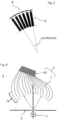
- Fig. 1 shows a device for recording at least one image of a three-dimensional object.
- the device 1 has an optical axis 2, an aperture 3, and a detector 4.
- the three-dimensional object 5 is arranged in front of the aperture 3, and the detector 4 is arranged behind the aperture 3.
- the opening of the aperture 3 is designed such that the spatial distribution of the passing light in the region of the aperture 3 differs depending on the propagation angle.
- the detector 4 is an angle-resolving detector configured to detect the intensity of the light emitted by the three-dimensional object 5 over the angle around the aperture 3.
- a first embodiment of the device 1 in which the detector 4 is formed from several receiving devices 41 arranged concentrically around the aperture To be able to focus exclusively perpendicularly on the detector 4 or the receiving devices 41
- an optical device 6 cf. Fig. 2
- the detector 4 can consist of several tubular apertures arranged side by side; however, other optical elements that absorb or transmit the light accordingly, such as privacy filters or the like, are also possible.
- the detector 4 can be configured to additionally capture color information. For this purpose, the brightness of different colors can be captured using upstream filters.
- the captured image information can be encoded into an electronic file.
- the detector 4 of the device 1 can contain at least one receiving device 41 and optical fibers 7, which are configured to receive image information with their first ends 7a and to guide this to the at least one receiving device 41, which is not located in the beam path of the arrangement.
- the optical fibers 7 are arranged such that they forward the information about the angular distribution of the light incident on them to the at least one receiving device 41.
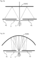
- the device 1 comprises an imaging optics 8 which is configured to uniquely assign the radiation angle at the aperture to a location in the imaging plane, and a detector 4 with at least one flatly arranged receiving device 41.
- an imaging optics 8 can, for example, be at least one planar mirror 81 or a uniformly imaging mirror 82, which is configured to linearly image the angular distribution onto at least one receiving device 41.
- the at least one receiving device 41 can be arranged at an angle to the planar mirror 81.
- digital signal processing can be used to compensate for the angle of incidence of the light rays.
- Fig. 6 shows a device 101 for reproducing at least one image of a three-dimensional object 105 (virtual object), according to a further aspect of the invention.
- the device 101 has an optical axis 102, an aperture 103, and an emitter 120.
- the emitter 120 is an angle-resolving emitter arranged in front of the aperture 103 and configured to emit light, corresponding to a known intensity distribution of the light emitted by a three-dimensional object 5, at an angle to the aperture 103, thereby creating a virtual object 105 on a projection surface behind the aperture 103.
- Fig. 7 shows an embodiment of the device 101 in which the emitter 120 consists of several optical emitter devices 121 which are arranged concentrically around an aperture 103 and radiate light perpendicularly onto the aperture 103.
- the described device 1 for recording at least one image of a three-dimensional object and the device 101 for reproducing at least one image of a three-dimensional object 105 (virtual object) form a recording and reproducing system.
- the recording and reproducing system may further comprise a transmission medium 700 configured to transmit image information from the detector 4 of the recording device 1 to the emitter 120 of the reproducing device 101, which spatially reconstructs the captured image information from the detector 4.
- the transmission medium 700 may, for example, consist of optical fibers 7.
- the transmission medium 700 which may be made of optical fibers 7 (cf. Fig. 8 ), which receives image information with its first end 7a and transmits this image information to its second end 7b, where the image information is emitted in the form of light.
- the optical fibers 7 can be designed as an ordered fiber bundle 77, the fiber ends of which are guided apart on the detector side and on the emitter side and arranged in a planar manner, for example, concentrically around an aperture.
- Fig. 8 A particularly advantageous embodiment is shown in which the ends of the optical fibers 7a and 7b are arranged concentrically around an aperture on both the detector side and the emitter side.
- the optical fibers 7 form the detector 4, the transmission medium 700, and the emitter 120, whereby a virtual image 105 of a three-dimensional object 5 can be reconstructed at a remote location (emitter side).
- the present invention relates, as a further aspect, to a method for recording, transmitting and reconstructing at least one image of a three-dimensional object using the described recording and reproducing device.
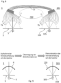
- Fig. 9 describes the method schematically.
- the object 5 is placed in front of a narrow aperture 3, which has such a small opening that one can assume, as a first approximation, that the spatial distribution of the passing light differs primarily due to the propagation angle in the area of the aperture.
- This angular distribution of the light emitted by the object 5 around the aperture 3 is detected by a detector 4 and transmitted to an emitter 120.
- the emitter 120 reconstructs the image by radiating the angular distribution aligned with the aperture 103, whereby a virtual object 105, which corresponds to the original object 5, is created behind the aperture.
- a device 1 with an imaging optics 8 in which the angular distribution can be clearly transformed into a spatial distribution in the imaging plane by means of a transformation.
Landscapes
- Physics & Mathematics (AREA)
- General Physics & Mathematics (AREA)
- Engineering & Computer Science (AREA)
- Signal Processing (AREA)
- Optics & Photonics (AREA)
- Multimedia (AREA)
- Electromagnetism (AREA)
- Computer Networks & Wireless Communication (AREA)
- Length Measuring Devices By Optical Means (AREA)
- Testing, Inspecting, Measuring Of Stereoscopic Televisions And Televisions (AREA)
Claims (10)
- Système d'enregistrement et de reproduction destiné à enregistrer et à reproduire une image d'un objet tridimensionnel, comprenant
un dispositif d'enregistrement (1) destiné à enregistrer au moins une image d'un objet tridimensionnel, dans lequel le dispositif d'enregistrement présente :une ouverture (3) et un détecteur (4), l'objet tridimensionnel (5) étant agencé devant l'ouverture (3), et le détecteur (4), derrière l'ouverture (3) ;dans lequel l'orifice de l'ouverture (3) est réalisé de telle sorte que la lumière passant à travers l'ouverture se distingue de préférence par son angle de propagation ; etde telle sorte que le détecteur (4) est un détecteur de résolution angulaire qui est formé de plusieurs moyens de réception (41) agencés à plat de manière concentrique autour de l'ouverture et qui est configuré pour détecter l'intensité de la lumière émise depuis l'objet tridimensionnel (5) en fonction de l'angle autour de l'ouverture,dans lequel le dispositif d'enregistrement (1) présente en outre un moyen optique (6) qui est configuré pour laisser passer uniquement une lumière incidente perpendiculairement sur le détecteur (4) émise depuis l'objet (5), etun dispositif de reproduction (101) destiné à reproduire au moins une image d'un objet tridimensionnel, le dispositif de reproduction présentant :une surface de projection, une ouverture (103) et un émetteur (120), la surface de projection étant agencée derrière l'ouverture (103), et l'émetteur (120) devant l'ouverture (103) ;dans lequel l'émetteur (120) est un émetteur à résolution angulaire qui se compose de plusieurs moyens émetteurs optiques (121) agencés à plat de manière concentrique autour de l'ouverture (103) et qui est configuré pour émettre de la lumière en correspondance avec une distribution d'intensité connue de la lumière émise depuis l'objet tridimensionnel en fonction d'un angle par rapport à l'ouverture (103), moyennant quoi un objet virtuel (105) apparaît sur la surface de projection. - Système selon l'une quelconque des revendications précédentes, dans lequel le détecteur (4) est configuré pour détecter en supplément des informations de couleur.
- Système selon l'une quelconque des revendications précédentes, dans lequel le détecteur (4) se compose de fibres optiques (7) et d'au moins un moyen de réception (41), les fibres optiques (7) étant configurées pour enregistrer des informations d'image avec leurs premières extrémités (7a) et pour conduire les informations d'image vers ledit au moins un moyen de réception (41).
- Système selon l'une quelconque des revendications précédentes, comprenant en outre un support de transmission (700),dans lequel le support de transmission (700) est configuré pour transmettre des informations d'image depuis le détecteur (4) du dispositif d'enregistrement (1) jusqu'à un émetteur (120) du dispositif de reproduction (101), etdans lequel l'émetteur (120) est configuré pour reconstruire dans l'espace les informations d'image qui lui sont transmises via le support de transmission (700) en correspondance avec la distribution angulaire détectée.
- Système selon la revendication 4, dans lequel des fibres optiques (7) forment le détecteur (4), le support de transmission (700) et l'émetteur (120), en étant configurées pour recevoir les informations d'image avec leur première extrémité (7a) et en transmettant ces informations d'image au niveau de leur seconde extrémité (7b) et en émettant les informations d'image au niveau de leur seconde extrémité, et dans lequel les fibres optiques (7) présentent une faible ouverture numérique de sorte que seule une lumière incidente pratiquement perpendiculaire est détectée et guidée jusqu'audit au moins un moyen de réception (41).
- Système selon la revendication 5, dans lequel les fibres optiques (7) sont réalisées sous la forme d'un faisceau de fibres ordonné (77), dans lequel les extrémités de fibres (7a ; 7b) sont écartées les unes des autres et sont agencées à plat.
- Système selon la revendication 6, dans lequel les extrémités de fibres (7a ; 7b) du faisceau de fibres (77) sont agencées à plat de manière concentrique autour d'une ouverture (3 ; 103).
- Appareil terminal de télécommunication, caractérisé en ce que l'appareil terminal présente un système selon l'une quelconque des revendications précédentes.
- Procédé d'enregistrement, de transmission et de reconstruction d'au moins une image d'un objet tridimensionnel, comprenant un système d'enregistrement et de reproduction selon l'une quelconque des revendications 1 à 8, le procédé comprenant les étapes suivantes consistant à :(1) enregistrer des informations d'image de la lumière émise depuis un objet tridimensionnel (5) à l'aide du détecteur (4), les informations d'image comprenant la distribution angulaire de la lumière émise depuis l'objet (5) autour de l'ouverture (3) ;(2) transmettre à l'émetteur (120) les informations d'image détectées ;(3) reconstruire l'image au moyen de l'émetteur (120) en tenant compte de la distribution angulaire détectée et transmise.
- Procédé selon la revendication 9, dans lequel la distribution angulaire est en outre transformée en une distribution spatiale dans le plan de représentation.
Priority Applications (1)
| Application Number | Priority Date | Filing Date | Title |
|---|---|---|---|
| EP18167203.1A EP3553590B1 (fr) | 2018-04-13 | 2018-04-13 | Dispositif et procédé d'enregistrement, de transmission et de reconstruction spatiale d'images d'objets tridimensionnels |
Applications Claiming Priority (1)
| Application Number | Priority Date | Filing Date | Title |
|---|---|---|---|
| EP18167203.1A EP3553590B1 (fr) | 2018-04-13 | 2018-04-13 | Dispositif et procédé d'enregistrement, de transmission et de reconstruction spatiale d'images d'objets tridimensionnels |
Publications (2)
| Publication Number | Publication Date |
|---|---|
| EP3553590A1 EP3553590A1 (fr) | 2019-10-16 |
| EP3553590B1 true EP3553590B1 (fr) | 2025-05-28 |
Family
ID=62002539
Family Applications (1)
| Application Number | Title | Priority Date | Filing Date |
|---|---|---|---|
| EP18167203.1A Active EP3553590B1 (fr) | 2018-04-13 | 2018-04-13 | Dispositif et procédé d'enregistrement, de transmission et de reconstruction spatiale d'images d'objets tridimensionnels |
Country Status (1)
| Country | Link |
|---|---|
| EP (1) | EP3553590B1 (fr) |
Family Cites Families (12)
| Publication number | Priority date | Publication date | Assignee | Title |
|---|---|---|---|---|
| US3647284A (en) | 1970-11-30 | 1972-03-07 | Virgil B Elings | Optical display device |
| US3912856A (en) | 1972-03-27 | 1975-10-14 | William S Liddel | Three-dimensional image transmitting apparatus |
| US4650279A (en) * | 1984-08-15 | 1987-03-17 | The Charles Stark Draper Laboratory, Inc. | Fiber optic lens |
| DE10162846A1 (de) * | 2001-12-20 | 2003-07-03 | Horst Scharf | Lochkamera |
| DE102005013558A1 (de) | 2005-03-23 | 2006-09-28 | Carl Zeiss Meditec Ag | Verfahren und Vorrichtung zur Erhöhung der Tiefenschärfe eines optischen Systems |
| JP2010088092A (ja) | 2008-09-02 | 2010-04-15 | Panasonic Corp | 立体映像伝送システム、映像表示装置および映像出力装置 |
| DE102009012664A1 (de) | 2009-03-13 | 2010-09-16 | T-Mobile International Ag | Vorrichtung zur Aufnahme, Fernübertragung und Wiedergabe dreidemensionaler Bilder |
| TW201116041A (en) | 2009-06-29 | 2011-05-01 | Sony Corp | Three-dimensional image data transmission device, three-dimensional image data transmission method, three-dimensional image data reception device, three-dimensional image data reception method, image data transmission device, and image data reception |
| CN103592811A (zh) * | 2012-08-14 | 2014-02-19 | 张培洲 | 反射式针孔摄影镜头 |
| JP6338467B2 (ja) * | 2014-06-18 | 2018-06-06 | キヤノン株式会社 | 撮像装置 |
| US10511787B2 (en) | 2015-02-12 | 2019-12-17 | Fraunhofer-Gesellschaft Zur Foerderung Der Angewandten Forschung E.V. | Light-field camera |
| US10565734B2 (en) * | 2015-04-15 | 2020-02-18 | Google Llc | Video capture, processing, calibration, computational fiber artifact removal, and light-field pipeline |
-
2018
- 2018-04-13 EP EP18167203.1A patent/EP3553590B1/fr active Active
Also Published As
| Publication number | Publication date |
|---|---|
| EP3553590A1 (fr) | 2019-10-16 |
Similar Documents
| Publication | Publication Date | Title |
|---|---|---|
| EP2395392B1 (fr) | Objectif de caméra et système de caméra avec un masque pour déterminer des informations de profondeur | |
| EP3293558B1 (fr) | Dispositif de détection d'une image stéréo | |
| DE102010017543A1 (de) | Vorrichtung und Verfahren zur kombinierten optischen und nuklearen Bilderfassung | |
| EP2011331B1 (fr) | Système de saisie d'image fournissant une vue panoramique | |
| EP0907902B1 (fr) | Procede de representation visuelle tridimensionnelle sur une surface de projection a grand ecran a l'aide d'un projecteur a laser | |
| DE102015011427B4 (de) | Bildaufnahmesystem und Bildauswertesystem | |
| DE102009008747B4 (de) | Optisches Abbildungssystem | |
| DE102015224185A1 (de) | Vorrichtung zum Erfassen und Anzeigen einer Fahrzeugumgebung in einem Fahrzeug | |
| EP3553590B1 (fr) | Dispositif et procédé d'enregistrement, de transmission et de reconstruction spatiale d'images d'objets tridimensionnels | |
| WO2022195099A1 (fr) | Système de caméra pour générer une image optique ininterrompue | |
| EP4217785B1 (fr) | Système d'imagerie, en particulier pour une caméra | |
| WO2008000443A1 (fr) | Représentation d'images optiques sur un capteur d'image au moyen d'une plaque à fibres optiques ou d'un coin sensitométrique de fibre | |
| DE60037040T2 (de) | Panoramische stereokamera-anordungen zur aufnahme panoramischer bilder für einpanoramisches stereobild-paar | |
| DE102012020922A1 (de) | Laserscanner | |
| LU102086B1 (de) | Verfahren zur Erstellung einer Bildaufzeichnung | |
| DE19542355A1 (de) | Verfahren und Vorrichtung zur Erzeugung eines Weitwinkelbildes | |
| EP4217958B1 (fr) | Procédé de création d'un enregistrement d'image | |
| DE4405531C2 (de) | Verfahren und Vorrichtung zur Erfassung der Geometrie räumlicher Objekte | |
| WO2015197701A1 (fr) | Dispositif de projection et procédé de génération d'une image de projection | |
| DE102014105222A1 (de) | Kamera mit integriertem Spektrometer | |
| DE69026084T2 (de) | Videosucher, optisch gekoppelt mit Fasern | |
| DE102017118437A1 (de) | Empfängereinheit für eine Laserabtastvorrichtung, Laserabtastvorrichtung, Fahrzeug und Verfahren zum Erfassen von Licht | |
| DE1953352C (de) | Ziel- und Beobachtungseinrichtung mit zwei elektrooptischen Beobachtungsgeräten | |
| DE102020210001A1 (de) | Anordnung zum erzeugen einer optischen abbildung sowie ein kamerasystem | |
| DE1274627B (de) | Anordnung in einer Farbfernsehkamera mit mehreren Bildaufnahmeroehren |
Legal Events
| Date | Code | Title | Description |
|---|---|---|---|
| PUAI | Public reference made under article 153(3) epc to a published international application that has entered the european phase |
Free format text: ORIGINAL CODE: 0009012 |
|
| STAA | Information on the status of an ep patent application or granted ep patent |
Free format text: STATUS: REQUEST FOR EXAMINATION WAS MADE |
|
| 17P | Request for examination filed |
Effective date: 20190502 |
|
| AK | Designated contracting states |
Kind code of ref document: A1 Designated state(s): AL AT BE BG CH CY CZ DE DK EE ES FI FR GB GR HR HU IE IS IT LI LT LU LV MC MK MT NL NO PL PT RO RS SE SI SK SM TR |
|
| AX | Request for extension of the european patent |
Extension state: BA ME |
|
| STAA | Information on the status of an ep patent application or granted ep patent |
Free format text: STATUS: EXAMINATION IS IN PROGRESS |
|
| 17Q | First examination report despatched |
Effective date: 20210719 |
|
| REG | Reference to a national code |
Ref country code: DE Ref legal event code: R079 Free format text: PREVIOUS MAIN CLASS: G02B0027220000 Ipc: G02B0030560000 Ref country code: DE Ref legal event code: R079 Ref document number: 502018015841 Country of ref document: DE Free format text: PREVIOUS MAIN CLASS: G02B0027220000 Ipc: G02B0030560000 |
|
| GRAP | Despatch of communication of intention to grant a patent |
Free format text: ORIGINAL CODE: EPIDOSNIGR1 |
|
| STAA | Information on the status of an ep patent application or granted ep patent |
Free format text: STATUS: GRANT OF PATENT IS INTENDED |
|
| RIC1 | Information provided on ipc code assigned before grant |
Ipc: H04N 13/32 20180101ALI20240821BHEP Ipc: H04N 13/236 20180101ALI20240821BHEP Ipc: H04B 10/25 20130101ALI20240821BHEP Ipc: G03B 35/08 20060101ALI20240821BHEP Ipc: G02B 6/06 20060101ALI20240821BHEP Ipc: G03B 19/16 20060101ALI20240821BHEP Ipc: G02B 30/56 20200101AFI20240821BHEP |
|
| INTG | Intention to grant announced |
Effective date: 20240924 |
|
| RIN1 | Information on inventor provided before grant (corrected) |
Inventor name: BUNGE, CHRISTIAN-ALEXANDER |
|
| GRAJ | Information related to disapproval of communication of intention to grant by the applicant or resumption of examination proceedings by the epo deleted |
Free format text: ORIGINAL CODE: EPIDOSDIGR1 |
|
| STAA | Information on the status of an ep patent application or granted ep patent |
Free format text: STATUS: EXAMINATION IS IN PROGRESS |
|
| GRAS | Grant fee paid |
Free format text: ORIGINAL CODE: EPIDOSNIGR3 |
|
| STAA | Information on the status of an ep patent application or granted ep patent |
Free format text: STATUS: GRANT OF PATENT IS INTENDED |
|
| GRAP | Despatch of communication of intention to grant a patent |
Free format text: ORIGINAL CODE: EPIDOSNIGR1 |
|
| INTC | Intention to grant announced (deleted) | ||
| INTG | Intention to grant announced |
Effective date: 20250128 |
|
| GRAA | (expected) grant |
Free format text: ORIGINAL CODE: 0009210 |
|
| STAA | Information on the status of an ep patent application or granted ep patent |
Free format text: STATUS: THE PATENT HAS BEEN GRANTED |
|
| AK | Designated contracting states |
Kind code of ref document: B1 Designated state(s): AL AT BE BG CH CY CZ DE DK EE ES FI FR GB GR HR HU IE IS IT LI LT LU LV MC MK MT NL NO PL PT RO RS SE SI SK SM TR |
|
| REG | Reference to a national code |
Ref country code: GB Ref legal event code: FG4D Free format text: NOT ENGLISH |
|
| REG | Reference to a national code |
Ref country code: CH Ref legal event code: EP |
|
| REG | Reference to a national code |
Ref country code: IE Ref legal event code: FG4D Free format text: LANGUAGE OF EP DOCUMENT: GERMAN Ref country code: DE Ref legal event code: R096 Ref document number: 502018015841 Country of ref document: DE |
|
| REG | Reference to a national code |
Ref country code: NL Ref legal event code: MP Effective date: 20250528 |
|
| PG25 | Lapsed in a contracting state [announced via postgrant information from national office to epo] |
Ref country code: FI Free format text: LAPSE BECAUSE OF FAILURE TO SUBMIT A TRANSLATION OF THE DESCRIPTION OR TO PAY THE FEE WITHIN THE PRESCRIBED TIME-LIMIT Effective date: 20250528 Ref country code: ES Free format text: LAPSE BECAUSE OF FAILURE TO SUBMIT A TRANSLATION OF THE DESCRIPTION OR TO PAY THE FEE WITHIN THE PRESCRIBED TIME-LIMIT Effective date: 20250528 |
|
| REG | Reference to a national code |
Ref country code: LT Ref legal event code: MG9D |
|
| PG25 | Lapsed in a contracting state [announced via postgrant information from national office to epo] |
Ref country code: GR Free format text: LAPSE BECAUSE OF FAILURE TO SUBMIT A TRANSLATION OF THE DESCRIPTION OR TO PAY THE FEE WITHIN THE PRESCRIBED TIME-LIMIT Effective date: 20250829 Ref country code: NO Free format text: LAPSE BECAUSE OF FAILURE TO SUBMIT A TRANSLATION OF THE DESCRIPTION OR TO PAY THE FEE WITHIN THE PRESCRIBED TIME-LIMIT Effective date: 20250828 |
|
| PG25 | Lapsed in a contracting state [announced via postgrant information from national office to epo] |
Ref country code: NL Free format text: LAPSE BECAUSE OF FAILURE TO SUBMIT A TRANSLATION OF THE DESCRIPTION OR TO PAY THE FEE WITHIN THE PRESCRIBED TIME-LIMIT Effective date: 20250528 Ref country code: PL Free format text: LAPSE BECAUSE OF FAILURE TO SUBMIT A TRANSLATION OF THE DESCRIPTION OR TO PAY THE FEE WITHIN THE PRESCRIBED TIME-LIMIT Effective date: 20250528 |
|
| PG25 | Lapsed in a contracting state [announced via postgrant information from national office to epo] |
Ref country code: BG Free format text: LAPSE BECAUSE OF FAILURE TO SUBMIT A TRANSLATION OF THE DESCRIPTION OR TO PAY THE FEE WITHIN THE PRESCRIBED TIME-LIMIT Effective date: 20250528 |
|
| PG25 | Lapsed in a contracting state [announced via postgrant information from national office to epo] |
Ref country code: HR Free format text: LAPSE BECAUSE OF FAILURE TO SUBMIT A TRANSLATION OF THE DESCRIPTION OR TO PAY THE FEE WITHIN THE PRESCRIBED TIME-LIMIT Effective date: 20250528 |
|
| PG25 | Lapsed in a contracting state [announced via postgrant information from national office to epo] |
Ref country code: RS Free format text: LAPSE BECAUSE OF FAILURE TO SUBMIT A TRANSLATION OF THE DESCRIPTION OR TO PAY THE FEE WITHIN THE PRESCRIBED TIME-LIMIT Effective date: 20250828 |
|
| PG25 | Lapsed in a contracting state [announced via postgrant information from national office to epo] |
Ref country code: IS Free format text: LAPSE BECAUSE OF FAILURE TO SUBMIT A TRANSLATION OF THE DESCRIPTION OR TO PAY THE FEE WITHIN THE PRESCRIBED TIME-LIMIT Effective date: 20250928 |
|
| PG25 | Lapsed in a contracting state [announced via postgrant information from national office to epo] |
Ref country code: LV Free format text: LAPSE BECAUSE OF FAILURE TO SUBMIT A TRANSLATION OF THE DESCRIPTION OR TO PAY THE FEE WITHIN THE PRESCRIBED TIME-LIMIT Effective date: 20250528 |
|
| PG25 | Lapsed in a contracting state [announced via postgrant information from national office to epo] |
Ref country code: DK Free format text: LAPSE BECAUSE OF FAILURE TO SUBMIT A TRANSLATION OF THE DESCRIPTION OR TO PAY THE FEE WITHIN THE PRESCRIBED TIME-LIMIT Effective date: 20250528 Ref country code: SM Free format text: LAPSE BECAUSE OF FAILURE TO SUBMIT A TRANSLATION OF THE DESCRIPTION OR TO PAY THE FEE WITHIN THE PRESCRIBED TIME-LIMIT Effective date: 20250528 |
|
| PG25 | Lapsed in a contracting state [announced via postgrant information from national office to epo] |
Ref country code: CZ Free format text: LAPSE BECAUSE OF FAILURE TO SUBMIT A TRANSLATION OF THE DESCRIPTION OR TO PAY THE FEE WITHIN THE PRESCRIBED TIME-LIMIT Effective date: 20250528 |
|
| PG25 | Lapsed in a contracting state [announced via postgrant information from national office to epo] |
Ref country code: EE Free format text: LAPSE BECAUSE OF FAILURE TO SUBMIT A TRANSLATION OF THE DESCRIPTION OR TO PAY THE FEE WITHIN THE PRESCRIBED TIME-LIMIT Effective date: 20250528 |
|
| PG25 | Lapsed in a contracting state [announced via postgrant information from national office to epo] |
Ref country code: RO Free format text: LAPSE BECAUSE OF FAILURE TO SUBMIT A TRANSLATION OF THE DESCRIPTION OR TO PAY THE FEE WITHIN THE PRESCRIBED TIME-LIMIT Effective date: 20250528 Ref country code: SK Free format text: LAPSE BECAUSE OF FAILURE TO SUBMIT A TRANSLATION OF THE DESCRIPTION OR TO PAY THE FEE WITHIN THE PRESCRIBED TIME-LIMIT Effective date: 20250528 |
|
| PG25 | Lapsed in a contracting state [announced via postgrant information from national office to epo] |
Ref country code: IT Free format text: LAPSE BECAUSE OF FAILURE TO SUBMIT A TRANSLATION OF THE DESCRIPTION OR TO PAY THE FEE WITHIN THE PRESCRIBED TIME-LIMIT Effective date: 20250528 |