EP0907902B1 - Procede de representation visuelle tridimensionnelle sur une surface de projection a grand ecran a l'aide d'un projecteur a laser - Google Patents
Procede de representation visuelle tridimensionnelle sur une surface de projection a grand ecran a l'aide d'un projecteur a laser Download PDFInfo
- Publication number
- EP0907902B1 EP0907902B1 EP97931632A EP97931632A EP0907902B1 EP 0907902 B1 EP0907902 B1 EP 0907902B1 EP 97931632 A EP97931632 A EP 97931632A EP 97931632 A EP97931632 A EP 97931632A EP 0907902 B1 EP0907902 B1 EP 0907902B1
- Authority
- EP
- European Patent Office
- Prior art keywords
- polarization
- lines
- mirror
- laser beam
- projection surface
- Prior art date
- Legal status (The legal status is an assumption and is not a legal conclusion. Google has not performed a legal analysis and makes no representation as to the accuracy of the status listed.)
- Expired - Lifetime
Links
Images
Classifications
-
- H—ELECTRICITY
- H04—ELECTRIC COMMUNICATION TECHNIQUE
- H04N—PICTORIAL COMMUNICATION, e.g. TELEVISION
- H04N5/00—Details of television systems
- H04N5/74—Projection arrangements for image reproduction, e.g. using eidophor
-
- H—ELECTRICITY
- H04—ELECTRIC COMMUNICATION TECHNIQUE
- H04N—PICTORIAL COMMUNICATION, e.g. TELEVISION
- H04N13/00—Stereoscopic video systems; Multi-view video systems; Details thereof
- H04N13/30—Image reproducers
- H04N13/324—Colour aspects
-
- H—ELECTRICITY
- H04—ELECTRIC COMMUNICATION TECHNIQUE
- H04N—PICTORIAL COMMUNICATION, e.g. TELEVISION
- H04N13/00—Stereoscopic video systems; Multi-view video systems; Details thereof
- H04N13/30—Image reproducers
- H04N13/332—Displays for viewing with the aid of special glasses or head-mounted displays [HMD]
- H04N13/337—Displays for viewing with the aid of special glasses or head-mounted displays [HMD] using polarisation multiplexing
-
- H—ELECTRICITY
- H04—ELECTRIC COMMUNICATION TECHNIQUE
- H04N—PICTORIAL COMMUNICATION, e.g. TELEVISION
- H04N13/00—Stereoscopic video systems; Multi-view video systems; Details thereof
- H04N13/30—Image reproducers
- H04N13/363—Image reproducers using image projection screens
-
- H—ELECTRICITY
- H04—ELECTRIC COMMUNICATION TECHNIQUE
- H04N—PICTORIAL COMMUNICATION, e.g. TELEVISION
- H04N13/00—Stereoscopic video systems; Multi-view video systems; Details thereof
- H04N13/30—Image reproducers
- H04N13/398—Synchronisation thereof; Control thereof
Definitions
- the invention relates to methods for three-dimensional image display on a large screen projection surface using a Laser projector according to the preambles of claims 1 and 3rd
- a laser projector is for two-dimensional representation of graphics etc. usable.
- a color laser projector is light of the colors red, green and blue generated three lasers. The rays of light become through you rotating polygon mirror deflected horizontally. The horizontal Distraction allows the display of a screen line. After the horizontal distraction is followed by another rotating mirror a vertical distraction. To this The image is displayed on a large-screen projection surface using optics projected.
- a laser projector thus enables the display of very large images with particularly brilliant ones Colours.
- a color laser projector has three lasers for the colors Red, green and blue on, but the laser principle is common to everyone three colors the same. It will only be for an individual The different pixels on the large-screen projection surface Colors for a corresponding overall color required overlaid.
- the laser beams generated by single-mode lasers have a single polarization direction. she have a linearly polarized light. In contrast, they have Circularly polarized laser beams generated by multimode lasers Light, i.e. they have more than one direction of polarization. For example, they have 2, 4, etc. various Directions of polarization. In extreme cases, their polarizations scatter in all directions.
- the object of the invention is to provide methods for three-dimensional Image display on a large-screen projection surface using the principle of operation of a laser projector.
- the multimode laser beam is directed in two different directions each alternating light-polarizing mirror parts thrown of the polygon mirror. From the mirror parts of the polygon mirror are made according to the alternating light-polarizing mirror parts on the large-screen projection surface alternately lines with one and lines written with the other direction of polarization. Moreover is controlling the multimode laser beam in the way executed that in each case on the large-screen projection surface first picture only with the lines of one polarization direction and a second image only with the lines of the other polarization direction arises. Both have two pictures the property of being viewed by a viewer with a Glasses with a first lens for one and with one second lens for the other direction of polarization can be summarized in a three-dimensional overall picture
- the partially transparent mirror serves as a distraction of a partial beam of the single-mode laser beam.
- the distracted and possibly rotated partial beam is made from a opposite the first direction second direction to respective associated second mirror parts of the polygon mirror for a distraction to the second lines of each successive first and second lines of the large-screen projection surface directed.
- the control of the single-mode laser beam takes place in such a way that on the large screen projection surface always a first picture with the rotated / unrotated Direction of polarization on the first Lines and a second image with the unrotated / rotated polarization direction on the second lines of the large screen projection area arises.
- the two generated each Pictures have the property that they are from a viewer with glasses with a first lens for one and with a second lens for the other polarization direction can be summarized in a three-dimensional overall picture are.
- Both methods thus enable the viewer to see the three-dimensional one see on a large-screen projection surface using the principle of operation of a laser projector.
- the partially transparent mirror has a transparency of 50% on, have received after the partially transparent mirror and the deflected laser beam each have the same energy output.
- the two partial laser beams can still be used therefore particularly easy, since an adjustment of the energy performance to each other.
- the large-screen projection surface is used to generate the two images Scanned line by line.
- momomode laser principle is used to write the first lines of the laser beam from one direction and for writing each second lines of laser beam from the other direction used.
- the Laser beam for writing on the other lines directed an absorption surface becomes an associated device not illuminated and heated on the inside. Will the laser beam Steered onto a photovoltaic panel can lead to some Degrees of energy can be recovered from the laser beam.
- lasers L are one for each Colors red, green and blue provided. Each of these lasers L but works on the principle shown, so that on this Place only one laser L must be shown at a time.
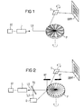
- FIGS 1 and 2 are for understanding the invention necessary basic parts of a laser projector shown.
- Laser L which emits a laser beam LS
- a polygon mirror P who is responsible for horizontal laser beam deflection is
- another mirror S which is used for vertical laser beam deflection is responsible
- a controller ST for the Control of the laser beam LS emitted by the laser L.
- the person responsible for the horizontal deflection of the laser beam LS Polygon mirror P rotates around an axis. The rotation is by a corresponding arrow around the relevant axis indicated.
- the further mirror S pivots in the exemplary embodiment back and forth, also indicated by a corresponding one Arrow around the corresponding axis.
- the laser L is a multimode laser
- the laser L in FIG. 2 is a single-mode laser.
- the basic principle of a laser projector is that of a laser L generated laser beam LS thrown onto the polygon mirror P. becomes.
- the polygon mirror P consists of many, e.g. 32 Mirror parts, each for one line of a large-screen projection surface GBPF are responsible.
- the mirror parts are from Circumferential course seen sawtooth-shaped. This is coming therefore, because the mirror parts like the blades of an airscrew are arranged and each have an angle of attack.
- the laser beam LS hits a mirror part in each case of the page.
- By rotating the polygon mirror P and the respective inclined mirror part of the Laser beam LS next to a beam deflection a linear one Beam movement in the deflected part of the beam.
- By redirecting the linearly moving beam part of the laser beam LS through the another mirror S onto the large-screen projection surface GBPF can thus line up the large-screen projection surface GBPF can be described.
- the laser beam LS thrown onto a polygon mirror P whose mirror parts alternate in two polarization directions has light-polarizing layers. In the figure 1 this is by alternately hatched and not hatched areas. Since the laser beam LS Is multimode laser beam, this can be directly on the polygon mirror P be directed. From the multimode laser beam are the polarization directions through the polygon mirror P filtered out the polarization directions correspond to the polarizing layers of the mirror surfaces.
- a multimode laser is favorably used right from the start, which has only these two polarization directions, because then an optimal energy balance through minimal energy losses is achieved.
- the coated polygon mirror P makes the first Lines of consecutive first and second Lines of the large-screen projection area GBPF with one polarization direction and the second lines with the other Direction of polarization described. In Figure 1 is this is illustrated by thicker and thinner lines.
- Control of the laser beam takes place via the control ST LS such that on the large-screen projection surface GBPF each a first picture only with the lines of one polarization direction and a second picture only with the lines of the other
- the direction of polarization arises, producing such images should be that of a viewer with glasses a first lens for one and with a second Glasses for the other polarization direction the pictures from the content to a meaningful three-dimensional overall picture can be summarized with the present laser projector realized a three-dimensional image become.
- the principle of Figure 1 cannot be applied because the laser beam LS due to the different polarizing Coatings of the mirror parts of the polygon mirror P once is forwarded, the other time because of mismatching Direction of polarization between the laser beam LS and the coating is absorbed.
- the laser beam LS through a partially transparent one Mirror TS steered before it on the polygon mirror P is directed.
- the polygon mirror P does not need any light polarizing layer.
- the mirror parts are simple mirrors.
- the partially transparent mirror TS guides a partial beam TSL from.
- the partially transparent mirror advantageously has TS a transparency of 50%, so that the partial beam TSL and the one that still passes through the partially transparent mirror TS Laser beam each have an energy share of 50%.
- the partial beam TSL is directed into a rotating device D.
- the rotating device D becomes the polarization direction of the Partial beam TSL preferably rotated by 90 degrees.
- the partial beam TSL is then on the polygon mirror P from a different direction than the unrotated laser beam directed to the semi-transparent mirror TS.
- the rotated or not rotated Mirror parts of the polygon mirror belonging to laser beams P can thus on the large screen projection surface GBPF in the same way as in FIG. 1 in each case first Lines with one direction of polarization and each second lines with the other direction of polarization become.
- you can use two pictures each are generated with different polarization directions, that of a viewer with a corresponding one already above addressed glasses to a three-dimensional image can be summarized.
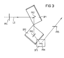
- FIG. 3 shows a possible construction of a rotating device D shown.
- the laser beam LS comes with a Polarization direction PR1 on and is on a first mirror SP1 steered. This is, for example, with an x-y-z spatial coordinate -45 °, -45 °, 0 ° set.
- the first mirror Spl rotates the polarization direction PR1 in the polarization direction PR2.
- the laser beam LS is from the first mirror SP1 to a second mirror SP2, for example the spatial coordinates 0 °, 45 °, -45 °.
- the second mirror SP2 rotates the direction of polarization PR2 in the direction of polarization PR3.
- the laser beam LS is from the second mirror SP2 to a third mirror SP3, for example the spatial coordinates -90 °, a °, 0 °.
- the third mirror SP3 rotates the polarization direction PR3 in a polarization direction PR4, which is simultaneously the radiation polarization direction PR5 corresponds with that of the laser beam LS on the polygon mirror P is steered.
- The is advantageously difference between the polarization directions PR1 and PR5 90 degrees.
- GBPF is not exclusive to understand a relatively large area. This can occur in individual cases also have small dimensions.
Claims (6)
- Procédé de représentation d'image en trois dimensions sur une surface (GBPF) de projection à grande image au moyen du principe de fonctionnement d'un projecteur à laser comportant un miroir (P) polygonal tournant pour le balayage horizontal et comportant au moins un laser (L) fournissant un faisceau (LS) laser multimode, caractérisé en ce que le faisceau (LS) laser multimode est envoyé depuis le côté sur des parties réfléchissantes du miroir (P) polygonal qui polarisent la lumière alternativement dans deux directions différentes, qui sont disposées comme les pales d'une hélice d'avion, qui ont chacune un angle d'incidence et à partir desquelles, suivant les parties réfléchissantes qui polarisent la lumière de manière alternée et dont l'angle d'incidence est réglé, on écrit sur la surface (GBPF) de projection à grande image en alternance des lignes ayant l'une des directions de polarisation et des lignes ayant l'autre direction de polarisation, et en ce que la commande du faisceau (LS) laser multimode s'effectue de telle manière que l'on produit sur la surface (GBPF) de projection à grande image une première image n'ayant que les lignes de l'une des directions de polarisation et une deuxième image n'ayant que les lignes de l'autre direction de polarisation avec la propriété associée qu'elles peuvent être réunies en une image totale tridimensionnelle par un observateur ayant des lunettes ayant un premier verre de lunette pour l'une des direction de polarisation et un deuxième verre de lunette pour l'autre direction de polarisation.
- Procédé suivant la revendication 1, caractérisé en ce que les images produites en ayant deux directions de polarisation différentes sont produites en ayant des directions de polarisation différentes de 90°.
- Procédé pour la représentation d'images tridimensionnelles sur une surface (GBPF) de projection à grande image au moyen du principe de fonctionnement d'un projecteur à laser comportant un miroir (P) polygonal tournant pour le balayage de lignes et comportant au moins un laser (L) fournissant un faisceau (LS) laser monomode, caractérisé en ce que le faisceau (LS) laser monomode est, avant l'arrivée depuis une première direction à de premières parties réfléchissantes associées du miroir (P) polygonal pour une déviation vers de premières lignes de première et deuxième lignes qui se succèdent de la surface (GBPF) de projection à grande image, envoyé par un miroir (TS) semi transparent servant à la déviation d'un sous-faisceau (TSL), en ce que, au choix, le sous-faisceau (TSL) dévié ou du faisceau (LS) laser monomode non dévié est tourné en aval du miroir (TS) semi transparent dans sa direction de polarisation, en ce que le sous-faisceau (TSL) dévié et éventuellement tourné est envoyé, à partir d'une deuxième direction modifiée par rapport à la première direction, à des deuxièmes parties réfléchissantes associées du miroir (P) polygonal pour une déviation vers les deuxièmes lignes de premières et deuxièmes lignes qui se succèdent de la surface (GBPF) de projection à grande image, et en ce que la commande du faisceau (LS) laser monomode s'effectue de telle manière qu'il est produit sur la surface (GBPF) de projection à grande image une première image avec la direction de polarisation tournée/non tournée sur les premières lignes et une deuxième image avec la direction de polarisation non tournée/tournée sur les deuxièmes lignes de la surface (GBPF) de projection à grande image, avec la propriété associée qu'elles peuvent être réunies en une image totale tridimensionnelle par un observateur ayant des lunettes ayant un premier verre de lunette pour l'une des directions de polarisation et ayant un deuxième verre de lunette pour l'autre direction de polarisation.
- Procédé suivant la revendication 3, caractérisé en ce que le faisceau (LS) laser monomode est guidé par un miroir (TS) semi transparent ayant une transparence de 50 %.
- Procédé suivant la revendication 3 ou 4, caractérisé en ce que la rotation du faisceau (LS) laser par des miroirs est de 90°.
- Procédé suivant l'une des revendications 3 à 5, caractérisé en ce que le faisceau (LS) laser qui n'est pas associé à des parties réfléchissantes déterminées du faisceau (P) polygonal est envoyé à une surface d'absorption ou à une plaque (AP) photovoltaïque.
Applications Claiming Priority (3)
| Application Number | Priority Date | Filing Date | Title |
|---|---|---|---|
| DE19626096A DE19626096C1 (de) | 1996-06-28 | 1996-06-28 | Verfahren zur dreidimensionalen Bilddarstellung auf einer Großbildprojektionsfläche mittels eines Laser-Projektors |
| DE19626096 | 1996-06-28 | ||
| PCT/DE1997/001286 WO1998000748A1 (fr) | 1996-06-28 | 1997-06-19 | Procede de representation visuelle tridimensionnelle sur une surface de projection a grand ecran a l'aide d'un projecteur a laser |
Publications (2)
| Publication Number | Publication Date |
|---|---|
| EP0907902A1 EP0907902A1 (fr) | 1999-04-14 |
| EP0907902B1 true EP0907902B1 (fr) | 2000-08-30 |
Family
ID=7798372
Family Applications (1)
| Application Number | Title | Priority Date | Filing Date |
|---|---|---|---|
| EP97931632A Expired - Lifetime EP0907902B1 (fr) | 1996-06-28 | 1997-06-19 | Procede de representation visuelle tridimensionnelle sur une surface de projection a grand ecran a l'aide d'un projecteur a laser |
Country Status (7)
| Country | Link |
|---|---|
| US (1) | US6109750A (fr) |
| EP (1) | EP0907902B1 (fr) |
| JP (1) | JP2000514201A (fr) |
| AT (1) | ATE196016T1 (fr) |
| DE (2) | DE19626096C1 (fr) |
| ES (1) | ES2151738T3 (fr) |
| WO (1) | WO1998000748A1 (fr) |
Families Citing this family (16)
| Publication number | Priority date | Publication date | Assignee | Title |
|---|---|---|---|---|
| GB9811695D0 (en) * | 1998-06-01 | 1998-07-29 | Tricorder Technology Plc | Facial image processing method and apparatus |
| US6719719B2 (en) | 1998-11-13 | 2004-04-13 | Elan Pharma International Limited | Spike for liquid transfer device, liquid transfer device including spike, and method of transferring liquids using the same |
| AU2001236798B2 (en) | 2000-02-08 | 2004-11-04 | Rice University | Optically-active nanoparticles for use in therapeutic and diagnostic methods |
| EP1405264A4 (fr) * | 2000-11-03 | 2005-08-17 | Actuality Systems Inc | Systemes d'affichage tridimensionnel |
| KR20020073054A (ko) * | 2001-03-14 | 2002-09-19 | 한국과학기술연구원 | 다층영상 표현시스템 및 그 방법 |
| DE10135418B4 (de) * | 2001-07-20 | 2004-07-15 | Jenoptik Ldt Gmbh | Rasterprojektion eines Bildes mit hin- und hergehender Lichtstrahlführung |
| GB2382881A (en) * | 2001-12-10 | 2003-06-11 | Wynne Willson Gottelier Ltd | Digital image projector with deflector array |
| US7184104B2 (en) * | 2002-05-03 | 2007-02-27 | Hewlett-Packard Development Company, L.P. | Projector having scanning optics |
| US20040109480A1 (en) * | 2002-12-06 | 2004-06-10 | Vandruff Dean | Atmosperic light beam projection apparatus and method |
| DE10332275B4 (de) * | 2003-07-10 | 2005-05-04 | Deutsches Zentrum für Luft- und Raumfahrt e.V. | Panorama-Bildprojektor |
| US20050093818A1 (en) * | 2003-11-05 | 2005-05-05 | Lightbay Networks Corporation | Dynamic laser projection display |
| WO2005092286A2 (fr) * | 2004-03-29 | 2005-10-06 | The University Of Houston System | Nouvelles nanoparticules et nanoparticules discretes couchees polymere, methodes de production et d'utilisation des nanoparticules |
| JP2006047421A (ja) * | 2004-07-30 | 2006-02-16 | Canon Inc | 表示光学系および画像投射装置 |
| US20100231868A1 (en) * | 2009-03-13 | 2010-09-16 | Alvis Technologies Inc. | Display device |
| US20130176407A1 (en) * | 2012-01-05 | 2013-07-11 | Reald Inc. | Beam scanned display apparatus and method thereof |
| CN104297928B (zh) * | 2013-07-15 | 2017-03-01 | 台达电子工业股份有限公司 | 立体显示装置与应用其的投影方法 |
Family Cites Families (7)
| Publication number | Priority date | Publication date | Assignee | Title |
|---|---|---|---|---|
| DE3214327A1 (de) * | 1982-04-19 | 1983-10-20 | Alex H. Dr. 6761 Dörnbach Blin | Stereoskopische bildwiedergabe durch oertlich getrennte darstellung der bildinformation fuer das linke und rechte auge auf einem bildschirm und verschiedene polarisation des fuer das linke und rechte auge bestimmten lichtes |
| JPS59176720A (ja) * | 1983-03-26 | 1984-10-06 | Fuotoron:Kk | 立体映写装置 |
| EP0211596A3 (fr) * | 1985-08-07 | 1988-08-31 | STREET, Graham Stewart Brandon | Dispositif d'affichage d'images à haute définition |
| JPH0281037A (ja) * | 1988-09-17 | 1990-03-22 | Olympus Optical Co Ltd | ファインダー光学系 |
| DE4125241C2 (de) * | 1991-07-26 | 1998-08-06 | Michael Dipl Phys Sollinger | Laserprojektor |
| DE4324848C1 (de) * | 1993-07-23 | 1995-03-30 | Schneider Rundfunkwerke Ag | Videoprojektionssystem |
| DE19537356C1 (de) * | 1995-10-06 | 1996-12-05 | Ldt Gmbh & Co | Verfahren und Vorrichtung zur Erzeugung eines stereoskopischen Videobildes |
-
1996
- 1996-06-28 DE DE19626096A patent/DE19626096C1/de not_active Expired - Fee Related
-
1997
- 1997-06-19 WO PCT/DE1997/001286 patent/WO1998000748A1/fr active IP Right Grant
- 1997-06-19 EP EP97931632A patent/EP0907902B1/fr not_active Expired - Lifetime
- 1997-06-19 JP JP10503730A patent/JP2000514201A/ja active Pending
- 1997-06-19 AT AT97931632T patent/ATE196016T1/de not_active IP Right Cessation
- 1997-06-19 US US09/202,444 patent/US6109750A/en not_active Expired - Fee Related
- 1997-06-19 ES ES97931632T patent/ES2151738T3/es not_active Expired - Lifetime
- 1997-06-19 DE DE59702290T patent/DE59702290D1/de not_active Expired - Fee Related
Also Published As
| Publication number | Publication date |
|---|---|
| US6109750A (en) | 2000-08-29 |
| ATE196016T1 (de) | 2000-09-15 |
| DE19626096C1 (de) | 1997-06-19 |
| ES2151738T3 (es) | 2001-01-01 |
| EP0907902A1 (fr) | 1999-04-14 |
| JP2000514201A (ja) | 2000-10-24 |
| DE59702290D1 (de) | 2000-10-05 |
| WO1998000748A1 (fr) | 1998-01-08 |
Similar Documents
| Publication | Publication Date | Title |
|---|---|---|
| EP1016274B1 (fr) | Dispositif dans lequel une lumiere est dirigee sur une surface a partir d'une source lumineuse | |
| EP0907902B1 (fr) | Procede de representation visuelle tridimensionnelle sur une surface de projection a grand ecran a l'aide d'un projecteur a laser | |
| EP0909517B1 (fr) | Procede et systeme de projection d'images sur un ecran a l'aide d'un faisceau lumineux | |
| DE69433600T2 (de) | Projektionsanzeigevorrichtung | |
| EP0662274B1 (fr) | Systeme de projection d'images video en couleurs et elements optiques de transformation correspondants | |
| EP2357831B1 (fr) | Procédé et système de projection d'images sur un ecran a l'aide d'un faisceau lumineux | |
| DE2331012A1 (de) | Vorrichtung zum abtasten der von einer szene ausgehenden strahlungsenergie | |
| DE102005058586B4 (de) | Wiedergabevorrichtung zur autostereoskopen Wiedergabe von dreidimensionalen Darstellungen | |
| DE3441745A1 (de) | Raumbild-sichtgeraet | |
| EP1145069A2 (fr) | Ensemble dans lequel de la lumiere provenant d'une source lumineuse est dirigee sur une surface | |
| DE1462404C3 (de) | Vorrichtung zur Wiedergabe eines mehrfarbigen Fernsehbildes | |
| DE2645010A1 (de) | Farbfernsehkamera | |
| DE888562C (de) | Einrichtung zur Wiedergabe von Fernsehbildern | |
| DE19829518C2 (de) | Vorrichtung für die Faltung eines Strahlengangs, optisches System in einem Laser-Projektions-Display-System sowie Laser-Projektions-Display-System mit einem derartigen optischen System | |
| DE19620658C1 (de) | Anzeigeeinrichtung, die am Kopf tragbar ist | |
| DE4125241C2 (de) | Laserprojektor | |
| DE102008029789B4 (de) | Projektionssystem | |
| DE102008029788B4 (de) | Projektionssystem | |
| EP2225610B1 (fr) | Procédé et dispositif de projection d'une image sur une surface de projection | |
| EP3807694A1 (fr) | Afficheur tête haute à guides d'ondes de lumière à orientation exacte | |
| DE19907345B4 (de) | Vorrichtung zum Abbilden eines als Raster von Bildpunkten darstellbaren Bildes auf einem Schirm | |
| DE10123933C1 (de) | Verfahren und Vorrichtung zur Herstellung stereoskopischer Darstellungen | |
| DE102008029785B4 (de) | Projektionssystem | |
| DE102008029787B4 (de) | Projektionssystem | |
| WO2019238894A1 (fr) | Dispositif d'affichage d'une image |
Legal Events
| Date | Code | Title | Description |
|---|---|---|---|
| PUAI | Public reference made under article 153(3) epc to a published international application that has entered the european phase |
Free format text: ORIGINAL CODE: 0009012 |
|
| 17P | Request for examination filed |
Effective date: 19981217 |
|
| AK | Designated contracting states |
Kind code of ref document: A1 Designated state(s): AT BE CH DE ES FR GB IT LI NL SE |
|
| GRAG | Despatch of communication of intention to grant |
Free format text: ORIGINAL CODE: EPIDOS AGRA |
|
| GRAG | Despatch of communication of intention to grant |
Free format text: ORIGINAL CODE: EPIDOS AGRA |
|
| GRAH | Despatch of communication of intention to grant a patent |
Free format text: ORIGINAL CODE: EPIDOS IGRA |
|
| 17Q | First examination report despatched |
Effective date: 20000131 |
|
| GRAH | Despatch of communication of intention to grant a patent |
Free format text: ORIGINAL CODE: EPIDOS IGRA |
|
| GRAA | (expected) grant |
Free format text: ORIGINAL CODE: 0009210 |
|
| AK | Designated contracting states |
Kind code of ref document: B1 Designated state(s): AT BE CH DE ES FR GB IT LI NL SE |
|
| REF | Corresponds to: |
Ref document number: 196016 Country of ref document: AT Date of ref document: 20000915 Kind code of ref document: T |
|
| REG | Reference to a national code |
Ref country code: CH Ref legal event code: EP |
|
| REG | Reference to a national code |
Ref country code: CH Ref legal event code: PUE Owner name: SIEMENS NIXDORF INFORMATIONSSYSTEME AG TRANSFER- F |
|
| REF | Corresponds to: |
Ref document number: 59702290 Country of ref document: DE Date of ref document: 20001005 |
|
| REG | Reference to a national code |
Ref country code: CH Ref legal event code: NV Representative=s name: E. BLUM & CO. PATENTANWAELTE |
|
| RAP2 | Party data changed (patent owner data changed or rights of a patent transferred) |
Owner name: FUJITSU SIEMENS COMPUTERS GMBH |
|
| ITF | It: translation for a ep patent filed |
Owner name: STUDIO JAUMANN P. & C. S.N.C. |
|
| GBT | Gb: translation of ep patent filed (gb section 77(6)(a)/1977) |
Effective date: 20001107 |
|
| PG25 | Lapsed in a contracting state [announced via postgrant information from national office to epo] |
Ref country code: SE Free format text: LAPSE BECAUSE OF FAILURE TO SUBMIT A TRANSLATION OF THE DESCRIPTION OR TO PAY THE FEE WITHIN THE PRESCRIBED TIME-LIMIT Effective date: 20001130 |
|
| ET | Fr: translation filed | ||
| REG | Reference to a national code |
Ref country code: ES Ref legal event code: FG2A Ref document number: 2151738 Country of ref document: ES Kind code of ref document: T3 |
|
| NLT2 | Nl: modifications (of names), taken from the european patent patent bulletin |
Owner name: FUJITSU SIEMENS COMPUTERS GMBH |
|
| PLBE | No opposition filed within time limit |
Free format text: ORIGINAL CODE: 0009261 |
|
| STAA | Information on the status of an ep patent application or granted ep patent |
Free format text: STATUS: NO OPPOSITION FILED WITHIN TIME LIMIT |
|
| PG25 | Lapsed in a contracting state [announced via postgrant information from national office to epo] |
Ref country code: BE Free format text: LAPSE BECAUSE OF NON-PAYMENT OF DUE FEES Effective date: 20010630 |
|
| 26N | No opposition filed | ||
| BERE | Be: lapsed |
Owner name: SIEMENS NIXDORF INFORMATIONSSYSTEME A.G. Effective date: 20010630 |
|
| REG | Reference to a national code |
Ref country code: GB Ref legal event code: IF02 |
|
| PGFP | Annual fee paid to national office [announced via postgrant information from national office to epo] |
Ref country code: NL Payment date: 20040528 Year of fee payment: 8 |
|
| PGFP | Annual fee paid to national office [announced via postgrant information from national office to epo] |
Ref country code: AT Payment date: 20040603 Year of fee payment: 8 |
|
| PGFP | Annual fee paid to national office [announced via postgrant information from national office to epo] |
Ref country code: GB Payment date: 20040616 Year of fee payment: 8 |
|
| PGFP | Annual fee paid to national office [announced via postgrant information from national office to epo] |
Ref country code: FR Payment date: 20040618 Year of fee payment: 8 |
|
| PGFP | Annual fee paid to national office [announced via postgrant information from national office to epo] |
Ref country code: CH Payment date: 20040621 Year of fee payment: 8 |
|
| PGFP | Annual fee paid to national office [announced via postgrant information from national office to epo] |
Ref country code: ES Payment date: 20040708 Year of fee payment: 8 |
|
| PGFP | Annual fee paid to national office [announced via postgrant information from national office to epo] |
Ref country code: DE Payment date: 20040802 Year of fee payment: 8 |
|
| PG25 | Lapsed in a contracting state [announced via postgrant information from national office to epo] |
Ref country code: IT Free format text: LAPSE BECAUSE OF NON-PAYMENT OF DUE FEES;WARNING: LAPSES OF ITALIAN PATENTS WITH EFFECTIVE DATE BEFORE 2007 MAY HAVE OCCURRED AT ANY TIME BEFORE 2007. THE CORRECT EFFECTIVE DATE MAY BE DIFFERENT FROM THE ONE RECORDED. Effective date: 20050619 Ref country code: GB Free format text: LAPSE BECAUSE OF NON-PAYMENT OF DUE FEES Effective date: 20050619 Ref country code: AT Free format text: LAPSE BECAUSE OF NON-PAYMENT OF DUE FEES Effective date: 20050619 |
|
| PG25 | Lapsed in a contracting state [announced via postgrant information from national office to epo] |
Ref country code: ES Free format text: LAPSE BECAUSE OF NON-PAYMENT OF DUE FEES Effective date: 20050620 |
|
| PG25 | Lapsed in a contracting state [announced via postgrant information from national office to epo] |
Ref country code: LI Free format text: LAPSE BECAUSE OF NON-PAYMENT OF DUE FEES Effective date: 20050630 Ref country code: CH Free format text: LAPSE BECAUSE OF NON-PAYMENT OF DUE FEES Effective date: 20050630 |
|
| PG25 | Lapsed in a contracting state [announced via postgrant information from national office to epo] |
Ref country code: NL Free format text: LAPSE BECAUSE OF NON-PAYMENT OF DUE FEES Effective date: 20060101 |
|
| PG25 | Lapsed in a contracting state [announced via postgrant information from national office to epo] |
Ref country code: DE Free format text: LAPSE BECAUSE OF NON-PAYMENT OF DUE FEES Effective date: 20060103 |
|
| REG | Reference to a national code |
Ref country code: CH Ref legal event code: PL |
|
| PG25 | Lapsed in a contracting state [announced via postgrant information from national office to epo] |
Ref country code: FR Free format text: LAPSE BECAUSE OF NON-PAYMENT OF DUE FEES Effective date: 20060228 |
|
| GBPC | Gb: european patent ceased through non-payment of renewal fee |
Effective date: 20050619 |
|
| NLV4 | Nl: lapsed or anulled due to non-payment of the annual fee |
Effective date: 20060101 |
|
| REG | Reference to a national code |
Ref country code: FR Ref legal event code: ST Effective date: 20060228 |
|
| REG | Reference to a national code |
Ref country code: ES Ref legal event code: FD2A Effective date: 20050620 |