EP0907902B1 - Method of three-dimensional imaging on a large-screen projection surface using a laser projector - Google Patents
Method of three-dimensional imaging on a large-screen projection surface using a laser projector Download PDFInfo
- Publication number
- EP0907902B1 EP0907902B1 EP97931632A EP97931632A EP0907902B1 EP 0907902 B1 EP0907902 B1 EP 0907902B1 EP 97931632 A EP97931632 A EP 97931632A EP 97931632 A EP97931632 A EP 97931632A EP 0907902 B1 EP0907902 B1 EP 0907902B1
- Authority
- EP
- European Patent Office
- Prior art keywords
- polarization
- lines
- mirror
- laser beam
- projection surface
- Prior art date
- Legal status (The legal status is an assumption and is not a legal conclusion. Google has not performed a legal analysis and makes no representation as to the accuracy of the status listed.)
- Expired - Lifetime
Links
Images
Classifications
-
- H—ELECTRICITY
- H04—ELECTRIC COMMUNICATION TECHNIQUE
- H04N—PICTORIAL COMMUNICATION, e.g. TELEVISION
- H04N5/00—Details of television systems
- H04N5/74—Projection arrangements for image reproduction, e.g. using eidophor
-
- H—ELECTRICITY
- H04—ELECTRIC COMMUNICATION TECHNIQUE
- H04N—PICTORIAL COMMUNICATION, e.g. TELEVISION
- H04N13/00—Stereoscopic video systems; Multi-view video systems; Details thereof
- H04N13/30—Image reproducers
- H04N13/324—Colour aspects
-
- H—ELECTRICITY
- H04—ELECTRIC COMMUNICATION TECHNIQUE
- H04N—PICTORIAL COMMUNICATION, e.g. TELEVISION
- H04N13/00—Stereoscopic video systems; Multi-view video systems; Details thereof
- H04N13/30—Image reproducers
- H04N13/332—Displays for viewing with the aid of special glasses or head-mounted displays [HMD]
- H04N13/337—Displays for viewing with the aid of special glasses or head-mounted displays [HMD] using polarisation multiplexing
-
- H—ELECTRICITY
- H04—ELECTRIC COMMUNICATION TECHNIQUE
- H04N—PICTORIAL COMMUNICATION, e.g. TELEVISION
- H04N13/00—Stereoscopic video systems; Multi-view video systems; Details thereof
- H04N13/30—Image reproducers
- H04N13/363—Image reproducers using image projection screens
-
- H—ELECTRICITY
- H04—ELECTRIC COMMUNICATION TECHNIQUE
- H04N—PICTORIAL COMMUNICATION, e.g. TELEVISION
- H04N13/00—Stereoscopic video systems; Multi-view video systems; Details thereof
- H04N13/30—Image reproducers
- H04N13/398—Synchronisation thereof; Control thereof
Definitions
- the invention relates to methods for three-dimensional image display on a large screen projection surface using a Laser projector according to the preambles of claims 1 and 3rd
- a laser projector is for two-dimensional representation of graphics etc. usable.
- a color laser projector is light of the colors red, green and blue generated three lasers. The rays of light become through you rotating polygon mirror deflected horizontally. The horizontal Distraction allows the display of a screen line. After the horizontal distraction is followed by another rotating mirror a vertical distraction. To this The image is displayed on a large-screen projection surface using optics projected.
- a laser projector thus enables the display of very large images with particularly brilliant ones Colours.
- a color laser projector has three lasers for the colors Red, green and blue on, but the laser principle is common to everyone three colors the same. It will only be for an individual The different pixels on the large-screen projection surface Colors for a corresponding overall color required overlaid.
- the laser beams generated by single-mode lasers have a single polarization direction. she have a linearly polarized light. In contrast, they have Circularly polarized laser beams generated by multimode lasers Light, i.e. they have more than one direction of polarization. For example, they have 2, 4, etc. various Directions of polarization. In extreme cases, their polarizations scatter in all directions.
- the object of the invention is to provide methods for three-dimensional Image display on a large-screen projection surface using the principle of operation of a laser projector.
- the multimode laser beam is directed in two different directions each alternating light-polarizing mirror parts thrown of the polygon mirror. From the mirror parts of the polygon mirror are made according to the alternating light-polarizing mirror parts on the large-screen projection surface alternately lines with one and lines written with the other direction of polarization. Moreover is controlling the multimode laser beam in the way executed that in each case on the large-screen projection surface first picture only with the lines of one polarization direction and a second image only with the lines of the other polarization direction arises. Both have two pictures the property of being viewed by a viewer with a Glasses with a first lens for one and with one second lens for the other direction of polarization can be summarized in a three-dimensional overall picture
- the partially transparent mirror serves as a distraction of a partial beam of the single-mode laser beam.
- the distracted and possibly rotated partial beam is made from a opposite the first direction second direction to respective associated second mirror parts of the polygon mirror for a distraction to the second lines of each successive first and second lines of the large-screen projection surface directed.
- the control of the single-mode laser beam takes place in such a way that on the large screen projection surface always a first picture with the rotated / unrotated Direction of polarization on the first Lines and a second image with the unrotated / rotated polarization direction on the second lines of the large screen projection area arises.
- the two generated each Pictures have the property that they are from a viewer with glasses with a first lens for one and with a second lens for the other polarization direction can be summarized in a three-dimensional overall picture are.
- Both methods thus enable the viewer to see the three-dimensional one see on a large-screen projection surface using the principle of operation of a laser projector.
- the partially transparent mirror has a transparency of 50% on, have received after the partially transparent mirror and the deflected laser beam each have the same energy output.
- the two partial laser beams can still be used therefore particularly easy, since an adjustment of the energy performance to each other.
- the large-screen projection surface is used to generate the two images Scanned line by line.
- momomode laser principle is used to write the first lines of the laser beam from one direction and for writing each second lines of laser beam from the other direction used.
- the Laser beam for writing on the other lines directed an absorption surface becomes an associated device not illuminated and heated on the inside. Will the laser beam Steered onto a photovoltaic panel can lead to some Degrees of energy can be recovered from the laser beam.
- lasers L are one for each Colors red, green and blue provided. Each of these lasers L but works on the principle shown, so that on this Place only one laser L must be shown at a time.
- FIGS 1 and 2 are for understanding the invention necessary basic parts of a laser projector shown.
- Laser L which emits a laser beam LS
- a polygon mirror P who is responsible for horizontal laser beam deflection is
- another mirror S which is used for vertical laser beam deflection is responsible
- a controller ST for the Control of the laser beam LS emitted by the laser L.
- the person responsible for the horizontal deflection of the laser beam LS Polygon mirror P rotates around an axis. The rotation is by a corresponding arrow around the relevant axis indicated.
- the further mirror S pivots in the exemplary embodiment back and forth, also indicated by a corresponding one Arrow around the corresponding axis.
- the laser L is a multimode laser
- the laser L in FIG. 2 is a single-mode laser.
- the basic principle of a laser projector is that of a laser L generated laser beam LS thrown onto the polygon mirror P. becomes.
- the polygon mirror P consists of many, e.g. 32 Mirror parts, each for one line of a large-screen projection surface GBPF are responsible.
- the mirror parts are from Circumferential course seen sawtooth-shaped. This is coming therefore, because the mirror parts like the blades of an airscrew are arranged and each have an angle of attack.
- the laser beam LS hits a mirror part in each case of the page.
- By rotating the polygon mirror P and the respective inclined mirror part of the Laser beam LS next to a beam deflection a linear one Beam movement in the deflected part of the beam.
- By redirecting the linearly moving beam part of the laser beam LS through the another mirror S onto the large-screen projection surface GBPF can thus line up the large-screen projection surface GBPF can be described.
- the laser beam LS thrown onto a polygon mirror P whose mirror parts alternate in two polarization directions has light-polarizing layers. In the figure 1 this is by alternately hatched and not hatched areas. Since the laser beam LS Is multimode laser beam, this can be directly on the polygon mirror P be directed. From the multimode laser beam are the polarization directions through the polygon mirror P filtered out the polarization directions correspond to the polarizing layers of the mirror surfaces.
- a multimode laser is favorably used right from the start, which has only these two polarization directions, because then an optimal energy balance through minimal energy losses is achieved.
- the coated polygon mirror P makes the first Lines of consecutive first and second Lines of the large-screen projection area GBPF with one polarization direction and the second lines with the other Direction of polarization described. In Figure 1 is this is illustrated by thicker and thinner lines.
- Control of the laser beam takes place via the control ST LS such that on the large-screen projection surface GBPF each a first picture only with the lines of one polarization direction and a second picture only with the lines of the other
- the direction of polarization arises, producing such images should be that of a viewer with glasses a first lens for one and with a second Glasses for the other polarization direction the pictures from the content to a meaningful three-dimensional overall picture can be summarized with the present laser projector realized a three-dimensional image become.
- the principle of Figure 1 cannot be applied because the laser beam LS due to the different polarizing Coatings of the mirror parts of the polygon mirror P once is forwarded, the other time because of mismatching Direction of polarization between the laser beam LS and the coating is absorbed.
- the laser beam LS through a partially transparent one Mirror TS steered before it on the polygon mirror P is directed.
- the polygon mirror P does not need any light polarizing layer.
- the mirror parts are simple mirrors.
- the partially transparent mirror TS guides a partial beam TSL from.
- the partially transparent mirror advantageously has TS a transparency of 50%, so that the partial beam TSL and the one that still passes through the partially transparent mirror TS Laser beam each have an energy share of 50%.
- the partial beam TSL is directed into a rotating device D.
- the rotating device D becomes the polarization direction of the Partial beam TSL preferably rotated by 90 degrees.
- the partial beam TSL is then on the polygon mirror P from a different direction than the unrotated laser beam directed to the semi-transparent mirror TS.
- the rotated or not rotated Mirror parts of the polygon mirror belonging to laser beams P can thus on the large screen projection surface GBPF in the same way as in FIG. 1 in each case first Lines with one direction of polarization and each second lines with the other direction of polarization become.
- you can use two pictures each are generated with different polarization directions, that of a viewer with a corresponding one already above addressed glasses to a three-dimensional image can be summarized.
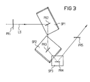
- FIG. 3 shows a possible construction of a rotating device D shown.
- the laser beam LS comes with a Polarization direction PR1 on and is on a first mirror SP1 steered. This is, for example, with an x-y-z spatial coordinate -45 °, -45 °, 0 ° set.
- the first mirror Spl rotates the polarization direction PR1 in the polarization direction PR2.
- the laser beam LS is from the first mirror SP1 to a second mirror SP2, for example the spatial coordinates 0 °, 45 °, -45 °.
- the second mirror SP2 rotates the direction of polarization PR2 in the direction of polarization PR3.
- the laser beam LS is from the second mirror SP2 to a third mirror SP3, for example the spatial coordinates -90 °, a °, 0 °.
- the third mirror SP3 rotates the polarization direction PR3 in a polarization direction PR4, which is simultaneously the radiation polarization direction PR5 corresponds with that of the laser beam LS on the polygon mirror P is steered.
- The is advantageously difference between the polarization directions PR1 and PR5 90 degrees.
- GBPF is not exclusive to understand a relatively large area. This can occur in individual cases also have small dimensions.
Abstract
Description
Die Erfindung betrifft Verfahren zur dreidimensionalen Bilddarstellung auf einer Großbildprojektionsfläche mittels eines Laser-Projektors gemäß den Oberbegriffen der Ansprüche 1 und 3.The invention relates to methods for three-dimensional image display on a large screen projection surface using a Laser projector according to the preambles of claims 1 and 3rd
Es gibt verschiedene Ausführungen von Fernseh-Projektoren, die ein Bild auf eine Großbildprojektionsfläche projizieren können. Eine davon befaßt sich mit Laser-Projektoren. Ein Laser-Projektor ist zur zweidimensionalen Darstellung von Grafiken u.s.w. verwendbar. Bei einem Farb-Laser-Projektor beispielsweise wird Licht der Farben Rot, Grün und Blau durch drei Laser erzeugt. Die Lichtstrahlen werden durch einen sich drehenden Polygonspiegel horizontal abgelenkt. Die horizontale Ablenkung erlaubt die Darstellung einer Bildschirmzeile. Nach der horizontalen Ablenkung erfolgt durch einen weiteren sich drehenden Spiegel eine vertikale Ablenkung. Auf diese Weise wird über eine Optik das Bild auf eine Großbildprojektionsfläche projiziert. Ein Laser-Projektor ermöglicht somit die Darstellung von sehr großen Bildern mit besonders brillanten Farben.There are different types of television projectors, that project an image onto a large-screen projection surface can. One of them deals with laser projectors. A laser projector is for two-dimensional representation of graphics etc. usable. For example, with a color laser projector is light of the colors red, green and blue generated three lasers. The rays of light become through you rotating polygon mirror deflected horizontally. The horizontal Distraction allows the display of a screen line. After the horizontal distraction is followed by another rotating mirror a vertical distraction. To this The image is displayed on a large-screen projection surface using optics projected. A laser projector thus enables the display of very large images with particularly brilliant ones Colours.
Ein Farb-Laser-Projektor weist zwar drei Laser für die Farben Rot, Grün und Blau auf, das Laserprinzip ist aber bei allen drei Farben gleich. Es werden lediglich für einen einzelnen Bildpunkt auf der Großbildprojektionsfläche die verschiedenen Farben für eine entsprechend benötigte Gesamtfarbe einander überlagert.A color laser projector has three lasers for the colors Red, green and blue on, but the laser principle is common to everyone three colors the same. It will only be for an individual The different pixels on the large-screen projection surface Colors for a corresponding overall color required overlaid.
Unter den Laser-Projektoren gibt es zwei verschiedene Grundtypen. Die einen arbeiten mit Multimode- und die anderen mit Monomode-Lasern. Die von Monomode-Lasern erzeugten Laserstrahlen weisen eine einzige Polarisationsrichtung auf. Sie haben ein linear polarisiertes Licht. Demgegenüber haben die von Multimode-Lasern erzeugten Laserstrahlen zirkular polarisiertes Licht, d.h. sie haben mehr als nur eine Polarisationsrichtung. Beispielsweise haben sie 2, 4 u.s.w. verschiedene Polarisationsrichtungen. Im Extremfall streuen ihre Polarisationen nach allen Richtungen.There are two different basic types of laser projectors. Some work with multimode and others with Single mode lasers. The laser beams generated by single-mode lasers have a single polarization direction. she have a linearly polarized light. In contrast, they have Circularly polarized laser beams generated by multimode lasers Light, i.e. they have more than one direction of polarization. For example, they have 2, 4, etc. various Directions of polarization. In extreme cases, their polarizations scatter in all directions.
Das Prinzip der Laser-Display-Technik ist in der deutschen Zeitschrift Funkschau, 1995, Heft 18, Seiten 104 bis 107, unter der Spalte Technik und dem Titel "Die Laser-Display-Technik" und in einem auf der CeBIT 1995 herausgegebenen Verkaufsprospekt der Fa. Laser Display Technologie GmbH & Co. KG, Carl-Zeiss-Str. 2, 07552 Gera beschrieben. Ferner ist aus der deutschen Offenlegungsschrift DE 32 14 327 A1 bekannt, einen Bildschirm im zeilenweisen Wechsel mit Polarisationsfolien-Streifen abwechselnder Polarisationsrichtungen zu belegen, so daß sich je Fernsehhalbbild ein Stereohalbbild wiedergeben läßt.The principle of laser display technology is in German Funkschau magazine, 1995, issue 18, pages 104 to 107, at the Technology column and the title "The Laser Display Technology" and in a prospectus published at CeBIT 1995 from Laser Display Technologie GmbH & Co. KG, Carl-Zeiss-Str. 2, 07552 Gera. Furthermore is off known from German patent application DE 32 14 327 A1, a screen alternating with lines of polarizing film to show alternating directions of polarization, so that a stereo field is reproduced for each television field leaves.
Aus den Druckschriften EP-A-0 211 596 und JP-A-59/176 720 sind Verfahren für Großbildprojektoren bekannt, mit denen dreidimensionale Bilder dargestellt werden können. Dabei werden Polygonspiegel verwendet, auf deren Spiegelteile ein Laserstrahl frontal auftrifft.From documents EP-A-0 211 596 and JP-A-59/176 720 are known methods for large screen projectors with which three-dimensional images can be displayed. In doing so Polygon mirror used, on the mirror parts of a laser beam hits frontally.
Aus der Druckschrift DE-A-41 25 241 ist ebenfalls ein Verfahren für Großbildprojektoren bekannt, mit dem dreidimensionale Bilder darstellbar sind. Bei diesem Verfahren ist ein Polygonspiegel nicht verwendet.From the document DE-A-41 25 241 is also a method known for large-screen projectors, with the three-dimensional Images can be displayed. In this process is a polygon mirror not used.
Aufgabe der Erfindung ist es, Verfahren zur dreidimensionalen Bilddarstellung auf einer Großbildprojektionsfläche mittels des Funktionsprinzips eines Laser-Projektors anzugeben. The object of the invention is to provide methods for three-dimensional Image display on a large-screen projection surface using the principle of operation of a laser projector.
Diese Aufgabe wird durch Verfahren der eingangs genannten Art erfindungsgemäß mit den im Kennzeichen der Ansprüche 1 und 3 stehenden Verfahrensschritten gelöst.This task is accomplished by procedures of the type mentioned at the beginning According to the invention with those in the characterizing part of claims 1 and 3 standing procedural steps solved.
Danach wird unter der Anwendung des Multimode-Laser-Prinzips der Multimode-Laserstrahl auf in zwei unterschiedliche Richtungen jeweils abwechselnd lichtpolarisierende Spiegelteile des Polygonspiegels geworfen. Von den Spiegelteilen des Polygonspiegels aus werden entsprechend der jeweils abwechselnden lichtpolarisierenden Spiegelteile auf der Großbildprojektionsfläche jeweils abwechselnd Zeilen mit der einen und Zeilen mit der anderen Polarisationsrichtung geschrieben. Außerdem wird die Steuerung des Multimode-Laserstrahls in der Weise ausgeführt, daß auf der Großbildprojektionsfläche jeweils ein erstes Bild nur mit den Zeilen der einen Polarisationsrichtung und ein zweites Bild nur mit den Zeilen der anderen Polarisationsrichtung entsteht. Die jeweils beiden Bilder haben dabei die Eigenschaft, daß sie von einem Betrachter mit einer Brille mit einem ersten Brillenglas für die eine und mit einem zweiten Brillenglas für die andere Polarisationsrichtung zu einem dreidimensionalen Gesamtbild zusammenfaßbar sindAfter that, using the multimode laser principle the multimode laser beam is directed in two different directions each alternating light-polarizing mirror parts thrown of the polygon mirror. From the mirror parts of the polygon mirror are made according to the alternating light-polarizing mirror parts on the large-screen projection surface alternately lines with one and lines written with the other direction of polarization. Moreover is controlling the multimode laser beam in the way executed that in each case on the large-screen projection surface first picture only with the lines of one polarization direction and a second image only with the lines of the other polarization direction arises. Both have two pictures the property of being viewed by a viewer with a Glasses with a first lens for one and with one second lens for the other direction of polarization can be summarized in a three-dimensional overall picture
Unter Anwendung des Monomode-Laserprinzips wird der Monomode-Laserstrahl vor dem Auftreffen aus einer ersten Richtung auf jeweilige zugehörige erste Spiegelteile des Polygonspiegels, die für eine Ablenkung auf jeweils erste Zeilen von jeweils aufeinanderfolgenden ersten und zweiten Zeilen der Großbildprojektionsfläche sorgen, durch einen teiltransparenten Spiegel gelenkt. Der teiltransparente Spiegel dient zum Ablenken eines Teilstrahls des Monomode-Laserstrahls. Nach dem teiltransparenten Spiegel bzw. nach dem Ablenken eines Teilstrahles des Monomode-Laserstrahls wird wahlweise entweder der abgelenkte Teilstrahl oder der nicht abgelenkte Monomode-Laserstrahl in seiner Polarisationsrichtung gedreht. Der abgelenkte und gegebenenfalls gedrehte Teilstrahl wird aus einer gegenüber der ersten Richtung zweiten Richtung auf jeweilige zugehörige zweite Spiegelteile des Polygonspiegels für eine Ablenkung auf die jeweils zweiten Zeilen der jeweils aufeinanderfolgenden ersten und zweiten Zeilen der Großbildprojektionsfläche gelenkt. Die Steuerung des Monomode-Laserstrahls erfolgt dabei in der Weise, daß auf der Großbildprojektionsfläche jeweils ein erstes Bild mit der gedrehten/ungedrehten Polarisationsrichtung auf den jeweils ersten Zeilen und ein zweites Bild mit der ungedrehten/gedrehten Polarisationsrichtung auf den jeweils zweiten Zeilen der Großbildprojektionsfläche entsteht. Die jeweils erzeugten beiden Bilder haben dabei die Eigenschaft, daß sie von einem Betrachter mit einer Brille mit einem ersten Brillenglas für die eine und mit einem zweiten Brillenglas für die andere Polarisationsrichtung zu einem dreidimensionalen Gesamtbild zusammenfaßbar sind. Using the single mode laser principle, the single mode laser beam before hitting from a first direction respective associated first mirror parts of the polygon mirror, those for a distraction to first rows of each successive first and second lines of the large-screen projection surface care through a partially transparent mirror directed. The partially transparent mirror serves as a distraction of a partial beam of the single-mode laser beam. After the partially transparent Mirror or after deflecting a partial beam of the single-mode laser beam is either the deflected one Partial beam or the undeflected single-mode laser beam rotated in its polarization direction. The distracted and possibly rotated partial beam is made from a opposite the first direction second direction to respective associated second mirror parts of the polygon mirror for a distraction to the second lines of each successive first and second lines of the large-screen projection surface directed. The control of the single-mode laser beam takes place in such a way that on the large screen projection surface always a first picture with the rotated / unrotated Direction of polarization on the first Lines and a second image with the unrotated / rotated polarization direction on the second lines of the large screen projection area arises. The two generated each Pictures have the property that they are from a viewer with glasses with a first lens for one and with a second lens for the other polarization direction can be summarized in a three-dimensional overall picture are.
Beide Verfahren ermöglichen somit einem Betrachter das dreidimensionale sehen auf einer Großbildprojektionsfläche mittels des Funktionsprinzips eines Laser-Projektors.Both methods thus enable the viewer to see the three-dimensional one see on a large-screen projection surface using the principle of operation of a laser projector.
Vorteilhafte Ausgestaltungen der Erfindung sind Gegenstand von Unteransprüchen. Danach ist bei Verwendung von zwei unterschiedlichen Polarisationsrichtungen, die zueinander um 90 Grad gedreht sind, eine maximale Übersprechdämpfung zwischen den jeweils dargestellten beiden Bildern mit unterschiedlichen Polarisationsrichtungen gegeben.Advantageous embodiments of the invention are the subject of subclaims. After that, when using two different ones Polarization directions that are 90 to each other Degrees are rotated, maximum crosstalk attenuation between the two images shown with different Given directions of polarization.
Weist der teiltransparente Spiegel eine Transparenz von 50% auf, haben der nach dem teiltransparenten Spiegel erhaltene und der abgelenkte Laserstrahl jeweils gleiche Energieleistungen. Eine Weiternutzung der beiden Teillaserstrahlen ist dadurch besonders einfach, da eine Anpassung der Energieleistungen aneinander entfällt.If the partially transparent mirror has a transparency of 50% on, have received after the partially transparent mirror and the deflected laser beam each have the same energy output. The two partial laser beams can still be used therefore particularly easy, since an adjustment of the energy performance to each other.
Zur Erzeugung der beiden Bilder wird die Großbildprojektionsfläche Zeile für Zeile abgetastet. Beim Momomode-Laserprinzip wird für das Schreiben der jeweils ersten Zeilen der Laserstrahl aus der einen Richtung und für das Schreiben der jeweils zweiten Zeilen der Laserstrahl aus der anderen Richtung verwendet. Wird beim Schreiben der jeweils einen Zeilen der Laserstrahl zum Schreiben für die jeweils anderen Zeilen auf eine Absorbtionsfläche gelenkt, wird ein zugehöriges Gerät innenseitig nicht beleuchtet und erwärmt. Wird der Laserstrahl auf eine Photovoltaikplatte gelenkt, kann zu einem gewissen Grad Energie aus dem Laserstrahl zurückgewonnen werden.The large-screen projection surface is used to generate the two images Scanned line by line. With the momomode laser principle is used to write the first lines of the laser beam from one direction and for writing each second lines of laser beam from the other direction used. When writing one line at a time, the Laser beam for writing on the other lines directed an absorption surface becomes an associated device not illuminated and heated on the inside. Will the laser beam Steered onto a photovoltaic panel can lead to some Degrees of energy can be recovered from the laser beam.
Nachfolgend werden zwei Ausführungsbeispiele der Erfindung anhand einer Zeichnung näher erläutert. Darin zeigen
- Figur 1
- ein Prinzipschaltbild eines erfindungsgemäßen Multimode-Laser-Projektors
- Figur 2
- ein Prinzipschaltbild eines erfindungsgemäßen Mono-mode-Laser-Projektors, und
- Figur 3
- eine Dreheinrichtung aus der Figur 2 in Prinzipdarstsellung zum Drehen der Polarisationsrichtung des abgelenkten Laser-Teilstrahls.
- Figure 1
- a schematic diagram of a multimode laser projector according to the invention
- Figure 2
- a schematic diagram of a mono-mode laser projector according to the invention, and
- Figure 3
- a rotating device from Figure 2 in principle for rotating the direction of polarization of the deflected laser beam.
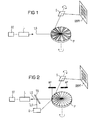
In den Figuren 1 und 2 sind nur jeweils ein Laser L dargestellt. Bei Farbprojektoren sind Laser L für jeweils eine der Farben Rot, Grün und Blau vorgesehen. Jeder dieser Laser L arbeitet aber nach dem gezeigten Prinzip, so daß an dieser Stelle nur jeweils ein Laser L gezeigt werden muß.Only one laser L is shown in each of FIGS. 1 and 2. In color projectors, lasers L are one for each Colors red, green and blue provided. Each of these lasers L but works on the principle shown, so that on this Place only one laser L must be shown at a time.
In den Figuren 1 und 2 sind die für das Verständnis der Erfindung notwendigen grundlegenden Teile eines Laser-Projektors dargestellt. Es sind einmal ein bereits angesprochener Laser L, der einen Laserstrahl LS abgibt, ein Polygonspiegel P, der für eine horizontale Laserstrahl-Ablenkung zuständig ist, ein weiterer Spiegel S, der für eine vertikale Laserstrahl-Ablenkung zuständig ist, und eine Steuerung ST für die Steuerung des vom Laser L abgegebenen Laserstrahls LS.Figures 1 and 2 are for understanding the invention necessary basic parts of a laser projector shown. There is one already mentioned Laser L, which emits a laser beam LS, a polygon mirror P, who is responsible for horizontal laser beam deflection is, another mirror S, which is used for vertical laser beam deflection is responsible, and a controller ST for the Control of the laser beam LS emitted by the laser L.
Der für die horizontale Ablenkung des Laserstrahls LS zuständige Polygonspiegel P rotiert um eine Achse. Die Rotatation ist durch einen entsprechenden Pfeil um die betreffende Achse angedeutet. Der weitere Spiegel S schwenkt im Ausführungsbeispiel hin und her, ebenfalls angedeutet durch einen entsprechenden Pfeil um die entsprechende Achse.The person responsible for the horizontal deflection of the laser beam LS Polygon mirror P rotates around an axis. The rotation is by a corresponding arrow around the relevant axis indicated. The further mirror S pivots in the exemplary embodiment back and forth, also indicated by a corresponding one Arrow around the corresponding axis.
In der Figur 1 handelt es sich bei dem Laser L um einen Multimode-Laser, während es sich beim dem Laser L in der Figur 2 um einen Monomode-Laser handelt.In FIG. 1, the laser L is a multimode laser, while the laser L in FIG. 2 is a single-mode laser.
Das Grundprinzip eines Laserprojektors ist, daß der vom Laser L erzeugte Laserstrahl LS auf den Polygonspiegel P geworfen wird. Der Polygonspiegel P besteht dabei aus vielen, z.B. 32 Spiegelteilen, die jeweils für eine Zeile einer Großbildprojektionsfläche GBPF zuständig sind. Die Spiegelteile sind vom Umfangverlauf gesehen sägezahnförmig angeordnet. Dies kommt daher, weil die Spiegelteile wie die Blätter einer Luftschraube angeordnet sind und jeweils einen Anstellwinkel aufweisen. Der Laserstrahl LS trifft jeweils auf einen Spiegelteil von der Seite. Durch die Drehung des Polygonspiegels P und dem jeweiligen schräggestellten Spiegelteil erfährt der Laserstrahl LS neben einer Strahlablenkung eine lineare Strahlbewegung im abgelenkten Strahlteil. Durch Umlenken des linear bewegten Strahlteils des Laserstrahls LS durch den weiteren Spiegel S auf die Großbildprojektionsfläche GBPF kann auf diese Weise eine Zeile der Großbildprojektionsfläche GBPF beschrieben werden.The basic principle of a laser projector is that of a laser L generated laser beam LS thrown onto the polygon mirror P. becomes. The polygon mirror P consists of many, e.g. 32 Mirror parts, each for one line of a large-screen projection surface GBPF are responsible. The mirror parts are from Circumferential course seen sawtooth-shaped. This is coming therefore, because the mirror parts like the blades of an airscrew are arranged and each have an angle of attack. The laser beam LS hits a mirror part in each case of the page. By rotating the polygon mirror P and the respective inclined mirror part of the Laser beam LS next to a beam deflection a linear one Beam movement in the deflected part of the beam. By redirecting the linearly moving beam part of the laser beam LS through the another mirror S onto the large-screen projection surface GBPF can thus line up the large-screen projection surface GBPF can be described.
Wird bei einem Wechsel des auf den Polygonspiegel P treffenden Laserstrahls LS auf einen nächsten Spiegelteil der weitere Spiegel S um einen Anteil weitergedreht, kann mit dem nächsten Spiegelteil eine nächste Zeile auf der Großbildprojektionsfläche GBPF beschrieben werden. Nach Durchlauf aller Spiegelteile wird der weitere Spiegel S zurückgestellt, und die Abtastung der Großbildprojektionsfläche GBPF kann von vorne beginnen. Insgesamt wird auf diese Weise ein zweidimensionales Bild dargestellt.Is when changing the one that meets the polygon mirror P. Laser beam LS on a next mirror part the other Mirror S rotated further by a portion, can with the next mirror part a next line on the large screen projection surface GBPF can be described. After all Mirror parts, the further mirror S is reset, and the scan of the large screen projection area GBPF can be from start at the beginning. Overall, this becomes a two-dimensional one Image shown.
Zur Darstellung eines dreidimensionales Bild wird gemäß der Figur 1, der Laserstrahl LS auf einen Polygonspiegel P geworfen, dessen Spiegelteile in zwei Polarisationsrichtungen abwechselnd lichtpolarisierende Schichten aufweist. In der Figur 1 ist dies durch abwechselnd schraffierte und nicht schraffierte Flächen dargestellt. Da der Laserstrahl LS ein Multimode-Laserstrahl ist, kann dieser direkt auf den Polygonspiegel P gelenkt werden. Von dem Multimode-Laserstrahl werden jeweils die Polarisationsrichtungen durch den Polygonspiegel P herausgefiltert, die den Polarisationsrichtungen der polarisierenden Schichten der Spiegelflächen entsprechen. To display a three-dimensional image, according to the FIG. 1, the laser beam LS thrown onto a polygon mirror P, whose mirror parts alternate in two polarization directions has light-polarizing layers. In the figure 1 this is by alternately hatched and not hatched areas. Since the laser beam LS Is multimode laser beam, this can be directly on the polygon mirror P be directed. From the multimode laser beam are the polarization directions through the polygon mirror P filtered out the polarization directions correspond to the polarizing layers of the mirror surfaces.
Günstigerweise wird von Anfang an ein Multimode-Laser verwendet, der nur diese beiden Polarisationsrichtungen aufweist, weil dann durch geringste Energieverluste eine optimale Energiebilanz erreicht wird. A multimode laser is favorably used right from the start, which has only these two polarization directions, because then an optimal energy balance through minimal energy losses is achieved.
Durch den beschichteten Polygonspiegel P werden jeweils erste Zeilen von jeweils aufeinanderfolgenden ersten und zweiten Zeilen der Großbildprojektionsfläche GBPF mit der einen Polarisationsrichtung und die jeweils zweiten Zeilen mit der anderen Polarisationsrichtung beschrieben. In der Figur 1 ist dies durch dicker und dünner dargestellte Zeilen verdeutlicht.The coated polygon mirror P makes the first Lines of consecutive first and second Lines of the large-screen projection area GBPF with one polarization direction and the second lines with the other Direction of polarization described. In Figure 1 is this is illustrated by thicker and thinner lines.
Erfolgt über die Steuerung ST eine Steuerung des Laserstrahls LS derart, daß auf der Großbildprojektionsfläche GBPF jeweils ein erstes Bild nur mit den Zeilen der einen Polarisationsrichtung und ein zweites Bild nur mit den Zeilen der anderen Polarisationsrichtung entsteht, wobei solche Bilder erzeugt werden sollen, daß von einem Betrachter mit einer Brille mit einem ersten Brillenglas für die eine und mit einem zweiten Brillenglas für die andere Polarisationsrichtung die Bilder vom Inhalt her zu einem sinnvollen dreidimensionalen Gesamtbild zusammenfaßbar sind, kann mit dem vorliegenden Laser-Projektor eine dreidimensionale Bilddarstellung realisiert werden.Control of the laser beam takes place via the control ST LS such that on the large-screen projection surface GBPF each a first picture only with the lines of one polarization direction and a second picture only with the lines of the other The direction of polarization arises, producing such images should be that of a viewer with glasses a first lens for one and with a second Glasses for the other polarization direction the pictures from the content to a meaningful three-dimensional overall picture can be summarized with the present laser projector realized a three-dimensional image become.
Handelt es sich beim dem Laser L um einen Monomode-Laser, kann das Prinzip nach Figur 1 nicht angewendet werden, weil der Laserstrahl LS durch die unterschiedlich polarisierenden Beschichtungen der Spiegelteile des Polygonspiegel P einmal weitergeleitet wird, das andere mal aber wegen nicht zusammenpassender Polarisationsrichtung zwischen dem Laserstrahl LS und der Beschichtung absorbiert wird. In diesem Fall wird gemäß der Figur 2 der Laserstrahl LS durch einen teiltransparenten Spiegel TS gelenkt, bevor er auf den Polygonspiegel P gelenkt wird. Der Polygonspiegel P benötigt dabei keinerlei lichtpolarisierende Schicht. Bei den Spiegelteilen handelt es sich um einfache Spiegel.If the laser L is a single-mode laser, the principle of Figure 1 cannot be applied because the laser beam LS due to the different polarizing Coatings of the mirror parts of the polygon mirror P once is forwarded, the other time because of mismatching Direction of polarization between the laser beam LS and the coating is absorbed. In this case according to FIG. 2, the laser beam LS through a partially transparent one Mirror TS steered before it on the polygon mirror P is directed. The polygon mirror P does not need any light polarizing layer. The mirror parts are simple mirrors.
Der teiltransparente Spiegel TS lenkt einen Teilstrahl TSL ab. Vorteilhafterweise weist der teiltransparente Spiegel TS eine Transparenz von 50% auf, so daß der Teilstrahl TSL und der noch durch den teiltransparente Spiegel TS hindurchgehende Laserstrahl jeweils einen Energieanteil von 50% haben.The partially transparent mirror TS guides a partial beam TSL from. The partially transparent mirror advantageously has TS a transparency of 50%, so that the partial beam TSL and the one that still passes through the partially transparent mirror TS Laser beam each have an energy share of 50%.
Der Teilstrahl TSL wird in eine Dreheinrichtung D gelenkt. In der Dreheinrichtung D wird die Polarisationsrichtung des Teilstrahls TSL vorzugsweise um 90 Grad gedreht. Aus der Dreheinrichtung D wird der Teilstrahl TSL dann auf den Polygonspiegel P aus einer anderen Richtung als der ungedrehte Laserstrahl nach dem teiltransparenten Spiegel TS gelenkt. Bei entsprechenden Anstellungen der zum gedrehten bzw. nicht gedrehten Laserstrahlen gehörenden Spiegelteile des Polygonspiegels P können damit auf der Großbildprojektionsfläche GBPF in entsprechender Weise wie bei der Figur 1 jeweils erste Zeilen mit der einen Polarisationsrichtung und jeweils zweite Zeilen mit der anderen Polarisationsrichtung beschrieben werden. Letztlich können damit wieder jeweils zwei Bilder mit unterschiedlichen Polarisationsrichtungen erzeugt werden, die von einem Betrachter mit einer entsprechenden, oben bereits angesprochenen Brille zu einem dreidimensionalen Bild zusammenfaßbar sind.The partial beam TSL is directed into a rotating device D. In the rotating device D becomes the polarization direction of the Partial beam TSL preferably rotated by 90 degrees. From the rotating device D the partial beam TSL is then on the polygon mirror P from a different direction than the unrotated laser beam directed to the semi-transparent mirror TS. At corresponding positions of the rotated or not rotated Mirror parts of the polygon mirror belonging to laser beams P can thus on the large screen projection surface GBPF in the same way as in FIG. 1 in each case first Lines with one direction of polarization and each second lines with the other direction of polarization become. Ultimately, you can use two pictures each are generated with different polarization directions, that of a viewer with a corresponding one already above addressed glasses to a three-dimensional image can be summarized.
Durch die Anpassung der Anstellungen der abwechselnd eingestellten Spiegelteile des Polygonspiegel P an die Richtungen, aus denen der jeweils zugehörige Laserstrahl kommt, ergibt sich der Vorteil, daß der jeweils andere Laserstrahl für die jeweils anders eingestellten Spiegelteile des Polygonspiegels P vom weiteren Spiegel S weggelenkt wird, so daß dieser unwirksam bleibt. Vorteilhafterweise wird dieser unwirksame bzw. gerade nicht benötigte Laserstrahl auf eine Absorbtions- oder Photovoltaikplatte AP gelenkt.By adjusting the settings of the alternately set Mirror parts of the polygon mirror P to the directions, from which the associated laser beam comes the advantage that the other laser beam for the each differently set mirror parts of the polygon mirror P is directed away from the further mirror S, so that it is ineffective remains. This is advantageously ineffective or a laser beam that is not currently needed on an absorption or AP photovoltaic panel.
In der Figur 3 ist ein möglicher Aufbau einer Dreheinrichtung D gezeigt. Eingangsseitig kommt der Laserstrahl LS mit einer Polarisationsrichtung PR1 an und wird auf einen ersten Spiegel SP1 gelenkt. Dieser ist beispielsweise mit einer x-y-z-Raumkoordinate -45°, -45°, 0° eingestellt. Der erste Spiegel Spl dreht die Polarisationsrichtung PR1 in die Polarisationsrichtung PR2. Vom ersten Spiegel SP1 wird der Laserstrahls LS zu einem zweiten Spiegel SP2, der beispielsweise die Raumkoordinaten 0°, 45°, -45° hat, gelenkt. Der zweite Spiegel SP2 verdreht die Polarisationsrichtung PR2 in die Polarisationsrichtung PR3. Vom zweiten Spiegel SP2 wird der Laserstrahl LS auf einen dritten Spiegel SP3, der beispielsweise die Raumkoordinaten -90°, a°, 0° hat, gelenkt. Der dritte Spiegel SP3 dreht die Polarisationsrichtung PR3 in eine Polarisationsrichtung PR4, die gleichzeitig der Abstrahlpolarisationsrichtung PR5 entspricht, mit der der Laserstrahls LS auf den Polygonspiegel P gelenkt wird. Vorteilhafterweise beträgt der unterschied der Polarisationsrichtungen PR1 und PR5 90 Grad.FIG. 3 shows a possible construction of a rotating device D shown. On the input side, the laser beam LS comes with a Polarization direction PR1 on and is on a first mirror SP1 steered. This is, for example, with an x-y-z spatial coordinate -45 °, -45 °, 0 ° set. The first mirror Spl rotates the polarization direction PR1 in the polarization direction PR2. The laser beam LS is from the first mirror SP1 to a second mirror SP2, for example the spatial coordinates 0 °, 45 °, -45 °. The second mirror SP2 rotates the direction of polarization PR2 in the direction of polarization PR3. The laser beam LS is from the second mirror SP2 to a third mirror SP3, for example the spatial coordinates -90 °, a °, 0 °. The third mirror SP3 rotates the polarization direction PR3 in a polarization direction PR4, which is simultaneously the radiation polarization direction PR5 corresponds with that of the laser beam LS on the polygon mirror P is steered. The is advantageously difference between the polarization directions PR1 and PR5 90 degrees.
Unter Großbildprojektionsfläche GBPF ist nicht ausschließlich eine relativ große Fläche zu verstehen. Diese kann im Einzelfall auch kleine Ausmaße haben.Under large screen projection area GBPF is not exclusive to understand a relatively large area. This can occur in individual cases also have small dimensions.
Claims (6)
- Method for three-dimensional imaging on a large-area projection surface (GBPF) by means of the functional principle of a laser projector having a rotating polygonal mirror (P) for line deflection, having at least one laser (L) outputting a multimode laser beam (LS), characterized in that the multimode laser beam (LS) is cast from the side onto mirror parts of the polygonal mirror (P) which respectively polarize light alternately in two different directions, and are arranged like the blades of an air screw and respectively have a setting angle and starting from which, in accordance with respectively alternating light-polarizing mirror parts set at the angle, respectively alternating lines of one direction of polarization and lines of the other direction of polarization are written on the large-area projection surface (GBPF), and in that the control of the multimode laser beam (LS) is carried out in such a way that a first image having only the lines of one direction of polarization and a second image having only the lines of the other direction of polarization are respectively produced on the large-area projection surface (GBPF) with the respective property that they can be combined to form a three-dimensional overall image by a viewer having spectacles with a first spectacle lens for one direction of polarization and with a second spectacle lens for the other direction of polarization.
- Method according to Claim 1, characterized in that the images respectively produced with two different directions of polarization are produced with directions of polarization differing by 90 degrees.
- Method for three-dimensional imaging on a large-area projection surface (GBPF) by means of the functional principle of a laser projector having a rotating polygonal mirror (P) for a line deflection, having at least one laser (L) outputting a multimode laser beam (LS), characterized in that, before impinging from a first direction on respective associated first mirror parts of the polygonal mirror (P) for deflection respectively onto first lines of respectively successive first and second lines of the large-area projection surface (GBPF), the monomode laser beam (LS) is directed by a semi-transparent mirror (TS) for deflecting a partial beam (TSL), in that optionally either the deflected partial beam (TSL) or the non-deflected monomode laser beam (LS) is rotated downstream of the semi-transparent mirror (TS) in its direction of polarization, in that the deflected and, if appropriate, rotated partial beam (TSL) is directed from a second direction by comparison with the first direction onto respective associated second mirror parts of the polygonal mirror (P) for deflection onto the respectively second lines of the respectively successive first and second lines of the large-area projection surface (GBPF), and in that the control of the monomode laser beam (LS) is carried out in such a way that a first image having the rotated/non-rotated direction of polarization on the respectively first lines and a second image having the non-rotated/rotated direction of polarization on the respectively second lines of the large-area projection surface (GBPF) are respectively produced on the large-area projection surface (GBPF), with the respective property that they can be combined to form a three-dimensional overall image by a viewer having spectacles with a first spectacle lens for one direction of polarization and with a second spectacle lens for the other direction of polarization.
- Method according to Claim 3, characterized in that the monomode laser beam (LS) is directed through a semi-transparent mirror (TS) having a 50% transparency.
- Method according to Claim 3 or 4, characterized in that the rotation of a laser beam (LS) is carried out through 90 degrees by mirrors.
- Method according to one of Claims 3 to 5, characterized in that the laser beam (LS) not associated with respective mirror parts of the polygonal mirror (P) is directed onto an absorption surface or a photovoltaic plate (AP).
Applications Claiming Priority (3)
| Application Number | Priority Date | Filing Date | Title |
|---|---|---|---|
| DE19626096 | 1996-06-28 | ||
| DE19626096A DE19626096C1 (en) | 1996-06-28 | 1996-06-28 | Three dimensional image representation method using laser projector |
| PCT/DE1997/001286 WO1998000748A1 (en) | 1996-06-28 | 1997-06-19 | Method of three-dimensional imaging on a large-screen projection surface using a laser projector |
Publications (2)
| Publication Number | Publication Date |
|---|---|
| EP0907902A1 EP0907902A1 (en) | 1999-04-14 |
| EP0907902B1 true EP0907902B1 (en) | 2000-08-30 |
Family
ID=7798372
Family Applications (1)
| Application Number | Title | Priority Date | Filing Date |
|---|---|---|---|
| EP97931632A Expired - Lifetime EP0907902B1 (en) | 1996-06-28 | 1997-06-19 | Method of three-dimensional imaging on a large-screen projection surface using a laser projector |
Country Status (7)
| Country | Link |
|---|---|
| US (1) | US6109750A (en) |
| EP (1) | EP0907902B1 (en) |
| JP (1) | JP2000514201A (en) |
| AT (1) | ATE196016T1 (en) |
| DE (2) | DE19626096C1 (en) |
| ES (1) | ES2151738T3 (en) |
| WO (1) | WO1998000748A1 (en) |
Families Citing this family (16)
| Publication number | Priority date | Publication date | Assignee | Title |
|---|---|---|---|---|
| GB9811695D0 (en) * | 1998-06-01 | 1998-07-29 | Tricorder Technology Plc | Facial image processing method and apparatus |
| US6719719B2 (en) | 1998-11-13 | 2004-04-13 | Elan Pharma International Limited | Spike for liquid transfer device, liquid transfer device including spike, and method of transferring liquids using the same |
| JP5074652B2 (en) | 2000-02-08 | 2012-11-14 | ライスユニバーシティ | Optically active nanoparticles used in therapeutic and diagnostic methods |
| AU2002241777A1 (en) * | 2000-11-03 | 2002-06-03 | Actuality Systems, Inc. | Three-dimensional display systems |
| KR20020073054A (en) * | 2001-03-14 | 2002-09-19 | 한국과학기술연구원 | A Multi-layered Image Display System and Methods |
| DE10135418B4 (en) * | 2001-07-20 | 2004-07-15 | Jenoptik Ldt Gmbh | Raster projection of an image with back and forth light beam guidance |
| GB2382881A (en) * | 2001-12-10 | 2003-06-11 | Wynne Willson Gottelier Ltd | Digital image projector with deflector array |
| US7184104B2 (en) * | 2002-05-03 | 2007-02-27 | Hewlett-Packard Development Company, L.P. | Projector having scanning optics |
| US20040109480A1 (en) * | 2002-12-06 | 2004-06-10 | Vandruff Dean | Atmosperic light beam projection apparatus and method |
| DE10332275B4 (en) * | 2003-07-10 | 2005-05-04 | Deutsches Zentrum für Luft- und Raumfahrt e.V. | Panoramic image projector |
| US20050093818A1 (en) * | 2003-11-05 | 2005-05-05 | Lightbay Networks Corporation | Dynamic laser projection display |
| US20080241262A1 (en) * | 2004-03-29 | 2008-10-02 | The University Of Houston System | Nanoshells and Discrete Polymer-Coated Nanoshells, Methods For Making and Using Same |
| JP2006047421A (en) * | 2004-07-30 | 2006-02-16 | Canon Inc | Display optical system and image projection apparatus |
| US20100231868A1 (en) * | 2009-03-13 | 2010-09-16 | Alvis Technologies Inc. | Display device |
| US20130176407A1 (en) * | 2012-01-05 | 2013-07-11 | Reald Inc. | Beam scanned display apparatus and method thereof |
| CN104297928B (en) * | 2013-07-15 | 2017-03-01 | 台达电子工业股份有限公司 | 3 d display device and its projecting method of application |
Family Cites Families (7)
| Publication number | Priority date | Publication date | Assignee | Title |
|---|---|---|---|---|
| DE3214327A1 (en) * | 1982-04-19 | 1983-10-20 | Alex H. Dr. 6761 Dörnbach Blin | Stereoscopic image reproduction by spatially separated representation of image information for the left and right eye on a display screen and different polarisation of the light intended for the left and right eye |
| JPS59176720A (en) * | 1983-03-26 | 1984-10-06 | Fuotoron:Kk | Stereoscopic projector |
| EP0211596A3 (en) * | 1985-08-07 | 1988-08-31 | STREET, Graham Stewart Brandon | Apparatus for the display of high definition images |
| JPH0281037A (en) * | 1988-09-17 | 1990-03-22 | Olympus Optical Co Ltd | Optical system of finder |
| DE4125241C2 (en) * | 1991-07-26 | 1998-08-06 | Michael Dipl Phys Sollinger | Laser projector |
| DE4324848C1 (en) * | 1993-07-23 | 1995-03-30 | Schneider Rundfunkwerke Ag | Video projection system |
| DE19537356C1 (en) * | 1995-10-06 | 1996-12-05 | Ldt Gmbh & Co | Method of producing stereoscopic video picture |
-
1996
- 1996-06-28 DE DE19626096A patent/DE19626096C1/en not_active Expired - Fee Related
-
1997
- 1997-06-19 JP JP10503730A patent/JP2000514201A/en active Pending
- 1997-06-19 AT AT97931632T patent/ATE196016T1/en not_active IP Right Cessation
- 1997-06-19 US US09/202,444 patent/US6109750A/en not_active Expired - Fee Related
- 1997-06-19 WO PCT/DE1997/001286 patent/WO1998000748A1/en active IP Right Grant
- 1997-06-19 EP EP97931632A patent/EP0907902B1/en not_active Expired - Lifetime
- 1997-06-19 DE DE59702290T patent/DE59702290D1/en not_active Expired - Fee Related
- 1997-06-19 ES ES97931632T patent/ES2151738T3/en not_active Expired - Lifetime
Also Published As
| Publication number | Publication date |
|---|---|
| WO1998000748A1 (en) | 1998-01-08 |
| EP0907902A1 (en) | 1999-04-14 |
| JP2000514201A (en) | 2000-10-24 |
| ES2151738T3 (en) | 2001-01-01 |
| DE19626096C1 (en) | 1997-06-19 |
| ATE196016T1 (en) | 2000-09-15 |
| US6109750A (en) | 2000-08-29 |
| DE59702290D1 (en) | 2000-10-05 |
Similar Documents
| Publication | Publication Date | Title |
|---|---|---|
| EP1016274B1 (en) | System in which light is directed from a light source onto a surface | |
| EP0907902B1 (en) | Method of three-dimensional imaging on a large-screen projection surface using a laser projector | |
| EP0909517B1 (en) | Method and facility for light-beam projection of images on a screen | |
| DE4324849C2 (en) | Video system for generating a color video image on a screen | |
| DE69433600T2 (en) | Projection display device | |
| EP2357831B1 (en) | Method and system for light-beam projection of images on a screen | |
| DE2331012A1 (en) | DEVICE FOR SENSING THE RADIANT ENERGY FROM A SCENE | |
| DE3441745A1 (en) | SPACE IMAGE VISOR | |
| DE102005058586B4 (en) | Reproduction device for autostereoscopic reproduction of three-dimensional representations | |
| EP1145069A2 (en) | Assembly, in which light from a light source is directed onto a surface | |
| DE1462404C3 (en) | Device for reproducing a multicolored television picture | |
| DE2645010A1 (en) | COLOR TELEVISION CAMERA | |
| DE888562C (en) | Device for the reproduction of television pictures | |
| DE19829518C2 (en) | Device for folding a beam path, optical system in a laser projection display system and laser projection display system with such an optical system | |
| DE19620658C1 (en) | Head-mounted display device | |
| DE4125241C2 (en) | Laser projector | |
| DE102008029789B4 (en) | projection system | |
| DE102008029788B4 (en) | projection system | |
| EP2225610B1 (en) | Method and device for projecting an image onto a projection surface | |
| EP3807694A1 (en) | Head-up display with exactly aligned optical waveguides | |
| DE10123933C1 (en) | Stereoscopic information representation method uses laser beam for scanning projection surface with structured pixel elements | |
| DE102008029785B4 (en) | projection system | |
| DE102008029787B4 (en) | projection system | |
| DE19907345A1 (en) | Raster image display device for computer screen, includes arrangement for centralizing image at output of projection optics | |
| WO2019238894A1 (en) | Apparatus for displaying an image |
Legal Events
| Date | Code | Title | Description |
|---|---|---|---|
| PUAI | Public reference made under article 153(3) epc to a published international application that has entered the european phase |
Free format text: ORIGINAL CODE: 0009012 |
|
| 17P | Request for examination filed |
Effective date: 19981217 |
|
| AK | Designated contracting states |
Kind code of ref document: A1 Designated state(s): AT BE CH DE ES FR GB IT LI NL SE |
|
| GRAG | Despatch of communication of intention to grant |
Free format text: ORIGINAL CODE: EPIDOS AGRA |
|
| GRAG | Despatch of communication of intention to grant |
Free format text: ORIGINAL CODE: EPIDOS AGRA |
|
| GRAH | Despatch of communication of intention to grant a patent |
Free format text: ORIGINAL CODE: EPIDOS IGRA |
|
| 17Q | First examination report despatched |
Effective date: 20000131 |
|
| GRAH | Despatch of communication of intention to grant a patent |
Free format text: ORIGINAL CODE: EPIDOS IGRA |
|
| GRAA | (expected) grant |
Free format text: ORIGINAL CODE: 0009210 |
|
| AK | Designated contracting states |
Kind code of ref document: B1 Designated state(s): AT BE CH DE ES FR GB IT LI NL SE |
|
| REF | Corresponds to: |
Ref document number: 196016 Country of ref document: AT Date of ref document: 20000915 Kind code of ref document: T |
|
| REG | Reference to a national code |
Ref country code: CH Ref legal event code: EP |
|
| REG | Reference to a national code |
Ref country code: CH Ref legal event code: PUE Owner name: SIEMENS NIXDORF INFORMATIONSSYSTEME AG TRANSFER- F |
|
| REF | Corresponds to: |
Ref document number: 59702290 Country of ref document: DE Date of ref document: 20001005 |
|
| REG | Reference to a national code |
Ref country code: CH Ref legal event code: NV Representative=s name: E. BLUM & CO. PATENTANWAELTE |
|
| RAP2 | Party data changed (patent owner data changed or rights of a patent transferred) |
Owner name: FUJITSU SIEMENS COMPUTERS GMBH |
|
| ITF | It: translation for a ep patent filed |
Owner name: STUDIO JAUMANN P. & C. S.N.C. |
|
| GBT | Gb: translation of ep patent filed (gb section 77(6)(a)/1977) |
Effective date: 20001107 |
|
| PG25 | Lapsed in a contracting state [announced via postgrant information from national office to epo] |
Ref country code: SE Free format text: LAPSE BECAUSE OF FAILURE TO SUBMIT A TRANSLATION OF THE DESCRIPTION OR TO PAY THE FEE WITHIN THE PRESCRIBED TIME-LIMIT Effective date: 20001130 |
|
| ET | Fr: translation filed | ||
| REG | Reference to a national code |
Ref country code: ES Ref legal event code: FG2A Ref document number: 2151738 Country of ref document: ES Kind code of ref document: T3 |
|
| NLT2 | Nl: modifications (of names), taken from the european patent patent bulletin |
Owner name: FUJITSU SIEMENS COMPUTERS GMBH |
|
| PLBE | No opposition filed within time limit |
Free format text: ORIGINAL CODE: 0009261 |
|
| STAA | Information on the status of an ep patent application or granted ep patent |
Free format text: STATUS: NO OPPOSITION FILED WITHIN TIME LIMIT |
|
| PG25 | Lapsed in a contracting state [announced via postgrant information from national office to epo] |
Ref country code: BE Free format text: LAPSE BECAUSE OF NON-PAYMENT OF DUE FEES Effective date: 20010630 |
|
| 26N | No opposition filed | ||
| BERE | Be: lapsed |
Owner name: SIEMENS NIXDORF INFORMATIONSSYSTEME A.G. Effective date: 20010630 |
|
| REG | Reference to a national code |
Ref country code: GB Ref legal event code: IF02 |
|
| PGFP | Annual fee paid to national office [announced via postgrant information from national office to epo] |
Ref country code: NL Payment date: 20040528 Year of fee payment: 8 |
|
| PGFP | Annual fee paid to national office [announced via postgrant information from national office to epo] |
Ref country code: AT Payment date: 20040603 Year of fee payment: 8 |
|
| PGFP | Annual fee paid to national office [announced via postgrant information from national office to epo] |
Ref country code: GB Payment date: 20040616 Year of fee payment: 8 |
|
| PGFP | Annual fee paid to national office [announced via postgrant information from national office to epo] |
Ref country code: FR Payment date: 20040618 Year of fee payment: 8 |
|
| PGFP | Annual fee paid to national office [announced via postgrant information from national office to epo] |
Ref country code: CH Payment date: 20040621 Year of fee payment: 8 |
|
| PGFP | Annual fee paid to national office [announced via postgrant information from national office to epo] |
Ref country code: ES Payment date: 20040708 Year of fee payment: 8 |
|
| PGFP | Annual fee paid to national office [announced via postgrant information from national office to epo] |
Ref country code: DE Payment date: 20040802 Year of fee payment: 8 |
|
| PG25 | Lapsed in a contracting state [announced via postgrant information from national office to epo] |
Ref country code: IT Free format text: LAPSE BECAUSE OF NON-PAYMENT OF DUE FEES;WARNING: LAPSES OF ITALIAN PATENTS WITH EFFECTIVE DATE BEFORE 2007 MAY HAVE OCCURRED AT ANY TIME BEFORE 2007. THE CORRECT EFFECTIVE DATE MAY BE DIFFERENT FROM THE ONE RECORDED. Effective date: 20050619 Ref country code: GB Free format text: LAPSE BECAUSE OF NON-PAYMENT OF DUE FEES Effective date: 20050619 Ref country code: AT Free format text: LAPSE BECAUSE OF NON-PAYMENT OF DUE FEES Effective date: 20050619 |
|
| PG25 | Lapsed in a contracting state [announced via postgrant information from national office to epo] |
Ref country code: ES Free format text: LAPSE BECAUSE OF NON-PAYMENT OF DUE FEES Effective date: 20050620 |
|
| PG25 | Lapsed in a contracting state [announced via postgrant information from national office to epo] |
Ref country code: LI Free format text: LAPSE BECAUSE OF NON-PAYMENT OF DUE FEES Effective date: 20050630 Ref country code: CH Free format text: LAPSE BECAUSE OF NON-PAYMENT OF DUE FEES Effective date: 20050630 |
|
| PG25 | Lapsed in a contracting state [announced via postgrant information from national office to epo] |
Ref country code: NL Free format text: LAPSE BECAUSE OF NON-PAYMENT OF DUE FEES Effective date: 20060101 |
|
| PG25 | Lapsed in a contracting state [announced via postgrant information from national office to epo] |
Ref country code: DE Free format text: LAPSE BECAUSE OF NON-PAYMENT OF DUE FEES Effective date: 20060103 |
|
| REG | Reference to a national code |
Ref country code: CH Ref legal event code: PL |
|
| PG25 | Lapsed in a contracting state [announced via postgrant information from national office to epo] |
Ref country code: FR Free format text: LAPSE BECAUSE OF NON-PAYMENT OF DUE FEES Effective date: 20060228 |
|
| GBPC | Gb: european patent ceased through non-payment of renewal fee |
Effective date: 20050619 |
|
| NLV4 | Nl: lapsed or anulled due to non-payment of the annual fee |
Effective date: 20060101 |
|
| REG | Reference to a national code |
Ref country code: FR Ref legal event code: ST Effective date: 20060228 |
|
| REG | Reference to a national code |
Ref country code: ES Ref legal event code: FD2A Effective date: 20050620 |