EP3553581A1 - Linsenstruktur, herstellungsverfahren dafür und kamera - Google Patents
Linsenstruktur, herstellungsverfahren dafür und kamera Download PDFInfo
- Publication number
- EP3553581A1 EP3553581A1 EP17889835.9A EP17889835A EP3553581A1 EP 3553581 A1 EP3553581 A1 EP 3553581A1 EP 17889835 A EP17889835 A EP 17889835A EP 3553581 A1 EP3553581 A1 EP 3553581A1
- Authority
- EP
- European Patent Office
- Prior art keywords
- lens
- light
- light shielding
- tube
- edge region
- Prior art date
- Legal status (The legal status is an assumption and is not a legal conclusion. Google has not performed a legal analysis and makes no representation as to the accuracy of the status listed.)
- Granted
Links
Images


Classifications
-
- G—PHYSICS
- G02—OPTICS
- G02B—OPTICAL ELEMENTS, SYSTEMS OR APPARATUS
- G02B7/00—Mountings, adjusting means, or light-tight connections, for optical elements
- G02B7/02—Mountings, adjusting means, or light-tight connections, for optical elements for lenses
- G02B7/025—Mountings, adjusting means, or light-tight connections, for optical elements for lenses using glue
-
- G—PHYSICS
- G02—OPTICS
- G02B—OPTICAL ELEMENTS, SYSTEMS OR APPARATUS
- G02B7/00—Mountings, adjusting means, or light-tight connections, for optical elements
- G02B7/02—Mountings, adjusting means, or light-tight connections, for optical elements for lenses
- G02B7/021—Mountings, adjusting means, or light-tight connections, for optical elements for lenses for more than one lens
-
- G—PHYSICS
- G02—OPTICS
- G02B—OPTICAL ELEMENTS, SYSTEMS OR APPARATUS
- G02B7/00—Mountings, adjusting means, or light-tight connections, for optical elements
- G02B7/02—Mountings, adjusting means, or light-tight connections, for optical elements for lenses
-
- G—PHYSICS
- G03—PHOTOGRAPHY; CINEMATOGRAPHY; ANALOGOUS TECHNIQUES USING WAVES OTHER THAN OPTICAL WAVES; ELECTROGRAPHY; HOLOGRAPHY
- G03B—APPARATUS OR ARRANGEMENTS FOR TAKING PHOTOGRAPHS OR FOR PROJECTING OR VIEWING THEM; APPARATUS OR ARRANGEMENTS EMPLOYING ANALOGOUS TECHNIQUES USING WAVES OTHER THAN OPTICAL WAVES; ACCESSORIES THEREFOR
- G03B17/00—Details of cameras or camera bodies; Accessories therefor
- G03B17/02—Bodies
- G03B17/12—Bodies with means for supporting objectives, supplementary lenses, filters, masks, or turrets
-
- H—ELECTRICITY
- H04—ELECTRIC COMMUNICATION TECHNIQUE
- H04N—PICTORIAL COMMUNICATION, e.g. TELEVISION
- H04N23/00—Cameras or camera modules comprising electronic image sensors; Control thereof
- H04N23/50—Constructional details
- H04N23/55—Optical parts specially adapted for electronic image sensors; Mounting thereof
Definitions
- Embodiments of this application relate to the field of photographing technologies, and in particular, to a lens structure, a camera including the lens structure, and a lens structure fabrication method.
- a lens structure of a conventional camera includes: a lens tube, a plurality of lenses inside the lens tube, and a spacer between neighboring lenses. Central optical axes of lenses are slightly different. In addition, in an assembly process, a size of an inner cavity of the lens tube and assembly precision further inflict an impact, so that optical axes of neighboring lenses are relatively greatly different. As a result, quality of the lens structure relatively greatly fluctuates, and a yield is relatively low.
- Embodiments of this application provide a lens structure, a camera including the lens structure, and a lens structure fabrication method.
- a lens structure includes: a lens tube; a first lens located on a first end-face of the lens tube; and at least one second lens located inside the lens tube, where the first lens includes a light converging region and an edge region located at an edge around the light converging region, and a light shielding structure covers the edge region of the first lens. Because the entire lens structure is most sensitive to an alignment degree of an optical axis position of the first lens in the lens structure, based on the lens structure provided in the embodiments of this application, the first lens is disposed on an outer side of the lens tube, to dynamically assemble the first lens and the at least one second lens. Therefore, a high-quality lens structure can be obtained, and a yield of the lens structure can be improved.
- the light shielding structure covering the edge of the first lens can prevent a light ray in an external environment from entering the lens tube through the edge region of the first lens.
- the first lens is fixedly bonded with the light shielding structure, and the first lens is fixedly bonded with the lens tube.
- the first lens may be fixedly bonded with the light shielding structure by using a liquid adhesive or a double-sided adhesive, and the first lens is also fixedly bonded with the lens tube by using a liquid adhesive or a double-sided adhesive, to reduce fastening process difficulty while ensuing firmness between the first lens and the light shielding structure and firmness between the first lens and the lens tube.
- the light shielding structure is a polyester film, and a projected area that is of the light shielding structure and that is in a plane parallel to the edge region of the first lens is greater than a projected area that is of the edge region of the first lens and that is in the plane parallel to the edge region of the first lens, to ensure that the light shielding structure can completely cover a surface of the edge region and a side wall of the first lens, and prevent a light ray in an external environment from entering the lens tube through the edge region and the side wall of the first lens.
- the light shielding structure includes: a plastic component.
- the plastic component covers at least the edge region of the first lens, so that a depth of the first light transmission hole is not less than a thickness of the light converging region of the first lens, to protect the light converging region of the first lens, and reduce a probability of wearing the light converging region of the first lens.
- the plastic component may completely cover the surface of the edge region of the first lens and the side wall of the first lens, or may cover only the surface of the edge region of the first lens.
- the light shielding structure further includes: a light shielding component, where the light shielding component covers at least the side wall of the edge region.
- a camera includes: the lens structure according to any one of the foregoing implementations; a light sensing component located on a second end-face of the lens tube of the lens structure, where the second end-face is a face that is in the lens tube and that is opposite to the first end-face; and a circuit board, located on a side that is of the light sensing component and that is opposite to the lens structure, and electrically connected to the light sensing component.
- a lens structure fabrication method includes: first providing a lens tube and a light shielding structure, where at least one second lens is disposed inside the lens tube, and the light shielding structure has a first light transmission hole; then fastening a first lens on a first surface of the light shielding structure to form a first assembly structure, where the first lens includes a light converging region and an edge region located at an edge around the light converging region, and the first light transmission hole exposes the light converging region; then placing the first assembly structure on a first end-face of the lens tube; adjusting the first assembly structure until a resolution of the lens structure is greater than a preset value; and finally fastening the lens tube and the first assembly structure to fabricate the lens structure.
- the fastening a first lens on a first surface of the light shielding structure to form a first assembly structure, where the first lens includes a light converging region and an edge region located at an edge around the light converging region, and the first light transmission hole exposes the light converging region includes: coating the first surface of the light shielding structure with a bonding adhesive, where the light shielding structure has the first light transmission hole, and the bonding adhesive includes a UV heat curing adhesive; placing the first lens on the first surface of the light shielding structure, where the first lens includes the light converging region and the edge region located at the edge around the light converging region, and the first light transmission hole exposes the light converging region; and illuminating a part that is of the bonding adhesive and that is located at the edge region by using UV light, to perform UV curing for the first time to fixedly connect the first lens and the light shielding structure.
- the placing the first assembly structure on a first end-face of the lens tube includes: coating the first end-face of the lens tube with a bonding adhesive, where the bonding adhesive includes a UV heat curing adhesive; and on the first end-face, placing the first assembly structure on a side that is of the first lens and that faces the first end-face of the lens tube.
- the adjusting the first assembly structure until a resolution of the lens structure is greater than a preset value includes: fastening the light shielding structure by using a clamping apparatus, and adjusting a position of the first lens by moving the light shielding structure; detecting a resolution of the lens structure at each adjustment position; and when the resolution of the lens structure is greater than a preset value, skipping moving a position of the first assembly structure.
- the fastening the lens tube and the first assembly structure includes: illuminating the bonding adhesive from the bottom of the lens tube by using UV light, to perform UV curing for the second time; and heating the whole formed by the lens tube and the first assembly structure, to perform thermal curing to fixedly connect the lens tube and the first assembly structure.
- the first lens is disposed on an outer side of a housing of the lens tube. Therefore, an adjustment degree is relatively high, and convenience and flexibility are relatively desirable.
- the position of the first lens is fastened, so that an optical axis of the first lens and an optical axis of the at least one second lens are aligned at a relatively high extent, thereby improving quality of the lens structure and a yield of the lens structure.
- the first lens and the at least one second lens are independently disposed. Therefore, the lens tube including the at least one second lens and a structure obtained after assembling the first lens and the lens tube can be separately tested, to distinguish whether a reason for a quality problem of the lens structure is an assembly problem of the at least one second lens or a position arrangement problem of the first lens.
- the inventors find through researches that a first lens that is inside a lens structure and that is close to a side of a light transmission hole of the lens structure is relatively near a focal point of the lens structure, and incident light first passes through the first lens when being incident on the lens structure. Therefore, the lens structure is most sensitive to an alignment degree of an optical axis position of the first lens in the lens structure. A high-quality lens structure can be obtained, and a yield of the lens structure can be improved by dynamically adjusting the optical axis position of the first lens.
- each lens is located inside a lens tube, and a position of the first lens can be conveniently adjusted only by providing a groove on a side surface or a top surface of the lens tube. Then, the first lens is fastened after adjustment, and the provided groove is sealed. Therefore, an adjustment degree is relatively limited, and adjustment is relatively inconvenient and inflexible.
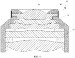
- the lens structure includes: a lens tube 10; a first lens 30 located on a first end-face of the lens tube 10, where the first lens 30 includes a light converging region and an edge region located at an edge around the light converging region; a light shielding structure 40 covering the edge region of the first lens 30; and at least one second lens 20 located inside the lens tube 10.
- the first end-face of the lens tube is a surface that is of the lens tube and that faces a side of a to-be-taken image when the lens structure is in a using state, that is, an outer surface that is of the lens tube and that faces a side of the first lens.
- the at least one second lens 20 includes a plurality of second lenses
- the plurality of second lenses may be the same or different. This is not limited in this embodiment of this application, and specifically depends on a particular case.
- the first lens 30 is fixedly bonded with the light shielding structure 40, and the first lens 30 is fixedly bonded with the lens tube 10, so that the light shielding structure 40 is used to cover the edge region of the first lens 30, to prevent a light ray in an external environment from entering the lens tube 10 through the edge region of the first lens 30.
- this is not limited in this embodiment of this application, and specifically depends on a particular case.
- the first lens 30 is fixedly bonded with the light shielding structure 40 by using a liquid adhesive or a double-sided adhesive, and the first lens 30 is also fixedly bonded with the lens tube 10 by using a liquid adhesive or a double-sided adhesive.
- the first lens 30 is fixedly bonded with the light shielding structure 40 by using a UV heat curing adhesive, and the first lens 30 is also fixedly bonded with the lens tube 10 by using a UV heat curing adhesive, to describe the lens structure provided in this embodiment of this application.
- this is not limited in this embodiment of this application, and specifically depends on a particular case.
- the light shielding structure 40 is a polyester film.
- a projected area that is of the light shielding structure 40 and that is in a plane parallel to the edge region of the first lens 30 is greater than a projected area that is of the edge region of the first lens 30 and that is in the plane parallel to the edge region of the first lens 30, so that the light shielding structure 40 completely covers the edge region of the first lens 30 and a side wall of the first lens 30, and a light ray in an external environment is prevented from entering the lens tube 10 through the edge region of the first lens 30 and the side wall of the first lens 30.
- the light shielding structure 40 includes: a plastic component 41.
- the plastic component 41 covers at least the edge region of the first lens 30, so that a depth of the first light transmission hole 50 is not less than a thickness of the light converging region of the first lens 30, to protect the light converging region of the first lens 30, and reduce a probability of wearing the light converging region of the first lens 30.
- the plastic component 41 is made of polycarbonate (Polycarbonate, PC for short), and the lens tube 10 is made of a material that is the same as that of the plastic component 41.
- polycarbonate Polycarbonate, PC for short
- the lens tube 10 is made of a material that is the same as that of the plastic component 41.
- this is not limited in this embodiment of this application, and specifically depends on a particular case.
- the plastic component 41 completely covers the edge region of the first lens 30 and the side wall of the first lens 30.
- the plastic component 41 includes a horizontal part and a vertical part.
- the horizontal part completely covers a surface of the edge region of the first lens 30, and the vertical part blocks the side wall of the first lens 30.
- a height of the vertical part is greater than a thickness of the side wall of the first lens 30, to prevent a light ray in an external environment from being incident on the first lens 30 in a plane parallel to the horizontal part.
- the plastic component 41 may completely cover the surface of the edge region and the side wall of the first lens 30, and another additional structure does not need to be disposed, so that a structure is relatively simple.
- the plastic component 41 covers only the surface of the edge region of the first lens 30.
- the light shielding structure 40 further includes a light shielding component 42.
- the light shielding component 42 covers at least the side wall of the edge region (that is, the side wall of the first lens 30), and is configured to shield light for the side wall of the first lens 30.
- the light shielding component 42 covers both side walls of the plastic component 41 and the first lens 30.
- the light shielding component 42 covers only the side wall of the first lens 30.
- the light shielding component 42 further extends along a thickness direction of the first lens 30 to cover a part of the side wall of the plastic component 41 and a part of a side wall of the lens tube 10.
- this is not limited in this embodiment of this application, and specifically depends on a particular case.
- the plastic component 41 and the light shielding component 42 combine to completely cover the surface of the edge region and the side wall of the first lens 30. This is not limited in this embodiment of this application, and specifically depends on a particular case.
- the light shielding structure 40 is also fixedly bonded with the lens tube 10.
- an embodiment of this application further provides a camera having the lens structure provided in any one of the foregoing embodiments.
- the camera includes: the lens structure provided in any one of the foregoing embodiments; a light sensing component located on a second end-face of the lens tube of the lens structure, where the second end-face is a face that is in the lens tube and that is opposite to the first end-face; and a circuit board, located on a side that is of the light sensing component and that is opposite to the lens structure, and electrically connected to the light sensing component.
- the circuit board may be a PCB circuit board, and this is not limited in this embodiment of this application.
- the lens tube structure is configured to collect light rays.
- the light sensing component is configured to: sense the light rays collected by the lens tube structure, convert the light rays to electrical signals, then convert the electrical signals to digital signals, and transmit the digital signals to the circuit board.
- the circuit board outputs the digital signals to the terminal.
- An image processing component of the terminal processes the digital signals to form an image.
- the first lens 30 is disposed outside the lens tube 10. Therefore, an adjustment degree is relatively high, and convenience and flexibility are relatively desirable.
- the first lens 30 and the lens tube 10 including the at least one second lens 20 are independently disposed. Therefore, the lens tube 10 including the at least one second lens 20 and a structure obtained after assembling the first lens 30 and the lens tube 10 can be separately tested, to distinguish whether a reason for a quality problem of the lens structure is an assembly problem of the at least one second lens 20 or a position arrangement problem of the first lens 30.
- an embodiment of this application further provides a lens structure fabrication method. As shown in FIG. 1 and FIG. 5 , the method includes:
- the providing a lens tube 10, where at least one second lens is disposed inside the lens tube 10 includes: providing a lens tube 10, where at least one second lens is disposed inside the lens tube 10; detecting a resolution of the lens tube 10 to determine an alignment degree of the at least one second lens in the lens tube 10; and when the resolution of the lens tube 10 satisfies a preset requirement, marking the lens tube 10 as a lens tube satisfying an assembly requirement, to be subsequently assembled with the first assembly structure.
- the light shielding structure 40 is a polyester film is used below to describe the lens structure fabrication method provided in this embodiment of this application.
- the fastening a first lens 30 on a first surface of the light shielding structure 40 to form a first assembly structure, where the first lens 30 includes a light converging region and an edge region located at an edge around the light converging region, and the first light transmission hole exposes the light converging region includes:
- a projected area that is of the light shielding structure 40 and that is in a plane parallel to the edge region of the first lens 30 is greater than a projected area that is of the edge region of the first lens 30 and that is in the plane parallel to the edge region of the first lens 30. Therefore, to facilitate subsequent fixed bonding between the light shielding structure 40 and the lens tube 10, a part that is of the bonding adhesive and that is located at the edge region is illuminated by using UV light, to perform UV curing for the first time.
- the method further includes: shielding a non-overlapped region of the polyester film and the first lens 30 by using an auxiliary light shielding structure, to maintain bonding performance of the non-overlapped region of the polyester film and the first lens 30.
- the fastening a first lens 30 on a first surface of the light shielding structure 40 to form a first assembly structure, where the first lens 30 includes a light converging region and an edge region located at an edge around the light converging region, and the first light transmission hole exposes the light converging region includes: coating a first surface of the plastic component 41 with a bonding adhesive, where the plastic component has a first light transmission hole, and the bonding adhesive includes a UV heat curing adhesive, as shown in FIG. 6 (A) and FIG.
- the first assembly structure is disposed on the first end-face of the lens tube 10.
- the first assembly structure is adjusted until the resolution of the lens structure is greater than the preset value.
- the lens tube 10 and the first assembly structure are fastened, as shown in FIG. 6 (C) .
- the light shielding component 42 is fastened, where the light shielding component 42 covers at least the side wall of the edge region.
- the placing the first assembly structure on a first end-face of the lens tube 10 includes:
- the adjusting the first assembly structure until a resolution of the lens structure is greater than a preset value includes:
- the clamping apparatus includes a suction nozzle and/or an adjustment machine using a dynamic adjustment technology.
- a suction nozzle and/or an adjustment machine using a dynamic adjustment technology.
- this is not limited in this embodiment of this application, and specifically depends on a particular case.
- the adjusting the first assembly structure until a resolution of the lens structure is greater than a preset value includes: disposing a light sensing component on a side that is of the lens tube 10 and that is opposite to the first end-face; fastening the light shielding structure 40 by using the clamping apparatus, and adjusting a position of the first lens 30 by moving the light shielding structure 40, so that optical axes of the first lens 30 and the at least one second lens 20 are aligned; collecting an image at each adjustment position by using the lens structure formed by the lens tube 10 and the first assembly structure; analyzing a definition resolution of the collected image to determine the resolution of the lens structure; when the resolution of the lens structure is not greater than the preset value, adjusting the position of the first assembly structure; repeating the foregoing image collection and analysis process until the resolution of the lens structure is greater than the preset value; and fastening a current position of the lens structure.
- the method further includes: applying pressure and leveling around the light shielding structure 40, so that air-tightness of the light shielding structure 40, the first lens 30, and the lens tube 10 is facilitated, and a light shielding effect is improved while an ideal shape is obtained.
- the fastening the lens tube 10 and the first assembly structure includes:
- the entire lens structure is most sensitive to an alignment degree of an optical axis position of the first lens in the lens structure.
- the first lens 30 is disposed on an outer side of a housing of the lens tube. Therefore, an adjustment degree is relatively high, and convenience and flexibility are relatively desirable.
- the position of the first lens 30 is fastened, so that an optical axis of the first lens 30 and an optical axis of the at least one second lens 20 are aligned at a relatively high extent, thereby improving quality of the lens structure.
- the first lens 30 and the at least one second lens 20 are independently disposed. Therefore, the lens tube including the at least one second lens 20 and a structure obtained after assembling the first lens 30 and the lens tube can be separately tested, to distinguish whether a reason for a quality problem of the lens structure is an assembly problem of the at least one second lens 20 or a position arrangement problem of the first lens 30.
Landscapes
- Physics & Mathematics (AREA)
- General Physics & Mathematics (AREA)
- Optics & Photonics (AREA)
- Engineering & Computer Science (AREA)
- Multimedia (AREA)
- Signal Processing (AREA)
- Lens Barrels (AREA)
- Eyeglasses (AREA)
Priority Applications (1)
| Application Number | Priority Date | Filing Date | Title |
|---|---|---|---|
| EP22216943.5A EP4220265B1 (de) | 2017-01-03 | 2017-04-25 | Linsenstruktur, verfahren zur herstellung einer linsenstruktur und kamera |
Applications Claiming Priority (2)
| Application Number | Priority Date | Filing Date | Title |
|---|---|---|---|
| CN201710002830 | 2017-01-03 | ||
| PCT/CN2017/081820 WO2018126565A1 (zh) | 2017-01-03 | 2017-04-25 | 一种镜头结构及其制作方法、摄像头 |
Related Child Applications (2)
| Application Number | Title | Priority Date | Filing Date |
|---|---|---|---|
| EP22216943.5A Division EP4220265B1 (de) | 2017-01-03 | 2017-04-25 | Linsenstruktur, verfahren zur herstellung einer linsenstruktur und kamera |
| EP22216943.5A Division-Into EP4220265B1 (de) | 2017-01-03 | 2017-04-25 | Linsenstruktur, verfahren zur herstellung einer linsenstruktur und kamera |
Publications (3)
| Publication Number | Publication Date |
|---|---|
| EP3553581A1 true EP3553581A1 (de) | 2019-10-16 |
| EP3553581A4 EP3553581A4 (de) | 2020-01-01 |
| EP3553581B1 EP3553581B1 (de) | 2023-03-01 |
Family
ID=62788860
Family Applications (2)
| Application Number | Title | Priority Date | Filing Date |
|---|---|---|---|
| EP22216943.5A Active EP4220265B1 (de) | 2017-01-03 | 2017-04-25 | Linsenstruktur, verfahren zur herstellung einer linsenstruktur und kamera |
| EP17889835.9A Active EP3553581B1 (de) | 2017-01-03 | 2017-04-25 | Linsenstruktur, herstellungsverfahren dafür und kamera |
Family Applications Before (1)
| Application Number | Title | Priority Date | Filing Date |
|---|---|---|---|
| EP22216943.5A Active EP4220265B1 (de) | 2017-01-03 | 2017-04-25 | Linsenstruktur, verfahren zur herstellung einer linsenstruktur und kamera |
Country Status (5)
| Country | Link |
|---|---|
| US (1) | US11249276B2 (de) |
| EP (2) | EP4220265B1 (de) |
| CN (1) | CN108780204B (de) |
| ES (2) | ES2940444T3 (de) |
| WO (1) | WO2018126565A1 (de) |
Families Citing this family (11)
| Publication number | Priority date | Publication date | Assignee | Title |
|---|---|---|---|---|
| CN109302515A (zh) * | 2018-11-30 | 2019-02-01 | 上海摩软通讯技术有限公司 | 镜片安装结构及移动终端 |
| CN109358402A (zh) * | 2018-12-17 | 2019-02-19 | 浙江舜宇光学有限公司 | 成像镜头 |
| CN209387985U (zh) * | 2018-12-31 | 2019-09-13 | 瑞声科技(新加坡)有限公司 | 镜头模组及电子设备 |
| CN110109226B (zh) * | 2019-04-12 | 2021-11-12 | 深圳市万普拉斯科技有限公司 | 镜头结构、摄像头模组及移动终端 |
| CN119676548A (zh) * | 2019-07-11 | 2025-03-21 | 华为技术有限公司 | 一种镜头、摄像头和电子设备 |
| CN112444934B (zh) * | 2019-08-14 | 2024-10-29 | 宁波舜宇光电信息有限公司 | 屏下摄像组件、摄像模组和光学镜头及其制作方法 |
| GB201917386D0 (en) * | 2019-11-28 | 2020-01-15 | Knapton Property Man Services Limited | Lens |
| CN113835278B (zh) * | 2020-06-08 | 2023-12-08 | 宁波舜宇光电信息有限公司 | 光学镜头、摄像模组和光学镜头的组装方法 |
| WO2022141062A1 (zh) * | 2020-12-29 | 2022-07-07 | 欧菲光集团股份有限公司 | 摄像头模组和电子设备 |
| CN114791654A (zh) * | 2021-01-08 | 2022-07-26 | 宁波舜宇光电信息有限公司 | 镜头和带有镜头的摄像模组 |
| CN113126229B (zh) * | 2021-04-30 | 2024-05-03 | 维沃移动通信有限公司 | 镜头模组及电子设备 |
Family Cites Families (17)
| Publication number | Priority date | Publication date | Assignee | Title |
|---|---|---|---|---|
| TWI279587B (en) * | 2004-05-27 | 2007-04-21 | Asia Optical Co Inc | Lens member having a light shading function |
| US9621772B2 (en) | 2006-11-09 | 2017-04-11 | Digitaloptics Corporation | Integrated lens barrel, actuator, and MEMS snubber systems and methods |
| KR20120067104A (ko) | 2010-12-15 | 2012-06-25 | 삼성전기주식회사 | 카메라 모듈 |
| CN102998764A (zh) | 2011-09-15 | 2013-03-27 | 鸿富锦精密工业(深圳)有限公司 | 镜头模组 |
| CN103842876B (zh) * | 2011-09-30 | 2016-01-27 | 富士胶片株式会社 | 透镜单元及其制造方法 |
| TW201411217A (zh) | 2012-09-14 | 2014-03-16 | Hon Hai Prec Ind Co Ltd | 鏡頭模組 |
| CN103728705B (zh) | 2012-10-16 | 2017-03-08 | 玉晶光电(厦门)有限公司 | 可消除杂散光线的成像镜头 |
| CN103813069A (zh) | 2012-11-13 | 2014-05-21 | 无锡华御信息技术有限公司 | 具有高清摄像头的影像系统 |
| JP2016106239A (ja) | 2013-03-27 | 2016-06-16 | 富士フイルム株式会社 | レンズユニット、撮像モジュール、及び電子機器 |
| CN203232191U (zh) | 2013-04-23 | 2013-10-09 | 昆山凯尔光电科技有限公司 | 一种定焦模组 |
| CN103246039A (zh) * | 2013-04-23 | 2013-08-14 | 昆山凯尔光电科技有限公司 | 一种定焦模组及其组装工艺 |
| JP6116417B2 (ja) * | 2013-07-12 | 2017-04-19 | 富士フイルム株式会社 | 光学レンズ、レンズユニット、撮像モジュール、電子機器 |
| KR101983169B1 (ko) * | 2014-04-18 | 2019-05-28 | 삼성전기주식회사 | 렌즈 모듈, 렌즈 모듈의 제조 방법 및 렌즈 모듈을 포함하는 카메라 모듈 |
| KR102255446B1 (ko) * | 2014-08-04 | 2021-05-24 | 엘지이노텍 주식회사 | 차량용 카메라 모듈 |
| KR101823195B1 (ko) * | 2014-12-23 | 2018-01-29 | 삼성전기주식회사 | 렌즈 조립체 및 이를 구비하는 카메라 모듈 |
| CN106324784B (zh) * | 2015-06-17 | 2018-11-02 | 玉晶光电(厦门)有限公司 | 具有背胶型遮光组件的镜头 |
| CN105549173A (zh) | 2016-01-28 | 2016-05-04 | 宁波舜宇光电信息有限公司 | 光学镜头和摄像模组及其组装方法 |
-
2017
- 2017-04-25 ES ES17889835T patent/ES2940444T3/es active Active
- 2017-04-25 WO PCT/CN2017/081820 patent/WO2018126565A1/zh not_active Ceased
- 2017-04-25 EP EP22216943.5A patent/EP4220265B1/de active Active
- 2017-04-25 US US16/475,488 patent/US11249276B2/en active Active
- 2017-04-25 ES ES22216943T patent/ES3004693T3/es active Active
- 2017-04-25 CN CN201780005261.4A patent/CN108780204B/zh active Active
- 2017-04-25 EP EP17889835.9A patent/EP3553581B1/de active Active
Also Published As
| Publication number | Publication date |
|---|---|
| ES2940444T3 (es) | 2023-05-08 |
| US20200174217A1 (en) | 2020-06-04 |
| EP4220265A3 (de) | 2023-10-11 |
| EP3553581B1 (de) | 2023-03-01 |
| EP4220265A2 (de) | 2023-08-02 |
| EP4220265B1 (de) | 2024-12-04 |
| WO2018126565A1 (zh) | 2018-07-12 |
| US11249276B2 (en) | 2022-02-15 |
| ES3004693T3 (en) | 2025-03-12 |
| CN108780204B (zh) | 2020-11-17 |
| EP3553581A4 (de) | 2020-01-01 |
| CN108780204A (zh) | 2018-11-09 |
Similar Documents
| Publication | Publication Date | Title |
|---|---|---|
| EP4220265B1 (de) | Linsenstruktur, verfahren zur herstellung einer linsenstruktur und kamera | |
| US20220239816A1 (en) | Integrated image sensor and lens assembly | |
| KR102405359B1 (ko) | 촬영모듈 및 그 몰드감광 어셈블리와 제조방법, 및 전자장치 | |
| CN209895062U (zh) | 摄像镜头以及摄像头模块 | |
| TWI728690B (zh) | 成像鏡頭、相機模組及電子裝置 | |
| TWI703342B (zh) | 成像鏡頭模組及電子裝置 | |
| KR20220003148A (ko) | 렌즈와 카메라모듈 및 그 제조방법 | |
| CN108873246A (zh) | 含有塑胶透镜的成像透镜组、成像镜头模块及电子装置 | |
| CN114503540B (zh) | 包括相机模块的电子设备 | |
| JP2017090875A (ja) | レンズモジュール | |
| WO2015009237A1 (en) | Camera module including a non-circular lens | |
| US11029481B2 (en) | Lens module | |
| US11131905B2 (en) | Camera module and electronic device | |
| EP3594730B1 (de) | Linseneinheit, bearbeitungsverfahren für linseneinheit, kameramodul und elektronische vorrichtung | |
| US20180164533A1 (en) | Lens and Lens Module | |
| US11029482B2 (en) | Pressing ring and lens module | |
| CN201853708U (zh) | 影像感测装置 | |
| CN105319802B (zh) | 相机模块 | |
| JP6810210B2 (ja) | レンズモジュール | |
| CN215818343U (zh) | 摄像头支架、摄像头组件及电子设备 | |
| US20200357842A1 (en) | Image sensor module having protective structure that blocks incident light to arrive at bonding wires and pads | |
| WO2021031732A1 (zh) | 分体式镜头及其组装方法、摄像模组和终端设备 | |
| KR102878285B1 (ko) | 카메라 장치 | |
| KR20180045275A (ko) | 카메라 모듈 | |
| KR101754737B1 (ko) | 칩 온 보드 센서 부착용 렌즈 스탠드 오프를 구비한 카메라 모듈 |
Legal Events
| Date | Code | Title | Description |
|---|---|---|---|
| STAA | Information on the status of an ep patent application or granted ep patent |
Free format text: STATUS: THE INTERNATIONAL PUBLICATION HAS BEEN MADE |
|
| PUAI | Public reference made under article 153(3) epc to a published international application that has entered the european phase |
Free format text: ORIGINAL CODE: 0009012 |
|
| STAA | Information on the status of an ep patent application or granted ep patent |
Free format text: STATUS: REQUEST FOR EXAMINATION WAS MADE |
|
| 17P | Request for examination filed |
Effective date: 20190711 |
|
| AK | Designated contracting states |
Kind code of ref document: A1 Designated state(s): AL AT BE BG CH CY CZ DE DK EE ES FI FR GB GR HR HU IE IS IT LI LT LU LV MC MK MT NL NO PL PT RO RS SE SI SK SM TR |
|
| AX | Request for extension of the european patent |
Extension state: BA ME |
|
| A4 | Supplementary search report drawn up and despatched |
Effective date: 20191204 |
|
| RIC1 | Information provided on ipc code assigned before grant |
Ipc: H04N 5/225 20060101ALI20191128BHEP Ipc: G02B 7/02 20060101AFI20191128BHEP Ipc: G03B 17/02 20060101ALI20191128BHEP |
|
| DAV | Request for validation of the european patent (deleted) | ||
| DAX | Request for extension of the european patent (deleted) | ||
| GRAP | Despatch of communication of intention to grant a patent |
Free format text: ORIGINAL CODE: EPIDOSNIGR1 |
|
| STAA | Information on the status of an ep patent application or granted ep patent |
Free format text: STATUS: GRANT OF PATENT IS INTENDED |
|
| INTG | Intention to grant announced |
Effective date: 20220916 |
|
| GRAS | Grant fee paid |
Free format text: ORIGINAL CODE: EPIDOSNIGR3 |
|
| GRAA | (expected) grant |
Free format text: ORIGINAL CODE: 0009210 |
|
| STAA | Information on the status of an ep patent application or granted ep patent |
Free format text: STATUS: THE PATENT HAS BEEN GRANTED |
|
| AK | Designated contracting states |
Kind code of ref document: B1 Designated state(s): AL AT BE BG CH CY CZ DE DK EE ES FI FR GB GR HR HU IE IS IT LI LT LU LV MC MK MT NL NO PL PT RO RS SE SI SK SM TR |
|
| REG | Reference to a national code |
Ref country code: GB Ref legal event code: FG4D |
|
| REG | Reference to a national code |
Ref country code: CH Ref legal event code: EP Ref country code: AT Ref legal event code: REF Ref document number: 1551387 Country of ref document: AT Kind code of ref document: T Effective date: 20230315 |
|
| REG | Reference to a national code |
Ref country code: DE Ref legal event code: R096 Ref document number: 602017066511 Country of ref document: DE |
|
| REG | Reference to a national code |
Ref country code: IE Ref legal event code: FG4D |
|
| REG | Reference to a national code |
Ref country code: ES Ref legal event code: FG2A Ref document number: 2940444 Country of ref document: ES Kind code of ref document: T3 Effective date: 20230508 |
|
| P01 | Opt-out of the competence of the unified patent court (upc) registered |
Effective date: 20230510 |
|
| REG | Reference to a national code |
Ref country code: LT Ref legal event code: MG9D |
|
| REG | Reference to a national code |
Ref country code: NL Ref legal event code: MP Effective date: 20230301 |
|
| PG25 | Lapsed in a contracting state [announced via postgrant information from national office to epo] |
Ref country code: RS Free format text: LAPSE BECAUSE OF FAILURE TO SUBMIT A TRANSLATION OF THE DESCRIPTION OR TO PAY THE FEE WITHIN THE PRESCRIBED TIME-LIMIT Effective date: 20230301 Ref country code: NO Free format text: LAPSE BECAUSE OF FAILURE TO SUBMIT A TRANSLATION OF THE DESCRIPTION OR TO PAY THE FEE WITHIN THE PRESCRIBED TIME-LIMIT Effective date: 20230601 Ref country code: LV Free format text: LAPSE BECAUSE OF FAILURE TO SUBMIT A TRANSLATION OF THE DESCRIPTION OR TO PAY THE FEE WITHIN THE PRESCRIBED TIME-LIMIT Effective date: 20230301 Ref country code: LT Free format text: LAPSE BECAUSE OF FAILURE TO SUBMIT A TRANSLATION OF THE DESCRIPTION OR TO PAY THE FEE WITHIN THE PRESCRIBED TIME-LIMIT Effective date: 20230301 Ref country code: HR Free format text: LAPSE BECAUSE OF FAILURE TO SUBMIT A TRANSLATION OF THE DESCRIPTION OR TO PAY THE FEE WITHIN THE PRESCRIBED TIME-LIMIT Effective date: 20230301 |
|
| REG | Reference to a national code |
Ref country code: AT Ref legal event code: MK05 Ref document number: 1551387 Country of ref document: AT Kind code of ref document: T Effective date: 20230301 |
|
| PG25 | Lapsed in a contracting state [announced via postgrant information from national office to epo] |
Ref country code: SE Free format text: LAPSE BECAUSE OF FAILURE TO SUBMIT A TRANSLATION OF THE DESCRIPTION OR TO PAY THE FEE WITHIN THE PRESCRIBED TIME-LIMIT Effective date: 20230301 Ref country code: PL Free format text: LAPSE BECAUSE OF FAILURE TO SUBMIT A TRANSLATION OF THE DESCRIPTION OR TO PAY THE FEE WITHIN THE PRESCRIBED TIME-LIMIT Effective date: 20230301 Ref country code: NL Free format text: LAPSE BECAUSE OF FAILURE TO SUBMIT A TRANSLATION OF THE DESCRIPTION OR TO PAY THE FEE WITHIN THE PRESCRIBED TIME-LIMIT Effective date: 20230301 Ref country code: GR Free format text: LAPSE BECAUSE OF FAILURE TO SUBMIT A TRANSLATION OF THE DESCRIPTION OR TO PAY THE FEE WITHIN THE PRESCRIBED TIME-LIMIT Effective date: 20230602 Ref country code: FI Free format text: LAPSE BECAUSE OF FAILURE TO SUBMIT A TRANSLATION OF THE DESCRIPTION OR TO PAY THE FEE WITHIN THE PRESCRIBED TIME-LIMIT Effective date: 20230301 |
|
| PG25 | Lapsed in a contracting state [announced via postgrant information from national office to epo] |
Ref country code: SM Free format text: LAPSE BECAUSE OF FAILURE TO SUBMIT A TRANSLATION OF THE DESCRIPTION OR TO PAY THE FEE WITHIN THE PRESCRIBED TIME-LIMIT Effective date: 20230301 Ref country code: RO Free format text: LAPSE BECAUSE OF FAILURE TO SUBMIT A TRANSLATION OF THE DESCRIPTION OR TO PAY THE FEE WITHIN THE PRESCRIBED TIME-LIMIT Effective date: 20230301 Ref country code: PT Free format text: LAPSE BECAUSE OF FAILURE TO SUBMIT A TRANSLATION OF THE DESCRIPTION OR TO PAY THE FEE WITHIN THE PRESCRIBED TIME-LIMIT Effective date: 20230703 Ref country code: EE Free format text: LAPSE BECAUSE OF FAILURE TO SUBMIT A TRANSLATION OF THE DESCRIPTION OR TO PAY THE FEE WITHIN THE PRESCRIBED TIME-LIMIT Effective date: 20230301 Ref country code: CZ Free format text: LAPSE BECAUSE OF FAILURE TO SUBMIT A TRANSLATION OF THE DESCRIPTION OR TO PAY THE FEE WITHIN THE PRESCRIBED TIME-LIMIT Effective date: 20230301 Ref country code: AT Free format text: LAPSE BECAUSE OF FAILURE TO SUBMIT A TRANSLATION OF THE DESCRIPTION OR TO PAY THE FEE WITHIN THE PRESCRIBED TIME-LIMIT Effective date: 20230301 |
|
| PG25 | Lapsed in a contracting state [announced via postgrant information from national office to epo] |
Ref country code: SK Free format text: LAPSE BECAUSE OF FAILURE TO SUBMIT A TRANSLATION OF THE DESCRIPTION OR TO PAY THE FEE WITHIN THE PRESCRIBED TIME-LIMIT Effective date: 20230301 Ref country code: IS Free format text: LAPSE BECAUSE OF FAILURE TO SUBMIT A TRANSLATION OF THE DESCRIPTION OR TO PAY THE FEE WITHIN THE PRESCRIBED TIME-LIMIT Effective date: 20230701 |
|
| REG | Reference to a national code |
Ref country code: CH Ref legal event code: PL |
|
| REG | Reference to a national code |
Ref country code: DE Ref legal event code: R097 Ref document number: 602017066511 Country of ref document: DE |
|
| PG25 | Lapsed in a contracting state [announced via postgrant information from national office to epo] |
Ref country code: LU Free format text: LAPSE BECAUSE OF NON-PAYMENT OF DUE FEES Effective date: 20230425 |
|
| PLBE | No opposition filed within time limit |
Free format text: ORIGINAL CODE: 0009261 |
|
| STAA | Information on the status of an ep patent application or granted ep patent |
Free format text: STATUS: NO OPPOSITION FILED WITHIN TIME LIMIT |
|
| REG | Reference to a national code |
Ref country code: BE Ref legal event code: MM Effective date: 20230430 |
|
| PG25 | Lapsed in a contracting state [announced via postgrant information from national office to epo] |
Ref country code: MC Free format text: LAPSE BECAUSE OF FAILURE TO SUBMIT A TRANSLATION OF THE DESCRIPTION OR TO PAY THE FEE WITHIN THE PRESCRIBED TIME-LIMIT Effective date: 20230301 |
|
| PG25 | Lapsed in a contracting state [announced via postgrant information from national office to epo] |
Ref country code: SI Free format text: LAPSE BECAUSE OF FAILURE TO SUBMIT A TRANSLATION OF THE DESCRIPTION OR TO PAY THE FEE WITHIN THE PRESCRIBED TIME-LIMIT Effective date: 20230301 Ref country code: MC Free format text: LAPSE BECAUSE OF FAILURE TO SUBMIT A TRANSLATION OF THE DESCRIPTION OR TO PAY THE FEE WITHIN THE PRESCRIBED TIME-LIMIT Effective date: 20230301 Ref country code: LI Free format text: LAPSE BECAUSE OF NON-PAYMENT OF DUE FEES Effective date: 20230430 Ref country code: DK Free format text: LAPSE BECAUSE OF FAILURE TO SUBMIT A TRANSLATION OF THE DESCRIPTION OR TO PAY THE FEE WITHIN THE PRESCRIBED TIME-LIMIT Effective date: 20230301 Ref country code: CH Free format text: LAPSE BECAUSE OF NON-PAYMENT OF DUE FEES Effective date: 20230430 |
|
| 26N | No opposition filed |
Effective date: 20231204 |
|
| REG | Reference to a national code |
Ref country code: IE Ref legal event code: MM4A |
|
| PG25 | Lapsed in a contracting state [announced via postgrant information from national office to epo] |
Ref country code: BE Free format text: LAPSE BECAUSE OF NON-PAYMENT OF DUE FEES Effective date: 20230430 |
|
| PG25 | Lapsed in a contracting state [announced via postgrant information from national office to epo] |
Ref country code: IE Free format text: LAPSE BECAUSE OF NON-PAYMENT OF DUE FEES Effective date: 20230425 |
|
| PG25 | Lapsed in a contracting state [announced via postgrant information from national office to epo] |
Ref country code: IE Free format text: LAPSE BECAUSE OF NON-PAYMENT OF DUE FEES Effective date: 20230425 |
|
| PG25 | Lapsed in a contracting state [announced via postgrant information from national office to epo] |
Ref country code: IT Free format text: LAPSE BECAUSE OF FAILURE TO SUBMIT A TRANSLATION OF THE DESCRIPTION OR TO PAY THE FEE WITHIN THE PRESCRIBED TIME-LIMIT Effective date: 20230301 |
|
| PG25 | Lapsed in a contracting state [announced via postgrant information from national office to epo] |
Ref country code: BG Free format text: LAPSE BECAUSE OF FAILURE TO SUBMIT A TRANSLATION OF THE DESCRIPTION OR TO PAY THE FEE WITHIN THE PRESCRIBED TIME-LIMIT Effective date: 20230301 |
|
| PG25 | Lapsed in a contracting state [announced via postgrant information from national office to epo] |
Ref country code: BG Free format text: LAPSE BECAUSE OF FAILURE TO SUBMIT A TRANSLATION OF THE DESCRIPTION OR TO PAY THE FEE WITHIN THE PRESCRIBED TIME-LIMIT Effective date: 20230301 |
|
| PGFP | Annual fee paid to national office [announced via postgrant information from national office to epo] |
Ref country code: FR Payment date: 20250310 Year of fee payment: 9 |
|
| PGFP | Annual fee paid to national office [announced via postgrant information from national office to epo] |
Ref country code: GB Payment date: 20250306 Year of fee payment: 9 |
|
| PGFP | Annual fee paid to national office [announced via postgrant information from national office to epo] |
Ref country code: DE Payment date: 20250305 Year of fee payment: 9 |
|
| PGFP | Annual fee paid to national office [announced via postgrant information from national office to epo] |
Ref country code: ES Payment date: 20250509 Year of fee payment: 9 |
|
| PG25 | Lapsed in a contracting state [announced via postgrant information from national office to epo] |
Ref country code: CY Free format text: LAPSE BECAUSE OF FAILURE TO SUBMIT A TRANSLATION OF THE DESCRIPTION OR TO PAY THE FEE WITHIN THE PRESCRIBED TIME-LIMIT; INVALID AB INITIO Effective date: 20170425 |
|
| PG25 | Lapsed in a contracting state [announced via postgrant information from national office to epo] |
Ref country code: HU Free format text: LAPSE BECAUSE OF FAILURE TO SUBMIT A TRANSLATION OF THE DESCRIPTION OR TO PAY THE FEE WITHIN THE PRESCRIBED TIME-LIMIT; INVALID AB INITIO Effective date: 20170425 |
|
| PG25 | Lapsed in a contracting state [announced via postgrant information from national office to epo] |
Ref country code: TR Free format text: LAPSE BECAUSE OF FAILURE TO SUBMIT A TRANSLATION OF THE DESCRIPTION OR TO PAY THE FEE WITHIN THE PRESCRIBED TIME-LIMIT Effective date: 20230301 |