EP3553564B1 - Capteur mesurant la distance - Google Patents
Capteur mesurant la distance Download PDFInfo
- Publication number
- EP3553564B1 EP3553564B1 EP19163963.2A EP19163963A EP3553564B1 EP 3553564 B1 EP3553564 B1 EP 3553564B1 EP 19163963 A EP19163963 A EP 19163963A EP 3553564 B1 EP3553564 B1 EP 3553564B1
- Authority
- EP
- European Patent Office
- Prior art keywords
- sensor
- light beam
- light
- section
- reflected
- Prior art date
- Legal status (The legal status is an assumption and is not a legal conclusion. Google has not performed a legal analysis and makes no representation as to the accuracy of the status listed.)
- Active
Links
Images

Classifications
-
- G—PHYSICS
- G01—MEASURING; TESTING
- G01S—RADIO DIRECTION-FINDING; RADIO NAVIGATION; DETERMINING DISTANCE OR VELOCITY BY USE OF RADIO WAVES; LOCATING OR PRESENCE-DETECTING BY USE OF THE REFLECTION OR RERADIATION OF RADIO WAVES; ANALOGOUS ARRANGEMENTS USING OTHER WAVES
- G01S17/00—Systems using the reflection or reradiation of electromagnetic waves other than radio waves, e.g. lidar systems
- G01S17/02—Systems using the reflection of electromagnetic waves other than radio waves
- G01S17/06—Systems determining position data of a target
- G01S17/42—Simultaneous measurement of distance and other co-ordinates
-
- G—PHYSICS
- G01—MEASURING; TESTING
- G01S—RADIO DIRECTION-FINDING; RADIO NAVIGATION; DETERMINING DISTANCE OR VELOCITY BY USE OF RADIO WAVES; LOCATING OR PRESENCE-DETECTING BY USE OF THE REFLECTION OR RERADIATION OF RADIO WAVES; ANALOGOUS ARRANGEMENTS USING OTHER WAVES
- G01S7/00—Details of systems according to groups G01S13/00, G01S15/00, G01S17/00
- G01S7/48—Details of systems according to groups G01S13/00, G01S15/00, G01S17/00 of systems according to group G01S17/00
- G01S7/481—Constructional features, e.g. arrangements of optical elements
- G01S7/4811—Constructional features, e.g. arrangements of optical elements common to transmitter and receiver
- G01S7/4812—Constructional features, e.g. arrangements of optical elements common to transmitter and receiver transmitted and received beams following a coaxial path
-
- G—PHYSICS
- G01—MEASURING; TESTING
- G01S—RADIO DIRECTION-FINDING; RADIO NAVIGATION; DETERMINING DISTANCE OR VELOCITY BY USE OF RADIO WAVES; LOCATING OR PRESENCE-DETECTING BY USE OF THE REFLECTION OR RERADIATION OF RADIO WAVES; ANALOGOUS ARRANGEMENTS USING OTHER WAVES
- G01S7/00—Details of systems according to groups G01S13/00, G01S15/00, G01S17/00
- G01S7/48—Details of systems according to groups G01S13/00, G01S15/00, G01S17/00 of systems according to group G01S17/00
- G01S7/481—Constructional features, e.g. arrangements of optical elements
- G01S7/4811—Constructional features, e.g. arrangements of optical elements common to transmitter and receiver
- G01S7/4813—Housing arrangements
Definitions
- the present invention relates to a distance measuring sensor which has a light source for generating a transmission light beam, at least one focusing element for detecting light of the transmission light beam reflected or remitted on an object and a detection element which is provided for detecting the light which is passed through the focusing element is captured.
- TOF sensor time-of-flight sensor
- the transit time of the light is determined, for example between the light source and the detection element, in order to use the transit time and the speed of light to determine the distance between the sensor and the Measure object on which the transmitted light beam is reflected or remitted.
- the transit time can be, for example, the transit time of a light pulse.
- the phase shift of a modulated signal is evaluated, which, however, also corresponds to an at least indirect determination of the light transit time. In this respect, such an evaluation of a phase shift is also subsumed under the term light transit time determination in the present text.
- Such TOF sensors are used, for example, for object recognition or in scanners, with a predetermined spatial area being scanned, for example, by means of a laser as the light source.
- the light source and the focusing element are each arranged in a separate transmitting area or receiving area, the light source and the focusing element being mutually exclusive and the transmitting light beam thus being optically isolated from the focusing element and the detection element within the sensor. Because of the spatial Separation of the transmitting and receiving areas, which is achieved, for example, with a separating web, such a sensor is also referred to as a sensor with "double eyes".
- the separating web usually only extends as far as a front pane of the sensor, which closes a housing of the sensor from the outside space.
- Both the transmitted light beam and a receiving path of the light that is to be detected by means of the focusing element thus run through the front pane.
- optical crosstalk between the transmitted light beam and the focusing element can occur via the front pane.
- the light of the transmitted light beam reaches the focusing element and thus the detection element of the sensor directly via the front pane, without having previously been reflected on an object outside the sensor.
- This crosstalk falsifies the measurement signal that is generated by the detection element and leads to systematic measurement errors.
- either the focusing element is arranged as far away from the transmitted light beam as possible in the direction of the front screen extension, or two separate front screens are provided for the sending and receiving areas of the sensor .
- a triangulation effect occurs, with two sides of the triangle being formed by the transmission light beam and the reception path between the object and the sensor and the third side of the triangle corresponding to the distance between the focal point of the focusing element and the transmission light beam.
- Such a triangulation causes a light spot, which by means of the focusing element by capturing and focusing the reflected from the object or remitted light is formed on the detection element, shifts within a certain range when the distance between the object and the sensor changes. Furthermore, due to the triangulation, ie due to the always existing angle of inclination between the normal to the windshield and the receiving path, multiple scattering can occur within the windshield, which represent a disruptive effect for the measurement signal of the sensor.
- the detection element comprises an array of receiving cells, which are arranged, for example, on a square surface, some of the cells only receive scattered light that was not reflected or remitted by the object as desired. This worsens the signal-to-noise ratio of the measurement signal generated by the detection element. Due to the displacement of the light spot, which is caused by the triangulation when the distance between the object and the sensor changes, it is also difficult to subsequently separate the measurement signal, which is created by the reflected or remitted light to be detected, from the signal. caused by the unwanted scattered light.
- the EP 2 645 125 A1 describes a distance measuring sensor having features according to related technology.
- the DE 10 2011 119 707 A1 describes an optical measuring device with a windshield, in which the surface of a first section of the windshield is inclined with respect to the surface of a second section of the windshield.
- One object of the invention is to further develop a sensor of the type mentioned at the beginning in such a way that the intensity of undesired light that enters the sensor in addition to the reflected or remitted light to be detected is minimized.
- a distance measuring sensor with the features of claim 1.
- a transmission light beam which is generated by means of a light source of the sensor, and a receiving path of light of the transmission light beam, which is reflected or remitted on an object and is detected by a focusing element of the sensor, are aligned essentially parallel to one another in front of the focusing element.
- the transmission light beam and the reception path of the light to be detected in front of the focusing element are preferably aligned completely parallel to one another.
- the sensor according to the invention further comprises a detection element for detecting the light detected by the focusing element and an evaluation unit which is designed to determine the transit time of the light between the light source and the detection element. On the basis of the determined transit time, the distance between the sensor and the object is also determined, as described above.
- the transit time can be, for example, the transit time of a light pulse.
- the phase shift of a modulated signal is evaluated, which, however, also corresponds to an at least indirect determination of the light transit time. In this respect, such an evaluation of a phase shift is also subsumed under the term light transit time determination in the present text.
- the above-described effects of triangulation can be minimized, that is to say the effects mentioned at the beginning that are caused by a Angle of inclination between the transmission light beam and the receiving path are caused.
- the lateral distance between the transmission light beam and a focal point of the focusing element is preferably as small as possible, so that the transmission light beam runs almost through the focal point or through a focal area of the focusing element.
- the focusing element preferably surrounds an area through which the transmitted light beam runs.
- the focusing element illuminates a light spot on the detection element, the position of which hardly changes when the distance between the sensor and an object on which the transmitted light beam is reflected or remitted varies .
- the detection element can be precisely arranged or adjusted at the end of the reception path, as a result of which the size of a measurement signal that is generated by the detection element is maximized and its signal-to-noise ratio is improved.
- the parallel alignment between the transmission light beam and the reception path enables a large focal length of the focusing element. This enlarges the scanning area in which a distance measurement by means of the sensor is possible. Due to the large focal length, an intermediate image can be generated in a plane between the focusing element and the detection element. The beam path between the focusing element and the detection element can be precisely defined by means of the intermediate image. As a result, the intensity of the light that reaches the detection element can in turn be optimized, so that the signal-to-noise ratio of the signal that is generated by the detection element is further improved.
- the detection element comprises, in particular, a field or array of receiving cells
- an active area or a “region of interest” can be placed on it (ROI) "because the position of the area or light spot illuminated by the focusing element on the detection element does not change due to the parallel alignment between the transmission light beam and the receiving path. Only those receiving cells of the detection element are activated that are actually in the area of the light spot , while those receiving cells are deactivated that are not reached by the reflected or remitted light of the transmitted light beam to be detected, but instead only pick up unwanted scattered light, which in turn improves the signal-to-noise ratio of the measurement signal from the sensor.
- An array of receiving elements forming the detection element can be made smaller than comparable arrays according to the prior art due to the precise and virtually unchanged position of the light point to be detected.
- the number of receiving elements to be read out is lower, so that a data reduction can be achieved.
- the receiving elements can be read out within a shorter period of time.
- the respectively active area within the array can be flexibly adapted to the changed reception path in the event of an exchange or a change of components within the reception path of the light to be detected.
- the sensor also has a front pane through which the transmitted light beam and the reflected or remitted light to be detected pass.
- the front pane has a separating element which divides the front pane into a first section, through which the transmitted light beam passes, and a second section, through which the reflected or remitted light to be detected passes. Furthermore, the separating element extends in the direction of the transmitted light beam over the entire cross section of the front pane.
- the reception path of the sensor in the area of the front pane is completely optically isolated from the transmitted light beam.
- the separating element consequently prevents part of the light from the transmitted light beam from reaching the focusing element directly via the front pane without being reflected or remitted as desired on an object.
- the intensity of undesired scattered light in the receiving path is in turn reduced, so that, conversely, the signal-to-noise ratio of the measurement signal is further improved.
- the surface of the second section of the front pane is arranged at right angles with respect to the transmitted light beam. Furthermore, the surface of the first section of the windshield is inclined with respect to the surface of the second section. An angle of inclination between the respective surfaces of the first or second section of the front pane preferably has a size of at most 5 degrees and particularly preferably a size of at most 1 degree.
- the inclination of the surface, in particular of the first section of the front pane can prevent light from the transmitted light beam from being reflected back into the light source on the front pane. This is particularly advantageous if the light source is designed as a laser, since an influencing of the laser power by such back reflection is excluded if the first section of the front pane is inclined.
- a monitor diode that may be present in such a laser is likewise not influenced by back reflection when the first section of the front pane is inclined.
- generation of secondary light rays due to further reflection on shiny parts within the light source is prevented.
- the focusing element is designed as a mirror, which is preferably a concave mirror.
- the mirror allows the receiving path of the light to be detected to be adapted to an installation space available within the sensor.
- the installation space within a housing of the sensor in the transverse direction to the transmitted light beam can be better utilized with a mirror than, for example, with a lens.
- a mirror allows the use of greater focal lengths of the focusing element compared to a lens, for example. Conversely, increasing the focal length reduces a field of vision within which the light reflected or remitted by the object is recorded. This in turn improves the signal-to-noise ratio of the measurement signal from the sensor.
- the transmitted light beam is preferably arranged in front of the focusing element coaxially with respect to the receiving path of the reflected or remitted light to be detected. Since the light that is diffusely reflected or remitted on the object is detected via the receiving path, the receiving path has a certain width, which is predetermined by the dimensions of the focusing element, in order to be able to detect a sufficient light intensity. In this embodiment of the invention, the transmitted light beam thus runs coaxially through the geometric center of the receiving path.
- the separating element is preferably arranged completely circumferentially around the transmitted light beam.
- the above-described optical isolation between the transmission light beam and the receiving path or the focusing path is achieved Element optimized.
- a completely circumferential separating element can be produced simply and inexpensively, for example in the form of a tube or tube.
- the first and / or the second section of the front panel and / or the separating element are separate parts which are connected to one another by ultrasonic welding, the front panel and the separating element advantageously being made of plastic.
- the first section of the front pane, the second section of the front pane and the separating element are preferably each separate parts. This enables the front panel and the separating element to be manufactured together as a pre-assembly, which can then be assembled within the sensor.
- the first and second sections of the front pane and the separating element can be produced by means of an injection molding process.
- the injection molding process is in particular a two-component injection molding process.
- a light guide element is arranged between the focusing element and the detection element.
- a light guide element causes an increase in the intensity of the light which reaches the detection element, since if a light guide is present, less light can be scattered out of the receiving path between the focusing element and the detection element.
- the optical imaging of the light to be detected can be precisely adjusted to a desired area of the detection element by means of the light guide element, which in turn can improve the quality of the measurement signal.
- a further improvement in the signal-to-noise ratio of the measurement signal from the sensor can be achieved in that a bandpass filter is advantageously arranged between the focusing element and the detection element.
- the bandpass filter preferably has a transmission range for light wavelengths which includes the wavelength of the light emitted by the light source. Unwanted scattered light with wavelengths outside the transmission range, on the other hand, can be absorbed by the bandpass filter and not contribute to the measurement signal of the sensor.
- a diaphragm is arranged in a plane in which the focusing element generates an intermediate image.
- the detection element preferably comprises at least one avalanche photodiode. Such a photodiode is particularly suitable for the detection of low light intensities.
- the detection element is preferably designed as an array of single photon avalanche photodiodes (SPAD array).
- SPAD array single photon avalanche photodiodes
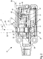
- Fig. 1 shows a sensor 11 according to the invention, the housing 13 of which is cut open in the longitudinal direction, in a perspective illustration.
- a transmitted light beam 19 is generated by means of the laser diode 15 and the lens 17, which is shown in FIG Fig. 2 is shown schematically as a dotted line.
- the transmitted light beam 19 runs through a transmitter tube 21 and then exits the sensor 11 through a front pane 23, which closes the housing 13 off from an outside space.
- the transmitting tube 21 divides the front panel 23 into a first section 25, which is arranged inside the transmitting tube 21 and through which the transmitting light beam 19 passes, and a second section 27 outside the transmitting tube 21.
- the transmitting tube 21 thus forms a separating element in the area of the front panel 23 29 between the first section 25 and the second section 27 of the front pane 23.
- the first section 25 of the front pane is arranged to be slightly inclined with respect to the second section 27.
- the surfaces of the first section 25 and the second section 27 enclose an angle 30 of approximately 1 degree.
- This arrangement of the first and second sections 25, 27 at the angle 30 prevents light from the transmitted light beam 19 from being reflected back on the front pane 23 in the direction of the laser diode 15. This avoids disturbance of the transmitted light beam 19 due to such reflections which could occur, for example, as a result of a further reflection of the light reflected back on shiny parts of the laser diode 15 and which could generate secondary light beams.
- back reflections could Influence the laser power, either directly within a laser crystal of the laser diode 15 or indirectly by striking a monitor diode (not shown), via which the laser power is controlled.
- the transmitted light beam 19 When the transmitted light beam 19 hits an object (not shown) outside the housing 13 of the sensor 11, the transmitted light beam 19 is reflected or remitted on this. A portion of this light reaches the front panel 23 of the sensor 11 via a reception path 31.
- the reception path 31 is shown in FIG Fig. 2 shown by way of example with the aid of two light beams 33.
- the light reflected or remitted on the object also passes along the receiving path 31 through the front pane 23 to a mirror 35, which represents a focusing element of the sensor 11.
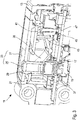
- the sensor 11 is characterized in that the mirror 35 is arranged in the area of the transmitting tube 21 and at least partially surrounds it. How to get in Fig. 1 and 3 can see, the mirror 35 also extends into areas in the viewing direction from Fig. 1 and 3 lie behind the transmission tube 21.
- the transmission light beam 19 and the reception path 31 are in the area in front of the mirror 35, ie in Fig. 1 and 3 above the mirror 35, aligned essentially parallel.
- the transmitted light beam 19 runs almost through the focal point of the mirror 35. Due to the parallel alignment of the receiving path 31 and the transmitted light beam 19, the mirror 35 has a large focal length, which is greater than in sensors from the prior art, which act as a focusing element Use lens.
- the transmission light beam 19 is completely optically isolated from the mirror 35 and further components of the sensor 11 by means of the transmission tube 21, which components are arranged along the reception path 31.
- a sealing element 37 is additionally arranged on the underside of the transmitter tube 21 for optical isolation.
- the sealing element 37 is used to connect the Transmission tube 21 with a carrier element 39 (cf. Fig. 2 ), in which the lens 17 is also housed.
- the sealing element 37 ensures tolerance compensation in the arrangement and alignment of the transmitting tube 21.
- the transmitting tube 21 forms the separating element 29 between the first and second sections 25, 27 of the front panel 23
- light of the transmitting light beam 19 is prevented from being reflected or scattered in the front panel 23 within the housing 13 of the sensor 11 into the receiving path 31 and in particular reaches the mirror 35.
- the separating element 29 extends over the entire cross section of the front pane 23, i.e. up to its outer surface. "Optical crosstalk" between the transmission light beam 19 and the reception path 31 is thus prevented by isolating the transmission light beam 19 by means of the transmission tube 21 and the sealing element 37 and in particular by the separating element 29 between the first and second sections 25, 27 of the front panel 23.
- the focal length of the mirror 35 can be selected such that an intermediate image is generated in a plane in which a diaphragm 41 is arranged.
- a bandpass filter 43 is arranged between the mirror 35 and the diaphragm 41, through which only light with a wavelength in a predetermined range that includes the wavelength of the light emitted by the laser diode 15 passes.
- the light detected by the mirror 35 falls on a light guide element 45, via which the light is finally guided to a detection element 47.
- the light guide element 45 is aligned almost parallel to the transmitted light beam 19.
- the detection element 47 has an array of single photon avalanche photodiodes, which is also referred to as a SPAD array (SPAD from "Single Photon Avalanche Diode”).
- SPAD array of the detection element 47 is illuminated in a certain area or light spot via the light guide element 45 with light that is detected by the mirror 35 and includes light of the transmitted light beam 19 that reflects or reflects on an object outside the housing 13 of the sensor 11 was remitted. Due to the parallel alignment of the transmission light beam 19 and the reception path 31, the position of the illuminated area or light spot on the detection element 47 changes only insignificantly when the distance between the sensor 11 and the object changes.
- the mirror 35 surrounds the transmission tube 21 and thus the transmission light beam 19 and thus the mirror 35 as a focusing element of the sensor 11 is arranged in the same spatial area below the front pane 23 as the transmission light beam 19, the angle between the transmitted light beam 19 and the light beams 33 is minimized, which arrive along the receiving path 31 after being reflected on the object again via the front pane 23 onto the mirror 35.
- the triangulation is minimized, which occurs as a disruptive effect in known sensors in which the transmitted light beam and a focusing element, such as a lens, are spaced apart and spatially separated in the form of a "double eye".
- the light reflected on the object always strikes the front pane of the sensor at a certain angle before it reaches the focusing element. Due to the triangulation effect, the light spot on the detection element, which is formed on the detection element by the focusing element, therefore shifts when the distance between the sensor and the object varies. Furthermore, interference effects can occur as a result of the triangulation, for example as a result of multiple scattering of light within the front pane. With the sensor 11 according to the invention, however, the effects associated with the triangulation are minimized due to the parallel alignment of the transmitted light beam 19 and the reception path 31.
- the in Fig. 1 and 2 The sensor 11 shown, the first and second sections 25, 27 of the front pane 23 and the transmitter tube 21 are initially separate parts before the sensor 11 is installed. However, these are already connected to one another by means of ultrasonic welding to form a pre-assembly before the assembly of the sensor 11, which is then connected to the other elements of the sensor 11 is mounted. From the in Fig. 1 and 2 The sensor 11 shown differs from that in FIG Fig. 3 The sensor 11 shown only in that the transmitter tube 21 is produced together with the first and second sections 25, 27 by means of a two-component injection molding process, before these elements 21, 25 and 27 are in turn connected as a pre-assembly to further components of the sensor 11. In this production of the pre-assembly by means of two-component injection molding, an inclined arrangement of the first section 25 of the front panel 23 with respect to the second section 27 at an angle 30 of approximately 1 degree is provided.
Landscapes
- Engineering & Computer Science (AREA)
- Physics & Mathematics (AREA)
- Computer Networks & Wireless Communication (AREA)
- General Physics & Mathematics (AREA)
- Radar, Positioning & Navigation (AREA)
- Remote Sensing (AREA)
- Electromagnetism (AREA)
- Optical Radar Systems And Details Thereof (AREA)
- Length Measuring Devices By Optical Means (AREA)
Claims (9)
- Capteur de mesure de distance (11) comportant
une source de lumière (15) pour générer un faisceau lumineux d'émission (19),
au moins un élément de focalisation (35) pour détecter la lumière du faisceau lumineux d'émission (19) réfléchie ou renvoyée d'un objet,
un élément de détection (47) pour détecter la lumière détectée par l'élément de focalisation (35), et
une unité d'évaluation (49) qui est réalisée pour déterminer le temps de parcours de la lumière entre la source de lumière (15) et l'élément de détection (47),
dans lequel
le faisceau lumineux d'émission (19) et un trajet de réception (31) de la lumière réfléchie ou renvoyée à détecter sont orientés de manière sensiblement parallèle l'un à l'autre devant l'élément de focalisation (35),
le capteur (11) comprend une vitre frontale (23) qui est traversée par le faisceau lumineux d'émission (19) et par la lumière réfléchie ou renvoyée à détecter,
la vitre frontale (23) comprend un élément de séparation (29) qui divise la vitre frontale (23) en une première portion (25) traversée par le faisceau lumineux d'émission (19) et en une seconde portion (27) traversée par la lumière réfléchie ou renvoyée à détecter, et
l'élément de séparation (29) s'étend dans la direction du faisceau lumineux d'émission (19) sur toute la section transversale de la vitre frontale (23), et une surface de la seconde portion (27) de la vitre frontale (23) est disposée à angle droit par rapport au faisceau lumineux d'émission (19), caractérisé en ce que
une surface de la première portion (25) est inclinée par rapport à la surface de la seconde portion (27) de la vitre frontale (23), et
l'élément de focalisation (35) est réalisé sous forme de miroir. - Capteur (11) selon la revendication 1,
caractérisé en ce que
le faisceau lumineux d'émission (19) est disposé coaxialement par rapport au trajet de réception (31) de la lumière réfléchie ou renvoyée à détecter devant l'élément de focalisation (35). - Capteur (11) selon la revendication 1 ou 2,
caractérisé en ce que
l'élément de séparation (29) est disposé tout autour du faisceau lumineux d'émission (19). - Capteur (11) selon l'une au moins des revendications précédentes,
caractérisé en ce que
la première et/ou la seconde portion (25, 27) de la vitre frontale (23) et/ou l'élément de séparation (29) sont des pièces séparées assemblées entre elles par soudage par ultrasons. - Capteur (11) selon l'une au moins des revendications précédentes,
caractérisé en ce que
les première et seconde portions (25, 27) de la vitre frontale (23) et l'élément de séparation (29) sont fabriqués par un procédé de coulée par injection. - Capteur (11) selon l'une au moins des revendications précédentes,
caractérisé en ce que
un élément de guidage de lumière (45) est disposé entre l'élément de focalisation (35) et l'élément de détection (47). - Capteur (11) selon l'une au moins des revendications précédentes,
caractérisé en ce que
un diaphragme (41) est disposé dans un plan dans lequel l'élément de focalisation (35) génère une image intermédiaire. - Capteur (11) selon l'une au moins des revendications précédentes,
caractérisé en ce que
l'élément de détection (47) comprend au moins une photodiode à avalanche. - Capteur (11) selon l'une au moins des revendications précédentes,
caractérisé en ce que
l'élément de détection (47) est réalisé sous la forme d'un champ de photodiodes à avalanche à photon unique (réseau SPAD).
Applications Claiming Priority (1)
| Application Number | Priority Date | Filing Date | Title |
|---|---|---|---|
| DE102018108631.8A DE102018108631A1 (de) | 2018-04-11 | 2018-04-11 | Entfernungsmessender Sensor |
Publications (2)
| Publication Number | Publication Date |
|---|---|
| EP3553564A1 EP3553564A1 (fr) | 2019-10-16 |
| EP3553564B1 true EP3553564B1 (fr) | 2021-05-12 |
Family
ID=65904055
Family Applications (1)
| Application Number | Title | Priority Date | Filing Date |
|---|---|---|---|
| EP19163963.2A Active EP3553564B1 (fr) | 2018-04-11 | 2019-03-20 | Capteur mesurant la distance |
Country Status (2)
| Country | Link |
|---|---|
| EP (1) | EP3553564B1 (fr) |
| DE (1) | DE102018108631A1 (fr) |
Families Citing this family (2)
| Publication number | Priority date | Publication date | Assignee | Title |
|---|---|---|---|---|
| EP4624085A1 (fr) | 2024-03-28 | 2025-10-01 | Sick Ag | Barrière lumineuse à l'intérieur d'une vitre frontale |
| DE202024105807U1 (de) * | 2024-10-09 | 2026-01-14 | Leuze Electronic Gmbh + Co. Kg | Optischer Sensor |
Citations (1)
| Publication number | Priority date | Publication date | Assignee | Title |
|---|---|---|---|---|
| DE102011119707A1 (de) * | 2011-11-29 | 2013-05-29 | Valeo Schalter Und Sensoren Gmbh | Optische Messvorrichtung |
Family Cites Families (11)
| Publication number | Priority date | Publication date | Assignee | Title |
|---|---|---|---|---|
| DE2946111C2 (de) * | 1979-11-15 | 1986-09-11 | Messerschmitt-Bölkow-Blohm GmbH, 8012 Ottobrunn | Optischer Körper für ein Cassegrain- oder cassegrain-ähnliches System |
| DE4412044A1 (de) * | 1994-04-08 | 1995-10-12 | Leuze Electronic Gmbh & Co | Optoelektronische Vorrichtung zum Erfassen von Gegenständen in einem Überwachungsbereich |
| DE102007019101B4 (de) * | 2007-04-23 | 2013-05-29 | Diehl Bgt Defence Gmbh & Co. Kg | Vorrichtung zur Erfassung einer Objektszene |
| US7894044B1 (en) * | 2008-03-11 | 2011-02-22 | Oceanit Laboratories, Inc. | Laser for coherent LIDAR |
| EP2375266B1 (fr) * | 2010-04-09 | 2012-05-16 | Sick AG | Capteur optoélectronique et procédé de sécurisation |
| DE102011000947A1 (de) * | 2011-02-25 | 2012-08-30 | Realeyes Gmbh | Flache 3D-Displayeinheit |
| DE102012106063A1 (de) * | 2012-07-06 | 2014-05-08 | Lisa Laser Products Ohg Fuhrberg & Teichmann | Resonatorlose Laservorrichtung mit einem optisch aktives Material aufweisenden Multimode-Lichtleiter |
| EP2645125B1 (fr) * | 2012-03-27 | 2017-05-10 | Sick AG | Laser scanner et procédé destiné à la détection d'objets dans une zone de surveillance |
| EP2708914A1 (fr) * | 2012-09-18 | 2014-03-19 | Sick Ag | Capteur optoélectronique et procédé de détection d'une carte de profondeur |
| US9116243B1 (en) * | 2013-09-20 | 2015-08-25 | Rockwell Collins, Inc. | High altitude ice particle detection method and system |
| DE102014114363A1 (de) * | 2014-10-02 | 2016-04-07 | Valeo Schalter Und Sensoren Gmbh | Fensterkappe für das Gehäuse einer abtastenden optoelektronischen Messvorrichtung und Gehäuse mit einer solchen |
-
2018
- 2018-04-11 DE DE102018108631.8A patent/DE102018108631A1/de not_active Withdrawn
-
2019
- 2019-03-20 EP EP19163963.2A patent/EP3553564B1/fr active Active
Patent Citations (1)
| Publication number | Priority date | Publication date | Assignee | Title |
|---|---|---|---|---|
| DE102011119707A1 (de) * | 2011-11-29 | 2013-05-29 | Valeo Schalter Und Sensoren Gmbh | Optische Messvorrichtung |
Also Published As
| Publication number | Publication date |
|---|---|
| EP3553564A1 (fr) | 2019-10-16 |
| DE102018108631A1 (de) | 2019-10-17 |
Similar Documents
| Publication | Publication Date | Title |
|---|---|---|
| EP2002208B1 (fr) | Dispositif de mesure optique de distances et son procédé de fonctionnement | |
| EP2124069B1 (fr) | Système LIDAR omnidirectionnel | |
| EP2936193B1 (fr) | Système optique de détection d'objets à mems et véhicule à moteur équipé d'un tel système de détection | |
| EP1405037B1 (fr) | Dispositif de mesure optique de distance sur une plage de mesure etendue | |
| DE10326848B4 (de) | Optischer Sensor | |
| EP1355128B1 (fr) | Alignement automatique d'un senseur | |
| DE102013012789A1 (de) | Abtastende optoelektronische Detektionseinrichtung und Kraftfahrzeug mit einer solchen Detektionseinrichtung | |
| EP2189815B1 (fr) | Dispositif optique et procédé destiné à sa surveillance | |
| EP3432023B1 (fr) | Procédé de fabrication d'un capteur optoélectronique | |
| EP3699638B1 (fr) | Capteur optoélectronique et procédé de détection d'un objet | |
| EP2002281A1 (fr) | Dispositif de mesure optique de distances | |
| DE202009012114U1 (de) | Optoelektronischer Scanner | |
| EP3583444B1 (fr) | Capteur lidar servant à détecter un objet | |
| DE102015217910A1 (de) | Lidarsensor mit optischem Filter | |
| DE202005018197U1 (de) | Laser-Entfernungsmessungsvorrichtung | |
| EP3078984B1 (fr) | Capteur optoelectronique et procede de detection d'objets dans une zone de surveillance | |
| DE10341548A1 (de) | Optoelektronische Erfassungseinrichtung | |
| EP1160718A2 (fr) | Appareil à balayage laser | |
| EP3583445A1 (fr) | Capteur lidar servant à détecter un objet | |
| EP3654056B1 (fr) | Capteur et procédé de détection d'objets | |
| EP1118874A2 (fr) | Dispositif de balayage optique | |
| EP3553564B1 (fr) | Capteur mesurant la distance | |
| DE10247136A1 (de) | Schutzvorrichtung zur Überwachung eines mit einem Bauteil zu bewegenden Schutzbereichs | |
| DE102010003544A1 (de) | 3D-TOF-Kamera | |
| DE202008011469U1 (de) | Optoelektronischer Sensor |
Legal Events
| Date | Code | Title | Description |
|---|---|---|---|
| PUAI | Public reference made under article 153(3) epc to a published international application that has entered the european phase |
Free format text: ORIGINAL CODE: 0009012 |
|
| STAA | Information on the status of an ep patent application or granted ep patent |
Free format text: STATUS: THE APPLICATION HAS BEEN PUBLISHED |
|
| AK | Designated contracting states |
Kind code of ref document: A1 Designated state(s): AL AT BE BG CH CY CZ DE DK EE ES FI FR GB GR HR HU IE IS IT LI LT LU LV MC MK MT NL NO PL PT RO RS SE SI SK SM TR |
|
| AX | Request for extension of the european patent |
Extension state: BA ME |
|
| RAP1 | Party data changed (applicant data changed or rights of an application transferred) |
Owner name: SICK AG |
|
| STAA | Information on the status of an ep patent application or granted ep patent |
Free format text: STATUS: REQUEST FOR EXAMINATION WAS MADE |
|
| 17P | Request for examination filed |
Effective date: 20200323 |
|
| RBV | Designated contracting states (corrected) |
Designated state(s): AL AT BE BG CH CY CZ DE DK EE ES FI FR GB GR HR HU IE IS IT LI LT LU LV MC MK MT NL NO PL PT RO RS SE SI SK SM TR |
|
| STAA | Information on the status of an ep patent application or granted ep patent |
Free format text: STATUS: EXAMINATION IS IN PROGRESS |
|
| 17Q | First examination report despatched |
Effective date: 20200625 |
|
| GRAP | Despatch of communication of intention to grant a patent |
Free format text: ORIGINAL CODE: EPIDOSNIGR1 |
|
| STAA | Information on the status of an ep patent application or granted ep patent |
Free format text: STATUS: GRANT OF PATENT IS INTENDED |
|
| INTG | Intention to grant announced |
Effective date: 20210115 |
|
| GRAS | Grant fee paid |
Free format text: ORIGINAL CODE: EPIDOSNIGR3 |
|
| GRAA | (expected) grant |
Free format text: ORIGINAL CODE: 0009210 |
|
| STAA | Information on the status of an ep patent application or granted ep patent |
Free format text: STATUS: THE PATENT HAS BEEN GRANTED |
|
| AK | Designated contracting states |
Kind code of ref document: B1 Designated state(s): AL AT BE BG CH CY CZ DE DK EE ES FI FR GB GR HR HU IE IS IT LI LT LU LV MC MK MT NL NO PL PT RO RS SE SI SK SM TR |
|
| REG | Reference to a national code |
Ref country code: GB Ref legal event code: FG4D Free format text: NOT ENGLISH |
|
| REG | Reference to a national code |
Ref country code: CH Ref legal event code: EP |
|
| REG | Reference to a national code |
Ref country code: DE Ref legal event code: R096 Ref document number: 502019001396 Country of ref document: DE |
|
| REG | Reference to a national code |
Ref country code: IE Ref legal event code: FG4D Free format text: LANGUAGE OF EP DOCUMENT: GERMAN |
|
| REG | Reference to a national code |
Ref country code: AT Ref legal event code: REF Ref document number: 1392543 Country of ref document: AT Kind code of ref document: T Effective date: 20210615 |
|
| REG | Reference to a national code |
Ref country code: LT Ref legal event code: MG9D |
|
| REG | Reference to a national code |
Ref country code: NL Ref legal event code: MP Effective date: 20210512 |
|
| PG25 | Lapsed in a contracting state [announced via postgrant information from national office to epo] |
Ref country code: FI Free format text: LAPSE BECAUSE OF FAILURE TO SUBMIT A TRANSLATION OF THE DESCRIPTION OR TO PAY THE FEE WITHIN THE PRESCRIBED TIME-LIMIT Effective date: 20210512 Ref country code: HR Free format text: LAPSE BECAUSE OF FAILURE TO SUBMIT A TRANSLATION OF THE DESCRIPTION OR TO PAY THE FEE WITHIN THE PRESCRIBED TIME-LIMIT Effective date: 20210512 Ref country code: LT Free format text: LAPSE BECAUSE OF FAILURE TO SUBMIT A TRANSLATION OF THE DESCRIPTION OR TO PAY THE FEE WITHIN THE PRESCRIBED TIME-LIMIT Effective date: 20210512 Ref country code: BG Free format text: LAPSE BECAUSE OF FAILURE TO SUBMIT A TRANSLATION OF THE DESCRIPTION OR TO PAY THE FEE WITHIN THE PRESCRIBED TIME-LIMIT Effective date: 20210812 |
|
| PG25 | Lapsed in a contracting state [announced via postgrant information from national office to epo] |
Ref country code: IS Free format text: LAPSE BECAUSE OF FAILURE TO SUBMIT A TRANSLATION OF THE DESCRIPTION OR TO PAY THE FEE WITHIN THE PRESCRIBED TIME-LIMIT Effective date: 20210912 Ref country code: GR Free format text: LAPSE BECAUSE OF FAILURE TO SUBMIT A TRANSLATION OF THE DESCRIPTION OR TO PAY THE FEE WITHIN THE PRESCRIBED TIME-LIMIT Effective date: 20210813 Ref country code: NO Free format text: LAPSE BECAUSE OF FAILURE TO SUBMIT A TRANSLATION OF THE DESCRIPTION OR TO PAY THE FEE WITHIN THE PRESCRIBED TIME-LIMIT Effective date: 20210812 Ref country code: PL Free format text: LAPSE BECAUSE OF FAILURE TO SUBMIT A TRANSLATION OF THE DESCRIPTION OR TO PAY THE FEE WITHIN THE PRESCRIBED TIME-LIMIT Effective date: 20210512 Ref country code: LV Free format text: LAPSE BECAUSE OF FAILURE TO SUBMIT A TRANSLATION OF THE DESCRIPTION OR TO PAY THE FEE WITHIN THE PRESCRIBED TIME-LIMIT Effective date: 20210512 Ref country code: SE Free format text: LAPSE BECAUSE OF FAILURE TO SUBMIT A TRANSLATION OF THE DESCRIPTION OR TO PAY THE FEE WITHIN THE PRESCRIBED TIME-LIMIT Effective date: 20210512 Ref country code: RS Free format text: LAPSE BECAUSE OF FAILURE TO SUBMIT A TRANSLATION OF THE DESCRIPTION OR TO PAY THE FEE WITHIN THE PRESCRIBED TIME-LIMIT Effective date: 20210512 Ref country code: PT Free format text: LAPSE BECAUSE OF FAILURE TO SUBMIT A TRANSLATION OF THE DESCRIPTION OR TO PAY THE FEE WITHIN THE PRESCRIBED TIME-LIMIT Effective date: 20210913 |
|
| PG25 | Lapsed in a contracting state [announced via postgrant information from national office to epo] |
Ref country code: NL Free format text: LAPSE BECAUSE OF FAILURE TO SUBMIT A TRANSLATION OF THE DESCRIPTION OR TO PAY THE FEE WITHIN THE PRESCRIBED TIME-LIMIT Effective date: 20210512 |
|
| PG25 | Lapsed in a contracting state [announced via postgrant information from national office to epo] |
Ref country code: SK Free format text: LAPSE BECAUSE OF FAILURE TO SUBMIT A TRANSLATION OF THE DESCRIPTION OR TO PAY THE FEE WITHIN THE PRESCRIBED TIME-LIMIT Effective date: 20210512 Ref country code: EE Free format text: LAPSE BECAUSE OF FAILURE TO SUBMIT A TRANSLATION OF THE DESCRIPTION OR TO PAY THE FEE WITHIN THE PRESCRIBED TIME-LIMIT Effective date: 20210512 Ref country code: ES Free format text: LAPSE BECAUSE OF FAILURE TO SUBMIT A TRANSLATION OF THE DESCRIPTION OR TO PAY THE FEE WITHIN THE PRESCRIBED TIME-LIMIT Effective date: 20210512 Ref country code: CZ Free format text: LAPSE BECAUSE OF FAILURE TO SUBMIT A TRANSLATION OF THE DESCRIPTION OR TO PAY THE FEE WITHIN THE PRESCRIBED TIME-LIMIT Effective date: 20210512 Ref country code: DK Free format text: LAPSE BECAUSE OF FAILURE TO SUBMIT A TRANSLATION OF THE DESCRIPTION OR TO PAY THE FEE WITHIN THE PRESCRIBED TIME-LIMIT Effective date: 20210512 Ref country code: SM Free format text: LAPSE BECAUSE OF FAILURE TO SUBMIT A TRANSLATION OF THE DESCRIPTION OR TO PAY THE FEE WITHIN THE PRESCRIBED TIME-LIMIT Effective date: 20210512 Ref country code: RO Free format text: LAPSE BECAUSE OF FAILURE TO SUBMIT A TRANSLATION OF THE DESCRIPTION OR TO PAY THE FEE WITHIN THE PRESCRIBED TIME-LIMIT Effective date: 20210512 |
|
| REG | Reference to a national code |
Ref country code: DE Ref legal event code: R097 Ref document number: 502019001396 Country of ref document: DE |
|
| PLBE | No opposition filed within time limit |
Free format text: ORIGINAL CODE: 0009261 |
|
| STAA | Information on the status of an ep patent application or granted ep patent |
Free format text: STATUS: NO OPPOSITION FILED WITHIN TIME LIMIT |
|
| 26N | No opposition filed |
Effective date: 20220215 |
|
| PG25 | Lapsed in a contracting state [announced via postgrant information from national office to epo] |
Ref country code: IS Free format text: LAPSE BECAUSE OF FAILURE TO SUBMIT A TRANSLATION OF THE DESCRIPTION OR TO PAY THE FEE WITHIN THE PRESCRIBED TIME-LIMIT Effective date: 20210912 Ref country code: AL Free format text: LAPSE BECAUSE OF FAILURE TO SUBMIT A TRANSLATION OF THE DESCRIPTION OR TO PAY THE FEE WITHIN THE PRESCRIBED TIME-LIMIT Effective date: 20210512 |
|
| PG25 | Lapsed in a contracting state [announced via postgrant information from national office to epo] |
Ref country code: MC Free format text: LAPSE BECAUSE OF FAILURE TO SUBMIT A TRANSLATION OF THE DESCRIPTION OR TO PAY THE FEE WITHIN THE PRESCRIBED TIME-LIMIT Effective date: 20210512 |
|
| REG | Reference to a national code |
Ref country code: CH Ref legal event code: PL |
|
| REG | Reference to a national code |
Ref country code: BE Ref legal event code: MM Effective date: 20220331 |
|
| PG25 | Lapsed in a contracting state [announced via postgrant information from national office to epo] |
Ref country code: LU Free format text: LAPSE BECAUSE OF NON-PAYMENT OF DUE FEES Effective date: 20220320 Ref country code: LI Free format text: LAPSE BECAUSE OF NON-PAYMENT OF DUE FEES Effective date: 20220331 Ref country code: IE Free format text: LAPSE BECAUSE OF NON-PAYMENT OF DUE FEES Effective date: 20220320 Ref country code: CH Free format text: LAPSE BECAUSE OF NON-PAYMENT OF DUE FEES Effective date: 20220331 |
|
| PG25 | Lapsed in a contracting state [announced via postgrant information from national office to epo] |
Ref country code: BE Free format text: LAPSE BECAUSE OF NON-PAYMENT OF DUE FEES Effective date: 20220331 |
|
| GBPC | Gb: european patent ceased through non-payment of renewal fee |
Effective date: 20230320 |
|
| PG25 | Lapsed in a contracting state [announced via postgrant information from national office to epo] |
Ref country code: GB Free format text: LAPSE BECAUSE OF NON-PAYMENT OF DUE FEES Effective date: 20230320 |
|
| PG25 | Lapsed in a contracting state [announced via postgrant information from national office to epo] |
Ref country code: GB Free format text: LAPSE BECAUSE OF NON-PAYMENT OF DUE FEES Effective date: 20230320 |
|
| PG25 | Lapsed in a contracting state [announced via postgrant information from national office to epo] |
Ref country code: MK Free format text: LAPSE BECAUSE OF FAILURE TO SUBMIT A TRANSLATION OF THE DESCRIPTION OR TO PAY THE FEE WITHIN THE PRESCRIBED TIME-LIMIT Effective date: 20210512 Ref country code: CY Free format text: LAPSE BECAUSE OF FAILURE TO SUBMIT A TRANSLATION OF THE DESCRIPTION OR TO PAY THE FEE WITHIN THE PRESCRIBED TIME-LIMIT Effective date: 20210512 |
|
| PG25 | Lapsed in a contracting state [announced via postgrant information from national office to epo] |
Ref country code: HU Free format text: LAPSE BECAUSE OF FAILURE TO SUBMIT A TRANSLATION OF THE DESCRIPTION OR TO PAY THE FEE WITHIN THE PRESCRIBED TIME-LIMIT; INVALID AB INITIO Effective date: 20190320 |
|
| PG25 | Lapsed in a contracting state [announced via postgrant information from national office to epo] |
Ref country code: MT Free format text: LAPSE BECAUSE OF FAILURE TO SUBMIT A TRANSLATION OF THE DESCRIPTION OR TO PAY THE FEE WITHIN THE PRESCRIBED TIME-LIMIT Effective date: 20210512 |
|
| PGFP | Annual fee paid to national office [announced via postgrant information from national office to epo] |
Ref country code: DE Payment date: 20250319 Year of fee payment: 7 |
|
| PGFP | Annual fee paid to national office [announced via postgrant information from national office to epo] |
Ref country code: AT Payment date: 20250319 Year of fee payment: 7 |
|
| PGFP | Annual fee paid to national office [announced via postgrant information from national office to epo] |
Ref country code: FR Payment date: 20250324 Year of fee payment: 7 |
|
| PGFP | Annual fee paid to national office [announced via postgrant information from national office to epo] |
Ref country code: IT Payment date: 20250331 Year of fee payment: 7 |
|
| PG25 | Lapsed in a contracting state [announced via postgrant information from national office to epo] |
Ref country code: TR Free format text: LAPSE BECAUSE OF FAILURE TO SUBMIT A TRANSLATION OF THE DESCRIPTION OR TO PAY THE FEE WITHIN THE PRESCRIBED TIME-LIMIT Effective date: 20210512 |