EP3553564B1 - Rangefinding sensor - Google Patents
Rangefinding sensor Download PDFInfo
- Publication number
- EP3553564B1 EP3553564B1 EP19163963.2A EP19163963A EP3553564B1 EP 3553564 B1 EP3553564 B1 EP 3553564B1 EP 19163963 A EP19163963 A EP 19163963A EP 3553564 B1 EP3553564 B1 EP 3553564B1
- Authority
- EP
- European Patent Office
- Prior art keywords
- sensor
- light beam
- light
- section
- reflected
- Prior art date
- Legal status (The legal status is an assumption and is not a legal conclusion. Google has not performed a legal analysis and makes no representation as to the accuracy of the status listed.)
- Active
Links
- 238000001514 detection method Methods 0.000 claims description 48
- 230000005540 biological transmission Effects 0.000 claims description 39
- 238000011156 evaluation Methods 0.000 claims description 7
- 238000001746 injection moulding Methods 0.000 claims description 6
- 238000000926 separation method Methods 0.000 claims description 6
- 238000003466 welding Methods 0.000 claims description 3
- 239000004020 conductor Substances 0.000 claims 1
- 238000005259 measurement Methods 0.000 description 14
- 230000000694 effects Effects 0.000 description 8
- 230000003287 optical effect Effects 0.000 description 6
- 238000007789 sealing Methods 0.000 description 5
- 230000010363 phase shift Effects 0.000 description 4
- 230000008859 change Effects 0.000 description 2
- 238000005516 engineering process Methods 0.000 description 2
- 238000009434 installation Methods 0.000 description 2
- 238000002955 isolation Methods 0.000 description 2
- 238000012634 optical imaging Methods 0.000 description 2
- 230000009467 reduction Effects 0.000 description 2
- 238000003491 array Methods 0.000 description 1
- 239000013078 crystal Substances 0.000 description 1
- 230000009849 deactivation Effects 0.000 description 1
- 238000006073 displacement reaction Methods 0.000 description 1
- 238000003384 imaging method Methods 0.000 description 1
- 230000006872 improvement Effects 0.000 description 1
- 230000002452 interceptive effect Effects 0.000 description 1
- 238000004519 manufacturing process Methods 0.000 description 1
- 239000013307 optical fiber Substances 0.000 description 1
- 230000009897 systematic effect Effects 0.000 description 1
Images

Classifications
-
- G—PHYSICS
- G01—MEASURING; TESTING
- G01S—RADIO DIRECTION-FINDING; RADIO NAVIGATION; DETERMINING DISTANCE OR VELOCITY BY USE OF RADIO WAVES; LOCATING OR PRESENCE-DETECTING BY USE OF THE REFLECTION OR RERADIATION OF RADIO WAVES; ANALOGOUS ARRANGEMENTS USING OTHER WAVES
- G01S17/00—Systems using the reflection or reradiation of electromagnetic waves other than radio waves, e.g. lidar systems
- G01S17/02—Systems using the reflection of electromagnetic waves other than radio waves
- G01S17/06—Systems determining position data of a target
- G01S17/42—Simultaneous measurement of distance and other co-ordinates
-
- G—PHYSICS
- G01—MEASURING; TESTING
- G01S—RADIO DIRECTION-FINDING; RADIO NAVIGATION; DETERMINING DISTANCE OR VELOCITY BY USE OF RADIO WAVES; LOCATING OR PRESENCE-DETECTING BY USE OF THE REFLECTION OR RERADIATION OF RADIO WAVES; ANALOGOUS ARRANGEMENTS USING OTHER WAVES
- G01S7/00—Details of systems according to groups G01S13/00, G01S15/00, G01S17/00
- G01S7/48—Details of systems according to groups G01S13/00, G01S15/00, G01S17/00 of systems according to group G01S17/00
- G01S7/481—Constructional features, e.g. arrangements of optical elements
- G01S7/4811—Constructional features, e.g. arrangements of optical elements common to transmitter and receiver
- G01S7/4812—Constructional features, e.g. arrangements of optical elements common to transmitter and receiver transmitted and received beams following a coaxial path
-
- G—PHYSICS
- G01—MEASURING; TESTING
- G01S—RADIO DIRECTION-FINDING; RADIO NAVIGATION; DETERMINING DISTANCE OR VELOCITY BY USE OF RADIO WAVES; LOCATING OR PRESENCE-DETECTING BY USE OF THE REFLECTION OR RERADIATION OF RADIO WAVES; ANALOGOUS ARRANGEMENTS USING OTHER WAVES
- G01S7/00—Details of systems according to groups G01S13/00, G01S15/00, G01S17/00
- G01S7/48—Details of systems according to groups G01S13/00, G01S15/00, G01S17/00 of systems according to group G01S17/00
- G01S7/481—Constructional features, e.g. arrangements of optical elements
- G01S7/4811—Constructional features, e.g. arrangements of optical elements common to transmitter and receiver
- G01S7/4813—Housing arrangements
Definitions
- the present invention relates to a distance measuring sensor which has a light source for generating a transmission light beam, at least one focusing element for detecting light of the transmission light beam reflected or remitted on an object and a detection element which is provided for detecting the light which is passed through the focusing element is captured.
- TOF sensor time-of-flight sensor
- the transit time of the light is determined, for example between the light source and the detection element, in order to use the transit time and the speed of light to determine the distance between the sensor and the Measure object on which the transmitted light beam is reflected or remitted.
- the transit time can be, for example, the transit time of a light pulse.
- the phase shift of a modulated signal is evaluated, which, however, also corresponds to an at least indirect determination of the light transit time. In this respect, such an evaluation of a phase shift is also subsumed under the term light transit time determination in the present text.
- Such TOF sensors are used, for example, for object recognition or in scanners, with a predetermined spatial area being scanned, for example, by means of a laser as the light source.
- the light source and the focusing element are each arranged in a separate transmitting area or receiving area, the light source and the focusing element being mutually exclusive and the transmitting light beam thus being optically isolated from the focusing element and the detection element within the sensor. Because of the spatial Separation of the transmitting and receiving areas, which is achieved, for example, with a separating web, such a sensor is also referred to as a sensor with "double eyes".
- the separating web usually only extends as far as a front pane of the sensor, which closes a housing of the sensor from the outside space.
- Both the transmitted light beam and a receiving path of the light that is to be detected by means of the focusing element thus run through the front pane.
- optical crosstalk between the transmitted light beam and the focusing element can occur via the front pane.
- the light of the transmitted light beam reaches the focusing element and thus the detection element of the sensor directly via the front pane, without having previously been reflected on an object outside the sensor.
- This crosstalk falsifies the measurement signal that is generated by the detection element and leads to systematic measurement errors.
- either the focusing element is arranged as far away from the transmitted light beam as possible in the direction of the front screen extension, or two separate front screens are provided for the sending and receiving areas of the sensor .
- a triangulation effect occurs, with two sides of the triangle being formed by the transmission light beam and the reception path between the object and the sensor and the third side of the triangle corresponding to the distance between the focal point of the focusing element and the transmission light beam.
- Such a triangulation causes a light spot, which by means of the focusing element by capturing and focusing the reflected from the object or remitted light is formed on the detection element, shifts within a certain range when the distance between the object and the sensor changes. Furthermore, due to the triangulation, ie due to the always existing angle of inclination between the normal to the windshield and the receiving path, multiple scattering can occur within the windshield, which represent a disruptive effect for the measurement signal of the sensor.
- the detection element comprises an array of receiving cells, which are arranged, for example, on a square surface, some of the cells only receive scattered light that was not reflected or remitted by the object as desired. This worsens the signal-to-noise ratio of the measurement signal generated by the detection element. Due to the displacement of the light spot, which is caused by the triangulation when the distance between the object and the sensor changes, it is also difficult to subsequently separate the measurement signal, which is created by the reflected or remitted light to be detected, from the signal. caused by the unwanted scattered light.
- the EP 2 645 125 A1 describes a distance measuring sensor having features according to related technology.
- the DE 10 2011 119 707 A1 describes an optical measuring device with a windshield, in which the surface of a first section of the windshield is inclined with respect to the surface of a second section of the windshield.
- One object of the invention is to further develop a sensor of the type mentioned at the beginning in such a way that the intensity of undesired light that enters the sensor in addition to the reflected or remitted light to be detected is minimized.
- a distance measuring sensor with the features of claim 1.
- a transmission light beam which is generated by means of a light source of the sensor, and a receiving path of light of the transmission light beam, which is reflected or remitted on an object and is detected by a focusing element of the sensor, are aligned essentially parallel to one another in front of the focusing element.
- the transmission light beam and the reception path of the light to be detected in front of the focusing element are preferably aligned completely parallel to one another.
- the sensor according to the invention further comprises a detection element for detecting the light detected by the focusing element and an evaluation unit which is designed to determine the transit time of the light between the light source and the detection element. On the basis of the determined transit time, the distance between the sensor and the object is also determined, as described above.
- the transit time can be, for example, the transit time of a light pulse.
- the phase shift of a modulated signal is evaluated, which, however, also corresponds to an at least indirect determination of the light transit time. In this respect, such an evaluation of a phase shift is also subsumed under the term light transit time determination in the present text.
- the above-described effects of triangulation can be minimized, that is to say the effects mentioned at the beginning that are caused by a Angle of inclination between the transmission light beam and the receiving path are caused.
- the lateral distance between the transmission light beam and a focal point of the focusing element is preferably as small as possible, so that the transmission light beam runs almost through the focal point or through a focal area of the focusing element.
- the focusing element preferably surrounds an area through which the transmitted light beam runs.
- the focusing element illuminates a light spot on the detection element, the position of which hardly changes when the distance between the sensor and an object on which the transmitted light beam is reflected or remitted varies .
- the detection element can be precisely arranged or adjusted at the end of the reception path, as a result of which the size of a measurement signal that is generated by the detection element is maximized and its signal-to-noise ratio is improved.
- the parallel alignment between the transmission light beam and the reception path enables a large focal length of the focusing element. This enlarges the scanning area in which a distance measurement by means of the sensor is possible. Due to the large focal length, an intermediate image can be generated in a plane between the focusing element and the detection element. The beam path between the focusing element and the detection element can be precisely defined by means of the intermediate image. As a result, the intensity of the light that reaches the detection element can in turn be optimized, so that the signal-to-noise ratio of the signal that is generated by the detection element is further improved.
- the detection element comprises, in particular, a field or array of receiving cells
- an active area or a “region of interest” can be placed on it (ROI) "because the position of the area or light spot illuminated by the focusing element on the detection element does not change due to the parallel alignment between the transmission light beam and the receiving path. Only those receiving cells of the detection element are activated that are actually in the area of the light spot , while those receiving cells are deactivated that are not reached by the reflected or remitted light of the transmitted light beam to be detected, but instead only pick up unwanted scattered light, which in turn improves the signal-to-noise ratio of the measurement signal from the sensor.
- An array of receiving elements forming the detection element can be made smaller than comparable arrays according to the prior art due to the precise and virtually unchanged position of the light point to be detected.
- the number of receiving elements to be read out is lower, so that a data reduction can be achieved.
- the receiving elements can be read out within a shorter period of time.
- the respectively active area within the array can be flexibly adapted to the changed reception path in the event of an exchange or a change of components within the reception path of the light to be detected.
- the sensor also has a front pane through which the transmitted light beam and the reflected or remitted light to be detected pass.
- the front pane has a separating element which divides the front pane into a first section, through which the transmitted light beam passes, and a second section, through which the reflected or remitted light to be detected passes. Furthermore, the separating element extends in the direction of the transmitted light beam over the entire cross section of the front pane.
- the reception path of the sensor in the area of the front pane is completely optically isolated from the transmitted light beam.
- the separating element consequently prevents part of the light from the transmitted light beam from reaching the focusing element directly via the front pane without being reflected or remitted as desired on an object.
- the intensity of undesired scattered light in the receiving path is in turn reduced, so that, conversely, the signal-to-noise ratio of the measurement signal is further improved.
- the surface of the second section of the front pane is arranged at right angles with respect to the transmitted light beam. Furthermore, the surface of the first section of the windshield is inclined with respect to the surface of the second section. An angle of inclination between the respective surfaces of the first or second section of the front pane preferably has a size of at most 5 degrees and particularly preferably a size of at most 1 degree.
- the inclination of the surface, in particular of the first section of the front pane can prevent light from the transmitted light beam from being reflected back into the light source on the front pane. This is particularly advantageous if the light source is designed as a laser, since an influencing of the laser power by such back reflection is excluded if the first section of the front pane is inclined.
- a monitor diode that may be present in such a laser is likewise not influenced by back reflection when the first section of the front pane is inclined.
- generation of secondary light rays due to further reflection on shiny parts within the light source is prevented.
- the focusing element is designed as a mirror, which is preferably a concave mirror.
- the mirror allows the receiving path of the light to be detected to be adapted to an installation space available within the sensor.
- the installation space within a housing of the sensor in the transverse direction to the transmitted light beam can be better utilized with a mirror than, for example, with a lens.
- a mirror allows the use of greater focal lengths of the focusing element compared to a lens, for example. Conversely, increasing the focal length reduces a field of vision within which the light reflected or remitted by the object is recorded. This in turn improves the signal-to-noise ratio of the measurement signal from the sensor.
- the transmitted light beam is preferably arranged in front of the focusing element coaxially with respect to the receiving path of the reflected or remitted light to be detected. Since the light that is diffusely reflected or remitted on the object is detected via the receiving path, the receiving path has a certain width, which is predetermined by the dimensions of the focusing element, in order to be able to detect a sufficient light intensity. In this embodiment of the invention, the transmitted light beam thus runs coaxially through the geometric center of the receiving path.
- the separating element is preferably arranged completely circumferentially around the transmitted light beam.
- the above-described optical isolation between the transmission light beam and the receiving path or the focusing path is achieved Element optimized.
- a completely circumferential separating element can be produced simply and inexpensively, for example in the form of a tube or tube.
- the first and / or the second section of the front panel and / or the separating element are separate parts which are connected to one another by ultrasonic welding, the front panel and the separating element advantageously being made of plastic.
- the first section of the front pane, the second section of the front pane and the separating element are preferably each separate parts. This enables the front panel and the separating element to be manufactured together as a pre-assembly, which can then be assembled within the sensor.
- the first and second sections of the front pane and the separating element can be produced by means of an injection molding process.
- the injection molding process is in particular a two-component injection molding process.
- a light guide element is arranged between the focusing element and the detection element.
- a light guide element causes an increase in the intensity of the light which reaches the detection element, since if a light guide is present, less light can be scattered out of the receiving path between the focusing element and the detection element.
- the optical imaging of the light to be detected can be precisely adjusted to a desired area of the detection element by means of the light guide element, which in turn can improve the quality of the measurement signal.
- a further improvement in the signal-to-noise ratio of the measurement signal from the sensor can be achieved in that a bandpass filter is advantageously arranged between the focusing element and the detection element.
- the bandpass filter preferably has a transmission range for light wavelengths which includes the wavelength of the light emitted by the light source. Unwanted scattered light with wavelengths outside the transmission range, on the other hand, can be absorbed by the bandpass filter and not contribute to the measurement signal of the sensor.
- a diaphragm is arranged in a plane in which the focusing element generates an intermediate image.
- the detection element preferably comprises at least one avalanche photodiode. Such a photodiode is particularly suitable for the detection of low light intensities.
- the detection element is preferably designed as an array of single photon avalanche photodiodes (SPAD array).
- SPAD array single photon avalanche photodiodes
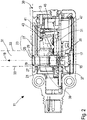
- Fig. 1 shows a sensor 11 according to the invention, the housing 13 of which is cut open in the longitudinal direction, in a perspective illustration.
- a transmitted light beam 19 is generated by means of the laser diode 15 and the lens 17, which is shown in FIG Fig. 2 is shown schematically as a dotted line.
- the transmitted light beam 19 runs through a transmitter tube 21 and then exits the sensor 11 through a front pane 23, which closes the housing 13 off from an outside space.
- the transmitting tube 21 divides the front panel 23 into a first section 25, which is arranged inside the transmitting tube 21 and through which the transmitting light beam 19 passes, and a second section 27 outside the transmitting tube 21.
- the transmitting tube 21 thus forms a separating element in the area of the front panel 23 29 between the first section 25 and the second section 27 of the front pane 23.
- the first section 25 of the front pane is arranged to be slightly inclined with respect to the second section 27.
- the surfaces of the first section 25 and the second section 27 enclose an angle 30 of approximately 1 degree.
- This arrangement of the first and second sections 25, 27 at the angle 30 prevents light from the transmitted light beam 19 from being reflected back on the front pane 23 in the direction of the laser diode 15. This avoids disturbance of the transmitted light beam 19 due to such reflections which could occur, for example, as a result of a further reflection of the light reflected back on shiny parts of the laser diode 15 and which could generate secondary light beams.
- back reflections could Influence the laser power, either directly within a laser crystal of the laser diode 15 or indirectly by striking a monitor diode (not shown), via which the laser power is controlled.
- the transmitted light beam 19 When the transmitted light beam 19 hits an object (not shown) outside the housing 13 of the sensor 11, the transmitted light beam 19 is reflected or remitted on this. A portion of this light reaches the front panel 23 of the sensor 11 via a reception path 31.
- the reception path 31 is shown in FIG Fig. 2 shown by way of example with the aid of two light beams 33.
- the light reflected or remitted on the object also passes along the receiving path 31 through the front pane 23 to a mirror 35, which represents a focusing element of the sensor 11.
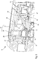
- the sensor 11 is characterized in that the mirror 35 is arranged in the area of the transmitting tube 21 and at least partially surrounds it. How to get in Fig. 1 and 3 can see, the mirror 35 also extends into areas in the viewing direction from Fig. 1 and 3 lie behind the transmission tube 21.
- the transmission light beam 19 and the reception path 31 are in the area in front of the mirror 35, ie in Fig. 1 and 3 above the mirror 35, aligned essentially parallel.
- the transmitted light beam 19 runs almost through the focal point of the mirror 35. Due to the parallel alignment of the receiving path 31 and the transmitted light beam 19, the mirror 35 has a large focal length, which is greater than in sensors from the prior art, which act as a focusing element Use lens.
- the transmission light beam 19 is completely optically isolated from the mirror 35 and further components of the sensor 11 by means of the transmission tube 21, which components are arranged along the reception path 31.
- a sealing element 37 is additionally arranged on the underside of the transmitter tube 21 for optical isolation.
- the sealing element 37 is used to connect the Transmission tube 21 with a carrier element 39 (cf. Fig. 2 ), in which the lens 17 is also housed.
- the sealing element 37 ensures tolerance compensation in the arrangement and alignment of the transmitting tube 21.
- the transmitting tube 21 forms the separating element 29 between the first and second sections 25, 27 of the front panel 23
- light of the transmitting light beam 19 is prevented from being reflected or scattered in the front panel 23 within the housing 13 of the sensor 11 into the receiving path 31 and in particular reaches the mirror 35.
- the separating element 29 extends over the entire cross section of the front pane 23, i.e. up to its outer surface. "Optical crosstalk" between the transmission light beam 19 and the reception path 31 is thus prevented by isolating the transmission light beam 19 by means of the transmission tube 21 and the sealing element 37 and in particular by the separating element 29 between the first and second sections 25, 27 of the front panel 23.
- the focal length of the mirror 35 can be selected such that an intermediate image is generated in a plane in which a diaphragm 41 is arranged.
- a bandpass filter 43 is arranged between the mirror 35 and the diaphragm 41, through which only light with a wavelength in a predetermined range that includes the wavelength of the light emitted by the laser diode 15 passes.
- the light detected by the mirror 35 falls on a light guide element 45, via which the light is finally guided to a detection element 47.
- the light guide element 45 is aligned almost parallel to the transmitted light beam 19.
- the detection element 47 has an array of single photon avalanche photodiodes, which is also referred to as a SPAD array (SPAD from "Single Photon Avalanche Diode”).
- SPAD array of the detection element 47 is illuminated in a certain area or light spot via the light guide element 45 with light that is detected by the mirror 35 and includes light of the transmitted light beam 19 that reflects or reflects on an object outside the housing 13 of the sensor 11 was remitted. Due to the parallel alignment of the transmission light beam 19 and the reception path 31, the position of the illuminated area or light spot on the detection element 47 changes only insignificantly when the distance between the sensor 11 and the object changes.
- the mirror 35 surrounds the transmission tube 21 and thus the transmission light beam 19 and thus the mirror 35 as a focusing element of the sensor 11 is arranged in the same spatial area below the front pane 23 as the transmission light beam 19, the angle between the transmitted light beam 19 and the light beams 33 is minimized, which arrive along the receiving path 31 after being reflected on the object again via the front pane 23 onto the mirror 35.
- the triangulation is minimized, which occurs as a disruptive effect in known sensors in which the transmitted light beam and a focusing element, such as a lens, are spaced apart and spatially separated in the form of a "double eye".
- the light reflected on the object always strikes the front pane of the sensor at a certain angle before it reaches the focusing element. Due to the triangulation effect, the light spot on the detection element, which is formed on the detection element by the focusing element, therefore shifts when the distance between the sensor and the object varies. Furthermore, interference effects can occur as a result of the triangulation, for example as a result of multiple scattering of light within the front pane. With the sensor 11 according to the invention, however, the effects associated with the triangulation are minimized due to the parallel alignment of the transmitted light beam 19 and the reception path 31.
- the in Fig. 1 and 2 The sensor 11 shown, the first and second sections 25, 27 of the front pane 23 and the transmitter tube 21 are initially separate parts before the sensor 11 is installed. However, these are already connected to one another by means of ultrasonic welding to form a pre-assembly before the assembly of the sensor 11, which is then connected to the other elements of the sensor 11 is mounted. From the in Fig. 1 and 2 The sensor 11 shown differs from that in FIG Fig. 3 The sensor 11 shown only in that the transmitter tube 21 is produced together with the first and second sections 25, 27 by means of a two-component injection molding process, before these elements 21, 25 and 27 are in turn connected as a pre-assembly to further components of the sensor 11. In this production of the pre-assembly by means of two-component injection molding, an inclined arrangement of the first section 25 of the front panel 23 with respect to the second section 27 at an angle 30 of approximately 1 degree is provided.
Description
Die vorliegende Erfindung betrifft einen entfernungsmessenden Sensor, der eine Lichtquelle zur Erzeugung eines Sendelichtstrahls, zumindest ein fokussierendes Element zum Erfassen von an einem Objekt reflektiertem oder remittiertem Licht des Sendelichtstrahls und ein Detektionselement aufweist, das zum Detektieren des Lichts vorgesehen ist, das durch das fokussierende Element erfasst wird.The present invention relates to a distance measuring sensor which has a light source for generating a transmission light beam, at least one focusing element for detecting light of the transmission light beam reflected or remitted on an object and a detection element which is provided for detecting the light which is passed through the focusing element is captured.
Eine Bauart solcher Sensoren ist ein sogenannter Time-Of-Flight-Sensor oder TOF-Sensor, bei dem die Laufzeit des Lichts ermittelt wird, beispielsweise zwischen der Lichtquelle und dem Detektionselement, um anhand der Laufzeit und der Lichtgeschwindigkeit die Entfernung zwischen dem Sensor und dem Objekt zu messen, an dem der Sendelichtstrahl reflektiert oder remittiert wird. Die Laufzeit kann zum Beispiel die Laufzeit eines Lichtpulses sein. Alternativ wird die Phasenverschiebung eines modulierten Signales ausgewertet, was aber ebenfalls einer zumindest indirekten Bestimmung der Lichtlaufzeit entspricht. Insofern wird auch eine solche Auswertung einer Phasenverschiebung im vorliegenden Text unter den Begriff Lichtlaufzeitbestimmung subsummiert. Solche TOF-Sensoren werden beispielsweise zur Objekterkennung oder in Scannern eingesetzt, wobei ein vorbestimmter Raumbereich beispielsweise mittels eines Lasers als Lichtquelle abgetastet wird.One type of such sensors is a so-called time-of-flight sensor or TOF sensor, in which the transit time of the light is determined, for example between the light source and the detection element, in order to use the transit time and the speed of light to determine the distance between the sensor and the Measure object on which the transmitted light beam is reflected or remitted. The transit time can be, for example, the transit time of a light pulse. Alternatively, the phase shift of a modulated signal is evaluated, which, however, also corresponds to an at least indirect determination of the light transit time. In this respect, such an evaluation of a phase shift is also subsumed under the term light transit time determination in the present text. Such TOF sensors are used, for example, for object recognition or in scanners, with a predetermined spatial area being scanned, for example, by means of a laser as the light source.
Bei bekannten TOF-Sensoren sind die Lichtquelle und das fokussierende Element jeweils in einem separaten Sendebereich bzw. Empfangsbereich angeordnet, wobei die Lichtquelle und das fokussierende Element voneinander bestandet sind und der Sendelichtstrahl somit von dem fokussierenden Element und dem Detektionselement innerhalb des Sensors optisch isoliert ist. Aufgrund der räumlichen Trennung des Sende- und Empfangsbereichs, die beispielsweise mit einem Trennsteg erreicht wird, wird ein solcher Sensor auch als ein Sensor mit "Doppelauge" bezeichnet.In known TOF sensors, the light source and the focusing element are each arranged in a separate transmitting area or receiving area, the light source and the focusing element being mutually exclusive and the transmitting light beam thus being optically isolated from the focusing element and the detection element within the sensor. Because of the spatial Separation of the transmitting and receiving areas, which is achieved, for example, with a separating web, such a sensor is also referred to as a sensor with "double eyes".
Bei solchen Sensoren erstreckt sich der Trennsteg in der Regel jedoch nur bis zu einer Frontscheibe des Sensors, die ein Gehäuse des Sensors gegenüber dem Außenraum abschließt. Durch die Frontscheibe verlaufen somit sowohl der Sendelichtstrahl als auch ein Empfangspfad des Lichts, das mittels des fokussierenden Elements erfasst werden soll. Insbesondere dann, wenn die räumliche Distanz zwischen dem Sendelichtstrahl und dem fokussierenden Element gering ist, kann es über die Frontscheibe zu einem optischen Übersprechen zwischen dem Sendelichtstrahl und dem fokussierenden Element kommen. Dabei gelangt Licht des Sendelichtstrahls direkt über die Frontscheibe zum fokussierenden Element und damit zum Detektionselement des Sensors, ohne dass es zuvor an einem Objekt außerhalb des Sensors reflektiert wurde. Dieses Übersprechen verfälscht das Messsignal, das mittels des Detektionselements generiert wird, und führt zu systematischen Messfehlern.In the case of such sensors, however, the separating web usually only extends as far as a front pane of the sensor, which closes a housing of the sensor from the outside space. Both the transmitted light beam and a receiving path of the light that is to be detected by means of the focusing element thus run through the front pane. In particular, if the spatial distance between the transmitted light beam and the focusing element is small, optical crosstalk between the transmitted light beam and the focusing element can occur via the front pane. In this case, the light of the transmitted light beam reaches the focusing element and thus the detection element of the sensor directly via the front pane, without having previously been reflected on an object outside the sensor. This crosstalk falsifies the measurement signal that is generated by the detection element and leads to systematic measurement errors.
Um das Übersprechen zwischen Licht aus dem Sendelichtstrahl und dem fokussierenden Element über die Frontscheibe zu verringern, ist entweder das fokussierende Element in Richtung der Frontscheibenerstreckung möglichst weit entfernt vom Sendelichtstrahl angeordnet, oder es sind zwei separate Frontscheiben für den Sende- und den Empfangsbereich des Sensors vorgesehen. In beiden Fällen tritt ein Triangulationseffekt auf, wobei zwei Seiten des Dreiecks durch den Sendelichtstrahl und den Empfangspfad zwischen dem Objekt und dem Sensor gebildet sind und die dritte Seite des Dreiecks dem Abstand zwischen dem Brennpunkt des fokussierenden Elements und dem Sendelichtstrahl entspricht.In order to reduce the crosstalk between the light from the transmitted light beam and the focusing element via the front screen, either the focusing element is arranged as far away from the transmitted light beam as possible in the direction of the front screen extension, or two separate front screens are provided for the sending and receiving areas of the sensor . In both cases, a triangulation effect occurs, with two sides of the triangle being formed by the transmission light beam and the reception path between the object and the sensor and the third side of the triangle corresponding to the distance between the focal point of the focusing element and the transmission light beam.
Eine solche Triangulation bewirkt, dass ein Lichtfleck, der mittels des fokussierenden Elements durch das Erfassen und Fokussieren des vom Objekt reflektierten oder remittierten Lichts auf dem Detektionselement gebildet wird, sich innerhalb eines gewissen Bereichs verschiebt, wenn sich die Entfernung zwischen Objekt und Sensor ändert. Ferner können durch die Triangulation, d.h. durch den stets vorhandenen Neigungswinkel zwischen der Normalen zur Frontscheibe und dem Empfangspfad, Mehrfachstreuungen innerhalb der Frontscheibe auftreten, die einen Störeffekt für das Messsignal des Sensors darstellen.Such a triangulation causes a light spot, which by means of the focusing element by capturing and focusing the reflected from the object or remitted light is formed on the detection element, shifts within a certain range when the distance between the object and the sensor changes. Furthermore, due to the triangulation, ie due to the always existing angle of inclination between the normal to the windshield and the receiving path, multiple scattering can occur within the windshield, which represent a disruptive effect for the measurement signal of the sensor.
Wenn das Detektionselement ein Feld von Empfangszellen umfasst, die beispielsweise auf einer quadratischen Fläche angeordnet sind, empfängt ein Teil der Zellen lediglich Streulicht, das nicht wie gewünscht vom Objekt reflektiert oder remittiert wurde. Dadurch verschlechtert sich das Signal-Rauschverhältnis des vom Detektionselement erzeugten Messsignals. Aufgrund der Verschiebung des Lichtflecks, die durch die Triangulation bei einer Veränderung des Abstands zwischen Objekt und Sensor bedingt ist, ist es ferner nur schwer möglich, das Messsignal, das durch das zu erfassende reflektierte oder remittierte Licht entsteht, nachträglich von dem Signal zu trennen, das durch das unerwünschte Streulicht hervorgerufen wird.If the detection element comprises an array of receiving cells, which are arranged, for example, on a square surface, some of the cells only receive scattered light that was not reflected or remitted by the object as desired. This worsens the signal-to-noise ratio of the measurement signal generated by the detection element. Due to the displacement of the light spot, which is caused by the triangulation when the distance between the object and the sensor changes, it is also difficult to subsequently separate the measurement signal, which is created by the reflected or remitted light to be detected, from the signal. caused by the unwanted scattered light.
Aus der
Die
In der
Die
Diese Aufgabe wird durch einen entfernungsmessenden Sensor mit den Merkmalen des Anspruchs 1 gelöst. Erfindungsgemäß sind ein Sendelichtstrahl, der mittels einer Lichtquelle des Sensors erzeugt wird, und ein Empfangspfad von Licht des Sendelichtstrahls, das an einem Objekt reflektiert oder remittiert wird und von einem fokussierenden Element des Sensors erfasst wird, vor dem fokussierenden Element im Wesentlichen parallel zueinander ausgerichtet. Der Sendelichtstrahl und der Empfangspfad des zu erfassenden Lichts vor dem fokussierenden Element sind vorzugsweise vollständig parallel zueinander ausgerichtet.This object is achieved by a distance measuring sensor with the features of claim 1. According to the invention, a transmission light beam, which is generated by means of a light source of the sensor, and a receiving path of light of the transmission light beam, which is reflected or remitted on an object and is detected by a focusing element of the sensor, are aligned essentially parallel to one another in front of the focusing element. The transmission light beam and the reception path of the light to be detected in front of the focusing element are preferably aligned completely parallel to one another.
Der erfindungsgemäße Sensor umfasst ferner ein Detektionselement zum Detektieren des durch das fokussierende Element erfassten Lichts und eine Auswerteeinheit, die ausgebildet ist, die Laufzeit des Lichts zwischen der Lichtquelle und dem Detektionselement zu ermitteln. Anhand der ermittelten Laufzeit erfolgt ferner die Bestimmung der Entfernung zwischen dem Sensor und dem Objekt, wie eingangs beschrieben wurde. Die Laufzeit kann zum Beispiel die Laufzeit eines Lichtpulses sein. Alternativ wird die Phasenverschiebung eines modulierten Signales ausgewertet, was aber ebenfalls einer zumindest indirekten Bestimmung der Lichtlaufzeit entspricht. Insofern wird auch eine solche Auswertung einer Phasenverschiebung im vorliegenden Text unter den Begriff Lichtlaufzeitbestimmung subsummiert.The sensor according to the invention further comprises a detection element for detecting the light detected by the focusing element and an evaluation unit which is designed to determine the transit time of the light between the light source and the detection element. On the basis of the determined transit time, the distance between the sensor and the object is also determined, as described above. The transit time can be, for example, the transit time of a light pulse. Alternatively, the phase shift of a modulated signal is evaluated, which, however, also corresponds to an at least indirect determination of the light transit time. In this respect, such an evaluation of a phase shift is also subsumed under the term light transit time determination in the present text.
Durch die parallele Ausrichtung des Empfangspfades des zu erfassenden Lichts mit dem Sendelichtstrahl lassen sich die vorstehend beschriebenen Auswirkungen der Triangulation minimieren, d.h. die eingangs genannten Effekte, die durch einen Neigungswinkel zwischen dem Sendelichtstrahl und dem Empfangspfad bedingt sind. Bei der parallelen Ausrichtung des Sendelichtstrahls und des Empfangspfades ist der laterale Abstand zwischen dem Sendelichtstrahl und einem Brennpunkt des fokussierenden Elements vorzugsweise möglichst gering, sodass der Sendelichtstrahl nahezu durch den Brennpunkt bzw. durch einen Fokusbereich des fokussierenden Elements verläuft. Ferner umgibt das fokussierende Element bevorzugt einen Bereich, durch den der Sendelichtstrahl verläuft.As a result of the parallel alignment of the receiving path of the light to be detected with the transmitted light beam, the above-described effects of triangulation can be minimized, that is to say the effects mentioned at the beginning that are caused by a Angle of inclination between the transmission light beam and the receiving path are caused. With the parallel alignment of the transmission light beam and the reception path, the lateral distance between the transmission light beam and a focal point of the focusing element is preferably as small as possible, so that the transmission light beam runs almost through the focal point or through a focal area of the focusing element. Furthermore, the focusing element preferably surrounds an area through which the transmitted light beam runs.
Aufgrund der parallelen Ausrichtung des Sendelichtstrahls und des Empfangspfades zu erfassenden Lichts leuchtet das fokussierende Element einen Lichtfleck auf dem Detektionselement aus, dessen Position sich nahezu nicht verändert, wenn der Abstand zwischen dem Sensor und einem Objekt variiert, an dem der Sendelichtstrahl reflektiert bzw. remittiert wird. Dadurch lässt sich das Detektionselement am Ende des Empfangspfades präzise anordnen bzw. justieren, wodurch die Größe eines Messsignals, das durch das Detektionselement erzeugt wird, maximiert und dessen Signal-Rauschverhältnis verbessert wird.Due to the parallel alignment of the transmitted light beam and the receiving path of the light to be detected, the focusing element illuminates a light spot on the detection element, the position of which hardly changes when the distance between the sensor and an object on which the transmitted light beam is reflected or remitted varies . As a result, the detection element can be precisely arranged or adjusted at the end of the reception path, as a result of which the size of a measurement signal that is generated by the detection element is maximized and its signal-to-noise ratio is improved.
Ferner ermöglicht die parallele Ausrichtung zwischen dem Sendelichtstrahl und dem Empfangspfad eine große Brennweite des fokussierenden Elements. Dadurch wird der Abtastbereich vergrößert, in welchem eine Entfernungsmessung mittels des Sensors möglich ist. Aufgrund der großen Brennweite kann ein Zwischenbild in einer Ebene zwischen dem fokussierenden Element und dem Detektionselement erzeugt werden. Mittels des Zwischenbildes lässt sich der Strahlengang zwischen dem fokussierenden Element und dem Detektionselement genau festlegen. Dadurch kann wiederum die Intensität des Lichts, welches das Detektionselement erreicht, optimiert werden, sodass das Signal-Rauschverhältnis des Signals, das durch das Detektionselement erzeugt wird, weiter verbessert wird.Furthermore, the parallel alignment between the transmission light beam and the reception path enables a large focal length of the focusing element. This enlarges the scanning area in which a distance measurement by means of the sensor is possible. Due to the large focal length, an intermediate image can be generated in a plane between the focusing element and the detection element. The beam path between the focusing element and the detection element can be precisely defined by means of the intermediate image. As a result, the intensity of the light that reaches the detection element can in turn be optimized, so that the signal-to-noise ratio of the signal that is generated by the detection element is further improved.
Wenn das Detektionselement insbesondere ein Feld bzw. Array von Empfangszellen umfasst, kann auf diesem ein aktiver Bereich bzw. eine "Region of Interest (ROI)" festgelegt werden, da sich die Position des durch das fokussierende Element ausgeleuchteten Bereichs oder Lichtflecks auf dem Detektionselement aufgrund der parallelen Ausrichtung zwischen Sendelichtstrahl und Empfangspfad nicht ändert. Dabei werden nur solche Empfangszellen des Detektionselements aktiviert, die tatsächlich im Bereich des Lichtflecks liegen, während solche Empfangszellen deaktiviert werden, die vom zu erfassenden reflektierten oder remittierten Licht des Sendelichtstrahls nicht erreicht werden, sondern stattdessen nur unerwünschtes Streulicht aufnehmen. Dadurch lässt sich wiederum das Signal-Rauschverhältnis des Messsignals des Sensors verbessern.If the detection element comprises, in particular, a field or array of receiving cells, an active area or a “region of interest” can be placed on it (ROI) "because the position of the area or light spot illuminated by the focusing element on the detection element does not change due to the parallel alignment between the transmission light beam and the receiving path. Only those receiving cells of the detection element are activated that are actually in the area of the light spot , while those receiving cells are deactivated that are not reached by the reflected or remitted light of the transmitted light beam to be detected, but instead only pick up unwanted scattered light, which in turn improves the signal-to-noise ratio of the measurement signal from the sensor.
Ein zum Beispiel das Detektionselement bildendes Array aus Empfangselementen kann aufgrund der präzisen und nahezu unveränderten Lage des zu detektierenden Lichtpunktes kleiner ausgestaltet sein als vergleichbare Arrays gemäß dem Stand der Technik. Die Anzahl der auszulesenden Empfangselemente ist geringer, wodurch eine Datenreduktion erreicht werden kann. Ferner können die Empfangselemente aufgrund der verringerten Anzahl innerhalb einer kürzeren Zeitspanne ausgelesen werden. Darüber hinaus kann der jeweils aktive Bereich innerhalb des Arrays bei einem Austausch oder einer Veränderung von Komponenten innerhalb des Empfangspfades des zu erfassenden Lichts flexibel an den veränderten Empfangspfad angepasst werden.An array of receiving elements forming the detection element, for example, can be made smaller than comparable arrays according to the prior art due to the precise and virtually unchanged position of the light point to be detected. The number of receiving elements to be read out is lower, so that a data reduction can be achieved. Furthermore, because of the reduced number, the receiving elements can be read out within a shorter period of time. In addition, the respectively active area within the array can be flexibly adapted to the changed reception path in the event of an exchange or a change of components within the reception path of the light to be detected.
Der Sensor weist ferner eine Frontscheibe auf, durch die der Sendelichtstrahl und das zu erfassende reflektierte oder remittierte Licht hindurchtreten. Die Frontscheibe weist dabei ein Trennelement auf, das die Frontscheibe in einen ersten Abschnitt, durch den der Sendelichtstrahl hindurchtritt, und einen zweiten Abschnitt aufteilt, durch den das zu erfassende reflektierte oder remittierte Licht hindurchtritt. Ferner erstreckt sich das Trennelement in Richtung des Sendelichtstrahls über den gesamten Querschnitt der Frontscheibe.The sensor also has a front pane through which the transmitted light beam and the reflected or remitted light to be detected pass. The front pane has a separating element which divides the front pane into a first section, through which the transmitted light beam passes, and a second section, through which the reflected or remitted light to be detected passes. Furthermore, the separating element extends in the direction of the transmitted light beam over the entire cross section of the front pane.
Mittels des Trennelements wird der Empfangspfad des Sensors im Bereich der Frontscheibe gegenüber dem Sendelichtstrahl vollständig optisch isoliert. Dadurch kann das eingangs beschriebene optische Übersprechen von Licht des Sendelichtstrahls über die Frontscheibe in den Empfangspfad hinein verhindert werden. Das Trennelement verhindert folglich, dass ein Teil des Lichts aus dem Sendelichtstrahl über die Frontscheibe direkt auf das fokussierende Element gelangt, ohne wie gewünscht an einem Objekt reflektiert oder remittiert zu werden. Durch die Vermeidung des Übersprechens wird somit wiederum die Intensität von unerwünschtem Streulicht im Empfangspfad verringert, sodass umgekehrt das Signal-Rauschverhältnis des Messsignals weiter verbessert wird.By means of the separating element, the reception path of the sensor in the area of the front pane is completely optically isolated from the transmitted light beam. As a result, the initially described optical crosstalk of light from the transmitted light beam via the front pane into the reception path can be prevented. The separating element consequently prevents part of the light from the transmitted light beam from reaching the focusing element directly via the front pane without being reflected or remitted as desired on an object. By avoiding crosstalk, the intensity of undesired scattered light in the receiving path is in turn reduced, so that, conversely, the signal-to-noise ratio of the measurement signal is further improved.
Die Oberfläche des zweiten Abschnitts der Frontscheibe ist rechtwinklig bezüglich des Sendelichtstrahls angeordnet. Ferner ist die Oberfläche des ersten Abschnitts der Frontscheibe bezüglich der Oberfläche des zweiten Abschnitts geneigt. Dabei weist ein Neigungswinkel zwischen den jeweiligen Oberflächen des ersten bzw. zweiten Abschnitts der Frontscheibe bevorzugt eine Größe von höchstens 5 Grad und besonders bevorzugt eine Größe von höchstens 1 Grad auf.The surface of the second section of the front pane is arranged at right angles with respect to the transmitted light beam. Furthermore, the surface of the first section of the windshield is inclined with respect to the surface of the second section. An angle of inclination between the respective surfaces of the first or second section of the front pane preferably has a size of at most 5 degrees and particularly preferably a size of at most 1 degree.
Durch die Neigung der Oberfläche insbesondere des ersten Abschnitts der Frontscheibe kann eine Reflexion von Licht aus dem Sendelichtstrahl an der Frontscheibe zurück in die Lichtquelle hinein verhindert werden. Dies ist insbesondere vorteilhaft, wenn die Lichtquelle als Laser ausgebildet ist, da eine Beeinflussung der Laserleistung durch eine solche Rückreflexion ausgeschlossen ist, wenn der erste Abschnitt der Frontscheibe geneigt angeordnet ist. Außerdem wird eine möglicherweise vorhandene Monitordiode in einem solchen Laser bei einer Neigung des ersten Abschnitts der Frontscheibe ebenfalls nicht durch eine Rückreflexion beeinflusst. Zusätzlich wird eine Erzeugung von Nebenlichtstrahlen aufgrund einer weiteren Reflexion an glänzenden Teilen innerhalb der Lichtquelle verhindert.The inclination of the surface, in particular of the first section of the front pane, can prevent light from the transmitted light beam from being reflected back into the light source on the front pane. This is particularly advantageous if the light source is designed as a laser, since an influencing of the laser power by such back reflection is excluded if the first section of the front pane is inclined. In addition, a monitor diode that may be present in such a laser is likewise not influenced by back reflection when the first section of the front pane is inclined. In addition, generation of secondary light rays due to further reflection on shiny parts within the light source is prevented.
Außerdem ist das fokussierende Element ist als Spiegel ausgebildet, bei dem es sich bevorzugt um einen konkaven Spiegel handelt. Der Spiegel gestattet eine Anpassung des Empfangspfades des zu erfassenden Lichts an einen innerhalb des Sensors vorhandenen Bauraum. Insbesondere kann der Bauraum innerhalb eines Gehäuses des Sensors in Querrichtung zum Sendelichtstrahl mit einem Spiegel besser ausgenutzt werden als z.B. mit einer Linse.In addition, the focusing element is designed as a mirror, which is preferably a concave mirror. The mirror allows the receiving path of the light to be detected to be adapted to an installation space available within the sensor. In particular, the installation space within a housing of the sensor in the transverse direction to the transmitted light beam can be better utilized with a mirror than, for example, with a lens.
Die Verwendung eines Spiegels gestattet beispielsweise im Vergleich zu einer Linse die Verwendung größerer Brennweiten des fokussierenden Elements. Die Vergrößerung der Brennweite verkleinert umgekehrt einen Sichtbereich, innerhalb dessen das am Objekt reflektierte oder remittierte Licht erfasst wird. Dadurch wird wiederum das Signal-Rauschverhältnis des Messsignals des Sensors verbessert. Vorteilhafte Ausführungsformen der Erfindung sind in den Unteransprüchen, der Beschreibung und in den Figuren angegeben.The use of a mirror allows the use of greater focal lengths of the focusing element compared to a lens, for example. Conversely, increasing the focal length reduces a field of vision within which the light reflected or remitted by the object is recorded. This in turn improves the signal-to-noise ratio of the measurement signal from the sensor. Advantageous embodiments of the invention are specified in the subclaims, the description and in the figures.
Vorzugsweise ist der Sendelichtstrahl koaxial bezüglich des Empfangspfades des zu erfassenden reflektierten oder remittierten Lichts vor dem fokussierenden Element angeordnet. Da über den Empfangspfad das Licht erfasst wird, das am Objekt diffus reflektiert oder remittiert wird, weist der Empfangspfad eine gewisse Breite auf, die durch die Abmessungen des fokussierenden Elements vorgegeben ist, um eine ausreichende Lichtintensität erfassen zu können. Bei dieser Ausführungsform der Erfindung verläuft der Sendelichtstrahl somit koaxial durch die geometrische Mitte des Empfangspfades. Durch eine solche Anordnung lassen sich die vorstehend beschriebenen Vorteile bezüglich der optischen Abbildung und des Signal-Rauschverhältnisses weiter verstärken.The transmitted light beam is preferably arranged in front of the focusing element coaxially with respect to the receiving path of the reflected or remitted light to be detected. Since the light that is diffusely reflected or remitted on the object is detected via the receiving path, the receiving path has a certain width, which is predetermined by the dimensions of the focusing element, in order to be able to detect a sufficient light intensity. In this embodiment of the invention, the transmitted light beam thus runs coaxially through the geometric center of the receiving path. The advantages described above with regard to optical imaging and the signal-to-noise ratio can be further enhanced by such an arrangement.
Das Trennelement ist vorzugweise vollständig umlaufend um den Sendelichtstrahl herum angeordnet. Dadurch wird die vorstehend beschriebene optische Isolierung zwischen dem Sendelichtstrahl und dem Empfangspfad bzw. dem fokussierenden Element optimiert. Außerdem lässt sich ein vollständig umlaufendes Trennelement einfach und kostengünstig herstellen, und zwar beispielsweise in der Form eines Rohres oder Tubus.The separating element is preferably arranged completely circumferentially around the transmitted light beam. As a result, the above-described optical isolation between the transmission light beam and the receiving path or the focusing path is achieved Element optimized. In addition, a completely circumferential separating element can be produced simply and inexpensively, for example in the form of a tube or tube.
Gemäß einer weiteren Ausführungsform der Erfindung sind der erste und/oder der zweite Abschnitt der Frontscheibe und/oder das Trennelement separate Teile, die durch Ultraschallschweißen miteinander verbunden sind, wobei die Frontscheibe und das Trennelement vorteilhafterweise aus Kunststoff hergestellt sind. Bevorzugt sind der erste Abschnitt der Frontscheibe, der zweite Abschnitt der Frontscheibe und das Trennelement jeweils separate Teile. Dies ermöglicht die gemeinsame Herstellung der Frontscheibe und des Trennelements als eine Vorbaugruppe, die anschließend innerhalb des Sensors montiert werden kann. Alternativ können der erste und zweite Abschnitt der Frontscheibe sowie das Trennelement mittels eines Spritzgussverfahrens hergestellt werden. Das Spritzgussverfahren ist dabei insbesondere ein Zwei-Komponenten-Spritzgussverfahren.According to a further embodiment of the invention, the first and / or the second section of the front panel and / or the separating element are separate parts which are connected to one another by ultrasonic welding, the front panel and the separating element advantageously being made of plastic. The first section of the front pane, the second section of the front pane and the separating element are preferably each separate parts. This enables the front panel and the separating element to be manufactured together as a pre-assembly, which can then be assembled within the sensor. Alternatively, the first and second sections of the front pane and the separating element can be produced by means of an injection molding process. The injection molding process is in particular a two-component injection molding process.
Gemäß einer weiteren Ausführungsform der Erfindung ist ein Lichtleiterelement zwischen dem fokussierenden Element und dem Detektionselement angeordnet. Ein solches Lichtleiterelement bewirkt eine Erhöhung der Intensität des Lichts, welches das Detektionselement erreicht, da bei Vorhandensein eines Lichtleiters weniger Licht aus dem Empfangspfad zwischen dem fokussierenden Element und dem Detektionselement herausgestreut werden kann. Darüber hinaus lässt sich die optische Abbildung des zu erfassenden Lichts auf einen gewünschten Bereich des Detektionselements mittels des Lichtleiterelements präzise einstellen, wodurch wiederum die Qualität des Messsignals verbessert werden kann.According to a further embodiment of the invention, a light guide element is arranged between the focusing element and the detection element. Such a light guide element causes an increase in the intensity of the light which reaches the detection element, since if a light guide is present, less light can be scattered out of the receiving path between the focusing element and the detection element. In addition, the optical imaging of the light to be detected can be precisely adjusted to a desired area of the detection element by means of the light guide element, which in turn can improve the quality of the measurement signal.
Eine weitere Verbesserung des Signal-Rauschverhältnis des Messsignals des Sensors lässt sich dadurch erreichen, dass vorteilhafterweise zwischen dem fokussierenden Element und dem Detektionselement ein Bandpassfilter angeordnet ist. Das Bandpassfilter weist bevorzugt einen Transmissionsbereich für Lichtwellenlängen auf, der die Wellenlänge des von der Lichtquelle emittierten Lichts umfasst. Unerwünschtes Streulicht mit Wellenlängen außerhalb des Transmissionsbereichs kann hingegen durch das Bandpassfilter absorbiert werden und nicht zum Messsignal des Sensors beitragen.A further improvement in the signal-to-noise ratio of the measurement signal from the sensor can be achieved in that a bandpass filter is advantageously arranged between the focusing element and the detection element. The bandpass filter preferably has a transmission range for light wavelengths which includes the wavelength of the light emitted by the light source. Unwanted scattered light with wavelengths outside the transmission range, on the other hand, can be absorbed by the bandpass filter and not contribute to the measurement signal of the sensor.
Gemäß einer weiteren Ausführungsform der Erfindung ist eine Blende in einer Ebene angeordnet, in der das fokussierende Element ein Zwischenbild erzeugt. Mittels einer solchen Blende wird die Abbildung des zu erfassenden Lichts auf das Detektionselement weiter verbessert, da unerwünschtes Streulicht in der Ebene des Zwischenbildes an einer geeigneten Stelle ausgeblendet wird, an welcher der Empfangspfad für das zu erfassende Licht aufgrund der Fokussierung zum Zwischenbild minimale Abmessungen aufweist.According to a further embodiment of the invention, a diaphragm is arranged in a plane in which the focusing element generates an intermediate image. By means of such a diaphragm, the imaging of the light to be detected on the detection element is further improved, since undesired scattered light is in the plane of the intermediate image is masked out at a suitable point at which the receiving path for the light to be detected has minimal dimensions due to the focus on the intermediate image.
Das Detektionselement umfasst bevorzugt zumindest eine Avalanchephotodiode. Eine solche Photodiode ist zur Detektion geringer Lichtintensitäten besonders geeignet. Das Detektionselement ist dabei bevorzugt als ein Feld aus Einzelphotonen-Avalanchephotodioden (SPAD-Array) ausgebildet. Wie vorstehend erläutert wurde, ändert sich aufgrund der erfindungsgemäßen parallelen Ausrichtung des Sendelichtstrahls und des Empfangspfades die Position des ausgeleuchteten Bereichs bzw. Lichtflecks auf dem Detektionselement nur unwesentlich, wenn sich der Abstand zwischen dem Sensor und dem Objekt verändert. Dies ermöglicht den Einsatz des SPAD-Arrays mit hochempfindlichen Dioden und die Verringerung der Intensität den Sendelichtstrahls, da der ausgeleuchtete Bereich auf dem SPAD-Array eindeutig lokalisiert werden kann und bevorzugt nur diejenigen Dioden des SPAD-Arrays aktiviert werden, die innerhalb des ausgeleuchteten Bereichs bzw. Lichtflecks liegen. Mögliche Störsignale solcher Dioden des SPAD-Arrays, die sich außerhalb des Lichtflecks befinden, können hingegen durch geeignete Deaktivierung von Dioden unterdrückt werden.The detection element preferably comprises at least one avalanche photodiode. Such a photodiode is particularly suitable for the detection of low light intensities. The detection element is preferably designed as an array of single photon avalanche photodiodes (SPAD array). As explained above, due to the parallel alignment of the transmission light beam and the receiving path according to the invention, the position of the illuminated area or light spot on the detection element changes only insignificantly when the distance between the sensor and the object changes. This enables the use of the SPAD array with highly sensitive diodes and the reduction of the intensity of the transmitted light beam, since the illuminated area on the SPAD array can be clearly localized and only those diodes of the SPAD array are activated that are within the illuminated area or within the illuminated area . Light spots lie. Possible interfering signals from such diodes of the SPAD array that are located outside the light spot, on the other hand, can be suppressed by suitable deactivation of diodes.
Die Erfindung wird nachfolgend rein beispielhaft anhand möglicher Ausführungsformen der Erfindung unter Bezugnahme auf die beigefügten Figuren erläutert. Es zeigen:
- Fig. 1
- eine perspektivische Schnittansicht eines erfindungsgemäßen Sensors,
- Fig. 2
- eine Schnittansicht des Sensors von
Fig. 1 und - Fig. 3
- einen Ausschnitt einer perspektivischen Schnittansicht des erfindungsgemäßen Sensors gemäß einer alternativen Ausführungsform.
- Fig. 1
- a perspective sectional view of a sensor according to the invention,
- Fig. 2
- a sectional view of the sensor of
Fig. 1 and - Fig. 3
- a detail of a perspective sectional view of the sensor according to the invention according to an alternative embodiment.
Oberhalb der Linse 17 verläuft der Sendelichtstrahl 19 durch ein Senderohr 21 und tritt anschließend durch eine Frontscheibe 23 aus dem Sensor 11 aus, welche das Gehäuse 13 gegenüber einem Außenraum abschließt. Das Senderohr 21 teilt die Frontscheibe 23 in einen ersten Abschnitt 25, der innerhalb des Senderohrs 21 angeordnet ist und durch den der Sendelichtstrahl 19 hindurchtritt, und einen zweiten Abschnitt 27 außerhalb des Senderohrs 21. Das Senderohr 21 bildet somit im Bereich der Frontscheibe 23 ein Trennelement 29 zwischen dem ersten Abschnitt 25 und dem zweiten Abschnitt 27 der Frontscheibe 23.Above the
Wie am besten in
Wenn der Sendelichtstrahl 19 außerhalb des Gehäuses 13 des Sensors 11 auf ein Objekt (nicht gezeigt) trifft, wird der Sendelichtstrahl 19 an diesem reflektiert oder remittiert. Ein Teil dieses Lichts gelangt über einen Empfangspfad 31 zurück zur Frontscheibe 23 des Sensors 11. Der Empfangspfad 31 ist in
Durch diese Anordnung des Spiegels 35 sind der Sendelichtstrahl 19 und der Empfangspfad 31 im Bereich vor dem Spiegel 35, d.h. in
Innerhalb des Gehäuses 13 ist der Sendelichtstrahl 19 mittels des Senderohrs 21 vollständig gegenüber dem Spiegel 35 und weiteren Komponenten des Sensors 11 optisch isoliert, die entlang des Empfangspfades 31 angeordnet sind. An der Unterseite des Senderohrs 21 ist zur optischen Isolierung zusätzlich ein Dichtelement 37 angeordnet. Außerdem dient das Dichtelement 37 zur Verbindung des Senderohrs 21 mit einem Trägerelement 39 (vgl.
Da das Senderohr 21 das Trennelement 29 zwischen dem ersten und zweiten Abschnitt 25, 27 der Frontscheibe 23 bildet, wird verhindert, dass Licht des Sendelichtstrahls 19 durch eine Reflexion oder Streuung in der Frontscheibe 23 innerhalb des Gehäuses 13 des Sensors 11 in den Empfangspfad 31 und insbesondere auf den Spiegel 35 gelangt. Das Trennelement 29 erstreckt sich zu diesem Zweck über den gesamten Querschnitt der Frontscheibe 23, d.h. bis zu dessen Außenfläche. Ein "optisches Übersprechen" zwischen dem Sendelichtstrahl 19 und dem Empfangspfad 31 wird somit durch die Isolierung des Sendelichtstrahls 19 mittels des Senderohrs 21 und des Dichtelements 37 und insbesondere durch das Trennelement 29 zwischen dem ersten und zweiten Abschnitt 25, 27 der Frontscheibe 23 verhindert.Since the transmitting
Aufgrund der parallelen Ausrichtung des Empfangspfades 31 mit dem Sendelichtstrahl 19 kann die Brennweite des Spiegels 35 derart ausgewählt werden, dass ein Zwischenbild in einer Ebene erzeugt wird, in der eine Blende 41 angeordnet ist. Durch die Beschränkung des Empfangspfades 31 mittels der Blende 41 wird unerwünschtes Streulicht ausgeblendet, das beispielsweise durch Mehrfachreflexionen innerhalb des Gehäuses 13 entsteht. Zwischen dem Spiegel 35 und der Blende 41 ist ferner ein Bandpassfilter 43 angeordnet, durch welches nur Licht mit einer Wellenlänge in einem vorbestimmten Bereich hindurchtritt, der die Wellenlänge des von der Laserdiode 15 emittierten Lichts umfasst. Hinter der Blende 41 fällt das von dem Spiegel 35 erfasste Licht auf ein Lichtleiterelement 45, über welches das Licht schließlich auf ein Detektionselement 47 geleitet wird. Das Lichtleiterelement 45 ist nahezu parallel zum Sendelichtstrahl 19 ausgerichtet.Due to the parallel alignment of the receiving
Eine Auswerteeinheit 49 des Sensors 11, die in
Das Detektionselement 47 weist ein Feld von Einzelphotonen-Avalanchephotodioden auf, das auch als SPAD-Array bezeichnet wird (SPAD vom engl. "Single Photon Avalanche Diode"). Das SPAD-Array des Detektionselements 47 wird in einem bestimmten Bereich bzw. Lichtfleck über das Lichtleiterelement 45 mit Licht ausgeleuchtet, das mittels des Spiegels 35 erfasst wird und Licht des Sendelichtstrahls 19 umfasst, das an einem Objekt außerhalb des Gehäuses 13 des Sensors 11 reflektiert oder remittiert wurde. Aufgrund der parallelen Ausrichtung des Sendelichtstrahls 19 und des Empfangspfades 31 ändert sich dabei die Position des ausgeleuchteten Bereichs bzw. Lichtflecks auf dem Detektionselement 47 nur unwesentlich, wenn sich der Abstand zwischen dem Sensor 11 und dem Objekt verändert. Dadurch ist es möglich, dass zum Detektieren des Lichts mittels des Detektionselements 47 nur diejenigen Dioden des SPAD-Arrays aktiviert werden, die innerhalb des ausgeleuchteten Bereichs bzw. Lichtflecks liegen. Da die übrigen Dioden des SPAD-Arrays, die sich außerhalb des Lichtflecks befinden und daher lediglich unerwünschtes Streulicht erfassen würden, deaktiviert werden können, lässt sich das Signal-Rauschverhältnis eines Messsignals verbessern, das durch das Detektionselement 47 erzeugt wird.The
Da der Spiegel 35 das Senderohr 21 und damit den Sendelichtstrahl 19 umgibt und somit der Spiegel 35 als fokussierendes Element des Sensors 11 im selben Raumbereich unterhalb der Frontscheibe 23 angeordnet ist wie der Sendelichtstrahl 19, ist der Winkel zwischen dem Sendelichtstrahl 19 und den Lichtstrahlen 33 minimiert, die entlang des Empfangspfades 31 nach einer Reflexion am Objekt wieder über die Frontscheibe 23 auf den Spiegel 35 gelangen. Durch die Minimierung dieses Winkels ist die Triangulation minimiert, die als Störeffekt bei bekannten Sensoren auftritt, bei denen der Sendelichtstrahl und ein fokussierendes Element, wie beispielsweise eine Linse, in der Form eines "Doppelauges" beabstandet und räumlich getrennt sind. Bei einer solchen Beabstandung fällt das am Objekt reflektierte Licht stets unter einem gewissen Winkel auf die Frontscheibe des Sensors, bevor es auf das fokussierende Element gelangt. Durch den Triangulationseffekt verschiebt sich daher der Lichtfleck auf dem Detektionselement, welcher durch das fokussierende Element auf diesem gebildet wird, wenn der Abstand zwischen dem Sensor und dem Objekt variiert. Ferner können durch die Triangulation Störeffekte auftreten, beispielsweise durch Mehrfachstreuungen von Licht innerhalb der Frontscheibe. Beim erfindungsgemäßen Sensor 11 hingegen sind die mit der Triangulation verbundenen Effekte aufgrund der parallelen Ausrichtung des Sendelichtstrahls 19 und des Empfangspfades 31 minimiert.Since the
Aufgrund der gezeigten "Faltung" bzw. Umlenkung des Empfangspfades 31 unmittelbar hinter der Blende 41 mittels des Lichtleiterelements 45 ist innerhalb des Gehäuses 13 wenig Raum für den Empfangspfad 31 erforderlich, d.h. zwischen dem Spiegel 35 und dem Detektionselement 47, und zwar insbesondere im Vergleich zu Sensoren mit Linse gemäß dem Stand der Technik. Dadurch können die Abmessungen des Gehäuses 13 des Sensors 11 insgesamt verringert werden. Dies gilt vor allem für die Abmessung des Gehäuses 13 parallel zum Sendlichtstrahl 19.Due to the shown "folding" or deflection of the receiving
Bei dem in
- 1111
- Sensorsensor
- 1313th
- Gehäusecasing
- 1515th
- LaserdiodeLaser diode
- 1717th
- Linselens
- 1919th
- SendelichtstrahlTransmitted light beam
- 2121st
- SenderohrTransmission tube
- 2323
- FrontscheibeWindshield
- 2525th
- erster Abschnitt der Frontscheibefirst section of the windshield
- 2727
- zweiter Abschnitt der Frontscheibesecond section of the windshield
- 2929
- TrennelementSeparator
- 3030th
- Winkelangle
- 3131
- EmpfangspfadReceive path
- 3333
- LichtstrahlBeam of light
- 3535
- Spiegelmirror
- 3737
- DichtelementSealing element
- 3939
- TrägerelementSupport element
- 4141
- Blendecover
- 4343
- BandpassfilterBand pass filter
- 4545
- Lichtwellenleiteroptical fiber
- 4747
- DetektionselementDetection element
- 4949
- AuswerteeinheitEvaluation unit
Claims (9)
- A distance measuring sensor (11) comprisinga light source (15) for generating a transmission light beam (19);at least one focusing element (35) for detecting light of the transmission light beam (19) reflected or remitted at an object;a detection element (47) for detecting the light detected by the focusing element (35); andan evaluation unit (49) which is configured to determine the time of flight of the light between the light source (15) and the detection element (47),wherein the transmission light beam (19) and a reception path (31) of the reflected or remitted light to be detected are aligned substantially in parallel with one another in front of the focusing element (35);wherein the sensor (11) has a front screen (23) through which the transmission light beam (19) and the reflected or remitted light to be detected pass;wherein the front screen (23) has a separation element (29) which divides the front screen (23) into a first section (25) through which the transmission light beam (19) passes and a second section (27) through which the reflected or remitted light to be detected passes; andwherein the separation element (29) extends in the direction of the transmission light beam (19) over the total cross-section of the front screen (23) anda surface of the second section (27) of the front screen (23) is arranged at a right angle with respect to the transmission light beam (19), characterized in thata surface of the first section (25) is inclined with respect to the surface of the second section (27) of the front screen (23) andthe focusing element (35) is configured as a mirror.
- A sensor (11) in accordance with claim 1,
characterized in that
the transmission light beam (19) is arranged coaxially with respect to the reception path (31) of the reflected or remitted light to be detected in front of the focusing element (35). - A sensor (11) in accordance with claim 1 or claim 2,
characterized in that
the separation element (29) is arranged completely peripherally around the transmission light beam (19). - A sensor (11) in accordance with at least one of the preceding claims,
characterized in that
the first and/or second section (25, 27) of the front screen (23) and/or the separation element (29) is/are separate parts which are connected to one another by ultrasonic welding. - A sensor (11) in accordance with at least one of the preceding claims,
characterized in that
the first and second sections (25, 27) of the front screen (23) and the separation element (29) are manufactured by means of an injection molding process. - A sensor (11) in accordance with at least one of the preceding claims,
characterized in that
a light conductor element (45) is arranged between the focusing element (35) and the detection element (47). - A sensor (11) in accordance with at least one of the preceding claims,
characterized in that
an aperture (41) is arranged in a plane in which the focusing element (35) produces an intermediate image. - A sensor (11) in accordance with at least one of the preceding claims,
characterized in that
the detection element (47) comprises at least one avalanche photodiode. - A sensor (11) in accordance with at least one of the preceding claims,
characterized in that
the detection element (47) is configured as a field of single photon avalanche photodiodes (SPAD array).
Applications Claiming Priority (1)
| Application Number | Priority Date | Filing Date | Title |
|---|---|---|---|
| DE102018108631.8A DE102018108631A1 (en) | 2018-04-11 | 2018-04-11 | Distance measuring sensor |
Publications (2)
| Publication Number | Publication Date |
|---|---|
| EP3553564A1 EP3553564A1 (en) | 2019-10-16 |
| EP3553564B1 true EP3553564B1 (en) | 2021-05-12 |
Family
ID=65904055
Family Applications (1)
| Application Number | Title | Priority Date | Filing Date |
|---|---|---|---|
| EP19163963.2A Active EP3553564B1 (en) | 2018-04-11 | 2019-03-20 | Rangefinding sensor |
Country Status (2)
| Country | Link |
|---|---|
| EP (1) | EP3553564B1 (en) |
| DE (1) | DE102018108631A1 (en) |
Citations (1)
| Publication number | Priority date | Publication date | Assignee | Title |
|---|---|---|---|---|
| DE102011119707A1 (en) * | 2011-11-29 | 2013-05-29 | Valeo Schalter Und Sensoren Gmbh | Optical measuring device |
Family Cites Families (11)
| Publication number | Priority date | Publication date | Assignee | Title |
|---|---|---|---|---|
| DE2946111C2 (en) * | 1979-11-15 | 1986-09-11 | Messerschmitt-Bölkow-Blohm GmbH, 8012 Ottobrunn | Optical body for a Cassegrain or Cassegrain-like system |
| DE4412044A1 (en) * | 1994-04-08 | 1995-10-12 | Leuze Electronic Gmbh & Co | Opto-electronic system for detecting objects in monitoring region |
| DE102007019101B4 (en) * | 2007-04-23 | 2013-05-29 | Diehl Bgt Defence Gmbh & Co. Kg | Device for detecting an object scene |
| US7894044B1 (en) * | 2008-03-11 | 2011-02-22 | Oceanit Laboratories, Inc. | Laser for coherent LIDAR |
| EP2375266B1 (en) * | 2010-04-09 | 2012-05-16 | Sick AG | Opto-electronic sensor and securing method |
| DE102011000947A1 (en) * | 2011-02-25 | 2012-08-30 | Realeyes Gmbh | Flat 3D display unit |
| DE102012106063A1 (en) * | 2012-07-06 | 2014-05-08 | Lisa Laser Products Ohg Fuhrberg & Teichmann | Laser device comprises an uncoupling window for photons, which is arranged at an end of a multi-mode fiber that is coupled to single-mode fiber, for preventing reflection of photons of lasing wavelength back into the multi-mode fiber |
| EP2645125B1 (en) * | 2012-03-27 | 2017-05-10 | Sick AG | Laser scanner and method for detecting objects in a surveillance area |
| EP2708914A1 (en) * | 2012-09-18 | 2014-03-19 | Sick Ag | Optoelectronic sensor and method for recording a depth map |
| US9116243B1 (en) * | 2013-09-20 | 2015-08-25 | Rockwell Collins, Inc. | High altitude ice particle detection method and system |
| DE102014114363A1 (en) * | 2014-10-02 | 2016-04-07 | Valeo Schalter Und Sensoren Gmbh | Window cap for the housing of a scanning optoelectronic measuring device and housing with such |
-
2018
- 2018-04-11 DE DE102018108631.8A patent/DE102018108631A1/en not_active Withdrawn
-
2019
- 2019-03-20 EP EP19163963.2A patent/EP3553564B1/en active Active
Patent Citations (1)
| Publication number | Priority date | Publication date | Assignee | Title |
|---|---|---|---|---|
| DE102011119707A1 (en) * | 2011-11-29 | 2013-05-29 | Valeo Schalter Und Sensoren Gmbh | Optical measuring device |
Also Published As
| Publication number | Publication date |
|---|---|
| EP3553564A1 (en) | 2019-10-16 |
| DE102018108631A1 (en) | 2019-10-17 |
Similar Documents
| Publication | Publication Date | Title |
|---|---|---|
| EP2002208B1 (en) | Device for optically measuring distance and method for operating said type of device | |
| EP2124069B1 (en) | Omnidirectional Lidar system | |
| EP2936193B1 (en) | Optical object-detection device having a mems and motor vehicle having such a detection device | |
| EP1405037B1 (en) | Device for optical measurement of distance over a large measuring range | |
| DE10326848B4 (en) | Optical sensor | |
| DE102013012789A1 (en) | Scanning optoelectronic detection device and motor vehicle with such a detection device | |
| EP1355128B1 (en) | Automatic alignment of a sensor | |
| DE102006013292A1 (en) | Device for optical distance measurement | |
| EP2189815B1 (en) | Optical device and method for testing same | |
| EP2296002A1 (en) | Opto-electronic scanner for range determination in azimuth and elevation | |
| EP3432023B1 (en) | Method for manufacturing an optoelectronic sensor | |
| DE102015217910A1 (en) | Lidar sensor with optical filter | |
| EP3583444B1 (en) | Lidar sensor for detecting an object | |
| DE10341548A1 (en) | Optoelectronic detection device | |
| EP1118874A2 (en) | Optical scanner | |
| EP3699638B1 (en) | Optoelectronic sensor and method for detecting an object | |
| DE10247136A1 (en) | Protection device for monitoring a protected area to be moved with a component | |
| EP3078984B1 (en) | Optoelectronic sensor and method for detecting objects in a surveillance area | |
| EP1160718A2 (en) | Laser scanner | |
| EP3654056B1 (en) | Sensor and method for detecting objects | |
| EP3553564B1 (en) | Rangefinding sensor | |
| DE102010003544A1 (en) | Three-dimensional time-of-flight camera i.e. photonic mixer device, for use with car, has receiver optics arranged in such manner that pixel line of pixel array detects equal or larger portion of monitored area in spatial direction | |
| DE202008011469U1 (en) | Optoelectronic sensor | |
| EP3349042B1 (en) | Surveillance sensor and floor-bound vehicle | |
| EP1959271B1 (en) | Opto-electronic sensor assembly and method for testing the functionality and/or adjusting an opto-electronic sensor assembly |
Legal Events
| Date | Code | Title | Description |
|---|---|---|---|
| PUAI | Public reference made under article 153(3) epc to a published international application that has entered the european phase |
Free format text: ORIGINAL CODE: 0009012 |
|
| STAA | Information on the status of an ep patent application or granted ep patent |
Free format text: STATUS: THE APPLICATION HAS BEEN PUBLISHED |
|
| AK | Designated contracting states |
Kind code of ref document: A1 Designated state(s): AL AT BE BG CH CY CZ DE DK EE ES FI FR GB GR HR HU IE IS IT LI LT LU LV MC MK MT NL NO PL PT RO RS SE SI SK SM TR |
|
| AX | Request for extension of the european patent |
Extension state: BA ME |
|
| RAP1 | Party data changed (applicant data changed or rights of an application transferred) |
Owner name: SICK AG |
|
| STAA | Information on the status of an ep patent application or granted ep patent |
Free format text: STATUS: REQUEST FOR EXAMINATION WAS MADE |
|
| 17P | Request for examination filed |
Effective date: 20200323 |
|
| RBV | Designated contracting states (corrected) |
Designated state(s): AL AT BE BG CH CY CZ DE DK EE ES FI FR GB GR HR HU IE IS IT LI LT LU LV MC MK MT NL NO PL PT RO RS SE SI SK SM TR |
|
| STAA | Information on the status of an ep patent application or granted ep patent |
Free format text: STATUS: EXAMINATION IS IN PROGRESS |
|
| 17Q | First examination report despatched |
Effective date: 20200625 |
|
| GRAP | Despatch of communication of intention to grant a patent |
Free format text: ORIGINAL CODE: EPIDOSNIGR1 |
|
| STAA | Information on the status of an ep patent application or granted ep patent |
Free format text: STATUS: GRANT OF PATENT IS INTENDED |
|
| INTG | Intention to grant announced |
Effective date: 20210115 |
|
| GRAS | Grant fee paid |
Free format text: ORIGINAL CODE: EPIDOSNIGR3 |
|
| GRAA | (expected) grant |
Free format text: ORIGINAL CODE: 0009210 |
|
| STAA | Information on the status of an ep patent application or granted ep patent |
Free format text: STATUS: THE PATENT HAS BEEN GRANTED |
|
| AK | Designated contracting states |
Kind code of ref document: B1 Designated state(s): AL AT BE BG CH CY CZ DE DK EE ES FI FR GB GR HR HU IE IS IT LI LT LU LV MC MK MT NL NO PL PT RO RS SE SI SK SM TR |
|
| REG | Reference to a national code |
Ref country code: GB Ref legal event code: FG4D Free format text: NOT ENGLISH |
|
| REG | Reference to a national code |
Ref country code: CH Ref legal event code: EP |
|
| REG | Reference to a national code |
Ref country code: DE Ref legal event code: R096 Ref document number: 502019001396 Country of ref document: DE |
|
| REG | Reference to a national code |
Ref country code: IE Ref legal event code: FG4D Free format text: LANGUAGE OF EP DOCUMENT: GERMAN |
|
| REG | Reference to a national code |
Ref country code: AT Ref legal event code: REF Ref document number: 1392543 Country of ref document: AT Kind code of ref document: T Effective date: 20210615 |
|
| REG | Reference to a national code |
Ref country code: LT Ref legal event code: MG9D |
|
| REG | Reference to a national code |
Ref country code: NL Ref legal event code: MP Effective date: 20210512 |
|
| PG25 | Lapsed in a contracting state [announced via postgrant information from national office to epo] |
Ref country code: FI Free format text: LAPSE BECAUSE OF FAILURE TO SUBMIT A TRANSLATION OF THE DESCRIPTION OR TO PAY THE FEE WITHIN THE PRESCRIBED TIME-LIMIT Effective date: 20210512 Ref country code: HR Free format text: LAPSE BECAUSE OF FAILURE TO SUBMIT A TRANSLATION OF THE DESCRIPTION OR TO PAY THE FEE WITHIN THE PRESCRIBED TIME-LIMIT Effective date: 20210512 Ref country code: LT Free format text: LAPSE BECAUSE OF FAILURE TO SUBMIT A TRANSLATION OF THE DESCRIPTION OR TO PAY THE FEE WITHIN THE PRESCRIBED TIME-LIMIT Effective date: 20210512 Ref country code: BG Free format text: LAPSE BECAUSE OF FAILURE TO SUBMIT A TRANSLATION OF THE DESCRIPTION OR TO PAY THE FEE WITHIN THE PRESCRIBED TIME-LIMIT Effective date: 20210812 |
|
| PG25 | Lapsed in a contracting state [announced via postgrant information from national office to epo] |
Ref country code: IS Free format text: LAPSE BECAUSE OF FAILURE TO SUBMIT A TRANSLATION OF THE DESCRIPTION OR TO PAY THE FEE WITHIN THE PRESCRIBED TIME-LIMIT Effective date: 20210912 Ref country code: GR Free format text: LAPSE BECAUSE OF FAILURE TO SUBMIT A TRANSLATION OF THE DESCRIPTION OR TO PAY THE FEE WITHIN THE PRESCRIBED TIME-LIMIT Effective date: 20210813 Ref country code: NO Free format text: LAPSE BECAUSE OF FAILURE TO SUBMIT A TRANSLATION OF THE DESCRIPTION OR TO PAY THE FEE WITHIN THE PRESCRIBED TIME-LIMIT Effective date: 20210812 Ref country code: PL Free format text: LAPSE BECAUSE OF FAILURE TO SUBMIT A TRANSLATION OF THE DESCRIPTION OR TO PAY THE FEE WITHIN THE PRESCRIBED TIME-LIMIT Effective date: 20210512 Ref country code: LV Free format text: LAPSE BECAUSE OF FAILURE TO SUBMIT A TRANSLATION OF THE DESCRIPTION OR TO PAY THE FEE WITHIN THE PRESCRIBED TIME-LIMIT Effective date: 20210512 Ref country code: SE Free format text: LAPSE BECAUSE OF FAILURE TO SUBMIT A TRANSLATION OF THE DESCRIPTION OR TO PAY THE FEE WITHIN THE PRESCRIBED TIME-LIMIT Effective date: 20210512 Ref country code: RS Free format text: LAPSE BECAUSE OF FAILURE TO SUBMIT A TRANSLATION OF THE DESCRIPTION OR TO PAY THE FEE WITHIN THE PRESCRIBED TIME-LIMIT Effective date: 20210512 Ref country code: PT Free format text: LAPSE BECAUSE OF FAILURE TO SUBMIT A TRANSLATION OF THE DESCRIPTION OR TO PAY THE FEE WITHIN THE PRESCRIBED TIME-LIMIT Effective date: 20210913 |
|
| PG25 | Lapsed in a contracting state [announced via postgrant information from national office to epo] |
Ref country code: NL Free format text: LAPSE BECAUSE OF FAILURE TO SUBMIT A TRANSLATION OF THE DESCRIPTION OR TO PAY THE FEE WITHIN THE PRESCRIBED TIME-LIMIT Effective date: 20210512 |
|
| PG25 | Lapsed in a contracting state [announced via postgrant information from national office to epo] |
Ref country code: SK Free format text: LAPSE BECAUSE OF FAILURE TO SUBMIT A TRANSLATION OF THE DESCRIPTION OR TO PAY THE FEE WITHIN THE PRESCRIBED TIME-LIMIT Effective date: 20210512 Ref country code: EE Free format text: LAPSE BECAUSE OF FAILURE TO SUBMIT A TRANSLATION OF THE DESCRIPTION OR TO PAY THE FEE WITHIN THE PRESCRIBED TIME-LIMIT Effective date: 20210512 Ref country code: ES Free format text: LAPSE BECAUSE OF FAILURE TO SUBMIT A TRANSLATION OF THE DESCRIPTION OR TO PAY THE FEE WITHIN THE PRESCRIBED TIME-LIMIT Effective date: 20210512 Ref country code: CZ Free format text: LAPSE BECAUSE OF FAILURE TO SUBMIT A TRANSLATION OF THE DESCRIPTION OR TO PAY THE FEE WITHIN THE PRESCRIBED TIME-LIMIT Effective date: 20210512 Ref country code: DK Free format text: LAPSE BECAUSE OF FAILURE TO SUBMIT A TRANSLATION OF THE DESCRIPTION OR TO PAY THE FEE WITHIN THE PRESCRIBED TIME-LIMIT Effective date: 20210512 Ref country code: SM Free format text: LAPSE BECAUSE OF FAILURE TO SUBMIT A TRANSLATION OF THE DESCRIPTION OR TO PAY THE FEE WITHIN THE PRESCRIBED TIME-LIMIT Effective date: 20210512 Ref country code: RO Free format text: LAPSE BECAUSE OF FAILURE TO SUBMIT A TRANSLATION OF THE DESCRIPTION OR TO PAY THE FEE WITHIN THE PRESCRIBED TIME-LIMIT Effective date: 20210512 |
|
| REG | Reference to a national code |
Ref country code: DE Ref legal event code: R097 Ref document number: 502019001396 Country of ref document: DE |
|
| PLBE | No opposition filed within time limit |
Free format text: ORIGINAL CODE: 0009261 |
|
| STAA | Information on the status of an ep patent application or granted ep patent |
Free format text: STATUS: NO OPPOSITION FILED WITHIN TIME LIMIT |
|
| 26N | No opposition filed |
Effective date: 20220215 |
|
| PG25 | Lapsed in a contracting state [announced via postgrant information from national office to epo] |
Ref country code: IS Free format text: LAPSE BECAUSE OF FAILURE TO SUBMIT A TRANSLATION OF THE DESCRIPTION OR TO PAY THE FEE WITHIN THE PRESCRIBED TIME-LIMIT Effective date: 20210912 Ref country code: AL Free format text: LAPSE BECAUSE OF FAILURE TO SUBMIT A TRANSLATION OF THE DESCRIPTION OR TO PAY THE FEE WITHIN THE PRESCRIBED TIME-LIMIT Effective date: 20210512 |
|
| PG25 | Lapsed in a contracting state [announced via postgrant information from national office to epo] |
Ref country code: MC Free format text: LAPSE BECAUSE OF FAILURE TO SUBMIT A TRANSLATION OF THE DESCRIPTION OR TO PAY THE FEE WITHIN THE PRESCRIBED TIME-LIMIT Effective date: 20210512 |
|
| REG | Reference to a national code |
Ref country code: CH Ref legal event code: PL |
|
| REG | Reference to a national code |
Ref country code: BE Ref legal event code: MM Effective date: 20220331 |
|
| PG25 | Lapsed in a contracting state [announced via postgrant information from national office to epo] |
Ref country code: LU Free format text: LAPSE BECAUSE OF NON-PAYMENT OF DUE FEES Effective date: 20220320 Ref country code: LI Free format text: LAPSE BECAUSE OF NON-PAYMENT OF DUE FEES Effective date: 20220331 Ref country code: IE Free format text: LAPSE BECAUSE OF NON-PAYMENT OF DUE FEES Effective date: 20220320 Ref country code: CH Free format text: LAPSE BECAUSE OF NON-PAYMENT OF DUE FEES Effective date: 20220331 |
|
| PG25 | Lapsed in a contracting state [announced via postgrant information from national office to epo] |
Ref country code: BE Free format text: LAPSE BECAUSE OF NON-PAYMENT OF DUE FEES Effective date: 20220331 |
|
| PGFP | Annual fee paid to national office [announced via postgrant information from national office to epo] |
Ref country code: FR Payment date: 20230320 Year of fee payment: 5 |
|
| PGFP | Annual fee paid to national office [announced via postgrant information from national office to epo] |
Ref country code: DE Payment date: 20230320 Year of fee payment: 5 |
|
| PGFP | Annual fee paid to national office [announced via postgrant information from national office to epo] |
Ref country code: IT Payment date: 20230331 Year of fee payment: 5 |
|
| GBPC | Gb: european patent ceased through non-payment of renewal fee |
Effective date: 20230320 |
|
| PG25 | Lapsed in a contracting state [announced via postgrant information from national office to epo] |
Ref country code: GB Free format text: LAPSE BECAUSE OF NON-PAYMENT OF DUE FEES Effective date: 20230320 |
|
| PG25 | Lapsed in a contracting state [announced via postgrant information from national office to epo] |
Ref country code: GB Free format text: LAPSE BECAUSE OF NON-PAYMENT OF DUE FEES Effective date: 20230320 |
|
| PGFP | Annual fee paid to national office [announced via postgrant information from national office to epo] |
Ref country code: AT Payment date: 20240318 Year of fee payment: 6 Ref country code: AT Payment date: 20240318 Year of fee payment: 5 Ref country code: AT Payment date: 20240318 Year of fee payment: 4 |