EP3553538B1 - Vorrichtung, elektronische vorrichtung und verfahren zur impedanzschätzung - Google Patents
Vorrichtung, elektronische vorrichtung und verfahren zur impedanzschätzung Download PDFInfo
- Publication number
- EP3553538B1 EP3553538B1 EP18167365.8A EP18167365A EP3553538B1 EP 3553538 B1 EP3553538 B1 EP 3553538B1 EP 18167365 A EP18167365 A EP 18167365A EP 3553538 B1 EP3553538 B1 EP 3553538B1
- Authority
- EP
- European Patent Office
- Prior art keywords
- circuitry
- capacitor
- subject
- circuit loop
- time constant
- Prior art date
- Legal status (The legal status is an assumption and is not a legal conclusion. Google has not performed a legal analysis and makes no representation as to the accuracy of the status listed.)
- Active
Links
Images


Classifications
-
- G—PHYSICS
- G01—MEASURING; TESTING
- G01R—MEASURING ELECTRIC VARIABLES; MEASURING MAGNETIC VARIABLES
- G01R27/00—Arrangements for measuring resistance, reactance, impedance, or electric characteristics derived therefrom
- G01R27/02—Measuring real or complex resistance, reactance, impedance, or other two-pole characteristics derived therefrom, e.g. time constant
-
- A—HUMAN NECESSITIES
- A61—MEDICAL OR VETERINARY SCIENCE; HYGIENE
- A61B—DIAGNOSIS; SURGERY; IDENTIFICATION
- A61B5/00—Measuring for diagnostic purposes; Identification of persons
- A61B5/05—Detecting, measuring or recording for diagnosis by means of electric currents or magnetic fields; Measuring using microwaves or radio waves
- A61B5/053—Measuring electrical impedance or conductance of a portion of the body
-
- A—HUMAN NECESSITIES
- A61—MEDICAL OR VETERINARY SCIENCE; HYGIENE
- A61B—DIAGNOSIS; SURGERY; IDENTIFICATION
- A61B5/00—Measuring for diagnostic purposes; Identification of persons
- A61B5/02—Detecting, measuring or recording for evaluating the cardiovascular system, e.g. pulse, heart rate, blood pressure or blood flow
- A61B5/02007—Evaluating blood vessel condition, e.g. elasticity, compliance
-
- A—HUMAN NECESSITIES
- A61—MEDICAL OR VETERINARY SCIENCE; HYGIENE
- A61B—DIAGNOSIS; SURGERY; IDENTIFICATION
- A61B5/00—Measuring for diagnostic purposes; Identification of persons
- A61B5/05—Detecting, measuring or recording for diagnosis by means of electric currents or magnetic fields; Measuring using microwaves or radio waves
- A61B5/053—Measuring electrical impedance or conductance of a portion of the body
- A61B5/0537—Measuring body composition by impedance, e.g. tissue hydration or fat content
-
- A—HUMAN NECESSITIES
- A61—MEDICAL OR VETERINARY SCIENCE; HYGIENE
- A61B—DIAGNOSIS; SURGERY; IDENTIFICATION
- A61B5/00—Measuring for diagnostic purposes; Identification of persons
- A61B5/68—Arrangements of detecting, measuring or recording means, e.g. sensors, in relation to patient
- A61B5/6801—Arrangements of detecting, measuring or recording means, e.g. sensors, in relation to patient specially adapted to be attached to or worn on the body surface
- A61B5/6813—Specially adapted to be attached to a specific body part
- A61B5/6823—Trunk, e.g., chest, back, abdomen, hip
-
- A—HUMAN NECESSITIES
- A61—MEDICAL OR VETERINARY SCIENCE; HYGIENE
- A61B—DIAGNOSIS; SURGERY; IDENTIFICATION
- A61B5/00—Measuring for diagnostic purposes; Identification of persons
- A61B5/68—Arrangements of detecting, measuring or recording means, e.g. sensors, in relation to patient
- A61B5/6801—Arrangements of detecting, measuring or recording means, e.g. sensors, in relation to patient specially adapted to be attached to or worn on the body surface
- A61B5/683—Means for maintaining contact with the body
- A61B5/6831—Straps, bands or harnesses
Definitions
- Examples of the present disclosure relate to an apparatus, electronic device and method for estimating impedance. Some examples relate to an apparatus, electronic device and method for estimating impedance of a subject.
- the impedance of a subject can be used for monitoring purposes.
- it can be used for monitoring blood vessel diameter, measuring body composition, stress 15 level prediction or other suitable purposes
- an apparatus comprising: circuitry configured to provide a direct current signal to a subject; wherein the circuitry comprises a capacitor and is configured to enable switching between a first circuit loop and a second circuit loop and the first circuit loop is configured to enable charging of the capacitor via a first resistor to enable measurement of a first time constant to be obtained where the first time constant is indicative of a charging time of the capacitor and the second circuit loop is configured to enable discharging of the capacitor via a second resistor to enable measurement of a second time constant to be obtained where the second time constant is indicative of a discharging time of the capacitor; and wherein the first time constant and the second time constant enable an impedance of the subject to be estimated.
- the circuitry may be configured so that when the apparatus is in use the capacitor is in series with the subject.
- the first circuit loop may comprise a power source.
- the first circuit loop may comprise a first resistor in series with the capacitor and the second circuit loop comprises a second resistor in series with the capacitor.
- the first resistor may have a different resistance to the second resistor.
- the apparatus may comprise compensation circuitry configured to detect a change in impedance at an interface between the circuitry and the subject and, in response to the detected change, adjust the resistance of the first resistor and/or the second resistor.
- the apparatus may comprise one or more switches configured to close the first circuit loop and open the second circuit loop for a first time period and close the second circuit loop and open the first circuit loop for the second time period wherein the first time period is different to the second time period.
- the apparatus may comprise control circuitry configured to cause a first switch to be opened and a second switch to be closed in response to a threshold voltage level being reached.
- the control circuitry may be configured to provide output pulses wherein the duration of the output pulses provides an indication of the first time constant and/or the second time constant.
- the apparatus may comprise processing circuitry configured to estimate an impedance of the subject from the output pulses of the control circuitry.
- the control circuitry may comprise at least one of a Schmitt trigger, a window comparator, which is configured to control the position of the switches based on a threshold voltage being reached.
- the impedance of the subject may be estimated using look up tables.
- the apparatus may comprise at least a first electrode and at least a second electrode are configured to provide an interface between the circuitry and the subject.
- the Figures illustrate an apparatus 101, electronic device 401 and method.
- the apparatus 101 comprises circuitry 103 configured to provide a direct current signal to a subject 105.
- the circuitry 103 is configured to enable switching between a first circuit loop 107 and a second circuit loop 109.
- the first circuit loop 107 is configured to enable charging of a capacitor 111 to enable measurement of a first time constant T 1 to be obtained where the first time constant T 1 is indicative of a charging time of the capacitor 111.
- the second circuit loop 109 is configured to enable discharging of the capacitor 111 to enable measurement of a second time constant T 2 to be obtained where the second time constant T 2 is indicative of a discharging time of the capacitor 111.
- the first time constant T 1 and the second time constant T 2 enable an impedance of the subject 105 to be estimated.
- Examples of the disclosure therefore provide for an apparatus 101 which can estimate the impedance of a subject 105 using a direct current signal. This may reduce the power needed and the complexity of the apparatus 101 and circuitry 103 within the apparatus 101 compared to an apparatus which uses an alternating current signal.
- the apparatus 101 could be used in electronic devices 401 such as wearable electronic devices.
- Fig. 1 illustrates an example apparatus 101.
- the apparatus 101 comprises circuitry 103 which is configured to provide a direct current signal to a subject 105.
- the subject 105 could be a human or other suitable subject, such as an animal. In some examples the subject 105 could be wearing the apparatus 101 within a wearable electronic device.
- the impedance of the subject 105 can be represented as a capacitance in parallel with a resistance. As the impedance of the subject 105 comprises two components, two measurements need to be made by the circuitry 103 in order to enable the two components of the impedance of the subject 105 to be estimated.
- the circuitry 103 comprises a first circuit loop 107, a second circuit loop 109 and control circuitry 123.
- the circuit loops 107, 109 comprise sections of the circuitry 103 which can be closed by the closing of respective switches 117, 121 and by coupling the circuitry 103 to the subject 105.
- the first circuit loop 107 is configured to enable charging of a capacitor 111.
- the first circuit loop 107 is configured to enable charging of the capacitor 111 when the circuitry 103 is coupled to a subject 105.
- the first circuit loop 107 comprises a power source 113, a first resistor 115, a first switch 117 and the capacitor 111.
- the first circuit loop 107 of the circuitry 103 is configured so that, when the apparatus 101 is in use with the circuitry 103 coupled to a subject 105, the capacitor 111 is in series with the subject 105.
- the first circuit loop 107 is configured to enable a measurement of a first time constant T 1 to be obtained.
- the first time constant T 1 is indicative of a charging time of the capacitor 111.
- a power source 113 is also provided within the first circuit loop 107.
- the power source 113 comprises a direct current power source.
- the power source 113 could comprise a battery or any other suitable type of power source.
- the first resistor 115 is also provided within the first circuit loop 107.
- the first resistor 115 is configured within the first circuit loop 107 so that the charging time for the capacitor 111 is dependent upon the resistance of the first resistor 115.
- the first resistor 115 is positioned within the first circuit loop 107 so that when the first switch 117 is closed the first resistor 115 is in series with the first capacitor 111 and the subject 105.
- the first switch 117 comprises any means suitable for opening and closing the first circuit loop 107.
- the first switch 117 is configured so that when the apparatus 101 is in use with the circuitry 103 coupled to a subject 105 closing the first switch 117 completes the first circuit loop 107 and enables charging of the capacitor 111.
- the first switch 117 is coupled to the control circuitry 123.
- the first switch 117 is coupled to the control circuitry 123 so that a first control signal 127 can be provided from the control circuitry 123 to the first switch 117. This may enable the control circuitry 123 to control when the first switch 117 is opened and closed.
- the control circuitry 123 may be configured to cause the first switch 117 to be opened once a threshold level has been reached for the voltage on the capacitor 111.
- the threshold voltage level could be any predetermined voltage level between zero and the voltage level of the power source 113.
- the threshold voltage level could be the maximum voltage level, or substantially the maximum voltage level.
- the maximum voltage level could be the voltage level of the power source 113.
- the second circuit loop 109 comprises a second resistor 119, a second switch 121 and the capacitor 111.
- the second circuit loop 109 comprises some of the same sections of circuitry as the first circuit loop 107.
- both the first circuit loop 107 and the second circuit loop 109 comprise the capacitor 111 and both the first circuit loop 107 and the second circuit loop 109 can be coupled to the subject 105.
- the second circuit loop 109 also comprises some sections of the circuitry which are not provided within the first circuit loop 107.
- the second resistor 119 and the second switch 121 are positioned within the second circuit loop 109 but not the first circuit loop 107.
- the second circuit loop 109 does not contain some sections of circuitry which are positioned within the first circuit loop 107.
- the power source 113 and the first resistor 115 are provided within the first circuit loop 107 but not the second circuit loop 109.
- the second circuit loop 109 of the circuitry 103 is configured so that, when the apparatus 101 is in use, with the circuitry 103 coupled to a subject 105, the capacitor 111 is in series with the subject 105.
- the second circuit loop 109 is configured to enable a measurement of a second time constant T 2 to be obtained.
- the second time constant T 2 is indicative of a discharging time of the capacitor 111.
- the second resistor 119 is configured within the second circuit loop 109 so that the discharging time for the capacitor 111 is dependent upon the resistance of the second resistor 119.
- the second resistor 119 is positioned within the second circuit loop 109 so that when the second switch 121 is closed the second resistor 119 is in series with the capacitor 111 and the subject 105.
- the second resistor 119 may have a different resistance to the first resistor 115.
- the difference in the resistances of the first resistor 115 and the second resistor 119 may ensure that the first time constant T 1 has a different value to the second time constant T 2 .
- the difference in the resistances of the first resistor 115 and the second resistor 119 may ensure that the time taken for charging of the capacitor 111 is different to the time taken to discharge the capacitor 111.
- the second switch 121 comprises any means suitable for opening and closing the second circuit loop 109.
- the second switch 121 is configured so that when the apparatus 101 is in use with the circuitry 103 coupled to a subject 105 closing the second switch 121 completes the second circuit loop 109 and enables discharging of the capacitor 111.
- the second switch 121 is coupled to the control circuitry 123.
- the second switch is coupled to the control circuitry so that the control circuitry 123 can provide a control second control signal 129 to the second switch 121. This may enable the control circuitry 123 to control when the second switch 121 is opened and closed.
- the control circuitry 123 may be configured to cause the second switch 121 to be closed once a threshold level has been reached for the voltage of the capacitor 111.
- the threshold voltage level could be any predetermined voltage level between zero and the voltage level of the power source 113.
- the threshold voltage level could be the maximum voltage level, or substantially the maximum voltage level.
- the maximum voltage level could be the voltage level of the power source 113.
- the control circuitry 123 may control both the first switch 117 and the second switch 121.
- the control circuitry 123 may control the switches 117, 121 so that when the first switch 117 is open the second switch 121 is closed.
- the control circuitry 123 may control the switches 117, 121 so that when the first switch 117 is closed the second switch 121 is open.
- the control circuitry 123 may comprise any means which may be configured to provide a control signal to one or both of the switches 117, 121 in response to a threshold voltage being reached on the capacitor 111.
- the control circuitry 123 may comprise a Schmitt trigger, a window comparator or any other suitable means.
- the control circuitry 123 may also be configured to provide an output signal 125 where the output signal 125 comprises information indicative of the first time constant T 1 and the second time constant T 2 .
- the output signal 125 may comprise pulses where the duration of the pulses provides an indication of the first time constant T 1 and/or the second time constant T 2 .
- the circuitry 103 may be configured so that the output signal 125 from the control circuitry 123 can be provided to processing circuitry to enable the time constants T 1 , T 2 to be estimated.
- the processing circuitry may be provided within the same apparatus 101 as the circuitry 103 so that the output signal 125 can be provided directly from the circuitry 103 to the processing circuitry.
- the processing circuitry could be provided in a separate apparatus. In such cases the output signal 125 may be provided to transceiver circuitry to enable the output signal 125 to be transmitted to the processing circuitry.
- Fig. 2A shows another example apparatus 101 according to examples of the disclosure.
- the apparatus 101 comprises circuitry 103 comprising a first circuit loop 107 and a second circuit loop 109.
- the first circuit loop 107 and the second circuit loop 109 may be as shown in Fig. 1 .
- Corresponding reference numerals are used for corresponding features.
- control circuitry 123 comprises a Schmitt trigger 205.
- Other types of control circuitry 123 may be used in other examples of the disclosure.
- a window comparator, or any other suitable means could be used.
- the apparatus 101 also comprises processing circuitry 201.
- the processing circuitry 201 is coupled to the control circuitry 123 so that the output signal 125 from the control circuitry 123 is provided to the processing circuitry 201.
- the processing circuitry 201 comprises any means which may be configured to process the output signal 125 from the control circuitry 123 so as to provide one or more output signals indicative of the impedance of the subject 105.
- the processing circuitry 201 is configured to provide a first output signal 203 indicative of the resistance of the subject 105 and a second output signal 205 indicative of the capacitance of the subject 105.
- the resistance of the subject 105 and the capacitance of the subject 105 may be estimated by using look up tables.
- the look up tables may be stored in memory circuitry which may be accessed by the processing circuitry 201.
- Other methods for estimating the resistance of the subject 105 and the capacitance of the subject 105 could be used in other examples of the disclosure.
- the resistance of the subject 105 and the capacitance of the subject 105 may be estimated from the time constants T 1 and T 2 .
- the time constants T 1 and T 2 may be derived from the duration of pulses within the output signal 125 from the control circuitry 123.
- the value of the time constants T 1 and T 2 are dependent upon the impedance of the subject 105 so that the duration of the pulses gives a measure of the impedance of the subject 105.
- a fitting function could be used to estimate the resistance and the capacitance from the time constants T 1 and T 2 .
- the fitting function could be obtained empirically.
- the resistance and the capacitance could be estimated from analytical expressions which could be obtained by solving circuit transient equations. Therefore the resistance and the capacitance of the subject 105 may be estimated from the duration of pulses in an output signal 125 using any suitable process.
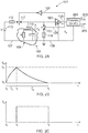
- Fig. 2B shows a plot of the voltage V in of the capacitor 111 during a charging and discharging cycle for the apparatus 101 shown in Fig. 2A .
- the first switch 117 is closed and the second switch 121 is opened. This enables charging of the capacitor 111 through the first circuit loop 107.
- the threshold voltage V 1 may be any predetermined voltage level between sero and the voltage level of the power source 113. In some examples the threshold voltage V 1 may be the fully charged voltage of the capacitor 111 or the voltage of the capacitor 111 when it is substantially fully charged. The fully charged maximum voltage level could be the voltage level of the power source 113.
- the time taken to reach the threshold voltage V 1 may be indicative of the time constant T 1 .
- the time constant T 1 is dependent upon the resistance of the first resistor 115 and the impedance of the subject 105.
- the control circuitry 123 provides a first control signal 127 to open the first switch 117 and a second control signal 129 to close the second switch 121. This breaks the first circuit loop 107 and completes the second circuit loop 109. This enables the capacitor 111 to be discharged through the second circuit loop 109. The capacitor 111 is discharged until a lower threshold voltage V 2 is reached. In the example of Fig. 2B the lower threshold voltage V 2 is zero, or substantially zero.
- the lower threshold voltage V 2 is reached.
- the time taken to reach the lower threshold voltage V 2 may be indicative of the time constant T 2 .
- the time constant T 2 is dependent upon the resistance of the second resistor 119 and the impedance of the subject 105.
- the first time constant T 1 and the second time constant T 2 also have different values.
- Fig. 2C shows a plot of the output signal 125 provided by the control circuitry 123 during the charging and discharging cycle.
- the voltage of the capacitor 111 is below the threshold voltage V 1 and so the voltage V s of the control circuitry 123 is zero, or substantially zero, during this time period.
- the threshold voltage V 1 is reached, at time t 1 then the voltage V s of the output signal 125 is increased to a non-zero value.
- the voltage of the capacitor 111 is above the lower threshold voltage V 2 and so the voltage V s of the output signal 125 remains at the non-zero value during this time period.
- the output of the control circuitry 123 remains at a constant value, or a substantially constant value, during this time period.
- the output signal 125 of the control circuit 123 is a series of pulses where the duration of the pulses is indicative of the time constants T 1 and T 2 .
- the values of the capacitance and the resistance of the subject 105 can be estimated from the duration of the pulses so as to provide the first output signal 203 and the second output signal 205.
- Fig. 3A shows another example apparatus 101 according to examples of the disclosure.
- the apparatus 101 comprises circuitry 103 comprising a first circuit loop 107, a second circuit loop 109 and processing circuitry 201.
- the first circuit loop 107, the second circuit loop 109 and the processing circuitry 201 may be as shown in 2A.
- Corresponding reference numerals are used for corresponding features.
- the circuitry 103 comprises a first electrode 307 and a second electrode 309.
- the first electrode 307 and the second electrode 309 provide an interface between the subject 105 and the circuitry 103.
- the first electrode 307 and the second electrode 309 may comprise any suitable means which may enable the direct current signal from the circuitry 103 to be provided to the subject 105.
- the circuitry 103 is configured so that when the circuitry 103 is in use the electrodes 307, 309 may be provided in direct contact to the skin of the subject 105.
- the electrodes 307, 309 could comprise adhesive electrodes which may be adhered to the skin of the subject 105. Other types of electrode 307, 309 could be used in other examples of the disclosure.
- the apparatus 101 also comprises compensation circuitry 301.
- the compensation circuitry 301 may comprise any means which may be configured to detect a change in impedance at an interface between the circuitry 103 and the subject 105 and, in response to the detected change, adjust the resistance of the first resistor 115 and/or the second resistor 119.
- the change in the impedance at the interface could be caused by movement of the electrodes 307, 309, by dirt or moisture accumulating around the electrode 307 or by any other suitable factor.
- the compensation circuitry 301 is coupled to the control circuitry 123 so that an output signal 125 of the control circuitry 123 is provided to the compensation circuitry 301. This enables the compensation circuitry 301 to use the output signal 125 to determine if there has been a change in the impedance at an interface between the circuitry 103 and the subject 105.
- the compensation circuitry 301 is coupled to the first resistor 115 so that a first compensation signal 303 is provided from the compensation circuitry 301 to the first resistor 115.
- the first resistor 115 comprises a variable resistor and the first compensation signal 303 causes the resistance of the variable resistor to be controlled.
- the first compensation signal 303 may cause the resistance of the variable resistor to be increased, decreased or stay the same as is determined by the compensation circuitry 301.
- the compensation circuitry 301 is also coupled to the second resistor 119 so that a second compensation signal 305 is provided from the compensation circuitry 301 to the second resistor 119.
- the second resistor 119 comprises a variable resistor and the second compensation signal 305 causes the resistance of the variable resistor to be controlled.
- the second compensation signal 305 may cause the resistance of the variable resistor to be increased, decreased or stay the same as is determined by the compensation circuitry 301.
- the compensation circuitry 301 is configured to compensate for a change of the impedance at the interface between the subject 105 and the circuitry 103.
- the compensation circuitry 301 may be configured to compensate for a change of the impedance which is above a threshold value.
- the changes in impedance at the interface between the subject 105 and the circuitry 103 may be significantly larger than changes in impedance caused by biometric parameters. This may enable small changes in impedance to be discounted by the compensation circuitry 301. In such examples it is not necessary for the absolute value of the impedance at the interface between the subject 105 and the circuitry 103 to be determined.
- Fig. 3B shows a plot of the voltage V in of the capacitor 111 during a charging and discharging cycle for the apparatus 101 shown in Fig. 3A
- Fig. 3C shows a plot of the voltage V s of the output signal 125 provided by the control circuitry 123 during the charging and discharging cycle. These plots are similar to those shown in Figs. 2A and 2B .
- Fig. 4 shows an example embodiment of an electronic device 401 which may comprise an apparatus 101 such as the apparatus 101 described above.
- the electronic device 401 comprises a wearable device.
- the electronic device 401 is provided on a chest strap 403 which enables the apparatus 101 to be positioned adjacent to the torso of the subject 105.
- the chest strap 403 may provide attachment means which enable the electronic device 401 to be attached to the subject 105.
- the apparatus 101 could be positioned adjacent to other parts of the subject 105 such as an arm or a leg or any other suitable part. In such examples other types of attachment means may be provided instead of a chest strap.
- the electronic device 401 may also comprise one or more transceivers 405.
- the one or more transceivers 405 could be configured to enable data to be transmitted between the electronic device 401 and another device.
- the another device could be a mobile phone, a communications device or any other suitable type of device.
- the another device could comprise processing circuitry 201 which may be configured to estimate the impedance of the subject 105 from the output signal 125 of the electronic device 401.
- the electronic device 401 may be configured to communicate data from the electronic device 401 with or without local storage of the data in a memory provided within the electronic device 401 and with or without local processing of the data by circuitry or processors within the electronic device 401.
- the data may, for example, be measurement data from the circuitry 103.
- the data could be the duration of the pulses within the output signal 125 of the control circuitry 123.
- the data could be estimates of the time constants T 1 and T 2 which may have been obtained by processing the output signal 125 of the control circuitry 123.
- the data may be stored in processed or unprocessed format remotely at one or more devices.
- the data may be stored in the Cloud.
- the data may be processed remotely at one or more devices.
- the data may be partially processed locally and partially processed remotely at one or more devices.
- the data may be communicated to the remote devices wirelessly via short range radio communications such as Wi-Fi or Bluetooth, for example, or over long range cellular radio links.
- the data may be communicated via a human body communication (HBC) system or other suitable system.
- the apparatus may comprise a communications interface such as, for example, a radio transceiver for communication of data.
- the electronic device 401 may be part of the Internet of Things forming part of a larger, distributed network.
- the processing of the data may be for the purpose of health monitoring, data aggregation, patient monitoring, vital signs monitoring or other purposes.
- the processing of the data may produce an output.
- the output may be communicated to the electronic device 401 where it may produce an output sensible to the subject 105 such as an audio output, visual output or haptic output.
- Fig. 5 shows an example embodiment of a method. The method may be implemented using apparatus 101 and/or electronic devices as described above.
- the method comprises, at block 501, configuring circuitry 103 to provide a direct current signal to a subject 105.
- the method comprises configuring the circuitry 103 to enable charging of a capacitor 111 through a first current loop 107.
- the charging of the capacitor 111 enables measurement of a first time constant T 1 to be obtained where the first time constant T 1 is indicative of a charging time of the capacitor 111.
- the method also comprises, at block 505, configuring the circuitry 103 to enable discharging of the capacitor 111 through a second current loop 109.
- the discharging of the capacitor 111 enables measurement of a second time constant T 2 to be obtained where the second time constant T 2 is indicative of a discharging time of the capacitor 111.
- the first time constant T 1 and the second time constant T 2 enable an impedance of the subject 105 to be estimated.
- the impedance of the subject 105 could be estimated by processing circuitry.
- the impedance of the subject 105 could be estimated by using lookup tables or any other suitable means.
- Examples of the disclosure provide for an apparatus 101, electronic device 401 and method which enable the impedance of the subject 105 to be determined using a direct current signal. This may reduce the power requirements of the apparatus 101 and may reduce the complexity of the circuitry 103 needed compared to an apparatus 101 using an alternating current signal.
- this may enable the apparatus 101 to be used for extended periods of time. This may enable the apparatus 101 to be used in a wearable electronic device 401. This may enable the apparatus 101 to be used to monitor the impedance of the subject 105 over extended periods of time.
- coupled means operationally coupled. Any number or combination of intervening elements can exist between coupled components including no intervening elements.
- the above described examples find application as enabling components of: automotive systems; telecommunication systems; electronic systems including consumer electronic products; distributed computing systems; media systems for generating or rendering media content including audio, visual and audio visual content and mixed, mediated, virtual and/or augmented reality; personal systems including personal health systems or personal fitness systems; navigation systems; user interfaces also known as human machine interfaces; networks including cellular, non-cellular, and optical networks; ad-hoc networks; the internet; the internet of things; virtualized networks; and related software and services.
Landscapes
- Health & Medical Sciences (AREA)
- Life Sciences & Earth Sciences (AREA)
- Physics & Mathematics (AREA)
- Biomedical Technology (AREA)
- Medical Informatics (AREA)
- Biophysics (AREA)
- Pathology (AREA)
- Engineering & Computer Science (AREA)
- Nuclear Medicine, Radiotherapy & Molecular Imaging (AREA)
- Heart & Thoracic Surgery (AREA)
- Radiology & Medical Imaging (AREA)
- Molecular Biology (AREA)
- Surgery (AREA)
- Animal Behavior & Ethology (AREA)
- General Health & Medical Sciences (AREA)
- Public Health (AREA)
- Veterinary Medicine (AREA)
- General Physics & Mathematics (AREA)
- Measurement And Recording Of Electrical Phenomena And Electrical Characteristics Of The Living Body (AREA)
Claims (15)
- Einrichtung (101), die Folgendes umfasst:eine Schaltung (103), die dazu ausgelegt ist, einem Patienten (105) ein Gleichstromsignal bereitzustellen;wobei die Schaltung einen Kondensator (111) umfasst und die Schaltung dazu ausgelegt ist, zwischen einer ersten Schaltungsschleife (107), die den Kondensator und einen ersten Widerstand (115) umfasst, und einer zweiten Schaltungsschleife (109), die den Kondensator und einen zweiten Widerstand (119) umfasst, umzuschalten, und die erste Schaltungsschleife dazu ausgelegt ist, ein Laden des Kondensators zu ermöglichen, um eine Messung einer ersten Zeitkonstante, die zu erhalten ist, zu ermöglichen, wo die erste Zeitkonstante eine Ladezeit des Kondensators angibt, und die zweite Schaltungsschleife dazu ausgelegt ist, ein Entladen des Kondensators zu ermöglichen, um eine Messung einer zweiten Zeitkonstante, die zu erhalten ist, zu ermöglichen, wo die zweite Zeitkonstante eine Entladezeit des Kondensators angibt; undwobei die erste Zeitkonstante und die zweite Zeitkonstante eine Schätzung einer Impedanz des Patienten ermöglichen.
- Vorrichtung nach Anspruch 1, wobei die Schaltung derart ausgelegt ist, dass der Kondensator, wenn die Einrichtung in Gebrauch ist, mit dem Patienten in Reihe ist.
- Einrichtung nach einem der vorhergehenden Ansprüche, wobei die erste Schaltungsschleife eine Stromquelle umfasst.
- Einrichtung nach einem der vorhergehenden Ansprüche, wobei die erste Schaltungsschleife den ersten Widerstand in Reihe mit dem Kondensator umfasst und die zweite Schaltungsschleife den zweiten Widerstand in Reihe mit dem Kondensator umfasst.
- Einrichtung nach Anspruch 4, wobei der erste Widerstand einen anderen Widerstand hat als der zweite Widerstand.
- Einrichtung nach einem der Ansprüche 4 bis 5, die eine Kompensationsschaltung umfasst, die dazu ausgelegt ist, an einer Schnittstelle zwischen der Schaltung und dem Patienten eine Änderung der Impedanz zu detektieren und in Reaktion auf die detektierte Änderung den Widerstand des ersten Widerstands und/oder des zweiten Widerstands anzupassen.
- Einrichtung nach einem der vorhergehenden Ansprüche, die einen oder mehrere Schalter umfasst, die dazu ausgelegt sind, für eine erste Zeitperiode die erste Schaltungsschleife zu schließen und die zweite Schaltungsschleife zu öffnen und für die zweite Zeitperiode die zweite Schaltungsschleife zu schließen und die erste Schaltungsschleife zu öffnen, wobei sich die erste Zeitperiode von der zweiten Zeitperiode unterscheidet.
- Einrichtung nach Anspruch 7, die eine Steuerschaltung umfasst, die dazu ausgelegt ist, in Reaktion darauf, dass ein Schwellwertspannungsniveau erreicht wird, zu bewirken, dass ein erster Schalter geöffnet wird und ein zweiter Schalter geschlossen wird.
- Einrichtung nach Anspruch 8, wobei die Steuerschaltung dazu ausgelegt ist, Ausgangsimpulse bereitzustellen, wobei die Dauer der Ausgangsimpulse eine Anzeige der ersten Zeitkonstante und/oder der zweiten Zeitkonstante bereitstellt.
- Einrichtung nach Anspruch 9, die eine Verarbeitungsschaltung umfasst, die dazu ausgelegt ist, anhand der Ausgangsimpulse der Steuerschaltung eine Impedanz des Patienten zu schätzen.
- Einrichtung nach einem der Ansprüche 8 bis 9, wobei die Steuerschaltung mindestens eines von einem Schmitt-Trigger, einem Fensterkomparator umfasst, der dazu ausgelegt ist, die Position der Schalter darauf basierend, dass eine Schwellwertspannung erreicht wird, zu steuern.
- Einrichtung nach Anspruch 11, wobei die Impedanz des Patienten unter Verwendung von Nachschlagetabellen geschätzt wird.
- Einrichtung nach einem der vorhergehenden Ansprüche, die mindestens eine erste Elektrode und mindestens eine zweite Elektrode umfasst, die dazu ausgelegt sind, eine Schnittstelle zwischen der Schaltung und dem Patienten bereitzustellen.
- Elektronische Vorrichtung, die eine Einrichtung nach einem der vorhergehenden Ansprüche umfasst.
- Verfahren, das Folgendes umfasst:Auslegen (501) einer Schaltung, die einen Kondensator umfasst, um einem Patienten ein Gleichstromsignal bereitzustellen;Auslegen (503) der Schaltung, um ein Laden des Kondensators über eine erste Stromschleife, die den Kondensator und einen ersten Widerstand umfasst, zu ermöglichen, um eine Messung einer ersten Zeitkonstante, die zu erhalten ist, zu ermöglichen, wo die erste Zeitkonstante eine Ladezeit des Kondensators anzeigt; undAuslegen (505) der Schaltung, um ein Entladen des Kondensators über eine zweite Stromschleife, die den Kondensator und einen zweiten Widerstand umfasst, zu ermöglichen, um eine Messung einer zweiten Zeitkonstante, die zu erhalten ist, zu ermöglichen, wo die zweite Zeitkonstante eine Entladezeit des Kondensators anzeigt;wobei die erste Zeitkonstante und die zweite Zeitkonstante eine Schätzung einer Impedanz des Patienten ermöglichen.
Priority Applications (3)
| Application Number | Priority Date | Filing Date | Title |
|---|---|---|---|
| EP18167365.8A EP3553538B1 (de) | 2018-04-13 | 2018-04-13 | Vorrichtung, elektronische vorrichtung und verfahren zur impedanzschätzung |
| US17/044,876 US12138031B2 (en) | 2018-04-13 | 2019-04-11 | Apparatus, electronic device and method for estimating impedance |
| PCT/EP2019/059209 WO2019197517A1 (en) | 2018-04-13 | 2019-04-11 | An apparatus, electronic device and method for estimating impedance |
Applications Claiming Priority (1)
| Application Number | Priority Date | Filing Date | Title |
|---|---|---|---|
| EP18167365.8A EP3553538B1 (de) | 2018-04-13 | 2018-04-13 | Vorrichtung, elektronische vorrichtung und verfahren zur impedanzschätzung |
Publications (2)
| Publication Number | Publication Date |
|---|---|
| EP3553538A1 EP3553538A1 (de) | 2019-10-16 |
| EP3553538B1 true EP3553538B1 (de) | 2021-03-10 |
Family
ID=62002032
Family Applications (1)
| Application Number | Title | Priority Date | Filing Date |
|---|---|---|---|
| EP18167365.8A Active EP3553538B1 (de) | 2018-04-13 | 2018-04-13 | Vorrichtung, elektronische vorrichtung und verfahren zur impedanzschätzung |
Country Status (3)
| Country | Link |
|---|---|
| US (1) | US12138031B2 (de) |
| EP (1) | EP3553538B1 (de) |
| WO (1) | WO2019197517A1 (de) |
Family Cites Families (19)
| Publication number | Priority date | Publication date | Assignee | Title |
|---|---|---|---|---|
| US5678547A (en) | 1988-12-22 | 1997-10-21 | Biofield Corp. | Method and apparatus for screening or sensing bodily conditions using DC biopotentials |
| DE4420998C2 (de) * | 1994-06-17 | 1999-03-25 | Diehl Stiftung & Co | Schaltungseinrichtung zum genauen Messen eines elektrischen Widerstandes |
| JP3621586B2 (ja) | 1998-06-02 | 2005-02-16 | グローリー工業株式会社 | 抵抗値測定回路及びその測定方法 |
| AU759937B2 (en) | 1998-07-06 | 2003-05-01 | Pastor, Aleksander | Apparatus for evaluation of skin impedance variations |
| JP3907353B2 (ja) | 1999-08-26 | 2007-04-18 | 株式会社タニタ | 生体インピーダンス測定装置 |
| FR2806311B1 (fr) | 2000-03-14 | 2002-10-18 | Ela Medical Sa | Dispositif medical implantable actif, notamment stimulateur cardiaque, defibrillateur et/ou cardioverteur et/ou dispositif multisite comportant des moyens de mesure de bioimpedance transseptale |
| DE10028671B4 (de) * | 2000-03-29 | 2006-02-02 | Datron-Electronic Gmbh | Werkzeugmaschine |
| US7006078B2 (en) | 2002-05-07 | 2006-02-28 | Mcquint, Inc. | Apparatus and method for sensing the degree and touch strength of a human body on a sensor |
| ATE313788T1 (de) * | 2002-10-18 | 2006-01-15 | Siemens Schweiz Ag | Feuchtigkeitsfühler mit kapazitivem feuchte- messelement und verfahren zur erfassung der luftfeuchtigkeit |
| CN2623167Y (zh) * | 2002-11-14 | 2004-07-07 | 精量电子(深圳)有限公司 | 带有透明电极之人体脂肪秤 |
| JP4024774B2 (ja) | 2004-04-05 | 2007-12-19 | 株式会社タニタ | 体脂肪測定装置 |
| JP4510526B2 (ja) * | 2004-06-07 | 2010-07-28 | 株式会社バイオエコーネット | 赤外線体温計 |
| US7173438B2 (en) * | 2005-05-18 | 2007-02-06 | Seagate Technology Llc | Measuring capacitance |
| DE102008042765A1 (de) * | 2008-10-13 | 2010-04-15 | Robert Bosch Gmbh | Vorrichtung und Verfahren zum Messen eines Widerstandswerts |
| WO2011074683A1 (ja) * | 2009-12-15 | 2011-06-23 | 株式会社ピューズ | 絶縁劣化検出装置 |
| DE102012204569B3 (de) * | 2012-03-22 | 2013-08-22 | Continental Automotive Gmbh | Vorrichtung und Verfahren zum Messen des Wertes eines Widerstands |
| US9482706B2 (en) * | 2012-12-11 | 2016-11-01 | Dust Company, Inc. | Methods and circuits for measuring a high impedance element based on time constant measurements |
| US9770185B2 (en) * | 2014-08-06 | 2017-09-26 | Verily Life Sciences Llc | Sharing a single electrode between skin resistance and capacitance measurements |
| US10092203B2 (en) * | 2015-08-21 | 2018-10-09 | Verily Life Sciences Llc | Using skin resistance measurements to determine timing of bio-telemetry measurements |
-
2018
- 2018-04-13 EP EP18167365.8A patent/EP3553538B1/de active Active
-
2019
- 2019-04-11 WO PCT/EP2019/059209 patent/WO2019197517A1/en not_active Ceased
- 2019-04-11 US US17/044,876 patent/US12138031B2/en active Active
Non-Patent Citations (1)
| Title |
|---|
| None * |
Also Published As
| Publication number | Publication date |
|---|---|
| EP3553538A1 (de) | 2019-10-16 |
| WO2019197517A1 (en) | 2019-10-17 |
| US12138031B2 (en) | 2024-11-12 |
| US20210100473A1 (en) | 2021-04-08 |
Similar Documents
| Publication | Publication Date | Title |
|---|---|---|
| US8606177B2 (en) | Apparatus and method for controlling human body contact of ground electrode, and human body communication system using the same | |
| CN107925488B (zh) | 用于传感器优化及配置的方法、装置和设备 | |
| US10485433B2 (en) | Reliable estimation of pulse transit time in motion for cuffless blood pressure estimation | |
| US11521753B2 (en) | Contextual annotation of medical data | |
| KR20150133460A (ko) | 전자 장치의 배터리 관리 방법 및 이를 수행하는 전자 장치 | |
| US10959641B2 (en) | Apparatus and method for measuring bioelectrical impedance and apparatus and method for measuring biometric information | |
| Jeon et al. | A 2.5-nW radio platform with an internal wake-up receiver for smart contact lens using a single loop antenna | |
| US10006950B2 (en) | Impedance measurement circuit | |
| KR20170025069A (ko) | 생체 신호 취득 방법 및 이를 지원하는 전자 장치 | |
| CN105940614B (zh) | 用于提供通信的设备和方法 | |
| CN109738004A (zh) | 接近传感器的校准方法与装置、电子设备及存储介质 | |
| Nishida et al. | Equivalent circuit model viewed from receiver side in human body communication | |
| Liu et al. | Non-contact, real-time eye blink detection with capacitive sensing | |
| US9671258B2 (en) | Wearable device with removal-detection function | |
| EP3767967B1 (de) | Fernmessung | |
| US9974452B2 (en) | Inductive non-contact resistance measurement | |
| EP3553538B1 (de) | Vorrichtung, elektronische vorrichtung und verfahren zur impedanzschätzung | |
| Shinagawa et al. | Noise analysis for intra-body communication based on parasitic capacitance measurement | |
| CN112022081B (zh) | 一种检测视力的方法、终端设备以及计算机可读存储介质 | |
| CN107005607B (zh) | 在通信装置中执行的方法、通信装置和计算机可读介质 | |
| CN107968889A (zh) | 闹铃提示方法、装置、移动终端及计算机存储介质 | |
| CN115005156A (zh) | 动物死亡的判别方法、装置、存储介质及电子设备 | |
| CN104887212A (zh) | 一种运动员健康监测系统 | |
| Dobrostomat et al. | Wearable health monitors with TransferJet data communications and inductive power transfer | |
| CN119496240A (zh) | 电源电路和相关装置 |
Legal Events
| Date | Code | Title | Description |
|---|---|---|---|
| PUAI | Public reference made under article 153(3) epc to a published international application that has entered the european phase |
Free format text: ORIGINAL CODE: 0009012 |
|
| STAA | Information on the status of an ep patent application or granted ep patent |
Free format text: STATUS: THE APPLICATION HAS BEEN PUBLISHED |
|
| AK | Designated contracting states |
Kind code of ref document: A1 Designated state(s): AL AT BE BG CH CY CZ DE DK EE ES FI FR GB GR HR HU IE IS IT LI LT LU LV MC MK MT NL NO PL PT RO RS SE SI SK SM TR |
|
| AX | Request for extension of the european patent |
Extension state: BA ME |
|
| STAA | Information on the status of an ep patent application or granted ep patent |
Free format text: STATUS: REQUEST FOR EXAMINATION WAS MADE |
|
| 17P | Request for examination filed |
Effective date: 20200416 |
|
| RBV | Designated contracting states (corrected) |
Designated state(s): AL AT BE BG CH CY CZ DE DK EE ES FI FR GB GR HR HU IE IS IT LI LT LU LV MC MK MT NL NO PL PT RO RS SE SI SK SM TR |
|
| GRAP | Despatch of communication of intention to grant a patent |
Free format text: ORIGINAL CODE: EPIDOSNIGR1 |
|
| STAA | Information on the status of an ep patent application or granted ep patent |
Free format text: STATUS: GRANT OF PATENT IS INTENDED |
|
| RIC1 | Information provided on ipc code assigned before grant |
Ipc: G01R 27/02 20060101AFI20200915BHEP Ipc: A61B 5/02 20060101ALI20200915BHEP Ipc: A61B 5/00 20060101ALI20200915BHEP Ipc: A61B 5/053 20060101ALI20200915BHEP |
|
| INTG | Intention to grant announced |
Effective date: 20200930 |
|
| GRAS | Grant fee paid |
Free format text: ORIGINAL CODE: EPIDOSNIGR3 |
|
| GRAA | (expected) grant |
Free format text: ORIGINAL CODE: 0009210 |
|
| STAA | Information on the status of an ep patent application or granted ep patent |
Free format text: STATUS: THE PATENT HAS BEEN GRANTED |
|
| AK | Designated contracting states |
Kind code of ref document: B1 Designated state(s): AL AT BE BG CH CY CZ DE DK EE ES FI FR GB GR HR HU IE IS IT LI LT LU LV MC MK MT NL NO PL PT RO RS SE SI SK SM TR |
|
| REG | Reference to a national code |
Ref country code: GB Ref legal event code: FG4D |
|
| REG | Reference to a national code |
Ref country code: CH Ref legal event code: EP Ref country code: AT Ref legal event code: REF Ref document number: 1370414 Country of ref document: AT Kind code of ref document: T Effective date: 20210315 |
|
| REG | Reference to a national code |
Ref country code: IE Ref legal event code: FG4D |
|
| REG | Reference to a national code |
Ref country code: DE Ref legal event code: R096 Ref document number: 602018013577 Country of ref document: DE |
|
| REG | Reference to a national code |
Ref country code: NL Ref legal event code: FP |
|
| REG | Reference to a national code |
Ref country code: LT Ref legal event code: MG9D |
|
| PG25 | Lapsed in a contracting state [announced via postgrant information from national office to epo] |
Ref country code: GR Free format text: LAPSE BECAUSE OF FAILURE TO SUBMIT A TRANSLATION OF THE DESCRIPTION OR TO PAY THE FEE WITHIN THE PRESCRIBED TIME-LIMIT Effective date: 20210611 Ref country code: HR Free format text: LAPSE BECAUSE OF FAILURE TO SUBMIT A TRANSLATION OF THE DESCRIPTION OR TO PAY THE FEE WITHIN THE PRESCRIBED TIME-LIMIT Effective date: 20210310 Ref country code: FI Free format text: LAPSE BECAUSE OF FAILURE TO SUBMIT A TRANSLATION OF THE DESCRIPTION OR TO PAY THE FEE WITHIN THE PRESCRIBED TIME-LIMIT Effective date: 20210310 Ref country code: BG Free format text: LAPSE BECAUSE OF FAILURE TO SUBMIT A TRANSLATION OF THE DESCRIPTION OR TO PAY THE FEE WITHIN THE PRESCRIBED TIME-LIMIT Effective date: 20210610 Ref country code: NO Free format text: LAPSE BECAUSE OF FAILURE TO SUBMIT A TRANSLATION OF THE DESCRIPTION OR TO PAY THE FEE WITHIN THE PRESCRIBED TIME-LIMIT Effective date: 20210610 Ref country code: LT Free format text: LAPSE BECAUSE OF FAILURE TO SUBMIT A TRANSLATION OF THE DESCRIPTION OR TO PAY THE FEE WITHIN THE PRESCRIBED TIME-LIMIT Effective date: 20210310 |
|
| REG | Reference to a national code |
Ref country code: AT Ref legal event code: MK05 Ref document number: 1370414 Country of ref document: AT Kind code of ref document: T Effective date: 20210310 |
|
| PG25 | Lapsed in a contracting state [announced via postgrant information from national office to epo] |
Ref country code: SE Free format text: LAPSE BECAUSE OF FAILURE TO SUBMIT A TRANSLATION OF THE DESCRIPTION OR TO PAY THE FEE WITHIN THE PRESCRIBED TIME-LIMIT Effective date: 20210310 Ref country code: LV Free format text: LAPSE BECAUSE OF FAILURE TO SUBMIT A TRANSLATION OF THE DESCRIPTION OR TO PAY THE FEE WITHIN THE PRESCRIBED TIME-LIMIT Effective date: 20210310 Ref country code: RS Free format text: LAPSE BECAUSE OF FAILURE TO SUBMIT A TRANSLATION OF THE DESCRIPTION OR TO PAY THE FEE WITHIN THE PRESCRIBED TIME-LIMIT Effective date: 20210310 |
|
| PG25 | Lapsed in a contracting state [announced via postgrant information from national office to epo] |
Ref country code: EE Free format text: LAPSE BECAUSE OF FAILURE TO SUBMIT A TRANSLATION OF THE DESCRIPTION OR TO PAY THE FEE WITHIN THE PRESCRIBED TIME-LIMIT Effective date: 20210310 Ref country code: CZ Free format text: LAPSE BECAUSE OF FAILURE TO SUBMIT A TRANSLATION OF THE DESCRIPTION OR TO PAY THE FEE WITHIN THE PRESCRIBED TIME-LIMIT Effective date: 20210310 Ref country code: AT Free format text: LAPSE BECAUSE OF FAILURE TO SUBMIT A TRANSLATION OF THE DESCRIPTION OR TO PAY THE FEE WITHIN THE PRESCRIBED TIME-LIMIT Effective date: 20210310 Ref country code: SM Free format text: LAPSE BECAUSE OF FAILURE TO SUBMIT A TRANSLATION OF THE DESCRIPTION OR TO PAY THE FEE WITHIN THE PRESCRIBED TIME-LIMIT Effective date: 20210310 |
|
| PG25 | Lapsed in a contracting state [announced via postgrant information from national office to epo] |
Ref country code: IS Free format text: LAPSE BECAUSE OF FAILURE TO SUBMIT A TRANSLATION OF THE DESCRIPTION OR TO PAY THE FEE WITHIN THE PRESCRIBED TIME-LIMIT Effective date: 20210710 Ref country code: RO Free format text: LAPSE BECAUSE OF FAILURE TO SUBMIT A TRANSLATION OF THE DESCRIPTION OR TO PAY THE FEE WITHIN THE PRESCRIBED TIME-LIMIT Effective date: 20210310 Ref country code: SK Free format text: LAPSE BECAUSE OF FAILURE TO SUBMIT A TRANSLATION OF THE DESCRIPTION OR TO PAY THE FEE WITHIN THE PRESCRIBED TIME-LIMIT Effective date: 20210310 Ref country code: PT Free format text: LAPSE BECAUSE OF FAILURE TO SUBMIT A TRANSLATION OF THE DESCRIPTION OR TO PAY THE FEE WITHIN THE PRESCRIBED TIME-LIMIT Effective date: 20210712 Ref country code: PL Free format text: LAPSE BECAUSE OF FAILURE TO SUBMIT A TRANSLATION OF THE DESCRIPTION OR TO PAY THE FEE WITHIN THE PRESCRIBED TIME-LIMIT Effective date: 20210310 |
|
| REG | Reference to a national code |
Ref country code: DE Ref legal event code: R097 Ref document number: 602018013577 Country of ref document: DE |
|
| PG25 | Lapsed in a contracting state [announced via postgrant information from national office to epo] |
Ref country code: LU Free format text: LAPSE BECAUSE OF NON-PAYMENT OF DUE FEES Effective date: 20210413 |
|
| PLBE | No opposition filed within time limit |
Free format text: ORIGINAL CODE: 0009261 |
|
| STAA | Information on the status of an ep patent application or granted ep patent |
Free format text: STATUS: NO OPPOSITION FILED WITHIN TIME LIMIT |
|
| REG | Reference to a national code |
Ref country code: BE Ref legal event code: MM Effective date: 20210430 |
|
| PG25 | Lapsed in a contracting state [announced via postgrant information from national office to epo] |
Ref country code: MC Free format text: LAPSE BECAUSE OF FAILURE TO SUBMIT A TRANSLATION OF THE DESCRIPTION OR TO PAY THE FEE WITHIN THE PRESCRIBED TIME-LIMIT Effective date: 20210310 Ref country code: LI Free format text: LAPSE BECAUSE OF NON-PAYMENT OF DUE FEES Effective date: 20210430 Ref country code: CH Free format text: LAPSE BECAUSE OF NON-PAYMENT OF DUE FEES Effective date: 20210430 Ref country code: DK Free format text: LAPSE BECAUSE OF FAILURE TO SUBMIT A TRANSLATION OF THE DESCRIPTION OR TO PAY THE FEE WITHIN THE PRESCRIBED TIME-LIMIT Effective date: 20210310 Ref country code: AL Free format text: LAPSE BECAUSE OF FAILURE TO SUBMIT A TRANSLATION OF THE DESCRIPTION OR TO PAY THE FEE WITHIN THE PRESCRIBED TIME-LIMIT Effective date: 20210310 Ref country code: ES Free format text: LAPSE BECAUSE OF FAILURE TO SUBMIT A TRANSLATION OF THE DESCRIPTION OR TO PAY THE FEE WITHIN THE PRESCRIBED TIME-LIMIT Effective date: 20210310 |
|
| 26N | No opposition filed |
Effective date: 20211213 |
|
| PG25 | Lapsed in a contracting state [announced via postgrant information from national office to epo] |
Ref country code: SI Free format text: LAPSE BECAUSE OF FAILURE TO SUBMIT A TRANSLATION OF THE DESCRIPTION OR TO PAY THE FEE WITHIN THE PRESCRIBED TIME-LIMIT Effective date: 20210310 |
|
| PG25 | Lapsed in a contracting state [announced via postgrant information from national office to epo] |
Ref country code: IT Free format text: LAPSE BECAUSE OF FAILURE TO SUBMIT A TRANSLATION OF THE DESCRIPTION OR TO PAY THE FEE WITHIN THE PRESCRIBED TIME-LIMIT Effective date: 20210310 Ref country code: IE Free format text: LAPSE BECAUSE OF NON-PAYMENT OF DUE FEES Effective date: 20210413 |
|
| PG25 | Lapsed in a contracting state [announced via postgrant information from national office to epo] |
Ref country code: IS Free format text: LAPSE BECAUSE OF FAILURE TO SUBMIT A TRANSLATION OF THE DESCRIPTION OR TO PAY THE FEE WITHIN THE PRESCRIBED TIME-LIMIT Effective date: 20210710 Ref country code: FR Free format text: LAPSE BECAUSE OF NON-PAYMENT OF DUE FEES Effective date: 20210510 |
|
| PG25 | Lapsed in a contracting state [announced via postgrant information from national office to epo] |
Ref country code: BE Free format text: LAPSE BECAUSE OF NON-PAYMENT OF DUE FEES Effective date: 20210430 |
|
| GBPC | Gb: european patent ceased through non-payment of renewal fee |
Effective date: 20220413 |
|
| PG25 | Lapsed in a contracting state [announced via postgrant information from national office to epo] |
Ref country code: GB Free format text: LAPSE BECAUSE OF NON-PAYMENT OF DUE FEES Effective date: 20220413 |
|
| PG25 | Lapsed in a contracting state [announced via postgrant information from national office to epo] |
Ref country code: CY Free format text: LAPSE BECAUSE OF FAILURE TO SUBMIT A TRANSLATION OF THE DESCRIPTION OR TO PAY THE FEE WITHIN THE PRESCRIBED TIME-LIMIT Effective date: 20210310 |
|
| P01 | Opt-out of the competence of the unified patent court (upc) registered |
Effective date: 20230527 |
|
| PG25 | Lapsed in a contracting state [announced via postgrant information from national office to epo] |
Ref country code: HU Free format text: LAPSE BECAUSE OF FAILURE TO SUBMIT A TRANSLATION OF THE DESCRIPTION OR TO PAY THE FEE WITHIN THE PRESCRIBED TIME-LIMIT; INVALID AB INITIO Effective date: 20180413 |
|
| PG25 | Lapsed in a contracting state [announced via postgrant information from national office to epo] |
Ref country code: MK Free format text: LAPSE BECAUSE OF FAILURE TO SUBMIT A TRANSLATION OF THE DESCRIPTION OR TO PAY THE FEE WITHIN THE PRESCRIBED TIME-LIMIT Effective date: 20210310 |
|
| PG25 | Lapsed in a contracting state [announced via postgrant information from national office to epo] |
Ref country code: MT Free format text: LAPSE BECAUSE OF FAILURE TO SUBMIT A TRANSLATION OF THE DESCRIPTION OR TO PAY THE FEE WITHIN THE PRESCRIBED TIME-LIMIT Effective date: 20210310 |
|
| PGFP | Annual fee paid to national office [announced via postgrant information from national office to epo] |
Ref country code: NL Payment date: 20250317 Year of fee payment: 8 |
|
| PGFP | Annual fee paid to national office [announced via postgrant information from national office to epo] |
Ref country code: DE Payment date: 20250305 Year of fee payment: 8 |
|
| PG25 | Lapsed in a contracting state [announced via postgrant information from national office to epo] |
Ref country code: TR Free format text: LAPSE BECAUSE OF FAILURE TO SUBMIT A TRANSLATION OF THE DESCRIPTION OR TO PAY THE FEE WITHIN THE PRESCRIBED TIME-LIMIT Effective date: 20210310 |