US10959641B2 - Apparatus and method for measuring bioelectrical impedance and apparatus and method for measuring biometric information - Google Patents
Apparatus and method for measuring bioelectrical impedance and apparatus and method for measuring biometric information Download PDFInfo
- Publication number
- US10959641B2 US10959641B2 US15/878,881 US201815878881A US10959641B2 US 10959641 B2 US10959641 B2 US 10959641B2 US 201815878881 A US201815878881 A US 201815878881A US 10959641 B2 US10959641 B2 US 10959641B2
- Authority
- US
- United States
- Prior art keywords
- measurement mode
- impedance
- electrode
- switch
- measurement
- Prior art date
- Legal status (The legal status is an assumption and is not a legal conclusion. Google has not performed a legal analysis and makes no representation as to the accuracy of the status listed.)
- Active, expires
Links
Images


Classifications
-
- A—HUMAN NECESSITIES
- A61—MEDICAL OR VETERINARY SCIENCE; HYGIENE
- A61B—DIAGNOSIS; SURGERY; IDENTIFICATION
- A61B5/00—Measuring for diagnostic purposes; Identification of persons
- A61B5/05—Detecting, measuring or recording for diagnosis by means of electric currents or magnetic fields; Measuring using microwaves or radio waves
- A61B5/053—Measuring electrical impedance or conductance of a portion of the body
- A61B5/0537—Measuring body composition by impedance, e.g. tissue hydration or fat content
-
- A—HUMAN NECESSITIES
- A61—MEDICAL OR VETERINARY SCIENCE; HYGIENE
- A61B—DIAGNOSIS; SURGERY; IDENTIFICATION
- A61B5/00—Measuring for diagnostic purposes; Identification of persons
- A61B5/05—Detecting, measuring or recording for diagnosis by means of electric currents or magnetic fields; Measuring using microwaves or radio waves
- A61B5/053—Measuring electrical impedance or conductance of a portion of the body
-
- A—HUMAN NECESSITIES
- A61—MEDICAL OR VETERINARY SCIENCE; HYGIENE
- A61B—DIAGNOSIS; SURGERY; IDENTIFICATION
- A61B5/00—Measuring for diagnostic purposes; Identification of persons
- A61B5/48—Other medical applications
- A61B5/4869—Determining body composition
-
- A—HUMAN NECESSITIES
- A61—MEDICAL OR VETERINARY SCIENCE; HYGIENE
- A61B—DIAGNOSIS; SURGERY; IDENTIFICATION
- A61B5/00—Measuring for diagnostic purposes; Identification of persons
- A61B5/48—Other medical applications
- A61B5/4869—Determining body composition
- A61B5/4872—Body fat
-
- A—HUMAN NECESSITIES
- A61—MEDICAL OR VETERINARY SCIENCE; HYGIENE
- A61B—DIAGNOSIS; SURGERY; IDENTIFICATION
- A61B5/00—Measuring for diagnostic purposes; Identification of persons
- A61B5/48—Other medical applications
- A61B5/4869—Determining body composition
- A61B5/4875—Hydration status, fluid retention of the body
-
- A—HUMAN NECESSITIES
- A61—MEDICAL OR VETERINARY SCIENCE; HYGIENE
- A61B—DIAGNOSIS; SURGERY; IDENTIFICATION
- A61B5/00—Measuring for diagnostic purposes; Identification of persons
- A61B5/72—Signal processing specially adapted for physiological signals or for diagnostic purposes
- A61B5/7271—Specific aspects of physiological measurement analysis
- A61B5/7278—Artificial waveform generation or derivation, e.g. synthesising signals from measured signals
Definitions
- Apparatuses and methods consistent with exemplary embodiments relate to apparatuses and methods for measuring bioelectrical impedance and apparatuses and methods for measuring biometric information.
- bioelectrical impedance may be used to monitor the health or emotional state of a living body.
- various studies have been conducted to miniaturize devices for measuring the bioelectrical impedance and measure the bioelectrical impedance more quickly and accurately.
- One or more exemplary embodiments provide an apparatus and a method for measuring bioelectrical impedance more quickly and accurately.
- One or more exemplary embodiments also provide an apparatus and a method for measuring bioelectrical information more quickly and accurately.
- an apparatus for measuring bioelectrical impedance including: a first electrode; a second electrode; a third electrode; a fourth electrode; a current source configured to apply a constant current to an object through a first electrode and a second electrode; a measurement mode switcher configured to switch a measurement mode from a first measurement mode to a second measurement mode in response to a measurement mode switch signal; a voltmeter configured to obtain a voltage applied to a third electrode and a fourth electrode due to the constant current applied to the object through the first electrode and the second electrode, in the first measurement mode and the second measurement mode, respectively; and a processor configured to obtain first impedance based on a first voltage obtained by the voltmeter immediately before start of a measurement mode switch from the first measurement mode to the second measurement mode, obtain second impedance based on a second voltage obtained by the voltmeter immediately after completion of the measurement mode switch from the first measurement mode to the second measurement mode, and obtain bioelectrical impedance of the object based on the
- a four-point impedance measurement method may be used in the first measurement mode, and a two-point impedance measurement method may be used in the second measurement mode.
- the measurement mode switcher may switch the measurement mode from the first measurement mode to the second measurement mode by short-circuiting the first electrode and the third electrode to each other and short-circuiting the second electrode and the fourth electrode to each other.
- the processor may generate the measurement mode switch signal in response to determining that a predetermined period of time elapses in the first measurement mode.
- the processor may generate the measurement mode switch signal in response to determining that the first impedance of the first measurement mode exceeds a predetermined first threshold.
- the processor may determine a time point of the completion of the measurement mode switch from the first measurement mode to the second measurement mode.
- the processor may determine the time point of the completion of the measurement mode switch from the first measurement mode to the second measurement mode by monitoring measurement impedance based on the voltage obtained by the voltmeter after the start of the measurement mode switch from the first measurement mode to the second measurement mode.
- the processor may determine a time point at which a change of the measurement impedance turns from positive (+) to negative ( ⁇ ) as the time point of the completion of the measurement mode switch from the first measurement mode to the second measurement mode.
- the apparatus may further include a controller configured to control the voltmeter, the measurement mode switcher, and the processor to repeat operations of obtaining the voltage, switching the measurement mode, and obtaining the first impedance, the second impedance, and the bioelectrical impedance until a difference between currently obtained bioelectrical impedance and bioelectrical impedance obtained immediately before the currently obtained bioelectrical impedance becomes equal to or less than a predetermined threshold.
- a controller configured to control the voltmeter, the measurement mode switcher, and the processor to repeat operations of obtaining the voltage, switching the measurement mode, and obtaining the first impedance, the second impedance, and the bioelectrical impedance until a difference between currently obtained bioelectrical impedance and bioelectrical impedance obtained immediately before the currently obtained bioelectrical impedance becomes equal to or less than a predetermined threshold.
- the controller may determine the obtained bioelectrical impedance as the bioelectrical impedance of the object in response to determining that the difference between the currently obtained bioelectrical impedance and the bioelectrical impedance obtained immediately before the currently obtained bioelectrical impedance is equal to or less than the predetermined threshold.
- an apparatus for measuring bioelectrical impedance including: a first electrode; a second electrode; a third electrode; a fourth electrode; a current source configured to apply a constant current to an object through a first electrode and a second electrode; a measurement mode switcher configured to switch a measurement mode from a second measurement mode to a first measurement mode in response to a measurement mode switch signal; a voltmeter configured to obtain a voltage applied to a third electrode and a fourth electrode due to the constant current applied to the object through the first electrode and the second electrode, in the first measurement mode and the second measurement mode, respectively; and a processor configured to obtain second impedance based on a second voltage obtained by the voltmeter immediately before start of a measurement mode switch from the second measurement mode to the first measurement mode, obtain first impedance based on a first voltage obtained by the voltmeter immediately after completion of the measurement mode switch from the second measurement mode to the first measurement mode, and obtain bioelectrical impedance of the object based on the
- a four-point impedance measurement method may be used in the first measurement mode, and a two-point impedance measurement method may be used in the second measurement mode.
- the measurement mode switcher may switch the measurement mode from the second measurement mode to the first measurement mode by opening the first electrode and the third electrode, which are short-circuited to each other in the second measurement mode, and opening the second electrode and the fourth electrode, which are short-circuited to each other in the second measurement mode.
- the processor may generate the measurement mode switch signal in response to determining that the second impedance of the second measurement mode is less than a predetermined second threshold.
- the predetermined second threshold may be set in consideration of a dynamic range of the apparatus for measuring the bioelectrical impedance.
- the processor may determine a time point of the completion of the measurement mode switch from the second measurement mode to the first measurement mode by monitoring measurement impedance based on the voltage obtained by the voltmeter after the start of the measurement mode switch from the second measurement mode to the first measurement mode.
- the processor may determine a time point at which a change of the measurement impedance turns from negative ( ⁇ ) to positive (+) as the time point of the completion of the measurement mode switch from the second measurement mode to the first measurement mode.
- a method of measuring bioelectrical impedance including: obtaining first impedance based on a first voltage of an object obtained immediately before start of a measurement mode switch from a first measurement mode to a second measurement mode; switching a measurement mode from the first measurement mode to the second measurement mode; obtaining second impedance based on a second voltage of the object obtained immediately after completion of the measurement mode switch from the first measurement mode to the second measurement mode; and obtaining bioelectrical impedance of the object based on the first impedance and the second impedance.
- a four-point impedance measurement method based on a first electrode, a second electrode, a third electrode, and a fourth electrode may be used in the first measurement mode, and a two-point impedance measurement method based on the third electrode and the fourth electrode may be used in the second measurement mode.
- the switching may include switching the measurement mode from the first measurement mode to the second measurement mode by short-circuiting the first electrode and the third electrode to each other and short-circuiting the second electrode and the fourth electrode to each other.
- the switching may include switching the measurement mode from the first measurement mode to the second measurement mode in response to determining that a predetermined period of time elapses in the first measurement mode and/or that the first impedance of the first measurement mode exceeds a predetermined first threshold.
- the obtaining the second impedance may include determining a time point of the completion the measurement mode switch from the first measurement mode to the second measurement mode by monitoring measurement impedance based on a voltage obtained after the start of the measurement mode switch from the first measurement mode to the second measurement mode.
- the determining the time point of the completion of the measurement mode switch may include determining a time point at which a change of the measurement impedance turns from positive (+) to negative ( ⁇ ) as the time point of the completion of the measurement mode switch from the first measurement mode to the second measurement mode.
- the method may further include repeatedly performing operations of obtaining the first impedance, switching from the first measurement mode to the second measurement mode, obtaining the second impedance, and obtaining the bioelectrical impedance until a difference between currently obtained bioelectrical impedance and bioelectrical impedance obtained immediately before the currently obtained bioelectrical impedance becomes equal to or less than a predetermined threshold.
- an apparatus for measuring biometric information including: a first electrode; a second electrode; a third electrode; a fourth electrode; a bioelectrical impedance measurer configured to obtain bioelectrical impedance of an object; and a biometric information estimator configured to estimate biometric information of the object based on the obtained bioelectrical impedance of the object, wherein the bioelectrical impedance measurer includes: a current source configured to apply a constant current to the object through a first electrode and a second electrode; a measurement mode switcher configured to switch a measurement mode from a first measurement mode to a second measurement mode in response to a measurement mode switch signal; a voltmeter configured to obtain a voltage applied to a third electrode and a fourth electrode due to the constant current applied to the object through the first electrode and the second electrode, in the first measurement mode and the second measurement mode, respectively; and a processor configured to obtain first impedance based on a first voltage obtained by the voltmeter immediately before start of a
- the biometric information may include at least one of a body fat percentage, a body fat mass, a muscle mass, a skeletal muscle mass, a basal metabolic rate, an intracellular water content, an extracellular water content, a body water content, an inorganic mass, and a visceral fat content.
- the biometric information estimator may estimate the biometric information by using a formula which defines a relationship between the bioelectrical impedance of the object and the biometric information of the object.
- FIG. 1 is a block diagram illustrating an apparatus for measuring bioelectrical impedance according to an exemplary embodiment
- FIG. 2 is a circuit diagram for describing an apparatus for measuring bioelectrical impedance according to an exemplary embodiment
- FIG. 3 is a graph for describing a relationship between contact impedance and first impedance of a first measurement mode and a relationship between the contact impedance and second impedance of a second measurement mode;
- FIG. 4 is a graph for describing a bioelectrical impedance measurement method according to an exemplary embodiment
- FIG. 5 is a graph for describing a bioelectrical impedance measurement method according to another exemplary embodiment
- FIG. 6 is a block diagram illustrating an apparatus for measuring bioelectrical impedance according to another exemplary embodiment
- FIG. 7 is a graph for describing a bioelectrical impedance measurement method according to another exemplary embodiment
- FIG. 8 is a flowchart illustrating a method of measuring bioelectrical impedance according to an exemplary embodiment
- FIG. 9 is a flowchart illustrating a method of measuring bioelectrical impedance according to another exemplary embodiment
- FIG. 10 is a flowchart illustrating a method of measuring bioelectrical impedance according to an exemplary embodiment
- FIG. 11 is a block diagram illustrating an apparatus for measuring biometric information according to an exemplary embodiment
- FIG. 12 is a flowchart illustrating a method of measuring biometric information according to an exemplary embodiment
- FIG. 13A is a schematic view illustrating a comparison between measurement time in a related art bioelectric impedance measurement method and measurement time in a bioelectric impedance measurement method according to an exemplary embodiment
- FIG. 13B shows comparative data between measurement accuracy in a related art bioelectric impedance measurement method and a measurement accuracy in a bioelectric impedance measurement method according to an exemplary embodiment.
- the expression, “at least one of a, b, and c,” should be understood as including only a, only b, only c, both a and b, both a and c, both b and c, or all of a, b, and c.
- FIG. 1 is a block diagram illustrating an exemplary embodiment of an apparatus for measuring bioelectrical impedance.
- An apparatus 100 for measuring bioelectrical impedance may be mounted in an electronic device.
- the electronic device may include, for example but not limited to, a mobile phone, a smartphone, a tablet computer, a notebook computer, a personal digital assistant (PDA), a portable multimedia player (PMP), a navigation system, an MP3 player, a digital camera, and a wearable device.
- the wearable device may include various types, such as a wristwatch type, a wrist band type, a ring type, a belt type, a necklace type, an ankle band type, a thigh band type, a forearm band type, and the like.
- the electronic device and the wearable device are not limited to the aforementioned examples.
- the apparatus 100 for measuring bioelectrical impedance is an apparatus capable of measuring bioelectrical impedance of an object using bioelectrical impedance analysis (BIA) and supports a first measurement mode and a second measurement mode.
- a four-point measurement method is used, which measures impedance using four electrodes
- a two-point measurement method is used, which measures impedance using two electrodes.
- the apparatus 100 may obtain bioelectrical impedance based on impedances measured in the first measurement mode and the second measurement mode.
- the apparatus 100 includes four electrodes 101 , 102 , 103 , and 104 , a current source 110 , a voltmeter 120 , a measurement mode switcher 130 , and a processor 140 .
- a first electrode 101 and a second electrode 102 are current-application electrodes used for applying a current to an object and a third electrode 103 and a fourth electrode 104 are voltage-measurement electrodes used for measuring a voltage applied to the object, due to a current applied through the first electrode 101 and the second electrode 102 .
- the current source 110 applies a current to the object through the first and second electrodes 101 and 102 .
- the current source 110 may apply a constant current of the same magnitude to the object through the first and second electrodes 101 and 102 .
- the voltmeter 120 measures a voltage of the object which is applied to both ends of the third electrode 103 and the fourth electrode 104 due to a current applied to the object through the first and second electrodes 101 and 102 .
- the measurement mode switcher 130 switches a measurement mode between the first measurement mode and the second measurement mode in response to a measurement mode switch signal of the processor 140 .
- the processor 1140 may, for example, a central processor unit (CPU).
- the measurement mode switcher 130 when the measurement mode switcher 130 receives a signal for switching from the first measurement mode to the second measurement mode (hereinafter, will be referred to as a “first measurement mode switch signal”) from the processor 140 , the measurement mode switcher 130 may switch from the first measurement mode to the second measurement mode by short-circuiting the first electrode 101 and the third electrode 103 which are open and short-circuiting the second electrode 102 and the fourth electrode 104 which are open.
- the measurement mode switcher 130 when the measurement mode switcher 130 receives a signal for switching from the second measurement mode to the first measurement mode (hereinafter, will be referred to as a “second measurement mode switch signal”) from the processor 140 , the measurement mode switcher 130 switches the measurement mode from the second measurement mode to the first measurement mode by opening the short-circuited first and third electrodes 101 and 103 and the short-circuited second and fourth electrodes 102 and 104 .
- the measurement mode switcher 130 may change the first measurement mode that uses four electrical electrodes into the second measurement mode that uses two electrical electrodes by short-circuiting the opened first and third electrodes 101 and 103 to each other and short-circuiting the opened second and fourth electrodes 102 and 104 to each other.
- the measurement mode switcher 130 may change the second measurement mode that uses two electrical electrodes into the first measurement mode that uses four electrical electrodes by opening the short-circuited first and third electrodes 101 and 103 and the short-circuited second and fourth electrodes 102 and 104 .
- the measurement mode switcher 130 may include two switches (refer to FIG. 2 ).
- the voltmeter 120 measures a voltage applied to the third electrode and the fourth electrode due to the constant current applied to the object in the first measurement mode, and measures a second voltage applied to the first electrode and the second electrode due to the constant current applied to the object in the second measurement mode.
- the processor 140 generates a measurement mode switch signal (e.g., the first measurement mode switch signal and the second measurement mode switch signal).
- a measurement mode switch signal e.g., the first measurement mode switch signal and the second measurement mode switch signal.
- the processor 140 may generate the first measurement mode switch signal when a predetermined period of time elapses in the first measurement mode (e.g., a predetermined period of time elapses after entering the first measurement mode), and may generate the second measurement mode switch signal when a predetermined period of time elapses in the second measurement mode (e.g., a predetermined period of time elapses after entering the second measurement mode).
- the predetermined period of time may be set by default or according to a user's input.
- the predetermined period of time that is set by default may be appropriately determined based on a time to obtain sufficient measurement data in each measurement mode.
- first impedance when impedance of the first measurement mode (hereinafter, will be referred to as “first impedance”) which is obtained based on a voltage of the object measured in the first measurement mode (hereinafter, will be referred to as a “first voltage”) is greater than a first threshold value, the processor 140 may generate the first measurement mode switch signal.
- second impedance when impedance of the second measurement mode (hereinafter, will be referred to as “second impedance”) which is obtained based on a voltage of the object measured in the second measurement mode (hereinafter, will be referred to a “second voltage”) is less than a second threshold value, the processor 140 may generate the second measurement mode switch signal.
- the first threshold value and the second threshold value may be set in consideration of a dynamic range of the apparatus 100 .
- the processor 140 may determine the completion time point of the measurement mode switch (e.g., the completion time point of measurement mode switch from the first measurement mode to the second measurement mode and/or the completion time point of measurement mode switch from the second measurement mode to the first measurement mode).
- the completion time point of the measurement mode switch refers to the time point when the measurement mode switch is completed in a circuit.
- the processor 140 may determine the completion time point of the measurement mode switch by monitoring the change in the measurement impedance obtained based on a voltage measured after the measurement mode switch starts.
- the processor 140 may monitor the measurement impedance after the measurement mode switch starts, and determine a turning point of the sign of a differential value of the measurement impedance (e.g., in the case of the switch from the first measurement mode to the second measurement mode, the time point at which the change of the measurement impedance is turned from positive (+) to negative ( ⁇ ), and in the case of switch from the second measurement mode to the first measurement mode, the time point at which the change of the measurement impedance is turned from negative ( ⁇ ) to positive (+)) as the completion time point of the measurement mode switch.
- a turning point of the sign of a differential value of the measurement impedance e.g., in the case of the switch from the first measurement mode to the second measurement mode, the time point at which the change of the measurement impedance is turned from positive (+) to negative ( ⁇ ), and in the case of switch from the second measurement mode to the first measurement mode, the time point at which the change of the measurement impedance is turned from negative ( ⁇ ) to positive (+)
- the processor 140 obtains the first impedance immediately before the start of measurement mode switch based on the first voltage measured immediately before the start of measurement mode switch from the first measurement mode to the second measurement mode, and obtains the second impedance immediately after the completion of the measurement mode switch based on the second voltage measured immediately after the completion of measurement mode switch from the first measurement mode to the second measurement mode.
- the processor 140 obtains the second impedance immediately before the start of measurement mode switch based on the second voltage measured immediate before the start of measurement mode switch from the second measurement mode to the first measurement mode, and obtains the first impedance immediately after the completion of the measurement mode switch based on the first voltage measured immediately after the completion of the measurement mode switch from the second measurement mode to the first measurement mode.
- the time immediately before the start of the measurement mode switch may include the start time point of the measurement mode switch
- the time immediately after the completion of the measurement mode switch may include the completion time point of the measurement mode switch.
- the processor 140 obtains the bioelectrical impedance of the object using a bioelectrical impedance calculation formula based on the first impedance immediately before the start of the measurement mode switch and the second impedance immediately after the completion of the measurement mode switch.
- the processor 140 obtains the bioelectrical impedance of the object using the bioelectric impedance formula based on the second impedance immediately before the start of the measurement mode switch and the first impedance immediately after the completion of the measurement mode switch.
- FIG. 2 is a circuit diagram for describing an apparatus 100 for measuring bioelectrical impedance.
- Z m represents bioelectrical impedance of an object
- R c (t) represents contact impedance at time t
- Z i represents input impedance of an analog front end (AFE)
- R s represents output impedance.
- AFE refers to an analog circuit.
- the first impedance Z 4P (t) of the first measurement mode in which the first electrode 101 and the third electrode 103 are open and the second electrode 102 and the fourth electrode 104 are also open and the second impedance Z 2P (t) of the second measurement mode in which the first electrode 101 and the third electrode 103 are short-circuited to each other and the second electrode 102 and the fourth electrode 104 are also short-circuited to each other may be each expressed in a relationship using the contact impedance R c (t), which varies with time, and the bioelectrical impedance Z m as variables.
- the first impedance Z 4P (t) and the second impedance Z 2P (t) may be represented by Equation 1 and Equation 2, respectively.
- the first impedance Z 4P (t) and the second impedance Z 2P (t) also vary with time. Therefore, in the related art four-point measurement method and the related art two-point measurement method, the first impedance Z 4P (t) and the second impedance Z 2P (t) are measured by waiting until the contact impedance R c (t) is reduced and stabilized over time so that the first impedance Z 4P (t) and the second impedance Z 2P (t) are stabilized. That is, time for stabilizing the first impedance Z 4P (t) and the second impedance Z 2P (t) is required.
- the contact impedance R c (t) can be compensated using the impedance measured by the four-point measurement method and the impedance measured by the two-point measurement method.
- a length of time for stabilizing the contact impedance R c (t) is also required in each measurement mode.
- Such a stabilization time may cause more time to measure the bioelectric impedance and it may be prolonged significantly depending on the user's condition or dryness of the skin.
- the first impedance Z 4P (t) and the second impedance Z 2P (t) are measured values, and the input impedance Z i of the AFE and the output impedance R s of the AFE are values determined according to characteristics of the AFE.
- bioelectrical impedance Z m may be obtained by solving Equation 1 and Equation 2 simultaneously.
- a bioelectrical impedance calculation formula derived based on Equation 1 and Equation 2 is as shown in Equation 3 (in the case of the switch from the first measurement mode to the second measurement mode) or as shown in Equation 4 (in the case of the switch from the second measurement mode to the first measurement mode).
- t1 is a time point immediately before the start of the measurement mode switch
- t2 is a time point immediately after the completion of the measurement mode switch.
- the processor 140 may obtain the bioelectrical impedance Z m using the bioelectrical impedance calculation formula (Equation 3 or Equation 4) based on the first impedance Z 4P (t1) or the second impedance Z 2P (t1) immediately before the start of the measurement mode switch and the first impedance Z 4P (t2) or the second impedance Z 2P (t2) immediately after the completion of the measurement mode switch.
- the apparatus 100 does not require time to stabilize the contact impedance before measuring impedance.
- the first impedance (or the second impedance) immediately before the start of the measurement mode switch and the second impedance (or the first impedance) immediately after the completion of the measurement mode switch it is possible to estimate the changing Rc value in real time, so that an accurate bioelectrical impedance can be obtained at any measurement time.
- bioelectrical impedance measurement may become more accurate as the time point t1 at which the first impedance (or the second impedance) is obtained becomes closer to the time point t2 at which the second impedance (or the first impedance) is obtained. Therefore, it is possible to measure the bioelectrical impedance with a very short time.
- FIG. 3 is a graph for describing a relationship between the contact impedance and the first impedance of the first measurement mode and a relationship between the contact impedance and the second impedance of the second measurement mode.
- Reference numeral 310 in FIG. 3 represents the contact impedance
- reference numeral 320 represents the first impedance of the first measurement mode
- reference numeral 330 represents the second impedance of the second measurement mode.
- the contact impedance gradually decreases with time due to the perspiration of the object.
- the first impedance of the first measurement mode is represented by Equation 1.
- the change of the first impedance due to the contact impedance may be obtained by differentiating Equation 1 with respect to the contact impedance. This is expressed by Equation 5.
- the rate of change of Z 4P according to the change of R c during measurement in the first measurement mode is negative.
- Z 4P 320 inversely increases.
- Z 4P is constant irrespective of the change of R c , but when Z i and R s are finite, Z 4P is also changed by the change of R c .
- the rate of change of Z 4P according to the change of R c increases more.
- the second impedance of the second measurement mode is defined by Equation 2.
- the change of the second impedance according to the contact impedance R c may be obtained by differentiating Equation 2 with respect to the contact impedance and this is expressed by Equation 6.
- Equation 6 the rate of change of Z 2P according to the change of R c during measurement in the second measurement mode is positive. Therefore, as shown in FIG. 3 , when R c 310 decreases, Z 2P 330 also decreases.
- FIG. 4 is a graph for describing an exemplary embodiment of a bioelectrical impedance measurement method.
- FIG. 4 shows an example of the switch from the first measurement mode to the second measurement mode wherein, when a predetermined period of time elapses in the first measurement mode, the measurement mode is switched from the first measurement mode to the second measurement mode.
- Reference numeral 410 in FIG. 4 denotes measurement impedance
- reference numeral 411 denotes a first measurement mode interval
- reference numeral 412 denotes a second measurement mode interval
- reference numeral 413 denotes a measurement mode switch interval.
- the voltmeter 120 measures a first voltage v(t1) of the object at time point t1 after a predetermined period of time elapses in the first measurement mode, and the processor 140 obtains first impedance Z 4P (t1) based on the first voltage v(t1).
- the processor 140 generates a first measurement mode switch signal at the time point t1, and the measurement mode switcher 130 switches the measurement mode from the first measurement mode to the second measurement mode by short-circuiting the first electrode 101 and the third electrode 103 to each other and short-circuiting the second electrode 102 and the fourth electrode 104 to each other.
- the processor 140 monitors the measurement impedance 410 in the measurement mode switch interval 413 based on a voltage measured by the voltmeter 120 after the measurement mode switch to the second measurement mode starts, and the processor 140 determines the completion time t2 of the measurement mode switch. That is, the processor 140 monitors the measurement impedance 410 in the measurement mode switch interval 413 from the time point t1 and determines that the time point t2 at which the change of the measurement impedance 410 is turned from positive (+) to negative ( ⁇ ) is the completion time point of the measurement mode switch. As described with reference to FIG. 3 , the contact impedance decreases with time and consequently the second impedance of the second measurement mode also decreases. Thus, it may be determined that time point t2 at which the measurement impedance 410 in the measurement mode switch interval 413 starts decreasing is the completion time point of the measurement mode switch.
- the voltmeter 120 measures a second voltage v(t2) of the object at the time point t2 in the second measurement mode, and the processor 140 obtains second impedance Z2P(t2) based on the second voltage v(t2).
- the processor 140 obtains the bioelectrical impedance Z m of the object using Equation 3 based on the first impedance Z 4P (t1) and the second impedance Z2P(t2).
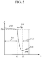
- FIG. 5 is a graph for describing another exemplary embodiment of the bioelectrical impedance measurement method.
- FIG. 5 illustrates an example of switch from the second measurement mode to the first measurement mode, wherein when second measurement mode measured in the second measurement mode is less than a second threshold, the measurement mode is switched from the second measurement mode to the first measurement mode.
- the second impedance may be set in consideration of a dynamic range of the apparatus 100 for measuring bioelectrical impedance.
- Reference numeral 510 in FIG. 5 denotes measurement impedance
- reference numeral 511 denotes a second measurement mode interval
- reference numeral 512 denotes a first measurement mode interval
- reference numeral 513 denotes a measurement mode switch interval.
- the voltmeter 120 measures a second voltage v(t) of the object in the second measurement mode, and the processor 140 monitors the measurement impedance (or second impedance Z2P(t) 510 ) based on the measured second voltage v(t) and determines time point t1 at which the measurement impedance (or second impedance Z2P(t) 510 ) becomes less than the second threshold Zth.
- the processor 140 extracts the second impedance Z 2p (t1) at the time point t1 and generates a second measurement mode switch signal at the time point t1.
- the measurement mode switcher 130 switches the measurement mode from the second measurement mode to the first measurement mode in response to the second measurement mode switch signal by opening the short-circuited first and third electrodes 101 and 103 and opening the short-circuited second and fourth electrodes 102 and 104 .
- the processor 140 monitors the measurement impedance 510 in the measurement mode switch interval 510 based on a voltage measured by the voltmeter 120 after the measurement mode switch to the first measurement mode starts, and the processor 140 determines the completion time t2 of the measurement mode switch. That is, the processor 140 monitors the measurement impedance 510 from the start time of the measurement mode switch, (e.g., the time point t1), and determines that the time point t2 at which the change of the measurement impedance 510 is turned from negative ( ⁇ ) to positive (+) is the completion time point of the measurement mode switch. As described with reference to FIG. 3 , the contact impedance decreases with time and accordingly, the first impedance of the first measurement mode increases. Therefore, the time point t2 at which the measurement impedance 510 in the measurement mode switch interval 513 starts increasing may be determined to be the completion time point of the measurement mode switch.
- the voltmeter 120 measures the first voltage v(t1) at the time point t2 in the first measurement mode, and the processor 140 obtains the first impedance Z4P(t2) based on the first voltage v(t2).
- the processor 140 obtains the bioelectrical impedance Z m of the object using Equation 4 based on the second impedance Z 2P (t1) and the first impedance Z4P(t2).
- FIG. 6 is a block diagram illustrating another exemplary embodiment of the apparatus for measuring bioelectrical impedance.
- an apparatus 600 for measuring bioelectrical impedance includes four electrodes, 601 , 602 , 603 , and 604 , a current source 610 , a voltmeter 620 , a measurement mode switcher 630 , a processor 640 , an analog-to-digital converter (ADC) 650 , and a controller 660 .
- the four electrodes 601 to 604 , the current source 610 , the voltmeter 620 , the measurement mode switcher 630 , and the processor 640 are the same as the four electrodes 101 to 104 , the current source 110 , the voltmeter 120 , the measurement mode switcher 130 , and the processor 140 of FIG. 1 , and thus detailed descriptions thereof will not be reiterated.
- the ADC 650 may convert a voltage, which is input as an analog signal, into a digital signal.
- the controller 660 may repeatedly perform calculation of bioelectrical impedance by controlling the current source 610 , the voltmeter 620 , the measurement mode switcher 630 , and the processor 640 .
- the controller 650 may control the current source 610 , the voltmeter 620 , the measurement mode switcher 630 , and the processor 640 such that measurement of a first voltage, calculation of first impedance, measurement mode switch, measurement of a second voltage, calculation of second impedance, and calculation of bioelectrical impedance are repeatedly performed until a difference between the most recently obtained bioelectrical impedance and bioelectrical impedance obtained immediately before said bioelectrical impedance becomes equal to or less than a predetermined threshold.
- the controller 650 may stop repeating the process and determine the last obtained bioelectrical impedance as the bioelectrical impedance of the object.
- FIG. 7 is a graph for describing another exemplary embodiment of the bioelectrical impedance measurement method.
- FIG. 7 shows an example in which measurement mode switch is performed when a predetermined period of time elapses in each measurement mode.
- the change of measurement impedance in a measurement mode switch interval is shown as a straight line in FIG. 7 for convenience of illustration.
- the voltmeter 620 measures a first voltage v(t1) of the object at time point t1 after a predetermined period of time elapses in the first measurement mode, and the processor 640 obtains first impedance Z 4P (t1) based on the first voltage v(t1).
- the processor 640 generates a first measurement mode switch signal at the time point t1, and the measurement mode switcher 630 switches the measurement mode from the first measurement mode to the second measurement mode by short-circuiting the first electrode 601 and the third electrode 603 to each other and short-circuiting the second electrode 602 and the fourth electrode 604 to each other.
- the processor 640 monitors measurement impedance in the measurement mode switch interval based on a voltage measured by the voltmeter 620 after the start of the measurement mode switch to the second measurement mode and determines the completion time t2 of the measurement mode switch. That is, the processor 640 monitors the measurement impedance in the measurement mode switch interval from the time point t1 and determines that the time point t2 at which the change of the measurement impedance is turned from positive (+) to negative ( ⁇ ) is the completion time point of the measurement mode switch.
- the voltmeter 620 measures a second voltage v(t2) of the object at the time point t2 in the second measurement mode, and the processor 640 obtains second impedance Z2P(t2) based on the second voltage v(t2).
- the processor 640 obtains the bioelectrical impedance Z m1 of the object using Equation 3 based on the first impedance Z 4P (t1) and the second impedance Z 2P (t2).
- the processor 640 generates a second measurement mode switch signal at a time point after a predetermined period of time elapses in the second measurement mode, under the control of the controller 660 , and the measurement mode switcher 630 switches the measurement mode from the second measurement mode to the first measurement mode by opening the short-circuited first and third electrodes 601 and 603 and the short-circuited second and fourth electrodes 602 and 604 in response to the second measurement mode switch signal.
- the voltmeter 620 measures a first voltage v(t3) of the object at time point t3 after a predetermined period of time elapses in the first measurement mode, and the processor 640 obtains first impedance Z 4P (t3) based on the first voltage v(t3).
- the processor 640 generates the first measurement mode switch signal at the time point t3, and the measurement mode switcher 630 switches the measurement mode from the first measurement mode to the second measurement mode by short-circuiting the first and third electrodes 601 and 603 to each other and short-circuiting the second and fourth electrodes 602 and 604 to each other in response to the first measurement mode switch signal.
- the processor 640 monitors measurement impedance in the measurement mode switch interval based on a voltage measured by the voltmeter 620 after the start of the measurement mode switch to the second measurement mode and determines the completion time t4 of the measurement mode switch. That is, the processor 640 monitors the measurement impedance in the measurement mode switch interval from the time point t3 and determines that the time point t4 at which the change of the measurement impedance is turned from positive (+) to negative ( ⁇ ) is the completion time point of the measurement mode switch.
- the voltmeter 640 measures a second voltage v(t4) of the object at the time point t4 in the second measurement mode, and the processor 640 obtains second impedance Z 2P (t4) based on the second voltage v(t4).
- the processor 640 obtains the bioelectrical impedance Z m2 of the object using Equation 3 based on the first impedance Z 2P (t3) and the second impedance Z 2P (t4).
- the controller 660 determines whether a difference between the bioelectrical impedance Z m2 and the bioelectrical impedance Z m1 is equal to or less than a predetermined threshold.
- the processor 640 When the difference between the bioelectrical impedance Z m2 and the bioelectrical impedance Z m1 is not equal to or less than the predetermined threshold, the processor 640 generates the second measurement mode switch signal at a time point after a predetermined period of time elapses in the second measurement mode, under the control of the controller 660 , and the measurement mode switcher 630 switches the measurement mode from the second measurement mode to the first measurement mode by opening the short-circuited first and third electrodes 601 and 603 and the short-circuited second and fourth electrodes 602 and 604 in response to the second measurement mode switch signal.
- the voltmeter 620 measures a first voltage v(t5) of the object at time point t5 after a predetermined period of time elapses in the first measurement mode, and the processor 640 obtains first impedance Z 4P (t5) based on the first voltage v(t5).
- the processor 640 generates a first measurement mode switch signal at the time point t5, and the measurement mode switcher 630 switches the measurement mode from the first measurement mode to the second measurement mode by short-circuiting the first and third electrodes 601 and 603 to each other and the second and fourth electrodes 602 and 604 to each other in response to the first measurement mode switch signal.
- the processor 640 monitors measurement impedance in the measurement mode switch interval based on a voltage measured by the voltmeter 620 after the start of the measurement mode switch to the second measurement mode and determines the completion time t6 of the measurement mode switch. That is, the processor 640 monitors the measurement impedance in the measurement mode switch interval from the time point t5 and determines that the time point t6 at which the change of the measurement impedance is turned from positive (+) to negative ( ⁇ ) is the completion time point of the measurement mode switch.
- the voltmeter 640 measures a second voltage v(t6) of the object at the time point t6 in the second measurement mode, and the processor 640 obtains second impedance Z 2P (t6) based on the second voltage v(t6).
- the processor 640 obtains the bioelectrical impedance Z m3 of the object using Equation 3 based on the first impedance Z 4P (t5) and the second impedance Z 2P (t6).
- the controller 660 determines whether a difference between the bioelectrical impedance Z m3 and the bioelectrical impedance Z m2 is equal to or less than a predetermined threshold. When the difference between the bioelectrical impedance Z m3 and the bioelectrical impedance Z m2 is equal to or less than the predetermined threshold, the controller 660 determines the bioelectrical impedance Z m3 as the bioelectrical impedance of the object.
- FIG. 8 is a flowchart illustrating an exemplary embodiment of a method of measuring bioelectrical impedance.
- the method of measuring bioelectrical impedance of FIG. 8 may be performed by the apparatus 100 for measuring bioelectrical impedance of FIG. 1 .
- the apparatus 100 for measuring bioelectrical impedance obtains first impedance immediately before the start of measurement mode switch from the first measurement mode to the second measurement mode (operation 810 ).
- the apparatus 100 may measure a first voltage of an object immediately before the start of measurement mode switch from the first measurement mode to the second measurement mode, wherein the first voltage of the object is applied to both ends of the third electrode 103 and the fourth electrode 104 due to a current applied to the object through the first and second electrodes 101 and 102 . Then, the apparatus 100 may obtain first impedance based on the first voltage measured immediately before the start of the measurement mode switch.
- the apparatus 100 switches the measurement mode from the first measurement mode to the second measurement mode (operation 820 ).
- the apparatus 100 may generate a first measurement mode switch signal by short-circuiting the first electrode 101 and the third electrode 103 to each other and short-circuiting the second electrode 102 and the fourth electrode 104 to each other when at least one of a condition that a predetermined period of time elapses in the first measurement mode and a condition that the first impedance exceeds a first threshold is satisfied.
- the apparatus 100 obtains second impedance immediately after the completion of the measurement mode switch from the first measurement mode to the second measurement mode (operation 830 ). For example, the apparatus 100 may determine the completion time point of the measurement mode switch from the first measurement mode to the second measurement mode, and measure a second voltage of the object immediately after the completion of the measurement mode switch, wherein the second voltage is applied to the third electrode 103 short-circuited to the first electrode 101 and the fourth electrode 104 short-circuited to the second electrode 102 due to the current applied to the object through the first electrode 101 short-circuited to the third electrode 103 and the second electrode 102 short-circuited to the fourth electrode 104 . Then, the apparatus 100 may obtain the second impedance immediately after the completion of the measurement mode switch based on the second voltage measured immediately after the completion of the measurement mode switch.
- the apparatus 100 may determine the completion time point of the measurement mode switch by monitoring the change of measurement impedance based on a voltage measured after the measurement mode switch starts. For example, the apparatus 100 may monitor the measurement impedance after the measurement mode switch starts, and determine a turning point of the sign of a differential value of the measurement impedance (e.g., the time point at which the change of the measurement impedance is turned from positive (+) to negative ( ⁇ )) as the completion time point of the measurement mode switch.
- a turning point of the sign of a differential value of the measurement impedance e.g., the time point at which the change of the measurement impedance is turned from positive (+) to negative ( ⁇ )
- the apparatus 100 obtains bioelectrical impedance of the object based on the first impedance immediately before the start of the measurement mode switch from the first measurement mode to the second measurement mode and the second impedance immediately after the completion of the measurement mode switch from the first measurement mode to the second measurement mode (operation 840 ).
- the apparatus 100 may obtain the bioelectrical impedance of the object using Equation 3 based on the first impedance immediately before the start of the measurement mode switch and the second impedance immediately after the completion of the measurement mode switch.
- FIG. 9 is a flowchart illustrating another exemplary embodiment of the method of measuring bioelectrical impedance.
- the method of measuring bioelectrical impedance of FIG. 9 may be performed by the apparatus for measuring bioelectrical impedance of FIG. 1 .
- the apparatus 100 monitors second impedance of the second measurement mode (operation 910 ).
- the apparatus 100 may measure a first voltage of the object which is applied to the third electrode 103 short-circuited to the first electrode 101 and the fourth electrode 104 short-circuited to the second electrode 102 due to a current applied to the object through the first electrode 101 short-circuited to the third electrode 103 and the second electrode 102 short-circuited to the fourth electrode 104 , and may monitor the second impedance of the second measurement mode based on the measured first voltage.
- the apparatus 100 determines whether the second impedance is less than a second threshold (operation 920 ). When the second impedance is equal to or greater than the second threshold, the apparatus 100 returns to operation 910 and monitors the second impedance of the second measurement mode.
- the apparatus 100 extracts the second impedance and determines that the extracted second impedance as second impedance immediately before start of the measurement mode switch (operation 930 ).
- the apparatus 100 switches the measurement mode from the second measurement mode to the first measurement mode (operation 940 ).
- the apparatus 100 may switch the measurement mode from the second measurement mode to the first measurement mode by opening the short-circuited first and third electrodes 101 and 103 and opening the short-circuited second and fourth electrodes 102 and 104 .
- the apparatus 100 obtains first impedance immediately after the completion of the measurement mode switch from the second measurement mode to the first measurement mode (operation 950 ). For example, the apparatus 100 may determine the completion time point of the measurement mode switch from the second measurement mode to the first measurement mode, and measure a first voltage of the object immediately after the measurement mode switch completes, wherein the first voltage is applied to the third electrode 103 and the fourth electrode 104 due to a current applied to the object through the first electrode 101 and the second electrode 102 . Then, the apparatus 100 may obtain the first impedance based on the first voltage measured immediately after the measurement mode switch completes.
- the apparatus 100 may determine the completion time point of the measurement mode switch by monitoring the change of measurement impedance based on a voltage measured after the measurement mode switch starts. For example, the apparatus 100 may monitor the measurement impedance after the measurement mode switch starts, and determine a turning point of the sign of a differential value of the measurement impedance (e.g., the time point at which the change of the measurement impedance is turned from negative ( ⁇ ) to positive (+)) as the completion time point of the measurement mode switch.
- a turning point of the sign of a differential value of the measurement impedance e.g., the time point at which the change of the measurement impedance is turned from negative ( ⁇ ) to positive (+)
- the apparatus 100 obtains bioelectrical impedance of the object based on the second impedance immediately before the start of the measurement mode switch from the second measurement mode to the first measurement mode and the first impedance immediately after the completion of the measurement mode switch from the second measurement mode to the first measurement mode (operation 960 ).
- the apparatus 100 may obtain the bioelectrical impedance of the object using Equation 4 based on the second impedance immediately before the start of the measurement mode switch and the first impedance immediately after the completion of the measurement mode switch.
- FIG. 10 is a flowchart illustrating an exemplary embodiment of a method of measuring bioelectrical impedance.
- the method of measuring bioelectrical impedance of FIG. 10 may be performed by the apparatus 600 for measuring bioelectrical impedance of FIG. 6 .
- the apparatus 600 obtains first impedance immediately before the start of measurement mode switch from the first measurement mode to the second measurement mode (operation 1010 ).
- the apparatus 600 may measure a first voltage of the object immediately before the start of measurement mode switch from the first measurement mode to the second measurement mode, wherein the first voltage of the object is applied to the third electrode 103 and the fourth electrode 104 due to a current applied to the object through the first electrode 101 and the second electrode 102 .
- the apparatus 600 may obtain the first impedance immediately before the start of the measurement mode switch based on the first voltage measured immediately before the start of the measurement mode switch.
- the apparatus 600 switches the measurement mode from the first measurement mode to the second measurement mode (operation 1020 ).
- the apparatus 600 may switch the measurement mode from the first measurement mode to the second measurement mode by short-circuiting the first electrode 101 and the third electrode 103 to each other and short-circuiting the second electrode 102 and the fourth electrode 104 to each other when at least one of a condition that a predetermined period of time elapses in the first measurement mode and a condition that the first impedance exceeds a first threshold is satisfied.
- the apparatus 600 obtains second impedance immediately after the completion of the measurement mode switch from the first measurement mode to the second measurement mode (operation 1030 ). For example, the apparatus 600 may determine the completion time point of the measurement mode switch from the first measurement mode to the second measurement mode and measure a second voltage of the object which is applied to the third electrode 103 short-circuited to the first electrode 101 and the fourth electrode 104 short-circuited to the second electrode 102 due to a current applied to the object through the first electrode 101 short-circuited to the third electrode 103 and the second electrode 102 short-circuited to the fourth electrode 104 . Then, the apparatus 600 may obtain the second impedance immediately after completion of the measurement mode switch, based on the second voltage of the object measured immediately after the completion of the measurement mode switch.
- the apparatus 600 may determine the completion time point of the measurement mode switch by monitoring the change of measurement impedance based on a voltage measured after the measurement mode switch starts. For example, the apparatus 600 may monitor the measurement impedance after the measurement mode switch starts, and determine a turning point of the sign of a differential value of the measurement impedance (e.g., the time point at which the change of the measurement impedance is turned from positive (+) to negative ( ⁇ )) as the completion time point of the measurement mode switch.
- a turning point of the sign of a differential value of the measurement impedance e.g., the time point at which the change of the measurement impedance is turned from positive (+) to negative ( ⁇ )
- the apparatus 600 obtains bioelectrical impedance of the object based on the first impedance immediately before the start of the measurement mode switch from the first measurement mode to the second measurement mode and based on the second impedance immediately after the completion of the measurement mode switch from the first measurement mode to the second measurement mode (operation 1040 ).
- the apparatus 600 may obtain the bioelectrical impedance of the object using Equation 3 based on the first impedance immediately before the start of the measurement mode switch and based on the second impedance immediately after the completion of the measurement mode switch.
- the apparatus 600 compares the most recently obtained bioelectrical impedance with bioelectrical impedance obtained immediately before the last bioelectrical impedance and determines whether a difference between the two bioelectrical impedances is equal to or less than a predetermined threshold (operation 1050 ).
- the apparatus 600 switches a measurement mode from the second measurement mode to the first measurement mode (operation 1060 ), and returns to operation 1010 to obtain the first impedance immediately before the start of the measurement mode switch from the first measurement mode to the second measurement mode. That is, the apparatus 600 repeatedly perform operations 1010 to 1060 until the difference between the most recently obtained bioelectrical impedance and the bioelectric impedance measured immediately before the last bioelectrical impedance becomes equal to or less than the predetermined threshold.
- the apparatus 600 determines the most recently obtained bioelectrical impedance as the bioelectrical impedance of the object and terminates the operation.
- FIG. 11 is a block diagram illustrating an exemplary embodiment of an apparatus for measuring biometric information.
- An apparatus 1100 for measuring biometric information may be mounted on an electronic device.
- the electronic device may include a mobile phone, a smartphone, a tablet computer, a notebook computer, a personal digital assistant (PDA), a portable multimedia player (PMP), a navigation system, an MP3 player, a digital camera, a wearable device, and the like.
- the wearable device may include various types, such as a wristwatch type, a wrist band type, a ring type, a belt type, a necklace type, an ankle band type, a thigh band type, a forearm band type, and the like.
- the electronic device and the wearable device are not limited to the aforementioned examples.
- the apparatus 100 for measuring biometric information includes a bioelectrical impedance measurer 1110 and a biometric information estimator 1120 .
- the bioelectrical impedance measurer 1110 which is a device capable of measuring bioelectrical impedance of an object is the same as the apparatuses 100 and 600 for measuring bioelectrical impedance described with reference to FIGS. 1 to 10 , and hence a detailed description thereof will not be reiterated.
- the biometric information estimator 1120 may estimate biometric information of the object based on the bioelectrical impedance of the object measured by the bioelectrical impedance measurer 1110 .
- the biometric information may include body fat percentage, body fat mass, muscle mass, skeletal muscle mass, basal metabolic rate, intracellular water content, extracellular water content, body water content, inorganic mass, visceral fat content and the like.
- the biometric information estimator 1120 may estimate biometric information of the object using a biometric information calculating formula.
- the biometric information calculating formula may define the relationship among biometric impedance, body information, and biometric information, and may be experimentally derived in advance.
- the body information may include sex, age, height, weight, and the like.
- FIG. 12 is a flowchart illustrating an exemplary embodiment of a method of measuring biometric information.
- the method of measuring biometric information of FIG. 12 may be performed by the apparatus 1100 for measuring biometric information of FIG. 11 .
- the apparatus 1100 for measuring biometric information measures bioelectrical impedance of an object (operation 1210 ).
- the apparatus 1100 estimates biometric information of the object based on the measured bioelectrical impedance (operation 1220 ).
- the biometric information may include body fat percentage, body fat mass, muscle mass, skeletal muscle mass, basal metabolic rate, intracellular water content, extracellular water content, body water content, inorganic mass, visceral fat content and the like.
- the apparatus 1100 may estimate the biometric information using a biometric information calculating formula.
- the biometric information calculating formula may define the relationship among biometric impedance, body information, and biometric information, and may be experimentally derived in advance.
- the body information may include sex, age, height, weight, and the like.
- FIG. 13A is a schematic view illustrating a comparison between measurement time in a related art bioelectric impedance measurement method and measurement time in a bioelectric impedance measurement method according to an exemplary embodiment.
- a measurement time of each mode is set to 3 seconds and a time interval of 1 second is set for mode switching between the first measurement mode and the second measurement mode.
- this is only an example and the disclosure is not limited thereto.
- the change of measurement impedance is schematically illustrated and the measurement mode switch interval is not clearly shown in FIG. 13A .
- the related art technique is disadvantageous in that the measurement time is lengthened since measurement is carried out twice by switching the measurement mode and a length of time for stabilizing the contact resistance is required in each measurement mode.
- the impedance measurement time may be shortened because time for stabilizing the contact impedance before measuring impedance is not required.
- the bio-impedance may be measured more quickly.
- FIG. 13B shows comparative data between measurement accuracy in a related art bioelectric impedance measurement method and a measurement accuracy in a bioelectric impedance measurement method according to an exemplary embodiment.
- the first impedance Z 4P (t) of the first measurement mode, the bioelectrical impedance Z m , and a body fat percentage are measured for twenty subjects by using a wrist type body fat scale measuring device.
- the measurement using a bio-impedance measurement method according to an exemplary embodiment e.g., corresponding to the measurement time of 5 S
- the measurement of the related art contact resistance compensation measurement method e.g., corresponding to the measurement time of 7 S
- the measurement time can be shortened (e.g., from 7 S to 5 S) while having the same measurement accuracy.
- the current embodiments can be implemented as computer readable codes in a computer readable record medium. Codes and code segments constituting the computer program can be easily inferred by a skilled person in the art.
- the computer readable record medium includes all types of record media in which computer readable data are stored. Examples of the computer readable record medium include a read only memory (ROM), a random access memory (RAM), a compact-disk (CD)-ROM, a magnetic tape, a floppy disk, and an optical data storage. Further, the record medium may be implemented in the form of a carrier wave such as Internet transmission. In addition, the computer readable record medium may be distributed to computer systems over a network, in which computer readable codes may be stored and executed in a distributed manner.
- At least one of the components, elements, modules or units represented by a block as illustrated in the drawings may be embodied as various numbers of hardware, software and/or firmware structures that execute respective functions described above, according to an embodiment.
- at least one of these components, elements or units may use a direct circuit structure, such as a memory, a processor, a logic circuit, a look-up table, etc. that may execute the respective functions through controls of one or more microprocessors or other control apparatuses.
- at least one of these components, elements or units may be specifically embodied by a module, a program, or a part of code, which contains one or more executable instructions for performing specified logic functions, and executed by one or more microprocessors or other control apparatuses.
- At least one of these components, elements or units may further include or be implemented by a processor such as a central processing unit (CPU) that performs the respective functions, a microprocessor, or the like.
- a processor such as a central processing unit (CPU) that performs the respective functions, a microprocessor, or the like.
- CPU central processing unit
- Two or more of these components, elements or units may be combined into one single component, element or unit which performs all operations or functions of the combined two or more components, elements of units.
- at least part of functions of at least one of these components, elements or units may be performed by another of these components, element or units.
- a bus is not illustrated in the above block diagrams, communication between the components, elements or units may be performed through the bus.
- Functional aspects of the embodiments may be implemented in algorithms that execute on one or more processors.
- the components, elements or units represented by a block or processing steps may employ any number of related art techniques for electronics configuration, signal processing and/or control, data processing and the like.
Abstract
Description
Z m =f 3(Z 4P(t1),Z 2P(t2)) where t2≈t1f or R c(t1)=R c(t2) (3)
Z m =f 3(Z 2P(t1),Z 4P(t2)) where t2≈t1 for R c(t1)=R c(t2) (4)
Claims (25)
Applications Claiming Priority (2)
| Application Number | Priority Date | Filing Date | Title |
|---|---|---|---|
| KR10-2017-0011232 | 2017-01-24 | ||
| KR1020170011232A KR20180087043A (en) | 2017-01-24 | 2017-01-24 | Apparatus and method for measuring bioelectric impedance, Apparatus and method for measuring biometric information |
Publications (2)
| Publication Number | Publication Date |
|---|---|
| US20180206761A1 US20180206761A1 (en) | 2018-07-26 |
| US10959641B2 true US10959641B2 (en) | 2021-03-30 |
Family
ID=61024653
Family Applications (1)
| Application Number | Title | Priority Date | Filing Date |
|---|---|---|---|
| US15/878,881 Active 2039-06-22 US10959641B2 (en) | 2017-01-24 | 2018-01-24 | Apparatus and method for measuring bioelectrical impedance and apparatus and method for measuring biometric information |
Country Status (4)
| Country | Link |
|---|---|
| US (1) | US10959641B2 (en) |
| EP (1) | EP3351169B1 (en) |
| KR (1) | KR20180087043A (en) |
| CN (1) | CN108338788B (en) |
Families Citing this family (6)
| Publication number | Priority date | Publication date | Assignee | Title |
|---|---|---|---|---|
| KR102636390B1 (en) * | 2018-10-31 | 2024-02-14 | 한국 한의학 연구원 | Method and device for diagnosing weakness using biological signals |
| KR20200052138A (en) * | 2018-11-06 | 2020-05-14 | 삼성전자주식회사 | Optical sensor, method for measuring optical signal, Apparatus for estimating blood concentration of analyte |
| CN109691993B (en) * | 2018-12-07 | 2022-07-26 | 芯海科技(深圳)股份有限公司 | Method for measuring heart rate variability and human body scale |
| KR20200078955A (en) * | 2018-12-24 | 2020-07-02 | 삼성전자주식회사 | An electronic device configured to correct an error of a bio-impedance value |
| US20220095946A1 (en) * | 2019-01-29 | 2022-03-31 | InBody Co., Ltd. | Bioimpedance measurement device and operation method thereof |
| CN117529277A (en) * | 2021-06-18 | 2024-02-06 | 三星电子株式会社 | Apparatus and method for human body impedance analysis insensitive to high contact impedance and parasitic effects |
Citations (18)
| Publication number | Priority date | Publication date | Assignee | Title |
|---|---|---|---|---|
| US6625487B2 (en) | 2001-07-17 | 2003-09-23 | Koninklijke Philips Electronics N.V. | Bioelectrical impedance ECG measurement and defibrillator implementing same |
| US20040054298A1 (en) | 2000-12-14 | 2004-03-18 | Yoshihisa Masuo | Body impedance measuring instrument |
| JP2006271745A (en) | 2005-03-30 | 2006-10-12 | Omron Healthcare Co Ltd | Body fat measuring apparatus |
| US7457660B2 (en) | 2002-11-27 | 2008-11-25 | Z-Tech (Canada) Inc. | Eliminating interface artifact errors in bioimpedance measurements |
| KR100885396B1 (en) | 2007-05-21 | 2009-02-24 | 주식회사 바이오스페이스 | Bioelectrical Impedance Analysis Apparatus |
| WO2010044026A1 (en) | 2008-10-16 | 2010-04-22 | Koninklijke Philips Electronics N.V. | Impedance measurement circuit and method |
| JP2011024831A (en) | 2009-07-27 | 2011-02-10 | Panasonic Electric Works Co Ltd | Body fat measurement device |
| US20110046505A1 (en) * | 2007-08-09 | 2011-02-24 | Impedimed Limited | Impedance measurement process |
| US20150150478A1 (en) * | 2012-12-05 | 2015-06-04 | Panasonic Intellectual Property Management Co. Ltd | Body composition measurement device, body composition measurement method, and correction method in body composition measurement |
| US20150157240A1 (en) * | 2013-12-06 | 2015-06-11 | General Electric Company | Electrical impedance imaging systems |
| US9084583B2 (en) | 2007-09-14 | 2015-07-21 | Medtronic Monitoring, Inc. | Medical device with automatic start-up upon contact to patient tissue |
| US20150201861A1 (en) * | 2014-01-21 | 2015-07-23 | Samsung Electronics Co., Ltd. | Apparatus and method of measuring bio impedance |
| US20150216441A1 (en) * | 2012-08-28 | 2015-08-06 | Impeto Medical | Electrophysiological analysis system |
| US20150342497A1 (en) * | 2013-01-09 | 2015-12-03 | Timpel S.A. | Method and apparatus for acquiring of signals for electrical impedance |
| US20150359452A1 (en) * | 2014-06-12 | 2015-12-17 | PhysioWave, Inc. | Impedance measurement devices, systems, and methods |
| US20160106337A1 (en) | 2014-10-21 | 2016-04-21 | Samsung Electronics Co., Ltd. | Apparatus for measuring body fat and method thereof |
| US20160220143A1 (en) | 2015-01-30 | 2016-08-04 | Samsung Electronics Co., Ltd. | Body composition measuring apparatus and method |
| EP3153099A1 (en) | 2015-10-07 | 2017-04-12 | Samsung Electronics Co., Ltd. | Apparatus and method of measuring bio signal |
Family Cites Families (6)
| Publication number | Priority date | Publication date | Assignee | Title |
|---|---|---|---|---|
| CN1455869A (en) * | 2000-08-30 | 2003-11-12 | 克利夫顿·劳伦斯 | Device to audibly express impedance difference |
| FR2830740B1 (en) * | 2001-10-12 | 2004-07-23 | Seb Sa | BODY COMPOSITION MEASURING APPARATUS |
| CN101194836B (en) * | 2006-12-05 | 2011-09-14 | 重庆博恩富克医疗设备有限公司 | Method and device for eliminating interference in bio-electrical impedance measurement |
| CN101889866B (en) * | 2010-07-30 | 2012-02-08 | 西安理工大学 | Palm bioelectrical impedance spectrum measuring device for biological characteristic recognition |
| JP2012210236A (en) * | 2011-03-30 | 2012-11-01 | Sony Corp | Measurement apparatus, measurement method, information processing apparatus, information processing method, and program |
| CN106066425B (en) * | 2016-07-29 | 2019-01-08 | 中国电子科技集团公司第四十一研究所 | A kind of impedance measurement device and its method for realizing compensation for calibrating errors |
-
2017
- 2017-01-24 KR KR1020170011232A patent/KR20180087043A/en unknown
-
2018
- 2018-01-24 CN CN201810070899.2A patent/CN108338788B/en active Active
- 2018-01-24 US US15/878,881 patent/US10959641B2/en active Active
- 2018-01-24 EP EP18153196.3A patent/EP3351169B1/en active Active
Patent Citations (27)
| Publication number | Priority date | Publication date | Assignee | Title |
|---|---|---|---|---|
| US20040054298A1 (en) | 2000-12-14 | 2004-03-18 | Yoshihisa Masuo | Body impedance measuring instrument |
| US20060094979A1 (en) | 2000-12-14 | 2006-05-04 | Art Haven 9 Co., Ltd. | Body impedance measurement apparatus |
| JP4101654B2 (en) | 2000-12-14 | 2008-06-18 | 株式会社フィジオン | Body impedance measuring device |
| US6625487B2 (en) | 2001-07-17 | 2003-09-23 | Koninklijke Philips Electronics N.V. | Bioelectrical impedance ECG measurement and defibrillator implementing same |
| US7457660B2 (en) | 2002-11-27 | 2008-11-25 | Z-Tech (Canada) Inc. | Eliminating interface artifact errors in bioimpedance measurements |
| JP2006271745A (en) | 2005-03-30 | 2006-10-12 | Omron Healthcare Co Ltd | Body fat measuring apparatus |
| US7813794B2 (en) | 2005-03-30 | 2010-10-12 | Omron Healthcare Co., Ltd. | Body fat measuring apparatus capable of measuring visceral fat with high accuracy |
| KR100885396B1 (en) | 2007-05-21 | 2009-02-24 | 주식회사 바이오스페이스 | Bioelectrical Impedance Analysis Apparatus |
| US20110046505A1 (en) * | 2007-08-09 | 2011-02-24 | Impedimed Limited | Impedance measurement process |
| US9084583B2 (en) | 2007-09-14 | 2015-07-21 | Medtronic Monitoring, Inc. | Medical device with automatic start-up upon contact to patient tissue |
| US8831898B2 (en) | 2008-10-16 | 2014-09-09 | Koninklijke Philips N.V. | Impedance measurement circuit and method |
| US20110208458A1 (en) * | 2008-10-16 | 2011-08-25 | Koninklijke Philips Electronics N.V. | Impedance measurement circuit and method |
| WO2010044026A1 (en) | 2008-10-16 | 2010-04-22 | Koninklijke Philips Electronics N.V. | Impedance measurement circuit and method |
| JP2011024831A (en) | 2009-07-27 | 2011-02-10 | Panasonic Electric Works Co Ltd | Body fat measurement device |
| US9078586B2 (en) | 2009-07-27 | 2015-07-14 | Panasonic Intellectual Property Management Co., Ltd. | Body fat measurement device |
| US20150216441A1 (en) * | 2012-08-28 | 2015-08-06 | Impeto Medical | Electrophysiological analysis system |
| US20150150478A1 (en) * | 2012-12-05 | 2015-06-04 | Panasonic Intellectual Property Management Co. Ltd | Body composition measurement device, body composition measurement method, and correction method in body composition measurement |
| US20150342497A1 (en) * | 2013-01-09 | 2015-12-03 | Timpel S.A. | Method and apparatus for acquiring of signals for electrical impedance |
| US20150157240A1 (en) * | 2013-12-06 | 2015-06-11 | General Electric Company | Electrical impedance imaging systems |
| US20150201861A1 (en) * | 2014-01-21 | 2015-07-23 | Samsung Electronics Co., Ltd. | Apparatus and method of measuring bio impedance |
| US20150359452A1 (en) * | 2014-06-12 | 2015-12-17 | PhysioWave, Inc. | Impedance measurement devices, systems, and methods |
| US20160106337A1 (en) | 2014-10-21 | 2016-04-21 | Samsung Electronics Co., Ltd. | Apparatus for measuring body fat and method thereof |
| EP3011901A1 (en) | 2014-10-21 | 2016-04-27 | Samsung Electronics Co., Ltd. | Apparatus for measuring body fat and method thereof |
| KR20160046616A (en) | 2014-10-21 | 2016-04-29 | 삼성전자주식회사 | Apparatus and method for measuring body fat |
| US20160220143A1 (en) | 2015-01-30 | 2016-08-04 | Samsung Electronics Co., Ltd. | Body composition measuring apparatus and method |
| EP3153099A1 (en) | 2015-10-07 | 2017-04-12 | Samsung Electronics Co., Ltd. | Apparatus and method of measuring bio signal |
| US20170100052A1 (en) | 2015-10-07 | 2017-04-13 | Samsung Electronics Co., Ltd. | Apparatus and method of measuring bio signal |
Non-Patent Citations (1)
| Title |
|---|
| Communication dated May 30, 2018, issued by the European Patent Office in counterpart European Patent Application No. 18153196.3. |
Also Published As
| Publication number | Publication date |
|---|---|
| KR20180087043A (en) | 2018-08-01 |
| EP3351169A1 (en) | 2018-07-25 |
| EP3351169B1 (en) | 2024-02-28 |
| CN108338788A (en) | 2018-07-31 |
| CN108338788B (en) | 2023-12-29 |
| US20180206761A1 (en) | 2018-07-26 |
Similar Documents
| Publication | Publication Date | Title |
|---|---|---|
| US10959641B2 (en) | Apparatus and method for measuring bioelectrical impedance and apparatus and method for measuring biometric information | |
| US11653850B2 (en) | Apparatus and method of measuring bio signal | |
| US11191487B2 (en) | Contact state estimating device, and biological signal measuring device | |
| KR20160036958A (en) | Apparatus for measuring a body composition and method for measuring a body composition using the same | |
| CN106691447B (en) | Muscle training aid device, muscle training evaluation device and method | |
| US8798726B2 (en) | Method and apparatus for eliminating motion artifacts of bio signal using personalized bio signal pattern | |
| US20220008020A1 (en) | Adaptive bio-signal feature combining apparatus and method | |
| Depari et al. | A wearable smartphone-based system for electrocardiogram acquisition | |
| KR20160120631A (en) | apparatus for measuring biological information | |
| US20230218209A1 (en) | Apparatus and method for analyzing in vivo component and impedance measuring apparatus | |
| KR20190008059A (en) | Bio-processor, bio-signal detecting system, and method for operating the same | |
| KR102539145B1 (en) | Apparatus and method for measuring bio signal | |
| Wang et al. | Evaluation of digital compressed sensing for real-time wireless ECG system with bluetooth low energy | |
| US20200107789A1 (en) | Apparatus and method for estimating blood pressure | |
| KR102569986B1 (en) | Adaptive bio-signal feature combining apparatus and method | |
| US20220233114A1 (en) | Apparatus and method for estimating oxygen saturation | |
| JP7440515B2 (en) | Systems and methods for calibrating dry electrode bioelectric impedance sensing | |
| US20210007666A1 (en) | Body water content measurement device, method, and program | |
| Megalingam et al. | Wheeled patient monitoring system | |
| US20210302345A1 (en) | Apparatus and method for analyzing biological material component, and apparatus for measuring impedance | |
| Sureshkumar et al. | UPASANA: Diagnostic toolkit for ASHA worker | |
| WO2023159223A1 (en) | Parallel adaptive motion artifact removal | |
| CZ37158U1 (en) | System for measuring the biometric parameters of an individual | |
| Lee | Improved confidence interval estimation for oscillometric blood pressure measurement by combining Bootstrap-After-Jackknife function with non-Gaussian models |
Legal Events
| Date | Code | Title | Description |
|---|---|---|---|
| FEPP | Fee payment procedure |
Free format text: ENTITY STATUS SET TO UNDISCOUNTED (ORIGINAL EVENT CODE: BIG.); ENTITY STATUS OF PATENT OWNER: LARGE ENTITY |
|
| AS | Assignment |
Owner name: SAMSUNG ELECTRONICS CO., LTD., KOREA, REPUBLIC OF Free format text: ASSIGNMENT OF ASSIGNORS INTEREST;ASSIGNORS:JUNG, MYOUNG HOON;NAMKOONG, KAK;LEE, YEOL HO;REEL/FRAME:045558/0257 Effective date: 20180125 |
|
| STPP | Information on status: patent application and granting procedure in general |
Free format text: DOCKETED NEW CASE - READY FOR EXAMINATION |
|
| STPP | Information on status: patent application and granting procedure in general |
Free format text: NON FINAL ACTION MAILED |
|
| STPP | Information on status: patent application and granting procedure in general |
Free format text: RESPONSE TO NON-FINAL OFFICE ACTION ENTERED AND FORWARDED TO EXAMINER |
|
| STPP | Information on status: patent application and granting procedure in general |
Free format text: NOTICE OF ALLOWANCE MAILED -- APPLICATION RECEIVED IN OFFICE OF PUBLICATIONS |
|
| STPP | Information on status: patent application and granting procedure in general |
Free format text: PUBLICATIONS -- ISSUE FEE PAYMENT VERIFIED |
|
| STCF | Information on status: patent grant |
Free format text: PATENTED CASE |