EP3553465B1 - Information processing device and information processing method - Google Patents
Information processing device and information processing method Download PDFInfo
- Publication number
- EP3553465B1 EP3553465B1 EP17879251.1A EP17879251A EP3553465B1 EP 3553465 B1 EP3553465 B1 EP 3553465B1 EP 17879251 A EP17879251 A EP 17879251A EP 3553465 B1 EP3553465 B1 EP 3553465B1
- Authority
- EP
- European Patent Office
- Prior art keywords
- target object
- image
- information processing
- search
- contour
- Prior art date
- Legal status (The legal status is an assumption and is not a legal conclusion. Google has not performed a legal analysis and makes no representation as to the accuracy of the status listed.)
- Active
Links
- 230000010365 information processing Effects 0.000 title claims description 72
- 238000003672 processing method Methods 0.000 title claims description 4
- 238000000034 method Methods 0.000 claims description 36
- 238000003384 imaging method Methods 0.000 claims description 31
- 239000003086 colorant Substances 0.000 claims description 21
- 230000005484 gravity Effects 0.000 claims description 21
- 230000008859 change Effects 0.000 claims description 10
- 230000006870 function Effects 0.000 claims description 6
- 238000004590 computer program Methods 0.000 claims description 2
- 238000001514 detection method Methods 0.000 description 21
- 238000012545 processing Methods 0.000 description 18
- 238000010586 diagram Methods 0.000 description 15
- 230000008569 process Effects 0.000 description 12
- 239000003550 marker Substances 0.000 description 8
- 238000013500 data storage Methods 0.000 description 7
- 238000005070 sampling Methods 0.000 description 7
- 238000011156 evaluation Methods 0.000 description 6
- 238000004891 communication Methods 0.000 description 5
- 238000006243 chemical reaction Methods 0.000 description 4
- 238000004364 calculation method Methods 0.000 description 3
- 239000000284 extract Substances 0.000 description 3
- 238000000605 extraction Methods 0.000 description 3
- 238000009877 rendering Methods 0.000 description 3
- 238000004458 analytical method Methods 0.000 description 2
- 230000000694 effects Effects 0.000 description 2
- 238000010191 image analysis Methods 0.000 description 2
- 238000005259 measurement Methods 0.000 description 2
- 230000003287 optical effect Effects 0.000 description 2
- 239000004065 semiconductor Substances 0.000 description 2
- 230000000007 visual effect Effects 0.000 description 2
- 230000001133 acceleration Effects 0.000 description 1
- 230000002411 adverse Effects 0.000 description 1
- 238000003491 array Methods 0.000 description 1
- 230000008901 benefit Effects 0.000 description 1
- 230000004397 blinking Effects 0.000 description 1
- 230000000295 complement effect Effects 0.000 description 1
- 238000012937 correction Methods 0.000 description 1
- 238000005516 engineering process Methods 0.000 description 1
- 238000013213 extrapolation Methods 0.000 description 1
- 238000001914 filtration Methods 0.000 description 1
- 230000014509 gene expression Effects 0.000 description 1
- 239000004973 liquid crystal related substance Substances 0.000 description 1
- 239000000463 material Substances 0.000 description 1
- 239000011159 matrix material Substances 0.000 description 1
- 230000007246 mechanism Effects 0.000 description 1
- 229910044991 metal oxide Inorganic materials 0.000 description 1
- 150000004706 metal oxides Chemical class 0.000 description 1
- 230000002093 peripheral effect Effects 0.000 description 1
- 238000011897 real-time detection Methods 0.000 description 1
- 239000011347 resin Substances 0.000 description 1
- 229920005989 resin Polymers 0.000 description 1
- 230000000717 retained effect Effects 0.000 description 1
- 230000035807 sensation Effects 0.000 description 1
- 230000003245 working effect Effects 0.000 description 1
Images


Classifications
-
- G—PHYSICS
- G06—COMPUTING; CALCULATING OR COUNTING
- G06T—IMAGE DATA PROCESSING OR GENERATION, IN GENERAL
- G06T7/00—Image analysis
- G06T7/70—Determining position or orientation of objects or cameras
- G06T7/73—Determining position or orientation of objects or cameras using feature-based methods
-
- G—PHYSICS
- G06—COMPUTING; CALCULATING OR COUNTING
- G06T—IMAGE DATA PROCESSING OR GENERATION, IN GENERAL
- G06T7/00—Image analysis
- G06T7/70—Determining position or orientation of objects or cameras
-
- G—PHYSICS
- G01—MEASURING; TESTING
- G01B—MEASURING LENGTH, THICKNESS OR SIMILAR LINEAR DIMENSIONS; MEASURING ANGLES; MEASURING AREAS; MEASURING IRREGULARITIES OF SURFACES OR CONTOURS
- G01B11/00—Measuring arrangements characterised by the use of optical techniques
- G01B11/24—Measuring arrangements characterised by the use of optical techniques for measuring contours or curvatures
-
- G—PHYSICS
- G01—MEASURING; TESTING
- G01B—MEASURING LENGTH, THICKNESS OR SIMILAR LINEAR DIMENSIONS; MEASURING ANGLES; MEASURING AREAS; MEASURING IRREGULARITIES OF SURFACES OR CONTOURS
- G01B11/00—Measuring arrangements characterised by the use of optical techniques
-
- G—PHYSICS
- G01—MEASURING; TESTING
- G01B—MEASURING LENGTH, THICKNESS OR SIMILAR LINEAR DIMENSIONS; MEASURING ANGLES; MEASURING AREAS; MEASURING IRREGULARITIES OF SURFACES OR CONTOURS
- G01B11/00—Measuring arrangements characterised by the use of optical techniques
- G01B11/02—Measuring arrangements characterised by the use of optical techniques for measuring length, width or thickness
-
- G—PHYSICS
- G01—MEASURING; TESTING
- G01C—MEASURING DISTANCES, LEVELS OR BEARINGS; SURVEYING; NAVIGATION; GYROSCOPIC INSTRUMENTS; PHOTOGRAMMETRY OR VIDEOGRAMMETRY
- G01C3/00—Measuring distances in line of sight; Optical rangefinders
- G01C3/02—Details
- G01C3/06—Use of electric means to obtain final indication
-
- G—PHYSICS
- G06—COMPUTING; CALCULATING OR COUNTING
- G06T—IMAGE DATA PROCESSING OR GENERATION, IN GENERAL
- G06T7/00—Image analysis
- G06T7/10—Segmentation; Edge detection
- G06T7/13—Edge detection
-
- G—PHYSICS
- G06—COMPUTING; CALCULATING OR COUNTING
- G06T—IMAGE DATA PROCESSING OR GENERATION, IN GENERAL
- G06T7/00—Image analysis
- G06T7/60—Analysis of geometric attributes
-
- G—PHYSICS
- G06—COMPUTING; CALCULATING OR COUNTING
- G06T—IMAGE DATA PROCESSING OR GENERATION, IN GENERAL
- G06T7/00—Image analysis
- G06T7/60—Analysis of geometric attributes
- G06T7/66—Analysis of geometric attributes of image moments or centre of gravity
-
- G—PHYSICS
- G06—COMPUTING; CALCULATING OR COUNTING
- G06T—IMAGE DATA PROCESSING OR GENERATION, IN GENERAL
- G06T2207/00—Indexing scheme for image analysis or image enhancement
- G06T2207/10—Image acquisition modality
- G06T2207/10004—Still image; Photographic image
- G06T2207/10012—Stereo images
Definitions
- the present invention relates to an information processing apparatus and an information processing method for identifying the position of a target object using a captured image.
- JP H08 178637 A relates to distance measurements by use of parallax detection, wherein a correlation matrix is computed.
- WO 2007/ 050885 A2 generally discloses a method for triggering commands of a program executed on a computing system.
- An interface object is defined by an object coupled to a handle. The interface object then is placed within a field of view of an image capture device, and a change in position of the interface object within the field of view of the image capture device triggers an interfacing command at the program executed on the computing system.
- An object of the invention is therefore to provide techniques for detecting the position of a target object highly accurately for information processing using captured images.
- the position information regarding the target object is acquired highly accurately using captured images.
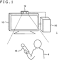
- FIG. 1 depicts a typical configuration of an information processing system embodying the present invention.
- This information processing system 1 includes a light-emitting device 18 to be held by a user 4, an imaging apparatus 12 that captures images of a space including the light-emitting device 18, an information processing apparatus 10 that identifies the position of the light-emitting device 18 and performs information processing on the basis of the identified device position, and a display apparatus 16 that outputs data generated as the result of the information processing.
- the information processing apparatus 10, imaging apparatus 12, and display apparatus 16 may be interconnected by cable or by any existing wireless communication technology such as Bluetooth (registered trademark).
- the external shapes of these apparatuses are not limited to those illustrated in the drawing. At least two of these apparatuses may be integrated into a single apparatus.
- the information processing apparatus 10, imaging apparatus 12, and display apparatus 16 may be integrally implemented as a mobile terminal furnished with the corresponding functions.
- the imaging apparatus 12 need not necessarily be mounted on the display apparatus 16. There may be multiple users 4 depending on what is processed by the information processing apparatus 10. There may also be multiple light-emitting devices 18.
- the imaging apparatus 12 has a camera that captures an image of the space including the light-emitting device 18 at a predetermined frame rate, and a mechanism that generates output data of the captured image by performing common processing such as demosaicing on an output signal from the camera before transmitting the generated output data to the information processing apparatus 10.
- the camera is equipped with common visible light sensors such as charge coupled device (CCD) sensors or complementary metal oxide semiconductor (CMOS) sensors.
- CCD charge coupled device
- CMOS complementary metal oxide semiconductor
- the stereo camera identifies the position of the target object such as the light-emitting device 18 in a three-dimensional space that includes the distance from an imaging plane of the camera to the target object.
- the imaging apparatus 12 may be a monocular camera.
- the imaging apparatus 12 may output to the information processing apparatus 10 a so-called raw image including a Bayer array acquired by visible light sensors so that the information processing apparatus 10 performs necessary processing such as demosaicing on the unmodified raw image.
- the information processing apparatus 10 identifies the position of the light-emitting device 18 in the real space using the data transmitted from the imaging apparatus 12. By carrying out necessary information processing based on the position information, the information processing apparatus 10 generates output data such as an image and a sound representing the result of the processing.
- the details of the processing performed by the information processing apparatus 10 using the position information regarding the light-emitting device 18 are not limited to anything specific. The processing details may thus be determined appropriately depending on the function desired by the user and on the details of the application in use. For example, the information processing apparatus 10 may acquire the movement of the user 4 from the movement of the light-emitting device 18 and permit progression of a game in which a character executing a similar movement appears. Also, the information processing apparatus 10 may convert the movement of the light-emitting device 18 into input commands and implement the function corresponding to the commands.
- the display apparatus 16 may be a TV set that includes a display for outputting display images and speakers for outputting sounds, such as a liquid crystal TV, an organic EL TV, a plasma TV, or a PC display.
- the display apparatus 16 may be a display and speakers included in a tablet terminal or in a mobile terminal.
- the display apparatus 16 may be a flat-screen display such as one depicted in the drawing, a head-mounted display that presents images before the eyes of the user wearing the head-mounted display, or a combination of both the flat-screen display and the head-mounted display.
- the information processing system 1 may further include an input apparatus that accepts, when operated by the user, requests for starting and ending processing and for selecting functions as well as the input of various commands, before supplying what is accepted as electrical signals to the information processing apparatus 10.
- the input apparatus may be any particular apparatus such as a controller, a mouse, or a joystick furnished with hardware keys, or a touch pad covering the display of the display apparatus 16.
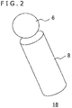
- FIG. 2 depicts a typical external shape of the light-emitting device 18.
- the light-emitting device 18 includes a light-emitting part 6 and a handle 8.
- the light-emitting part 6 is a sphere formed by a cover material such as a light-transmitting resin and incorporating a common light source such as a light-emitting diode or a light bulb.
- the entire spherical surface emits light when the device is turned on. In the case where multiple users use their individual light-emitting devices 18, these devices are configured to emit light in different colors for individual identification.
- the handle 8 is a part gripped by the user's hand and may be equipped with input buttons such as on/off buttons, not illustrated.
- the handle 8 may also include communication means establishing communication with the information processing apparatus 10 in wired or wireless fashion so as to exchange necessary information therewith.
- the information processing apparatus 10 may determine emitted-light colors allocated to multiple light-emitting devices, notify each light-emitting device 18 of the emitted-light color allotted thereto, and control light-emitting modes such as lighting and blinking of the devices.
- the handle 8 may incorporate motion sensors such as an acceleration sensor and a gyro sensor and have their measurements transmitted from the light-emitting device 18 to the information processing apparatus 10 at a predetermined rate. This allows the information processing apparatus 10 to identify the attitude of the light-emitting device 18 successively.
- the external shape of the light-emitting device 18 is not limited to what is depicted in the drawing.
- the light-emitting device 18 may be shaped to be worn on the user's body or formed integrally with the above-described head-mounted display or input apparatus.
- the surface of the head-mounted display or of the input device may include a light-emitting region of a predetermined shape. In this case, there may be one or multiple light-emitting regions on the surface.
- This embodiment extracts the image of the light-emitting part 6 highly accurately out of an image captured of a space in which diverse objects exist, and identifies the position of the light-emitting device 18 on the basis of the position and size of the light-emitting part 6.
- the image of the light-emitting part 6 is extracted as an approximately circular region.
- that source may be part of the input apparatus or head-mounted display of which the shape is not limited to anything specific.
- light emission from the light-emitting device 18 facilitates its distinction from the other objects within the field of view of the imaging apparatus 12, this is not limitative of this embodiment.
- the object whose position is to be detected need only be known in terms of color and shape and is not limited to a light-emitting object.
- the object such as the light-emitting device 18 of which the position in the real space is to be acquired on the basis of its captured image will be referred to as the "target object.”
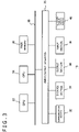
- FIG. 3 depicts an internal circuit configuration of the information processing apparatus 10.
- the information processing apparatus 10 includes a central processing unit (CPU) 22, a graphics processing unit (GPU) 24, and a main memory 26. These components are interconnected via a bus 30.
- the bus 30 is further connected with an input/output interface 28.
- the input/output interface 28 is connected with a communication section 32 that includes peripheral device interfaces such as USB and IEEE 1394 ports or a wired or wireless LAN network interface, a storage section 34 such as a hard disk drive or a nonvolatile memory, an output section 36 that outputs data to the display apparatus 16, an input section 38 that receives input of data from the imaging apparatus 12 and from the input apparatus, and a recording medium driving section 40 that drives removable recording media such as a magnetic disk, an optical disk, or a semiconductor memory.
- peripheral device interfaces such as USB and IEEE 1394 ports or a wired or wireless LAN network interface
- a storage section 34 such as a hard disk drive or a nonvolatile memory
- an output section 36 that outputs data to the display apparatus 16
- an input section 38 that receives input of data from the imaging apparatus 12 and from the input apparatus
- a recording medium driving section 40 that drives removable recording media such as a magnetic disk, an optical disk, or a semiconductor memory.
- the CPU 22 controls the entire information processing apparatus 10 by executing an operating system stored in the storage section 34. Also, the CPU 22 executes programs read from the removable recording media and loaded into the main memory 26 or various programs downloaded via the communication section 32.
- the GPU 24 having the functions of a geometry engine and a rendering processor carries out a rendering process in accordance with rendering instructions from the CPU 22 and stores a display image thus rendered into a frame buffer, not illustrated. The display image stored in the frame buffer is converted to a video signal that is output to the output section 36.
- the main memory 26 includes a random access memory (RAM) that stores programs and data necessary for processing.
- FIG. 4 depicts a functional block configuration of the information processing apparatus 10 embodying the present invention.
- the information processing apparatus 10 includes a captured image acquisition section 60 that acquires data of captured images from the imaging apparatus 12, a data storage section 62 that stores captured image data and position information data, a position information acquisition section 64 that acquires position information regarding the target object in the real space by detecting its image from the captured image, an information processing section 66 that performs predetermined information processing on the basis of the position information, and an output data generation section 68 that generates the data to be output as the result of the information processing.
- FIG. 4 The elements depicted in FIG. 4 as functional blocks for executing diverse processes may be constituted in terms of hardware by various circuits such as those of the CPU 22, GPU 24, and main memory 26 in FIG. 3 or implemented in terms of software by programs loaded from the recording medium driven by the recording medium driving section 40 or from the storage section 34 into the main memory 26. It is thus understood by those skilled in the art that these functional blocks may be diversely implemented, but not limited, by hardware only, by software only, or by a combination of both.
- the captured image acquisition section 60 successively acquires frame data of a moving image captured by the imaging apparatus 12 and stores the captured image into the data storage section 62. In the case where the frame image has yet to undergo a demosaicing process and shading compensation, the captured image acquisition section 60 performs such processing on the frame image before storing the image into the data storage section 62.
- the position information acquisition section 64 extracts an image of the target object out of the captured image read from the data storage section 62 and acquires the position information regarding the target object in the real space on the basis of the extracted image.
- the position information acquisition section 64 includes a target object detection section 70 that detects an approximate position of the target object image, a contour search section 72 that searches for a contour of the target object, and a position information generation section 74 that generates the position information regarding the target object in the three-dimensional space.
- the target object detection section 70 detects the image of the target object from the captured image on the basis of the emitted-light color and shape of the target object. For example, there may be prepared beforehand templates of possible shapes and colors of light-emitting marker images. Then a region having a high degree of similarity to one of the templates may be detected from the captured image.
- the detection process performed by the target object detection section 70 need only be sufficient to detect the approximate position of the target object image. That is, the means executing the process is not limited to anything specific.
- the contour search section 72 searches for the contour of the target object image based on the result of the detection performed by the target object detection section 70 in order to obtain the exact position of the target object.
- This embodiment obtains the position of the contour with high accuracy on a sub-pixel level, thereby improving both the accuracy of acquiring the position of the target object in the real space and the accuracy of information processing by use of the position information. Specific techniques for achieving these objectives will be discussed later.
- the position information generation section 74 acquires the position coordinates of the gravity center of the target object image and its size on the basis of the result of contour searches conducted by the contour search section 72. Using the gravity center position coordinates and the image size thus acquired, the position information generation section 74 identifies the position of the target object in the real space. In the case where the imaging apparatus 12 is a stereo camera, the position information generation section 74 obtains the position coordinates of the image gravity center of the same target object in each of stereoscopic images captured from right and left viewpoints. With the difference in the horizontal direction between the two image gravity centers used as a parallax, it is possible to acquire the distance from the imaging plane to the target object using the general principles of triangulation.
- the target object is a marker such as the light-emitting part 6 in FIG. 2 of which the apparent size remains unchanged regardless of angles, or where the target objects are multiple markers spaced a predetermined distance apart on the device surface
- a monocular camera may still be used to acquire the distance from the image size or from the marker-to-marker spacing.
- the position information generation section 74 identifies in this manner the distance from the imaging plane to the target object in the depth direction, represents that distance in terms of pixel values of the target object image as a region in the frame image to prepare a so-called depth map for position information digitalization for example, and stores the digitalized position information into the data storage section 62.
- the position information regarding the target objects is generated by obtaining, for example, the gravity center position of each of the target objects.
- the information processing section 66 reads the position information regarding the target object from the data storage section 62 and performs information processing accordingly. As mentioned above, the details of the information processing performed here are not limited to anything specific.
- the output data generation section 68 generates the data of the image to be displayed and the data of the sound to be output as the result of the information processing carried out by the information processing section 66.
- the output data generation section 68 outputs the generated data successively to the display apparatus 16.
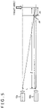
- FIG. 5 is an explanatory diagram explaining the relationship between a parallax between stereoscopic images captured from right and left viewpoints by a stereo camera used as the imaging apparatus 12 on the one hand, and the distance to the target object on the other hand.
- a first camera 13a and a second camera 13b are paired to constitute a stereo camera.
- the first camera 13a and the second camera 13b are installed to have their optical axes spaced a predetermined distance L apart in parallel with each other.
- the first camera 13a and the second camera 13b have their captured images corrected to achieve an appropriate field angle therebetween.
- the target object is assumed to be located in the arrowed rightmost position a distance Z apart in the depth direction.
- FIG. 6 depicts changes in the parallax D relative to the distance Z from the imaging apparatus 12.
- the parallax D plots a curve 56 in inverse proportion to the distance Z.
- the resolution of the distance Z to the target object drops in proportion to the distance Z squared.
- the spacing between vertical dotted lines in the graph in FIG. 6 represents ⁇ z.
- the distance Z is calculated as z1 or as z2 including an error of up to approximately ⁇ z. That is, the farther the target object is away from the imaging apparatus 12, the greater the adverse effect on the accuracy of distance calculation due to the error in acquiring the image position from the captured images.
- the contour search section 72 of this embodiment aims to improve the accuracy of acquiring the position information regarding the target object in the real space by obtaining the contour line of the image accurately on a sub-pixel level.
- FIG. 7 is an explanatory diagram explaining a method by which the contour search section 72 of this embodiment identifies the contour of the image of the target object.
- the target object detection section 70 extracts the region of a target object image 82 from a captured image 80 using a common method such as template matching or foreground extraction. The extraction process may be done in pixel units or in units of something larger to give precedence to efficiency.
- the contour search section 72 determines the start point of a search route and its direction in order to search for the contour position of the image.
- the contour search section 72 performs a search from inner side to outer side of the target object image and determines that a contour exists in the positions where luminance changes abruptly.
- a coordinate point 88 on the contour line is obtained by sampling pixel values from a start point 84 in the direction of an arrow 86.
- This search is performed in multiple directions to obtain multiple coordinate points on the contour line.
- FIG. 7 indicates the coordinate points thus obtained as hollow circles, they only represent position coordinates on the image plane and do not represent a captured image.
- the contour search section 72 approximates these multiple coordinate points using common techniques such as the least-square method to acquire the contour line of the target object image as a mathematical formula on the image plane.
- the target object is a spherical light-emitting marker
- its image appears circular.
- a contour line 94 of the image is obtained as a circle using the circular approximation method.
- the coordinate points are corrected using a common correction filter. If there exists any coordinate point having a large error deviating from an approximation formula, that point is excluded so that the coordinate points are made ultimately to converge on the approximation formula.
- a coordinate point 92 detected in a position hidden by the handle of the light-emitting device and thus deviating from the normal contour of the light-emitting marker is eliminated.
- the coordinate points to be removed can occur as a result of being hidden by some other object, or due to an error in coordinate point detection.
- the center coordinates C(x c , y c ) of a circle of the contour line 94 thus obtained represent the gravity center of the image of the light-emitting marker as the target object, with a radius R of the circle indicating the size of the image.
- the position information generation section 74 uses these pieces of data to obtain the position of the target object in the real space as described above. Incidentally, it is to be understood by those skilled in the art that the approximation of a set of coordinate points to lines and the acquisition of the gravity center and size of the target object image are accomplished by diverse techniques and that the shape of the target object is thus not limited to anything specific.
- the information regarding the target object may be set beforehand in order to ultimately determine its shape with the approximation line having the least error.
- the technique for obtaining the gravity center and size of the target object image is uniquely determined.
- the shape of the image obtained until up to the preceding frame of the captured moving image may be used as the basis for estimating the subsequent shape of the image, the estimated image being used for the approximation.
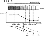
- FIG. 8 is an explanatory diagram explaining a method by which the embodiment detects the position of a contour line at a higher resolution than the resolution of pixels on the basis of changes in luminance in the direction of search. If the rightward direction in FIG. 8 is assumed to be the search direction, a pixel sequence 96 is formed by extracting pixels from the search route and by arraying the extracted pixels. Each of the pixels in the pixel sequence 96 has a luminance value. Where the changes in luminance between the pixels are represented as changes relative to their positions on the search route, these changes constitute a graph 98, for example.
- luminance values are obtained in pixel units.
- the graph 98 is formed by connecting discrete luminance values obtained with respect to positions x-2 ⁇ x, x- ⁇ x, x, x+ ⁇ x, x+2 ⁇ x, x+3 ⁇ x, etc.
- a previously prepared predictable luminance change curve is parallelly translated to form predictable curves such as curves 100a, 100b and 100c for comparison therebetween.
- the state in which the degree of similarity is highest between these curves is identified on the basis of the total sum of differences therebetween, for example.
- the reference position such as a midpoint M on the predictable curve 100b in that state is used as the position of the contour line of the target object. In FIG. 8 , that position is indicated by a hollow arrow.
- the predictable curve is translated in units smaller than the width ⁇ x of each pixel for a sort of the matching process. This allows the position of the contour line to be identified in units smaller than the pixel width.
- any detected point that includes a large error will result in a greater error in the position information regarding the target object in the real space the farther the target object is located, as was discussed above.
- the target object is 2 meters away from the imaging apparatus 12
- a deviation of only 0.5 pixels in the detected position of the gravity center leads to a deviation of approximately 3 centimeters of the distance calculated through stereo matching. This can lead to a motionless target object being erroneously recognized as in motion.
- FIG. 9 depicts an example of setting the directions of search.
- each rectangle in grid represents a pixel.
- Broken-line arrows denote the search routes and their directions.
- 24 searches are performed radially starting from one pixel in a pixel group 102 estimated to be near the center of the target object image identified approximately by the target object detection section 70. That is, as indicated by arrow groups 104a and 104b, three searches are made rightward and leftward starting from the pixel group 102 for a total of 6 searches. Also as indicated by arrow groups 106a and 106b, three searches are carried out upward and downward starting from the pixel group 102 for a total of 6 searches.
- the captured image targeted for analysis is generated by interpolating through a demosaicing process the raw image in which each pixel retains luminance data of one color.
- each of the pixels in the captured image generated in this manner includes an error stemming from the interpolation process. How the error is included varies from one pixel to another depending on the color targeted for observation with the corresponding element.
- FIG. 10 schematically depicts the relationship between the contour of the target object on the one hand and the color targeted for observation with the element corresponding to each pixel in the captured image on the other hand.
- each rectangle in grid represents a single pixel.
- the colors of red, green and blue targeted for observation with the corresponding elements are noted as "R,” “G” and "B,” respectively. Similar notations will also be used hereunder.
- the array of colors in the drawing is what is commonly called the Bayer array.
- the credibility of the detected coordinate points varies depending on the combination of such factors as the initial colors targeted for observation with the pixels on the search route, the change in luminance of a specific color for discriminating a coordinate point, and the colors of the target object.
- the pixels on the search route indicated by arrow A constitute a pattern of colors "R,” "B,” “R,” “B,” etc., for observation
- the pixels on the search route indicated by arrow B all have the color "G" for observation.
- the information regarding the color G on the search route indicated by arrow A includes an error due to interpolation.
- the result from the search route indicated by arrow B is more credible.
- detecting coordinate points using the changes in luminance of the color R or B causes the information regarding the color to develop an error on the route. That means the credibility is lower than if coordinate points are detected using the changes in luminance of the color G.
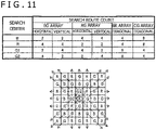
- FIG. 11 indicates search route counts given when search routes similar to those in FIG. 9 are grouped by the patterns of the colors targeted for observation with the pixels positioned on the routes.
- search routes are set in a manner centering on the color B as depicted in the lower subfigure in FIG. 11
- GG array having solely the color G repeated.
- the rate at which the color array appears varies depending on the search direction.
- the rate of appearance for the combination of the color array and the search direction varies depending on the color targeted for observation with the pixel at the search center.
- the rate of appearance varies depending on whether the pixel is either to the right or left of B, or above or below B.
- the former case is noted as “G1” and the latter case as “G2" as indicated in the lower subfigure.
- the credibility of the data in use varies from one search route to another.
- the methods of calculation such as the least-square method are based on the assumption that the initial data of interest is uniform in characteristics.
- the search center is determined for each frame based on the result of detection performed by the target object detection section 70, the results of calculating the gravity center position and size may well vary from one frame to another due to changes in the rate of dependence on the search center as depicted in FIG. 11 .
- this embodiment sets the search routes in such a manner that the error characteristics of coordinate points remain unchanged between search routes and between frames.
- FIG. 12 schematically depicts search routes used by the embodiment searching for the contour line of the target object.
- the embodiment performs searches starting from the pixels for observing the color G, the searches being limited to the diagonal directions in the pixel array. That is, searches are made from pixels set as the start points in a manner tracking pixels to observe the same color G in the top right, bottom right, bottom left, and top left directions.
- search routes used by the embodiment searching for the contour line of the target object.
- the embodiment performs searches starting from the pixels for observing the color G, the searches being limited to the diagonal directions in the pixel array. That is, searches are made from pixels set as the start points in a manner tracking pixels to observe the same color G in the top right, bottom right, bottom left, and top left directions.
- six start points may be established as indicated by hollow circles in FIG. 12 .
- duplication and skewed distribution of the search routes are averted by selecting as the start points those pixels of which the observation target is G and which are in the same sequence in the vertical or horizontal direction on the image plane as illustrated.
- the start points need only be positioned within an approximate region of the target object image detected by the target object detection section 70.
- the center of the start point sequence may be set near the gravity center of the region.
- the vertically closest G pixels e.g., every other pixel, are set as the start points.
- the start point spacing may be adjusted depending on the size of the target object image, for example.
- the number of searches may also be adjusted in accordance with the accuracy requirement and the processing performance of the apparatus in use.
- the gravity center of its image may be identified by conducting 24 searches as depicted in FIG. 12 with an error of approximately 0.016 pixels. Given the same number of searches, the accuracy of the target object position acquired in this manner is at least three times as high as in the case where searches are made in three directions, i.e., vertical, horizontal and diagonal, as depicted in FIG. 9 , to obtain coordinate points on the basis of the changes in luminance of each of the colors R, G and B.
- Using the search routes in FIG. 12 resolves the issues (1) and (2) above appropriately and at the same time. It is also possible to resolve the issue (1) alone by limiting the search routes to the diagonal directions. If the search start points are limited to R or to B, the pixels on the search routes still have a uniform color array targeted for observation, so that the error characteristics of the detected coordinate points are substantially uniform. As a result, the accuracy of approximating the contour line is made higher than in the case where the start point pixels are not limited.
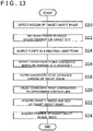
- FIG. 13 is a flowchart indicating processing steps in which the position information acquisition section 64 of the information processing apparatus 10 acquires the position information regarding the target object.
- the target object detection section 70 detects from the captured image the region of a target object image through template matching, for example (S10).
- the captured image used at this point is typically an RGB image having undergone demosaicing.
- the contour search section 72 determines as the search start points those pixels of which the observation target for the corresponding elements is G in the region (S12). In the example of FIG. 12 , every other pixel is selected in the vertical direction for a total of six start points. It is to be noted that the pixel-to-pixel spacing and the number of start points may be adjusted as needed.
- the information associating the pixels in the captured image with the colors for observation with the corresponding elements is acquired beforehand and retained internally by the contour search section 72. This is array information regarding arrays such as the Bayer array depicted in the captured image 112 in FIG. 10 for example.
- the relationship may be acquired through a calibration process that takes advantage of the detection result error being small. For example, an image is captured of the target object located a predetermined distance from the imaging apparatus 12. The search start point is then moved one pixel at a time up, down, right, and left for searches in the diagonal directions in order to obtain the contour line in each direction. The position of the target object is calculated under different search conditions. It is then determined that the start point with the smallest error is the position in which there exists a pixel whose observation target is G. When at least one such pixel is identified, it is possible to associate the pixels with the colors targeted for observation throughout the entire captured image on the basis of a repeating pattern such as the Bayer array.
- the contour search section 72 then performs searches in the four diagonal directions starting from the pixels determined as the start points so a to detect coordinate points on the contour line (S14 to S18). Specifically, the luminance values of the pixels on the search routes are sampled and stored into a line buffer (S14). In the example of FIG. 12 , the sampling is conducted in the four directions from the six start points for a total of 24 sampling sequences. Coordinate point candidates on the contour line are first detected on the basis of changes in luminance Y along each sampling sequence (S16). Specifically, as depicted in FIG. 8 , the predictable curve is positionally translated to determine the position in which the degree of similarity to a graph of changes in the luminance Y is the highest. That position is used as the coordinate point candidate.
- the luminance Y is the component of the luminance at the time each pixel value represented in the color space of YUV.
- the luminance Y is obtained from RGB data using a common conversion formula.
- the conversion may be performed after the RGB values are sampled in step S14.
- the conversion may be carried out on the entire captured image at the time the data of the captured image is acquired or is demosaiced, and a luminance image resulting from the conversion may be targeted for sampling.
- the luminance Y is targeted for evaluation at the time of coordinate point detection for two reasons: because the contribution ratio is highest for G with the smallest error on the search routes, and because the luminance includes information regarding R and B of nearby pixels due to interpolation. This makes it possible to take into consideration more information than if a single color is targeted, and enables implementation of the evaluation with high and uniform accuracy.
- the contour search section 72 then filters the coordinate point candidates detected in step S16 using the luminance changes in the color component of the target object, and excludes the coordinate points of low credibility (S18). For example, in the case where a marker that emits light in red is the target object, the evaluation is performed using the luminance of R. Where a marker that emits light in magenta is the target object, the evaluation is done using the luminance of the magenta component. If solely the changes in the luminance Y are targeted for the evaluation, coordinate points might be detected erroneously under the influence of the surrounding environment.
- the human eye easily distinguishes the target object but the apparatus may have difficulty in clearly identifying the boundary between the target object and the nearby light source given only the changes in the luminance Y.
- the process of detecting coordinate point candidates using the luminance Y and the process of excluding coordinate point candidates using the luminance of the color of the target object may be performed in different steps as illustrated, or may be carried out at the same time.
- the sampling sequence of the luminance Y on the search route and the sampling sequence of the luminance of the color of the target object are calculated in the same position so as to form a data sequence.
- This data sequence is matched against the predictable curve to identify coordinate points of high credibility.
- the contour search section 72 causes the distribution of the coordinate points to approximate the line of the predictable shape using the least-square method, thereby determining the contour of the target object image (S20) .
- the position information generation section 74 acquires the gravity center and size of the target object image based on the contour line thus identified (S22). Where the target object is a sphere as depicted in FIG. 7 , the contour line of the image forms a circular shape. Thus the center and radius of the circle are obtained. The position information generation section 74 then acquires the position information regarding the target object in the real space on the basis of the gravity center and size of the target object image (S24). In the case where the imaging apparatus 12 is a stereo camera, the processing of S10 to S22 is performed on each of the images captured from right and left viewpoints. The parallax between the gravity center positions then permits acquisition of the distance to the target object.
- the distance to the target object is acquired by comparing the actual size of the target object with the size of its image.
- the processing of S10 to S24 is performed on each of the target objects.
- changes over time in the position of the target object are obtained by repeating the processing of S10 to S24 on each of the frames of the moving image captured by the imaging apparatus 12 at a predetermined rate.
- the information processing section 66 performs information processing appropriately by identifying typically the position and movement of the user on the basis of the position information thus obtained regarding the target object.
- the contour of the target object image is detected by searching for luminance from within the image.
- a pixel of which the corresponding element targets G (green) for observing luminance is used as a start point from which searches are made in the four diagonal directions of the pixel array.
- the evaluation that additionally takes R (red) and B (blue) into account is made possible with emphasis on the luminance of G having a minimum of luminance error.
- coordinate point candidates are filtered using the changes in color luminance of the target object so as to improve the reliability of the coordinate points for use in approximation. This guarantees the robustness of the coordinate points being reliable against changes in ambient brightness.
- the present invention may be applied to information processing apparatuses such as game machines, image processing apparatuses and personal computers, as well as to information processing systems that include any one of these apparatuses.
Landscapes
- Physics & Mathematics (AREA)
- Engineering & Computer Science (AREA)
- General Physics & Mathematics (AREA)
- Computer Vision & Pattern Recognition (AREA)
- Theoretical Computer Science (AREA)
- Geometry (AREA)
- Electromagnetism (AREA)
- Radar, Positioning & Navigation (AREA)
- Remote Sensing (AREA)
- Image Analysis (AREA)
- Length Measuring Devices By Optical Means (AREA)
- Image Processing (AREA)
Applications Claiming Priority (2)
| Application Number | Priority Date | Filing Date | Title |
|---|---|---|---|
| JP2016238748A JP6602743B2 (ja) | 2016-12-08 | 2016-12-08 | 情報処理装置および情報処理方法 |
| PCT/JP2017/043334 WO2018105530A1 (ja) | 2016-12-08 | 2017-12-01 | 情報処理装置および情報処理方法 |
Publications (3)
| Publication Number | Publication Date |
|---|---|
| EP3553465A1 EP3553465A1 (en) | 2019-10-16 |
| EP3553465A4 EP3553465A4 (en) | 2020-07-29 |
| EP3553465B1 true EP3553465B1 (en) | 2022-06-22 |
Family
ID=62491006
Family Applications (1)
| Application Number | Title | Priority Date | Filing Date |
|---|---|---|---|
| EP17879251.1A Active EP3553465B1 (en) | 2016-12-08 | 2017-12-01 | Information processing device and information processing method |
Country Status (6)
| Country | Link |
|---|---|
| US (1) | US11282224B2 (zh) |
| EP (1) | EP3553465B1 (zh) |
| JP (1) | JP6602743B2 (zh) |
| KR (1) | KR102196845B1 (zh) |
| CN (1) | CN110036258B (zh) |
| WO (1) | WO2018105530A1 (zh) |
Families Citing this family (15)
| Publication number | Priority date | Publication date | Assignee | Title |
|---|---|---|---|---|
| US11762394B2 (en) | 2018-11-01 | 2023-09-19 | Nec Corporation | Position detection apparatus, position detection system, remote control apparatus, remote control system, position detection method, and program |
| JP6694039B1 (ja) * | 2018-11-22 | 2020-05-13 | 株式会社アイエンター | 魚体サイズ算出装置 |
| JP7280119B2 (ja) * | 2019-06-03 | 2023-05-23 | 古河電気工業株式会社 | 支援情報作成装置、支援情報作成システム、支援情報作成方法、及び支援情報作成プログラム |
| CN110378339B (zh) * | 2019-07-22 | 2021-08-17 | 海信视像科技股份有限公司 | 发光体的位置确定方法及装置 |
| CN110782492B (zh) * | 2019-10-08 | 2023-03-28 | 三星(中国)半导体有限公司 | 位姿跟踪方法及装置 |
| US11610330B2 (en) | 2019-10-08 | 2023-03-21 | Samsung Electronics Co., Ltd. | Method and apparatus with pose tracking |
| CN111981989A (zh) * | 2020-01-08 | 2020-11-24 | 杨春燕 | 电力线路现场宽度检测平台 |
| CN111242087A (zh) * | 2020-01-21 | 2020-06-05 | 华为技术有限公司 | 物体识别方法及装置 |
| CN111325220B (zh) * | 2020-02-17 | 2023-04-07 | 腾讯科技(深圳)有限公司 | 图像生成方法、装置、设备及存储介质 |
| EP3872693A1 (en) * | 2020-02-28 | 2021-09-01 | Aptiv Technologies Limited | Methods and systems for object detection |
| JP7392572B2 (ja) * | 2020-05-21 | 2023-12-06 | 富士通株式会社 | 画像処理装置、画像処理方法、及び画像処理プログラム |
| CN112215893B (zh) * | 2020-10-28 | 2022-10-28 | 安徽农业大学 | 目标二维中心坐标点确定方法、装置、设备及测距系统 |
| CN112668460A (zh) * | 2020-12-25 | 2021-04-16 | 北京百度网讯科技有限公司 | 目标检测方法、电子设备、路侧设备和云控平台 |
| CN113129280B (zh) * | 2021-04-09 | 2022-08-09 | 中国人民解放军63660部队 | 一种基于建筑物轮廓特征的目标落点测量方法 |
| CN115797876B (zh) * | 2023-02-08 | 2023-04-07 | 华至云链科技(苏州)有限公司 | 设备监控处理方法及系统 |
Family Cites Families (23)
| Publication number | Priority date | Publication date | Assignee | Title |
|---|---|---|---|---|
| JPH07121710A (ja) * | 1993-10-27 | 1995-05-12 | Hitachi Ltd | 画像セグメンテーション方法及び装置 |
| JP3235364B2 (ja) * | 1994-10-04 | 2001-12-04 | 株式会社明電舎 | 部品の姿勢検出装置 |
| JPH08178637A (ja) * | 1994-12-27 | 1996-07-12 | Mitsubishi Electric Corp | 画像処理装置及び画像処理方法 |
| JP3903360B2 (ja) * | 1999-06-28 | 2007-04-11 | パイオニア株式会社 | エッジ検出方法及びエッジ検出装置並びに画像符号化装置 |
| ES2391556T3 (es) * | 2002-05-03 | 2012-11-27 | Donnelly Corporation | Sistema de detección de objetos para vehículo |
| JP4269808B2 (ja) * | 2003-07-03 | 2009-05-27 | 株式会社ニコン | 色不良領域補正方法、色不良領域補正処理プログラム、色領域特定方法、色領域特定処理プログラムおよび画像処理装置 |
| JP2009514106A (ja) | 2005-10-26 | 2009-04-02 | 株式会社ソニー・コンピュータエンタテインメント | コンピュータプログラムとインタフェースするためのシステムおよび方法 |
| KR20080032746A (ko) * | 2006-10-10 | 2008-04-16 | 엠텍비젼 주식회사 | 움직임 인식 방법 및 그 장치 |
| US7929807B2 (en) | 2007-02-27 | 2011-04-19 | Phase One A/S | Colour binning of a digital image to reduce the image resolution |
| US7995840B2 (en) * | 2008-03-28 | 2011-08-09 | Seiko Epson Corporation | Image processing apparatus, image processing method, and program for attaining image processing |
| JP4852591B2 (ja) * | 2008-11-27 | 2012-01-11 | 富士フイルム株式会社 | 立体画像処理装置、方法及び記録媒体並びに立体撮像装置 |
| TWI422020B (zh) | 2008-12-08 | 2014-01-01 | Sony Corp | 固態成像裝置 |
| JP5158006B2 (ja) | 2009-04-23 | 2013-03-06 | ソニー株式会社 | 情報処理装置、および情報処理方法、並びにプログラム |
| JP5646263B2 (ja) * | 2010-09-27 | 2014-12-24 | 任天堂株式会社 | 画像処理プログラム、画像処理装置、画像処理システム、および、画像処理方法 |
| CN103035014A (zh) * | 2011-09-29 | 2013-04-10 | 索尼公司 | 图像处理设备和方法,以及成像设备和方法 |
| JP5953842B2 (ja) * | 2012-03-14 | 2016-07-20 | オムロン株式会社 | 画像検査方法および検査領域設定方法 |
| CN103839250B (zh) * | 2012-11-23 | 2017-03-01 | 诺基亚技术有限公司 | 用于面部图像处理的方法和设备 |
| JP5413501B1 (ja) * | 2012-12-07 | 2014-02-12 | 富士ゼロックス株式会社 | 画像処理装置、画像処理システム及びプログラム |
| CN105518702B (zh) * | 2014-11-12 | 2018-06-26 | 深圳市大疆创新科技有限公司 | 一种对目标物体的检测方法、检测装置以及机器人 |
| KR101660447B1 (ko) * | 2015-03-26 | 2016-09-28 | 인천대학교 산학협력단 | 베이어 패턴 컬러 필터 어레이 디모자이킹을 위한 다 방향 가중 보간 방법 |
| CN106067026B (zh) * | 2016-05-30 | 2020-01-31 | 天水师范学院 | 一种中药材显微图像的特征提取与识别检索方法 |
| CN106203398B (zh) | 2016-07-26 | 2019-08-13 | 东软集团股份有限公司 | 一种检测车道边界的方法、装置和设备 |
| KR101907451B1 (ko) * | 2017-05-19 | 2018-10-12 | 인천대학교 산학협력단 | 베이어 패턴 필터 기반 고해상도 컬러 영상 복원 및 화질 향상 장치 및 방법 |
-
2016
- 2016-12-08 JP JP2016238748A patent/JP6602743B2/ja active Active
-
2017
- 2017-12-01 KR KR1020197016547A patent/KR102196845B1/ko active IP Right Grant
- 2017-12-01 EP EP17879251.1A patent/EP3553465B1/en active Active
- 2017-12-01 US US16/344,155 patent/US11282224B2/en active Active
- 2017-12-01 WO PCT/JP2017/043334 patent/WO2018105530A1/ja unknown
- 2017-12-01 CN CN201780074482.7A patent/CN110036258B/zh active Active
Also Published As
| Publication number | Publication date |
|---|---|
| JP2018096716A (ja) | 2018-06-21 |
| KR102196845B1 (ko) | 2020-12-30 |
| KR20190082880A (ko) | 2019-07-10 |
| US11282224B2 (en) | 2022-03-22 |
| EP3553465A4 (en) | 2020-07-29 |
| US20200265601A1 (en) | 2020-08-20 |
| JP6602743B2 (ja) | 2019-11-06 |
| CN110036258A (zh) | 2019-07-19 |
| EP3553465A1 (en) | 2019-10-16 |
| CN110036258B (zh) | 2021-11-23 |
| WO2018105530A1 (ja) | 2018-06-14 |
Similar Documents
| Publication | Publication Date | Title |
|---|---|---|
| EP3553465B1 (en) | Information processing device and information processing method | |
| KR101761751B1 (ko) | 직접적인 기하학적 모델링이 행해지는 hmd 보정 | |
| JP6258953B2 (ja) | 単眼視覚slamのための高速初期化 | |
| KR101722654B1 (ko) | 점 특징 및 선 특징을 사용한 강력한 추적 | |
| CN111345029B (zh) | 一种目标追踪方法、装置、可移动平台及存储介质 | |
| CN110866977B (zh) | 增强现实处理方法及装置、系统、存储介质和电子设备 | |
| US9268408B2 (en) | Operating area determination method and system | |
| JP2021108193A (ja) | 画像処理装置、画像処理方法、及びプログラム | |
| KR20210067864A (ko) | 적응적 포커스 범위 및 계층화 스캐터링을 이용한 보케 이미지들의 생성 | |
| US11430178B2 (en) | Three-dimensional video processing | |
| JP6447521B2 (ja) | 情報処理装置、情報処理方法、およびプログラム | |
| US11030732B2 (en) | Information processing device, information processing system, and image processing method for generating a sum picture by adding pixel values of multiple pictures | |
| WO2024055531A1 (zh) | 照度计数值识别方法、电子设备及存储介质 | |
| KR20230097163A (ko) | 자동입체 텔레프레즌스 시스템들을 위한 3차원(3d) 얼굴 피처 추적 | |
| CN108921097B (zh) | 人眼视角检测方法、装置及计算机可读存储介质 | |
| CN111369612A (zh) | 一种三维点云图像生成方法及设备 | |
| TWI460683B (zh) | The way to track the immediate movement of the head | |
| US20240144530A1 (en) | Method, program, and system for 3d scanning | |
| WO2023281593A1 (ja) | 情報処理装置、制御方法及び記憶媒体 | |
| US11323682B2 (en) | Electronic device, content processing device, content processing system, image data output method, and image processing method | |
| CN117710445A (zh) | 一种应用于ar设备的目标定位方法、装置及电子设备 | |
| CN117768599A (zh) | 处理图像的方法、装置、系统、电子设备和存储介质 | |
| CN116485896A (zh) | 基于机器人的物体抓取方法、装置、机器人及存储介质 | |
| JPWO2019017360A1 (ja) | 線状物の3次元計測方法および装置 |
Legal Events
| Date | Code | Title | Description |
|---|---|---|---|
| STAA | Information on the status of an ep patent application or granted ep patent |
Free format text: STATUS: THE INTERNATIONAL PUBLICATION HAS BEEN MADE |
|
| PUAI | Public reference made under article 153(3) epc to a published international application that has entered the european phase |
Free format text: ORIGINAL CODE: 0009012 |
|
| STAA | Information on the status of an ep patent application or granted ep patent |
Free format text: STATUS: REQUEST FOR EXAMINATION WAS MADE |
|
| 17P | Request for examination filed |
Effective date: 20190509 |
|
| AK | Designated contracting states |
Kind code of ref document: A1 Designated state(s): AL AT BE BG CH CY CZ DE DK EE ES FI FR GB GR HR HU IE IS IT LI LT LU LV MC MK MT NL NO PL PT RO RS SE SI SK SM TR |
|
| AX | Request for extension of the european patent |
Extension state: BA ME |
|
| DAV | Request for validation of the european patent (deleted) | ||
| DAX | Request for extension of the european patent (deleted) | ||
| A4 | Supplementary search report drawn up and despatched |
Effective date: 20200629 |
|
| RIC1 | Information provided on ipc code assigned before grant |
Ipc: G06T 7/60 20170101ALI20200623BHEP Ipc: G01B 11/00 20060101ALI20200623BHEP Ipc: G01C 3/06 20060101ALI20200623BHEP Ipc: G06T 7/73 20170101AFI20200623BHEP Ipc: G01B 11/24 20060101ALI20200623BHEP |
|
| REG | Reference to a national code |
Ref country code: DE Ref legal event code: R079 Ref document number: 602017058868 Country of ref document: DE Free format text: PREVIOUS MAIN CLASS: G01B0011240000 Ipc: G06T0007730000 |
|
| RIC1 | Information provided on ipc code assigned before grant |
Ipc: G01C 3/06 20060101ALI20211222BHEP Ipc: G01B 11/24 20060101ALI20211222BHEP Ipc: G01B 11/00 20060101ALI20211222BHEP Ipc: G01B 11/02 20060101ALI20211222BHEP Ipc: G06T 7/60 20170101ALI20211222BHEP Ipc: G06T 7/73 20170101AFI20211222BHEP |
|
| GRAP | Despatch of communication of intention to grant a patent |
Free format text: ORIGINAL CODE: EPIDOSNIGR1 |
|
| STAA | Information on the status of an ep patent application or granted ep patent |
Free format text: STATUS: GRANT OF PATENT IS INTENDED |
|
| INTG | Intention to grant announced |
Effective date: 20220225 |
|
| GRAS | Grant fee paid |
Free format text: ORIGINAL CODE: EPIDOSNIGR3 |
|
| GRAA | (expected) grant |
Free format text: ORIGINAL CODE: 0009210 |
|
| STAA | Information on the status of an ep patent application or granted ep patent |
Free format text: STATUS: THE PATENT HAS BEEN GRANTED |
|
| AK | Designated contracting states |
Kind code of ref document: B1 Designated state(s): AL AT BE BG CH CY CZ DE DK EE ES FI FR GB GR HR HU IE IS IT LI LT LU LV MC MK MT NL NO PL PT RO RS SE SI SK SM TR |
|
| REG | Reference to a national code |
Ref country code: GB Ref legal event code: FG4D |
|
| REG | Reference to a national code |
Ref country code: CH Ref legal event code: EP |
|
| REG | Reference to a national code |
Ref country code: DE Ref legal event code: R096 Ref document number: 602017058868 Country of ref document: DE |
|
| REG | Reference to a national code |
Ref country code: AT Ref legal event code: REF Ref document number: 1500272 Country of ref document: AT Kind code of ref document: T Effective date: 20220715 |
|
| REG | Reference to a national code |
Ref country code: IE Ref legal event code: FG4D |
|
| REG | Reference to a national code |
Ref country code: LT Ref legal event code: MG9D |
|
| REG | Reference to a national code |
Ref country code: NL Ref legal event code: MP Effective date: 20220622 |
|
| PG25 | Lapsed in a contracting state [announced via postgrant information from national office to epo] |
Ref country code: SE Free format text: LAPSE BECAUSE OF FAILURE TO SUBMIT A TRANSLATION OF THE DESCRIPTION OR TO PAY THE FEE WITHIN THE PRESCRIBED TIME-LIMIT Effective date: 20220622 Ref country code: NO Free format text: LAPSE BECAUSE OF FAILURE TO SUBMIT A TRANSLATION OF THE DESCRIPTION OR TO PAY THE FEE WITHIN THE PRESCRIBED TIME-LIMIT Effective date: 20220922 Ref country code: LT Free format text: LAPSE BECAUSE OF FAILURE TO SUBMIT A TRANSLATION OF THE DESCRIPTION OR TO PAY THE FEE WITHIN THE PRESCRIBED TIME-LIMIT Effective date: 20220622 Ref country code: HR Free format text: LAPSE BECAUSE OF FAILURE TO SUBMIT A TRANSLATION OF THE DESCRIPTION OR TO PAY THE FEE WITHIN THE PRESCRIBED TIME-LIMIT Effective date: 20220622 Ref country code: GR Free format text: LAPSE BECAUSE OF FAILURE TO SUBMIT A TRANSLATION OF THE DESCRIPTION OR TO PAY THE FEE WITHIN THE PRESCRIBED TIME-LIMIT Effective date: 20220923 Ref country code: FI Free format text: LAPSE BECAUSE OF FAILURE TO SUBMIT A TRANSLATION OF THE DESCRIPTION OR TO PAY THE FEE WITHIN THE PRESCRIBED TIME-LIMIT Effective date: 20220622 Ref country code: BG Free format text: LAPSE BECAUSE OF FAILURE TO SUBMIT A TRANSLATION OF THE DESCRIPTION OR TO PAY THE FEE WITHIN THE PRESCRIBED TIME-LIMIT Effective date: 20220922 |
|
| REG | Reference to a national code |
Ref country code: AT Ref legal event code: MK05 Ref document number: 1500272 Country of ref document: AT Kind code of ref document: T Effective date: 20220622 |
|
| PG25 | Lapsed in a contracting state [announced via postgrant information from national office to epo] |
Ref country code: RS Free format text: LAPSE BECAUSE OF FAILURE TO SUBMIT A TRANSLATION OF THE DESCRIPTION OR TO PAY THE FEE WITHIN THE PRESCRIBED TIME-LIMIT Effective date: 20220622 Ref country code: LV Free format text: LAPSE BECAUSE OF FAILURE TO SUBMIT A TRANSLATION OF THE DESCRIPTION OR TO PAY THE FEE WITHIN THE PRESCRIBED TIME-LIMIT Effective date: 20220622 |
|
| PG25 | Lapsed in a contracting state [announced via postgrant information from national office to epo] |
Ref country code: NL Free format text: LAPSE BECAUSE OF FAILURE TO SUBMIT A TRANSLATION OF THE DESCRIPTION OR TO PAY THE FEE WITHIN THE PRESCRIBED TIME-LIMIT Effective date: 20220622 |
|
| PG25 | Lapsed in a contracting state [announced via postgrant information from national office to epo] |
Ref country code: SM Free format text: LAPSE BECAUSE OF FAILURE TO SUBMIT A TRANSLATION OF THE DESCRIPTION OR TO PAY THE FEE WITHIN THE PRESCRIBED TIME-LIMIT Effective date: 20220622 Ref country code: SK Free format text: LAPSE BECAUSE OF FAILURE TO SUBMIT A TRANSLATION OF THE DESCRIPTION OR TO PAY THE FEE WITHIN THE PRESCRIBED TIME-LIMIT Effective date: 20220622 Ref country code: RO Free format text: LAPSE BECAUSE OF FAILURE TO SUBMIT A TRANSLATION OF THE DESCRIPTION OR TO PAY THE FEE WITHIN THE PRESCRIBED TIME-LIMIT Effective date: 20220622 Ref country code: PT Free format text: LAPSE BECAUSE OF FAILURE TO SUBMIT A TRANSLATION OF THE DESCRIPTION OR TO PAY THE FEE WITHIN THE PRESCRIBED TIME-LIMIT Effective date: 20221024 Ref country code: ES Free format text: LAPSE BECAUSE OF FAILURE TO SUBMIT A TRANSLATION OF THE DESCRIPTION OR TO PAY THE FEE WITHIN THE PRESCRIBED TIME-LIMIT Effective date: 20220622 Ref country code: EE Free format text: LAPSE BECAUSE OF FAILURE TO SUBMIT A TRANSLATION OF THE DESCRIPTION OR TO PAY THE FEE WITHIN THE PRESCRIBED TIME-LIMIT Effective date: 20220622 Ref country code: CZ Free format text: LAPSE BECAUSE OF FAILURE TO SUBMIT A TRANSLATION OF THE DESCRIPTION OR TO PAY THE FEE WITHIN THE PRESCRIBED TIME-LIMIT Effective date: 20220622 Ref country code: AT Free format text: LAPSE BECAUSE OF FAILURE TO SUBMIT A TRANSLATION OF THE DESCRIPTION OR TO PAY THE FEE WITHIN THE PRESCRIBED TIME-LIMIT Effective date: 20220622 |
|
| PG25 | Lapsed in a contracting state [announced via postgrant information from national office to epo] |
Ref country code: PL Free format text: LAPSE BECAUSE OF FAILURE TO SUBMIT A TRANSLATION OF THE DESCRIPTION OR TO PAY THE FEE WITHIN THE PRESCRIBED TIME-LIMIT Effective date: 20220622 Ref country code: IS Free format text: LAPSE BECAUSE OF FAILURE TO SUBMIT A TRANSLATION OF THE DESCRIPTION OR TO PAY THE FEE WITHIN THE PRESCRIBED TIME-LIMIT Effective date: 20221022 |
|
| REG | Reference to a national code |
Ref country code: DE Ref legal event code: R097 Ref document number: 602017058868 Country of ref document: DE |
|
| PG25 | Lapsed in a contracting state [announced via postgrant information from national office to epo] |
Ref country code: AL Free format text: LAPSE BECAUSE OF FAILURE TO SUBMIT A TRANSLATION OF THE DESCRIPTION OR TO PAY THE FEE WITHIN THE PRESCRIBED TIME-LIMIT Effective date: 20220622 |
|
| PG25 | Lapsed in a contracting state [announced via postgrant information from national office to epo] |
Ref country code: DK Free format text: LAPSE BECAUSE OF FAILURE TO SUBMIT A TRANSLATION OF THE DESCRIPTION OR TO PAY THE FEE WITHIN THE PRESCRIBED TIME-LIMIT Effective date: 20220622 |
|
| PLBE | No opposition filed within time limit |
Free format text: ORIGINAL CODE: 0009261 |
|
| STAA | Information on the status of an ep patent application or granted ep patent |
Free format text: STATUS: NO OPPOSITION FILED WITHIN TIME LIMIT |
|
| 26N | No opposition filed |
Effective date: 20230323 |
|
| P01 | Opt-out of the competence of the unified patent court (upc) registered |
Effective date: 20230519 |
|
| P02 | Opt-out of the competence of the unified patent court (upc) changed |
Effective date: 20230528 |
|
| REG | Reference to a national code |
Ref country code: CH Ref legal event code: PL |
|
| REG | Reference to a national code |
Ref country code: BE Ref legal event code: MM Effective date: 20221231 |
|
| PG25 | Lapsed in a contracting state [announced via postgrant information from national office to epo] |
Ref country code: SI Free format text: LAPSE BECAUSE OF FAILURE TO SUBMIT A TRANSLATION OF THE DESCRIPTION OR TO PAY THE FEE WITHIN THE PRESCRIBED TIME-LIMIT Effective date: 20220622 Ref country code: LU Free format text: LAPSE BECAUSE OF NON-PAYMENT OF DUE FEES Effective date: 20221201 |
|
| PG25 | Lapsed in a contracting state [announced via postgrant information from national office to epo] |
Ref country code: LI Free format text: LAPSE BECAUSE OF NON-PAYMENT OF DUE FEES Effective date: 20221231 Ref country code: IE Free format text: LAPSE BECAUSE OF NON-PAYMENT OF DUE FEES Effective date: 20221201 Ref country code: CH Free format text: LAPSE BECAUSE OF NON-PAYMENT OF DUE FEES Effective date: 20221231 |
|
| PG25 | Lapsed in a contracting state [announced via postgrant information from national office to epo] |
Ref country code: BE Free format text: LAPSE BECAUSE OF NON-PAYMENT OF DUE FEES Effective date: 20221231 |
|
| PGFP | Annual fee paid to national office [announced via postgrant information from national office to epo] |
Ref country code: GB Payment date: 20231121 Year of fee payment: 7 |
|
| PG25 | Lapsed in a contracting state [announced via postgrant information from national office to epo] |
Ref country code: IT Free format text: LAPSE BECAUSE OF FAILURE TO SUBMIT A TRANSLATION OF THE DESCRIPTION OR TO PAY THE FEE WITHIN THE PRESCRIBED TIME-LIMIT Effective date: 20220622 |
|
| PGFP | Annual fee paid to national office [announced via postgrant information from national office to epo] |
Ref country code: FR Payment date: 20231122 Year of fee payment: 7 Ref country code: DE Payment date: 20231121 Year of fee payment: 7 |
|
| PG25 | Lapsed in a contracting state [announced via postgrant information from national office to epo] |
Ref country code: HU Free format text: LAPSE BECAUSE OF FAILURE TO SUBMIT A TRANSLATION OF THE DESCRIPTION OR TO PAY THE FEE WITHIN THE PRESCRIBED TIME-LIMIT; INVALID AB INITIO Effective date: 20171201 |
|
| PG25 | Lapsed in a contracting state [announced via postgrant information from national office to epo] |
Ref country code: CY Free format text: LAPSE BECAUSE OF FAILURE TO SUBMIT A TRANSLATION OF THE DESCRIPTION OR TO PAY THE FEE WITHIN THE PRESCRIBED TIME-LIMIT Effective date: 20220622 |