EP3553439B1 - Mécanisme d'étanchéité rotatif - Google Patents
Mécanisme d'étanchéité rotatif Download PDFInfo
- Publication number
- EP3553439B1 EP3553439B1 EP17881008.1A EP17881008A EP3553439B1 EP 3553439 B1 EP3553439 B1 EP 3553439B1 EP 17881008 A EP17881008 A EP 17881008A EP 3553439 B1 EP3553439 B1 EP 3553439B1
- Authority
- EP
- European Patent Office
- Prior art keywords
- sealing
- rotating body
- sealing assembly
- rotating
- disposed
- Prior art date
- Legal status (The legal status is an assumption and is not a legal conclusion. Google has not performed a legal analysis and makes no representation as to the accuracy of the status listed.)
- Active
Links
Images


Classifications
-
- F—MECHANICAL ENGINEERING; LIGHTING; HEATING; WEAPONS; BLASTING
- F27—FURNACES; KILNS; OVENS; RETORTS
- F27B—FURNACES, KILNS, OVENS OR RETORTS IN GENERAL; OPEN SINTERING OR LIKE APPARATUS
- F27B7/00—Rotary-drum furnaces, i.e. horizontal or slightly inclined
- F27B7/20—Details, accessories or equipment specially adapted for rotary-drum furnaces
- F27B7/22—Rotary drums; Supports therefor
- F27B7/24—Seals between rotary and stationary parts
-
- F—MECHANICAL ENGINEERING; LIGHTING; HEATING; WEAPONS; BLASTING
- F16—ENGINEERING ELEMENTS AND UNITS; GENERAL MEASURES FOR PRODUCING AND MAINTAINING EFFECTIVE FUNCTIONING OF MACHINES OR INSTALLATIONS; THERMAL INSULATION IN GENERAL
- F16J—PISTONS; CYLINDERS; SEALINGS
- F16J15/00—Sealings
- F16J15/16—Sealings between relatively-moving surfaces
- F16J15/32—Sealings between relatively-moving surfaces with elastic sealings, e.g. O-rings
- F16J15/3204—Sealings between relatively-moving surfaces with elastic sealings, e.g. O-rings with at least one lip
- F16J15/3232—Sealings between relatively-moving surfaces with elastic sealings, e.g. O-rings with at least one lip having two or more lips
-
- F—MECHANICAL ENGINEERING; LIGHTING; HEATING; WEAPONS; BLASTING
- F27—FURNACES; KILNS; OVENS; RETORTS
- F27D—DETAILS OR ACCESSORIES OF FURNACES, KILNS, OVENS OR RETORTS, IN SO FAR AS THEY ARE OF KINDS OCCURRING IN MORE THAN ONE KIND OF FURNACE
- F27D99/00—Subject matter not provided for in other groups of this subclass
- F27D99/0073—Seals
Definitions
- the present disclosure relates to the technical field of rotating seal mechanisms, and in particular to the technical field of sealing mechanisms for rotary kilns.
- Rotary kilns are widely used in the fields of building materials, metallurgy, chemical industry, environmental protection and the like, and can be divided into cement kilns, metallurgical chemical kilns, and lime kilns depending on different materials to be processed.
- the cement kiln is mainly used for calcining cement clinker;
- the metallurgical chemical kiln is used for magnetizing roasting of lean iron ore in iron and steel plants in metallurgical industry, oxidizing roasting of chromite and awaruite, roasting of high alumina bauxite in refractory material plants and roasting of clinker and aluminum hydroxide in aluminum plants, roasting of chrome ore sand and chrome ore powder in chemical plants, etc.
- the lime kiln is used for roasting active lime and light-burnt dolomite for use in iron and steel plants.
- the above-mentioned rotary kilns have a common feature that a process of heating materials is performed in such a manner that external fuel gas or a fuel such as coal or heavy oil contained in the materials themselves is combusted with air in the rotary kiln, the materials are directly heated, and some of the materials that need to be reduced are reduced by controlling the amount of air in the rotary kiln so that complete combustion does not take place in the rotary kiln so as to produce a reducing atmosphere such as carbon monoxide, but the concentration of carbon monoxide is relatively low, and leakage of air into the kiln or leakage of the reducing gas with relatively low concentration from the kiln has no major hazard to the safety of the rotary kiln.
- the above sealing methods can only be used to prevent leakage of a large amount of gas, do not have an ideal sealing effect, and can hardly guarantee that there is no pollution to the atmosphere, because dust and gases readily escape from the kiln body.
- external air inevitably enters the kiln, which causes an impure internal chemical reaction environment, affecting the effect of the reaction.
- the service life of the sealing mechanism is often greatly reduced due to the center displacement (bouncing movement) of the rotating body during the process of use.
- coal gas produced by coal or biomass pyrolysis contains a high amount of methane, carbon monoxide and hydrogen, and has a high calorific value.
- the sealing device sleeves a rotary kiln shell; a sealing structure is formed between a friction block and the rotary kiln shell; one end of the sealing device is connected to a kiln head cover or a kiln tail cover through a connecting plate; the sealing device comprises a connecting plate, a fixing plate, a front wedge block, a rear wedge block, a slide wheel frame, a slide wheel, a steel wire rope, a counter weight, and a friction block.
- the invented sealing device has the characteristics of a good sealing effect, a reliable structure, convenience in maintenance, and capabilities of preventing material leakage, protecting the environment and saving the energy resources, and solves the problems in the prior art such as invalid sealing of the kiln head or kiln tail due to axial shifting and radial displacement of the shell under heat, however there is a gap between the friction block and the rotary kiln shell and between the friction block and the friction block during movement, the sealing can still only guarantee that there is no large leakage, and the sealing between rigid parts still cannot guarantee no leakage of gas.
- JP2014040987A discloses a seal structure of rotary kilns and a rotary kiln
- US5571269A discloses a rotary seal assembly for rotary drum
- JP4256084B2 discloses a seal mechanism for a rotating body
- JP2003075069A discloses a seal structure for a rotary kiln
- CN102889783A discloses a sealing device and a rotary kiln
- CN105910427A discloses a sealing device for combined type rotary kilns
- JP2002005300A discloses a seal device for a rotating body.
- the present disclosure is directed to the deficiencies in the prior art to provide a rotating seal mechanism to completely solve the technical problem that the rotating seal is affected by the center displacement of the rotating body.
- a rotating seal mechanism for a rotary kiln is disposed between a fixed body and a rotating body and comprises: a sealing assembly (connector) disposed on a circumference of the rotating body and rotatably connected to the rotating body, wherein the sealing assembly comprises a sealing frame body, and the sealing frame body is provided therein with a sealing ring, a positioning ring for a sealing ring, and a gland for a sealing ring; a flexible connecting body (connector) connected with the sealing assembly and the fixed body; and a limiting cooperating component disposed on the sealing assembly.
- a follower (servo) support components are disposed on the sealing assembly, wherein the follower support components define the coaxiality between the sealing assembly and the rotating body, the follower support components are supporting rollers, supporting rings or supporting blocks respectively on one side of the sealing frame body and one side of the gland for the sealing ring, wherein during rotation of the rotating body, the sealing assembly moves relative to the rotating body to be radially displaced up and down and leftwards and rightwards with the rotating body, and during the rotation of the rotating body, the sealing member is subjected to friction from the rotating body, a force applied in a circumferential direction is unloaded onto the flexible connecting body, and a position of the sealing assembly in the circumferential direction changes.
- the sealing assembly is provided with a lubricating grease channel.
- a part of the fixed body is a shell (cylindrical body), wherein a diameter dimension of the shell is between a diameter dimension of the fixed body and a diameter dimension of the rotating body, the shell may be a part of the fixed body, and a dust-blocking heat insulation wall of labyrinth type is disposed between the shell and the rotating body.
- a part of the fixed body is a shell (cylindrical body), wherein a diameter dimension of the shell is between a diameter dimension of the fixed body and a diameter dimension of the rotating body, the shell may be a part of the fixed body, and a temperature-lowering box is disposed between the shell and the rotating body.
- a tyre is disposed between the sealing assembly and the rotating body, wherein a ring plate is disposed between the tyre and the rotating body on a side close to the flexible body and the ring plate is welded and sealed.
- a spiral blade is disposed between the rotating body and the tyre.
- the present disclosure is directed to the problems of untight sealing, poor sealing effect, and short service life of the sealing component caused by the center displacement of the rotating body that easily occur in the rotating seal, particularly in the rotating seal in medium and large-sized equipment, and the rotating seal between the rotating body and the fixed body is creatively decomposed, that is, the rotating seal is decomposed into a rotating seal between the rotating body and the sealing assembly, and a flexible displacement seal between the sealing assembly and the fixed body.
- the original complicated seal in which rotation, displacement, twisting, and slipping are combined together, is converted into a single rotating seal and a flexible seal in which multiple movements such as displacement, twisting, and slipping are converted into a flexible seal for absorbing flexible changes of the displacement, twisting and slipping; and both the seals can achieve complete sealing.
- a sealing assembly rotatably connected to the rotating body is disposed on the circumference of the rotating body, wherein the sealing assembly is brought into contact with the rotating body, and a good rotating seal between the sealing assembly and the rotating body is achieved while ensuring the contact between the sealing assembly and the rotating body.
- the sealing assembly is connected to the fixed body via a flexible connecting body.
- the flexible connecting body has its one end connected to the sealing assembly, and the other end connected to the fixed body. During the rotation of the rotating body, the sealing assembly moves relative to the rotating body, but is radially displaced up and down and leftwards and rightwards with the rotating body during its relative movement.
- the sealing assembly is connected to the fixed body via the flexible connecting body during the displacement.
- the flexible connecting body itself is soft and can undergo various deformations, in particular a deformation in a radial direction, thus a change in position of the sealing assembly will not be transmitted to the fixed body, so that the immovability of the fixed body and the displacement of the sealing assembly can be enabled to coexist for a long time without affecting each other. Frequent dynamic changes in position of the sealing assembly between an ideal axis and the actual dynamic axis are automatically absorbed by the flexible connecting body by its own flexibility.
- the flexible connecting body can ensure no mutual positional interference between the fixed body and the sealing assembly, but also can achieve reliable sealing between the sealing assembly and the fixed body.
- the decomposition of the rotating seal between the rotating body and the fixed body in the present disclosure i.e., the decomposition of the rotating seal into a rotating seal between the rotating body and the sealing assembly and a flexible displacement seal between the sealing assembly and the fixed body, is a design direction completely different from conventional designs performed by those skilled in the art.
- the rotating seal should be connected with a flexible connecting body for solving the problem of rotating seal between the rotating body and the fixed body during the displacement of the rotating body.
- the flexible connecting body can not only adapt to the problem of radial displacement of the sealing assembly during the center displacement of the rotating body, so that the sealing assembly displaces together with the rotating body in the radial direction to ensure the coaxiality between the sealing assembly and the rotating body and ensure that a pressure and deformation applied to the sealing member in the sealing assembly are within a normal range, thereby improving the sealing effect and the service life of the sealing member.
- the sealing member in the sealing assembly is subjected to friction from the rotating body, a force applied in the circumferential direction is unloaded onto the flexible body, and the position of the sealing assembly in the circumferential direction will also change.
- the sealing assembly may also be allowed to undergo a certain twisting change in the circumferential position.
- This frictional rotary force is finally unloaded on the fixed body via the flexible body to cause a twisting reaction force.
- the reaction force in turn limits the rotation of the sealing assembly within a small range via the flexible body.
- the flexible connecting body is used in a combination of radial displacement and circumferential rotation of the sealing assembly to allow the radial displacement of the sealing assembly and limits the circumferential rotation, and also achieves the seal between the sealing assembly and the fixed body, and is a key component in the dynamic rotating seal.
- the flexible connecting body and the follower support mechanism are matched combinations, which correspond to a relatively large center displacement of the rotating body, and a stable spacing between the sealing assembly and the rotating body, a relatively small frictional force, a normal deformation of the sealing member and a relatively good sealing effect, respectively. Only its relatively small frictional force can satisfy the radial change and the circumferential restraint of the sealing assembly by the flexible connecting body.
- the present disclosure provides a dynamic overall innovative system, and provides a technical achievement allowing mutual supporting between various components resulting from an innovative idea of rotating seal.
- the rotating seal mechanism of the present disclosure does not actually restrict the center displacement of the rotating body, and the center displacement of the rotating body is compensated by the flexible connecting body without affecting the sealing, so that transmission of the displacement to the fixed body is stopped, the sealing assembly is allowed to be displaced centrally with the rotating body, and the force of center displacement and the force of circumferential friction are effectively eliminated by the flexible connecting body.
- the magnitude of the center displacement of the rotating boy is unexpectedly gradually reduced, and slowly reaches a more controllable range.
- the speed is very fast, and even twice or more than twice as fast as a rotating body that is not liberated by the sealing component.
- the structure of the large or medium-sized rotating body is generally in the form of a metal structure, has a large volume, carries many materials therein, and is accompanied by a high-temperature chemical reaction process, thus it is unexpected that the large or medium-sized rotating body or rotary equipment rotating at high temperature with high load undergoes such a rapid deformation of the cylindrical shape during rotation, which is more advantageous to the rotation, results in a smaller center displacement, and is also more advantageous to sealing.
- the sealing assembly By disposing a circumferential (position) limiting cooperating component on the sealing assembly and disposing a (position) limiting component on the fixed body, the sealing assembly is displaced radially with the rotating body along a center line without moving circumferentially.
- the circumferential limiting component may be in various forms, each of which can enable the sealing assembly to be circumferentially immovable during the radial floating.
- the circumferential limiting component limits the circumferential direction of the sealing assembly. A rotational friction force generated by the sealing assembly during the rotation of the rotating body is directly unloaded on the fixed body, thereby avoiding the frictional resistance generated by the sealing assembly to be transmitted to the flexible connecting body, so that the flexible connecting body has a longer service life.
- the flexible connecting body may be adopted as a rubber product with a high flexibility, which can effectively guarantee deformation, oscillation (swing), and play of the flexible connecting body with the rotation of the rotary kiln.
- the complicated movement of the flexible connecting body compensates for the positional change between the fixed body and the rotating body, and solves the problem that the sealing assembly may generate a circumferential twisting force on the flexible connecting body during the rotating seal, so that the force applied to the flexible body is reduced as much as possible, and at the same time many problems generated in the rotating seal caused by the displacement of the rotating body are well solved.
- the circumferential limiting component is disposed on the fixed body, or may also be disposed on another fixed body, or even disposed in the flexible connecting body, as long as it can apply an action of force to the sealing assembly to prevent the circumferential movement thereof.
- a follower support mechanism is disposed on the sealing assembly.
- the coaxiality between the sealing assembly and the rotating body is defined by the follower support mechanism, so that there should be no large deviation between two rotation centers of the sealing member in the sealing assembly and the rotating body, thereby guaranteeing that the center of the sealing ring in the sealing assembly has no large deviation from the rotation center of the rotating body, whereby the distance between the sealing assembly and the periphery of the rotating body is more uniform, the normal sealing and gap compensating capability of the sealing ring is guaranteed.
- a proper gap is guaranteed between the follower support mechanism and the rotating body so that no sticking phenomenon occurs at a certain contact location, and at the same time the gap between the follower support mechanism and the rotating body should not be too large so as to ensure sealing.
- the sealing assembly cannot be guaranteed to be coaxial with the rotating body, the gap between the sealing assembly and the periphery of the rotating body may become severely uneven, the center of the sealing ring of the sealing assembly will be deviated too much from the center of the rotating body, and the sealing by the sealing ring may result in two phenomena at the same time.
- the sealing ring is severely deformed, and even the lip edge of the sealing ring is cracked by being pressed and is severely worn.
- the follower support mechanism may be implemented in various forms.
- a sliding or rolling mechanism is disposed on both sides of or in the middle of the sealing assembly, so that it is always guaranteed that there is always a circumferential relative movement between the sealing assembly and the rotating body, and the coaxiality between the sealing assembly and the rotating body is always ensured to be within a certain range. Because of the presence of the follower support mechanism, the sealing assembly is always displaced centrally with the rotating body in the radial direction of the rotating body.
- the sealing assembly comprises a sealing frame body, wherein the sealing frame body is provided therein with a sealing ring, a positioning ring for a sealing ring and a gland for a sealing ring.
- a flange is disposed between the fixed body and the flexible connecting body to facilitate installation of the equipment.
- a dust-blocking component is disposed in order to reduce entry of dust into a location between the sealing assembly and the rotating body, so as to reduce the wear of the sealing ring, and additionally can serve a good heat insulation function, and can reduce thermal radiation of the flexible connecting body and the sealing ring by the high temperature in the kiln to protect the flexible connecting body and the sealing ring.
- a temperature-lowering device is disposed between the shell and the rotating body to cool the gas entering the sealing zone, which is more advantageous to reducing the requirements for temperature resistance of materials of the flexible connecting body and the sealing ring, and improving the service life of the flexible connecting body and the sealing ring.
- a blocking ring is fixedly connected to the outer wall of the kiln head, it is appropriate that no friction will be generated between the blocking ring and the flange of the shell, and the blocking ring and the temperature-lowering device jointly serve for blocking dust and preventing thermal radiation.
- a tyre is disposed between the sealing assembly and the rotating body. Due to sliding friction between the sealing assembly and the rotating body, a portion of the rotating body that is brought into contact with the sealing assembly needs to be smoothed to reduce the friction and improve the sealing effect of the sealing assembly on the rotating body; however, there is great difficulty in local grinding and smoothing processes of a large-sized rotating body.
- a tyre is equivalent to a reduction of a dimension to be processed, the dimension of the tyre is smaller in volume than that of the rotating body, facilitating the processing of its surface and also facilitating installation, inspection and repair, and replacement, and at the same time the tyre can be used to distance the sealing assembly from the rotating body to reduce heat transmission from the rotating body outward to the sealing assembly so as to the improve the sealing performance and increase the service life of the sealing assembly.
- a ring plate is disposed between the tyre and the rotating body at one end where there is the flexible body and the ring plate is welded and sealed, the purpose of which is to guarantee that between the tyre and the rotating body there is no problem of gas leakage with inside the rotating body.
- the sealing ring, the positioning ring for the sealing ring and the sealing frame body of the sealing assembly are provided with a lubricating grease channel, which can conveniently achieve the injection of lubricating grease into the sealing ring to reduce the friction between the sealing ring and the tyre fixedly connected to the kiln head and prolong the service life of the sealing ring.
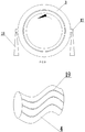
- the sealing ring is a Y-shaped or J-shaped sealing ring
- the Y-shaped or J-shaped sealing ring has the characteristic of large amount of dimension compensation, the compensation amount thereof mainly depends on a lip ring of the Y-shaped or J-shaped sealing ring, the lip ring has a relatively large elastic compensation capability, and there is no gap or aperture between the rubber and the tyre fixedly connected to the rotating body, and thus the sealing effect thereof is much higher than the sealing effect of a fish scale type seal or the like.
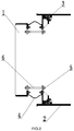
- a rotating seal mechanism is disposed between a fixed body 1 and a rotating body 2, wherein the diameter of the fixed body is larger than the diameter of the rotating body, and the fixed body and the rotating body can be regarded as a kiln head cover of a rotary kiln and a kiln body of the rotary kiln.
- the rotating seal mechanism comprises: a sealing assembly 3 disposed on an outer circumference of the rotating body 2 and rotatably connected to the rotating body 2, and a flexible connecting body 4 connected with the sealing assembly 3 and the fixed body 1; and the flexible connecting body 4 may be a high-temperature resistant rubber product or other products with good dimension compensation performance, which serves for reliable sealing and for compensation for a displacement.
- the sealing assembly 3 comprises a sealing frame body 7.
- the sealing frame body 7 is provided therein with a sealing ring 9, a positioning ring 8 for the sealing ring, and a gland 10 for the sealing ring.
- the sealing ring 9 is a J-shaped sealing ring, and a sealing lip of the J-shaped sealing ring is designed to have a large width in a diameter direction, and may have a width dimension of up to 10 to 20 mm, and may have a compensation capability of up to 5 to 10 mm on one side.
- the rubber sealing ring is made of silicone rubber or fluororubber or hydrogenated nitrile rubber (HNBR), and is resistant to a temperature of up to 250 °C.
- a circumferential limiting component includes a limiting cooperating component 5 disposed on the sealing frame body 7, and the limiting cooperating component 5 is a limiting orifice plate or a positioning stopper block or a positioning baffle; a limiting component 6 disposed on the fixed body 1 for restricting a circumferential rotation of the sealing assembly 3 is a supporting rod, one end of the limiting component 6 is fixed to the fixed body 1, and the other end of the limiting component 6 extends into the limiting orifice plate 5 which is the limiting cooperating component.
- the limiting orifice plate 5 has a certain space along the radial and circumferential directions of the rotating body, so that the limiting component 6 can be moved freely in the limiting orifice plate 5 in the radial direction of the rotating body during the rotation of the rotating body, whereas the space in the limiting orifice plate 5 along the circumferential direction of the rotating body is limited so as to only meet the requirement that the limiting component 6 and the limiting cooperating component 5 are not fully fixed, while preventing the limiting orifice plate 5 from moving in the circumferential direction, such that the sealing assembly 3 can be rotated radially with the rotating body 2, and displaced leftwards and rightwards and up and down along the center line without being rotated circumferentially.
- the second embodiment is different from the first embodiment only in that the sealing assembly 3 is provided with a follower support component 11 on both sides of the sealing frame body 7 and the gland 10 for the sealing ring.
- the follower support component 11 is a supporting roller, which supporting roller is made from a wear-resistant material and can roll on the outer circumference of the rotating body to ensure the requirement for coaxiality between the sealing assembly 3 and the rotating body 2 so as not to affect the sealing. A certain gap is provided between the follower support roller and the rotating body.
- This is intended to avoid that the rotating body and the follower support roller get stuck and cannot perform relative movement due to an absence of gap at a certain movement location because of a slight ellipse of the rotating body and a slight ellipse or deformation of the follower support roller, and on the other hand, this is intended to prevent a too large gap that causes a larger aperture between the sealing ring as well as the follower support roller and the rotating body and results in a phenomenon of gas leakage from a void, or to prevent a too small local gap that results in a phenomenon of cracking of the lip edge of the sealing ring upon being pressed.
- a rotating seal mechanism is disposed between a fixed body 1 and a rotating body 2, wherein the fixed body 1 is a kiln head cover of a rotary kiln, and the rotating body 2 is a kiln body of the rotary kiln.
- the rotating seal mechanism comprises: a sealing assembly 3 disposed on an outer circumference of the rotating body 2 and rotatably connected to the rotating body 2; and a flexible connecting body 4 connected with the sealing assembly 3 and the fixed body 1; and the flexible connecting body 4 may be a high-temperature resistant rubber product or other products with good dimension compensation performance, which serves for compensation for a displacement and for reliable sealing.
- the sealing assembly 3 comprises a sealing frame body 7.
- the sealing frame body 7 is provided therein with a sealing ring 9, a positioning ring 8 for the sealing ring, and a gland 10 for a sealing ring.
- the sealing ring 9 is a Y-shaped sealing ring, and a sealing lip of the Y-shaped sealing ring is designed to have a large width in a diameter direction, and may have a width dimension of up to 10 to 20 mm, and may have a compensation capability of up to 5 to 10 mm on one side.
- the rubber sealing ring is made of silicone rubber or fluororubber or hydrogenated nitrile rubber (HNBR), and is resistant to a temperature of up to 250 °C.
- the sealing assembly 3 is provided with a follower support component 11 on both sides of the sealing frame body 7 and the gland 10 for the sealing ring, wherein the follower support component 11 is a supporting ring or a supporting block, which supporting ring or supporting block is made of a wear-resistant material and can slide on the outer circumference of the rotating body.
- a limiting orifice plate 5 which is a limiting cooperating component is disposed on the sealing assembly 3
- a support frame 6 which is a limiting component for restricting a circumferential rotation of the sealing assembly 3 is disposed on the fixed body 1.
- the fixed body 1 is connected to the flexible connecting body 4 by a flange, and the other end of the flexible connecting body 4 is connected to the sealing frame body 7 by the flange.
- the limiting orifice plate 5 which is a limiting cooperating component is disposed on the flange of the sealing frame body.
- the support frame 6 which is a limiting component has one end disposed on the kiln head cover, and the other end extending into an end of the limiting cooperating component 5 to block the rotation of the limiting cooperating component 5.
- the limiting component 6 does not restrict the radial direction of the rotating body, so that the sealing assembly 3 is displaced radially along the center line with the rotating body 2 without moving circumferentially.
- a shell 12 is disposed between the fixed body and the flange connected thereto, wherein the diameter dimension of the shell 12 is between the diameter dimension of the fixed body 1 and the diameter dimension of the rotating body 2, this shell 12 is a part of the fixed body 1, and a dust-blocking heat insulation wall of labyrinth type 14 is disposed between the shell 12 and the rotating body 2.
- the dust-blocking heat insulation wall of labyrinth type 14 can prevent dust generated in the kiln from entering the sealing assembly and causing damage to the sealing assembly.
- the sealing assembly is provided with a lubricating grease channel 15.
- a tyre 16 is disposed between the sealing assembly 3 and the rotating body 2, a first purpose of which is to meet the need for reducing a frictional force, a second purpose of which is to meet the need for sealing, a third purpose of which is to meet the need for convenient processing, and a fourth purpose of which is to meet the need for convenient installation. That is, a smooth outer surface of the tyre can reduce the frictional force while improving the sealing performance between the sealing assembly and the tyre 16; and the contact portion is smoothed to reduce the friction and improve the sealing effect.
- the tyre 16 can be used to distance the sealing assembly 3 from the rotating body 2 to reduce heat transmission from the rotary kiln to the sealing location.
- the size of the tyre is smaller in volume than that of the rotating body, facilitating the processing of its surface.
- a ring plate 24 is disposed between the tyre 16 and the rotating body 2 at one end where there is the flexible body 4 and the ring plate is welded and sealed, the purpose of which is to guarantee that between the tyre and the rotating body there is no problem of gas leakage with inside the rotating body.
- a spiral blade 21 is disposed between the tyre 16 and the rotary kiln 2, so that the natural air cooling is forced along with the rotation of the rotary kiln to lower the temperature of the tyre 16 and avoid affecting the sealing and the service life of the sealing assembly due to a too high temperature of the surface of the tyre.
- a tyre 16 is disposed between the rotating body 2 and the sealing assembly 3, but also a ring plate 24 is disposed between the tyre 16 and the rotating body 2 at one end where there is the flexible body 4 and the ring plate is welded and sealed, the purpose of which is to guarantee that between the tyre and the rotating body there is no problem of gas leakage with inside the rotating body.
- a cooling nozzle 22 is disposed outside the tyre to spray water onto the aperture between the tyre and the rotary kiln for cooling.
- the fixed body 1 is a kiln head cover, a shell is disposed between the fixed body 1 and the flange connected thereto, and a temperature-lowering box 13 and a dust-blocking heat insulation wall 14 are provided as components between the shell and the rotating body 2.
- the function of providing the temperature-lowering box 13 is to effectively lower the high temperature in the rotary kiln at the temperature-lowering box to greatly reduce the heat transmission of radiant heat in the kiln to the flexible connecting body 4 and the sealing assembly 3, so that the flexible connecting body 4 and the sealing assembly 3 can have more extended service life; and the provision of the temperature-lowering box 13 and the dust-blocking wall 14 also serves for blocking dust.
- a rotating seal mechanism is disposed between the fixed body 1 and the rotating body 2 and comprises: a sealing assembly 3 disposed on an inner circumference of the rotating body 2 and rotatably connected to the rotating body 2; and a flexible connecting body 4 connected with the sealing assembly 3 and the fixed body 1; and the flexible connecting body 4 may be a high-temperature resistant rubber product or other products with good dimension compensation performance, which serves for compensation for a displacement and for reliable sealing.
- the sealing assembly 3 comprises a sealing frame body.
- the sealing frame body is provided therein with a sealing ring, a positioning ring for a sealing ring, and a gland for a sealing ring.
- the sealing ring 9 is a Y-shaped sealing ring, wherein a sealing lip of the Y-shaped sealing ring is designed to have a large width in a diameter direction, and may have a width dimension of up to 10 to 20 mm, and may have a compensation capability of up to 5 to 10 mm on one side.
- the rubber sealing ring is made of silicone rubber or fluororubber or hydrogenated nitrile rubber (HNBR), and is resistant to a temperature of up to 250 °C.
- the sealing assembly 3 is provided with a follower support component on both sides of the sealing frame body and the gland for the sealing ring, and the follower support component is a supporting ring or a supporting block, which supporting ring or supporting block is made of a wear-resistant material and can slide or roll on the inner circumference of the rotating body.
- a limiting cooperating component 5 is disposed on the sealing assembly 3, and a limiting component 6 for restricting a circumferential rotation of the sealing assembly 3 is disposed on the fixed body 1.
- the limiting component 6 has one end fixed to the fixed body, and the other end extending into an end of the limiting cooperating component 5.
- the limiting component 6 and the limiting cooperating component 5 are not fixedly connected to each other, the limiting component 6 does not restrict the radial movement of the cooperating component 5 with the rotating body, while only restricts the circumferential movement of the cooperating component 5 with the rotating body. Since the limiting cooperating component 5 is disposed on the sealing assembly 3, the sealing assembly 3 is displaced radially along the center line with the rotating body 2 without moving circumferentially.
- a dust-blocking component is disposed between the inner circumference of the flange and the rotating body, so that dust or gas generated in the kiln body can be prevented from escaping from the connecting component to protect the environment from pollution.
- the circumferential limiting component is disposed outside the fixed body and the rotating body, and can also achieve the function of circumferentially limiting the sealing assembly.
- a stopper block 17 is disposed on the sealing assembly 3
- a supporting rod 18 is disposed outside the fixed body externally to the rotating body, for example, on the ground below the sealing assembly, and the cooperation of the supporting rod 18 with the stopper block 17 can block a circumferential rotation of the sealing assembly 3 under the action of a circumferential frictional force, and at the same time can meet a radial movement of the sealing assembly 3 because a proper amount of gap is provided between them. Since the supporting rod is disposed below the sealing assembly, the supporting rod is in a good loaded state, and the supporting rod is firm and reliable.
- the circumferential limiting component is disposed in the flexible connecting body, and can also achieve the function of circumferentially limiting the sealing assembly.
- a metal strip 19 with suitable elasticity or other non-metallic material is disposed in the flexible connecting body 4, or a spring is also possible as long as it can enable or substantially enable the sealing assembly connected to one side of the flexible connecting body to be movable radially while substantially being immovable circumferentially.
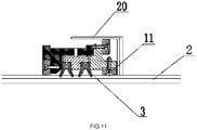
- the sealing assembly 3 includes not only a follower support component 11 disposed at a location brought into contact with the rotating body or the tyre to guarantee the normal operation of the sealing ring 9, but also a rolling frame 20 disposed on the rotating body or the tyre.
- the sealing assembly is disposed between the rolling frame 20 and the rotating body 2.
- the provision of a plurality of rolling components on the sealing assembly 3, in combination with the rolling frame 20, can ensure a suitable and assurable gap between the sealing assembly and the rotating body. Even the material of the flexible body itself has a certain ability to limit the circumferential rotation of the rotating body connected thereto, and the radial direction can be appropriately adjusted, by which the technical solution as claimed in the present disclosure can be implemented.
Landscapes
- Engineering & Computer Science (AREA)
- General Engineering & Computer Science (AREA)
- Mechanical Engineering (AREA)
- Muffle Furnaces And Rotary Kilns (AREA)
- Sealing With Elastic Sealing Lips (AREA)
- Sealing Devices (AREA)
Claims (6)
- Mécanisme de joint d'étanchéité rotatif pour un four rotatif, disposé entre un corps fixe (1) et un corps rotatif (2) et comprenant :un ensemble d'étanchéité (3) disposé sur une circonférence du corps rotatif (2) et raccordé, en rotation, au corps rotatif (2), dans lequel l'ensemble d'étanchéité (3) comprend un corps de bâti d'étanchéité (7) et le corps de bâti d'étanchéité (7) est doté, à l'intérieur de ce dernier, d'une bague d'étanchéité (9), d'une bague de positionnement (8) pour une bague d'étanchéité (9) et d'un presse-étoupe (10) pour une bague d'étanchéité (9) ;un corps de raccordement flexible (4) raccordé avec l'ensemble d'étanchéité (3) et le corps fixe (1) ;un composant de coopération de limitation (5) disposé sur l'ensemble d'étanchéité (3) ; etdes composants de support suiveurs (11) disposés sur l'ensemble d'étanchéité (3),caractérisé en ce que les composants de support suiveurs (11) définissent une coaxialité entre l'ensemble d'étanchéité (3) et le corps rotatif (2), les composants de support suiveurs (11) sont des rouleaux de support, des bagues de support ou des blocs de support respectivement sur un côté du corps de bâti d'étanchéité (7) et d'un côté du presse-étoupe (10) pour la bague d'étanchéité, dans lequel pendant la rotation du corps rotatif (2), l'ensemble d'étanchéité (3) se déplace par rapport au corps rotatif (2) pour être radialement déplacé vers le haut et vers le bas et vers la gauche et vers la droite avec le corps rotatif (2), et pendant la rotation du corps rotatif (2), l'élément d'étanchéité (3) est soumis à la friction du corps rotatif (2), une force appliquée dans une direction circonférentielle est déchargée sur le corps de raccordement flexible (4), et une position de l'ensemble d'étanchéité (3) dans la direction circonférentielle, change.
- Mécanisme de joint d'étanchéité rotatif selon la revendication 1, dans lequel l'ensemble d'étanchéité (3) est prévu avec un canal de graisse lubrifiante (15).
- Mécanisme de joint d'étanchéité rotatif selon l'une quelconque des revendications 1 à 2, dans lequel une partie du corps fixe (1) est une coque (12), une dimension de diamètre de la coque (12) est comprise entre une dimension de diamètre du corps fixe (1) et une dimension de diamètre du corps rotatif (2), et une paroi thermiquement isolante antipoussière (14) de type à labyrinthe est disposée entre la coque (12) et le corps rotatif (2).
- Mécanisme de joint d'étanchéité rotatif selon l'une quelconque des revendications 1 à 2, dans lequel une partie du corps fixe (1) est une coque (12), une dimension de diamètre de la coque (12) est comprise entre une dimension de diamètre du corps fixe (1) et une dimension de diamètre du corps rotatif (2), et une boîte d'abaissement de température (13) est disposée entre la coque (12) et le corps rotatif (2).
- Mécanisme de joint d'étanchéité rotatif selon l'une quelconque des revendications 1 à 4, dans lequel un bandage (16) est disposé entre l'ensemble d'étanchéité (3) et le corps rotatif (2).
- Mécanisme de joint d'étanchéité rotatif selon la revendication 5, dans lequel une aube en spirale (21) est disposée entre le corps rotatif (2) et le bandage (16).
Applications Claiming Priority (2)
| Application Number | Priority Date | Filing Date | Title |
|---|---|---|---|
| CN201611138458.9A CN106482506B (zh) | 2016-12-12 | 2016-12-12 | 旋转密封机构 |
| PCT/CN2017/085424 WO2018107662A1 (fr) | 2016-12-12 | 2017-05-23 | Mécanisme d'étanchéité rotatif |
Publications (3)
| Publication Number | Publication Date |
|---|---|
| EP3553439A4 EP3553439A4 (fr) | 2019-10-16 |
| EP3553439A1 EP3553439A1 (fr) | 2019-10-16 |
| EP3553439B1 true EP3553439B1 (fr) | 2020-07-29 |
Family
ID=58275189
Family Applications (1)
| Application Number | Title | Priority Date | Filing Date |
|---|---|---|---|
| EP17881008.1A Active EP3553439B1 (fr) | 2016-12-12 | 2017-05-23 | Mécanisme d'étanchéité rotatif |
Country Status (11)
| Country | Link |
|---|---|
| US (1) | US20190093949A1 (fr) |
| EP (1) | EP3553439B1 (fr) |
| JP (1) | JP6703640B2 (fr) |
| KR (1) | KR102057796B1 (fr) |
| CN (1) | CN106482506B (fr) |
| AU (1) | AU2017374531B2 (fr) |
| CA (1) | CA3021151C (fr) |
| RU (1) | RU2714756C1 (fr) |
| UA (1) | UA125751C2 (fr) |
| WO (1) | WO2018107662A1 (fr) |
| ZA (1) | ZA201807829B (fr) |
Families Citing this family (12)
| Publication number | Priority date | Publication date | Assignee | Title |
|---|---|---|---|---|
| CN106482506B (zh) * | 2016-12-12 | 2019-12-03 | 朱书红 | 旋转密封机构 |
| CN107143655B (zh) * | 2017-06-26 | 2019-05-17 | 农业部规划设计研究院 | 回转热解炉自动调紧浮动式动密封装置 |
| CN112484748A (zh) * | 2019-09-11 | 2021-03-12 | 九江精密测试技术研究所 | 一种温箱转台制冷输送系统密封结构 |
| CN111141143B (zh) * | 2020-01-21 | 2025-01-17 | 河南龙成煤高效技术应用有限公司 | 一种动态密封结构及回转窑设备 |
| KR102197370B1 (ko) * | 2020-04-29 | 2020-12-31 | 새마을환경개발주식회사 | 파쇄기능이 포함된 로더밀 동시 회전형 선별기 |
| CN111575030B (zh) * | 2020-05-27 | 2021-05-11 | 焦彪彪 | 一种具有可承重密封结构的生物质热解卧式转炉 |
| BR102020019375B1 (pt) * | 2020-09-24 | 2022-07-12 | Tecnored Desenvolvimento Tecnologico S.A. | Sistema de vedação autocompensador de dilatação térmica para um reator cilíndrico rotativo |
| CN112050625B (zh) * | 2020-09-29 | 2025-04-15 | 河南龙成煤高效技术应用有限公司 | 一种横式回转热解窑的密封结构 |
| CN113883888A (zh) * | 2021-11-12 | 2022-01-04 | 洛阳堆金环保设备有限公司 | 回转窑外装式节能焙烧系统 |
| KR102623663B1 (ko) | 2022-03-03 | 2024-01-11 | 주식회사 웅비기계 | 로터리 킬른 |
| JP7480250B1 (ja) * | 2022-10-20 | 2024-05-09 | 月島機械株式会社 | 回転シール冷却構造、加熱装置、および回転シール冷却方法 |
| CN119467706B (zh) * | 2024-11-14 | 2025-09-02 | 中铁工程装备集团有限公司 | 掘进机主驱动密封系统和掘进机 |
Family Cites Families (25)
| Publication number | Priority date | Publication date | Assignee | Title |
|---|---|---|---|---|
| SU43835A1 (ru) * | 1934-05-04 | 1935-07-31 | Г.П. Акафьев | Уплотнительное устройство дл примыкани барабана вращательной печи к кладке стены пылевой камеры |
| US2177441A (en) * | 1937-09-13 | 1939-10-24 | Achslager Syndikat | Oil and dust packing for rotating axles or shafts |
| US4199154A (en) * | 1976-07-28 | 1980-04-22 | Stauffer Chemical Company | Labyrinth sealing system |
| SU851056A1 (ru) * | 1979-04-04 | 1981-07-30 | Государственный Ордена Трудовогокрасного Знамени Всесоюзный Проектныйи Научно-Исследовательский Институтцементной Промышленности | Устройство дл уплотнени зазораМЕжду ВРАщАющЕйС пЕчью и НЕпОд-ВижНОй КАМЕРОй |
| SU1024673A1 (ru) * | 1982-02-15 | 1983-06-23 | Белгородский технологический институт строительных материалов им.И.А.Гришманова | Уплотнение вращающейс печи |
| HU201389B (en) * | 1987-07-10 | 1990-10-28 | Richter Gedeon Vegyeszet | Device for sealed leading axles of large deflection through the connecting branch of closed vessel |
| DE8714654U1 (de) * | 1987-11-04 | 1987-12-23 | Smit Ovens B.V., Nijmegen | Einrichtung zur Abdichtung eines Drehrohr- oder Drehherdofens |
| US5571269A (en) * | 1995-04-06 | 1996-11-05 | Buelow; Karl | Rotary seal assembly for rotary drum |
| JP2001304762A (ja) * | 2000-04-21 | 2001-10-31 | Meidensha Corp | 回転加熱処理装置 |
| JP4299954B2 (ja) * | 2000-06-19 | 2009-07-22 | 株式会社東芝 | 回転体シール装置 |
| JP3563048B2 (ja) * | 2001-06-29 | 2004-09-08 | 核燃料サイクル開発機構 | ロータリーキルンのシール構造 |
| JP4256084B2 (ja) * | 2001-07-13 | 2009-04-22 | 株式会社東芝 | 回転体シール機構 |
| JP4439146B2 (ja) * | 2001-08-29 | 2010-03-24 | メタウォーター株式会社 | ロータリキルンのシール構造 |
| JP4485321B2 (ja) * | 2004-11-01 | 2010-06-23 | 株式会社奈良機械製作所 | 回分式加熱炉 |
| JP2010127607A (ja) * | 2008-12-01 | 2010-06-10 | Nikko Co Ltd | ロータリーキルン |
| KR101273425B1 (ko) * | 2011-09-21 | 2013-06-11 | 한국에너지기술연구원 | 로터리킬른의 냉각 시일장치 |
| JP5997547B2 (ja) * | 2012-08-23 | 2016-09-28 | 高砂工業株式会社 | ロータリーキルンのシール構造およびロータリーキルン |
| CN102889783B (zh) * | 2012-11-06 | 2014-07-02 | 大唐国际发电股份有限公司 | 密封装置及回转窑 |
| CN103115364A (zh) * | 2013-02-05 | 2013-05-22 | 上海凯鸿环保工程有限公司 | 转窑密封系统 |
| CN204329586U (zh) * | 2014-11-19 | 2015-05-13 | 徒雨龙 | 回转炉的v型密封圈密封结构 |
| CN204495045U (zh) * | 2015-02-11 | 2015-07-22 | 张诗山 | 新型熟料窑密封装置 |
| CN105910427B (zh) * | 2016-05-05 | 2018-01-26 | 中信重工机械股份有限公司 | 一种复合式回转窑密封装置 |
| CN105928362B (zh) * | 2016-07-08 | 2018-10-30 | 中国重型机械研究院股份公司 | 一种粉煤热解窑多层复合密封装置 |
| CN206496639U (zh) * | 2016-12-12 | 2017-09-15 | 朱书红 | 旋转密封机构 |
| CN106482506B (zh) * | 2016-12-12 | 2019-12-03 | 朱书红 | 旋转密封机构 |
-
2016
- 2016-12-12 CN CN201611138458.9A patent/CN106482506B/zh active Active
-
2017
- 2017-05-23 KR KR1020187027959A patent/KR102057796B1/ko active Active
- 2017-05-23 RU RU2019101092A patent/RU2714756C1/ru active
- 2017-05-23 EP EP17881008.1A patent/EP3553439B1/fr active Active
- 2017-05-23 WO PCT/CN2017/085424 patent/WO2018107662A1/fr not_active Ceased
- 2017-05-23 UA UAA201900770A patent/UA125751C2/uk unknown
- 2017-05-23 CA CA3021151A patent/CA3021151C/fr active Active
- 2017-05-23 JP JP2019502136A patent/JP6703640B2/ja active Active
- 2017-05-23 AU AU2017374531A patent/AU2017374531B2/en active Active
-
2018
- 2018-11-20 ZA ZA2018/07829A patent/ZA201807829B/en unknown
- 2018-11-21 US US16/198,392 patent/US20190093949A1/en not_active Abandoned
Non-Patent Citations (1)
| Title |
|---|
| None * |
Also Published As
| Publication number | Publication date |
|---|---|
| KR102057796B1 (ko) | 2020-01-22 |
| CA3021151C (fr) | 2020-05-12 |
| KR20180117670A (ko) | 2018-10-29 |
| AU2017374531B2 (en) | 2019-09-26 |
| CA3021151A1 (fr) | 2018-06-21 |
| EP3553439A4 (fr) | 2019-10-16 |
| CN106482506A (zh) | 2017-03-08 |
| US20190093949A1 (en) | 2019-03-28 |
| RU2714756C1 (ru) | 2020-02-19 |
| ZA201807829B (en) | 2019-08-28 |
| AU2017374531A1 (en) | 2018-11-08 |
| UA125751C2 (uk) | 2022-06-01 |
| EP3553439A1 (fr) | 2019-10-16 |
| JP2019510949A (ja) | 2019-04-18 |
| JP6703640B2 (ja) | 2020-06-03 |
| WO2018107662A1 (fr) | 2018-06-21 |
| CN106482506B (zh) | 2019-12-03 |
Similar Documents
| Publication | Publication Date | Title |
|---|---|---|
| EP3553439B1 (fr) | Mécanisme d'étanchéité rotatif | |
| US4199154A (en) | Labyrinth sealing system | |
| JP6550648B2 (ja) | 円筒回転体シール装置 | |
| CN207161717U (zh) | 一种自动调节式迷宫密封装置及设置其的回转反应装置 | |
| CN103603955A (zh) | 一种回转炉的动密封连接装置 | |
| US3383115A (en) | Gas seal for furnaces | |
| US4457520A (en) | Device for sealing the gap between a rotary kiln and an inlet housing | |
| CN202329084U (zh) | 一种回转窑密封装置 | |
| CN204329585U (zh) | 回转炉的石墨密封圈密封结构 | |
| CN220169932U (zh) | 一种窑尾密封装置 | |
| CN204329586U (zh) | 回转炉的v型密封圈密封结构 | |
| CN203656201U (zh) | 一种回转炉的动密封连接装置 | |
| EP4636342A1 (fr) | Dispositif d'étanchéité pour fourneau rotatif à oxygène pur | |
| CN115164577B (zh) | 一种回转窑窑头摩擦式密封结构 | |
| US3923450A (en) | Rotary kiln provided with seal mechanism | |
| CN206496639U (zh) | 旋转密封机构 | |
| CN217737865U (zh) | 一种回转窑窑头摩擦式密封结构 | |
| CN215724997U (zh) | 一种回转窑窑尾的密封结构 | |
| CN207729996U (zh) | 一种连续式回转炉密封装置 | |
| EP4269839B1 (fr) | Système d'étanchéité autocompensateur à dilatation thermique pour réacteur cylindrique rotatif | |
| US3068015A (en) | Seal for rotating cylinders such as kilns and the like | |
| CN219176916U (zh) | 一种回转窑大齿轮密封装置 | |
| CN105130171A (zh) | 光伏玻璃压延辊用旋转水套 | |
| CN214384244U (zh) | 一种用于回转窑大齿轮的抗偏摆密封装置 | |
| CN216245481U (zh) | 回转窑窑口筒体结构及回转窑密封结构 |
Legal Events
| Date | Code | Title | Description |
|---|---|---|---|
| STAA | Information on the status of an ep patent application or granted ep patent |
Free format text: STATUS: THE INTERNATIONAL PUBLICATION HAS BEEN MADE |
|
| PUAI | Public reference made under article 153(3) epc to a published international application that has entered the european phase |
Free format text: ORIGINAL CODE: 0009012 |
|
| STAA | Information on the status of an ep patent application or granted ep patent |
Free format text: STATUS: REQUEST FOR EXAMINATION WAS MADE |
|
| STAA | Information on the status of an ep patent application or granted ep patent |
Free format text: STATUS: EXAMINATION IS IN PROGRESS |
|
| 17P | Request for examination filed |
Effective date: 20181022 |
|
| A4 | Supplementary search report drawn up and despatched |
Effective date: 20190822 |
|
| AK | Designated contracting states |
Kind code of ref document: A1 Designated state(s): AL AT BE BG CH CY CZ DE DK EE ES FI FR GB GR HR HU IE IS IT LI LT LU LV MC MK MT NL NO PL PT RO RS SE SI SK SM TR |
|
| AX | Request for extension of the european patent |
Extension state: BA ME |
|
| 17Q | First examination report despatched |
Effective date: 20190930 |
|
| GRAP | Despatch of communication of intention to grant a patent |
Free format text: ORIGINAL CODE: EPIDOSNIGR1 |
|
| STAA | Information on the status of an ep patent application or granted ep patent |
Free format text: STATUS: GRANT OF PATENT IS INTENDED |
|
| RIC1 | Information provided on ipc code assigned before grant |
Ipc: F27B 7/24 20060101AFI20200124BHEP Ipc: F16J 15/3232 20160101ALI20200124BHEP |
|
| DAV | Request for validation of the european patent (deleted) | ||
| DAX | Request for extension of the european patent (deleted) | ||
| INTG | Intention to grant announced |
Effective date: 20200218 |
|
| GRAS | Grant fee paid |
Free format text: ORIGINAL CODE: EPIDOSNIGR3 |
|
| GRAA | (expected) grant |
Free format text: ORIGINAL CODE: 0009210 |
|
| STAA | Information on the status of an ep patent application or granted ep patent |
Free format text: STATUS: THE PATENT HAS BEEN GRANTED |
|
| AK | Designated contracting states |
Kind code of ref document: B1 Designated state(s): AL AT BE BG CH CY CZ DE DK EE ES FI FR GB GR HR HU IE IS IT LI LT LU LV MC MK MT NL NO PL PT RO RS SE SI SK SM TR |
|
| REG | Reference to a national code |
Ref country code: CH Ref legal event code: EP |
|
| REG | Reference to a national code |
Ref country code: AT Ref legal event code: REF Ref document number: 1296288 Country of ref document: AT Kind code of ref document: T Effective date: 20200815 |
|
| REG | Reference to a national code |
Ref country code: IE Ref legal event code: FG4D |
|
| REG | Reference to a national code |
Ref country code: DE Ref legal event code: R096 Ref document number: 602017020800 Country of ref document: DE |
|
| REG | Reference to a national code |
Ref country code: LT Ref legal event code: MG4D |
|
| REG | Reference to a national code |
Ref country code: NL Ref legal event code: MP Effective date: 20200729 |
|
| REG | Reference to a national code |
Ref country code: AT Ref legal event code: MK05 Ref document number: 1296288 Country of ref document: AT Kind code of ref document: T Effective date: 20200729 |
|
| PG25 | Lapsed in a contracting state [announced via postgrant information from national office to epo] |
Ref country code: AT Free format text: LAPSE BECAUSE OF FAILURE TO SUBMIT A TRANSLATION OF THE DESCRIPTION OR TO PAY THE FEE WITHIN THE PRESCRIBED TIME-LIMIT Effective date: 20200729 Ref country code: NO Free format text: LAPSE BECAUSE OF FAILURE TO SUBMIT A TRANSLATION OF THE DESCRIPTION OR TO PAY THE FEE WITHIN THE PRESCRIBED TIME-LIMIT Effective date: 20201029 Ref country code: PT Free format text: LAPSE BECAUSE OF FAILURE TO SUBMIT A TRANSLATION OF THE DESCRIPTION OR TO PAY THE FEE WITHIN THE PRESCRIBED TIME-LIMIT Effective date: 20201130 Ref country code: GR Free format text: LAPSE BECAUSE OF FAILURE TO SUBMIT A TRANSLATION OF THE DESCRIPTION OR TO PAY THE FEE WITHIN THE PRESCRIBED TIME-LIMIT Effective date: 20201030 Ref country code: ES Free format text: LAPSE BECAUSE OF FAILURE TO SUBMIT A TRANSLATION OF THE DESCRIPTION OR TO PAY THE FEE WITHIN THE PRESCRIBED TIME-LIMIT Effective date: 20200729 Ref country code: HR Free format text: LAPSE BECAUSE OF FAILURE TO SUBMIT A TRANSLATION OF THE DESCRIPTION OR TO PAY THE FEE WITHIN THE PRESCRIBED TIME-LIMIT Effective date: 20200729 Ref country code: LT Free format text: LAPSE BECAUSE OF FAILURE TO SUBMIT A TRANSLATION OF THE DESCRIPTION OR TO PAY THE FEE WITHIN THE PRESCRIBED TIME-LIMIT Effective date: 20200729 Ref country code: SE Free format text: LAPSE BECAUSE OF FAILURE TO SUBMIT A TRANSLATION OF THE DESCRIPTION OR TO PAY THE FEE WITHIN THE PRESCRIBED TIME-LIMIT Effective date: 20200729 Ref country code: BG Free format text: LAPSE BECAUSE OF FAILURE TO SUBMIT A TRANSLATION OF THE DESCRIPTION OR TO PAY THE FEE WITHIN THE PRESCRIBED TIME-LIMIT Effective date: 20201029 Ref country code: FI Free format text: LAPSE BECAUSE OF FAILURE TO SUBMIT A TRANSLATION OF THE DESCRIPTION OR TO PAY THE FEE WITHIN THE PRESCRIBED TIME-LIMIT Effective date: 20200729 |
|
| PG25 | Lapsed in a contracting state [announced via postgrant information from national office to epo] |
Ref country code: LV Free format text: LAPSE BECAUSE OF FAILURE TO SUBMIT A TRANSLATION OF THE DESCRIPTION OR TO PAY THE FEE WITHIN THE PRESCRIBED TIME-LIMIT Effective date: 20200729 Ref country code: RS Free format text: LAPSE BECAUSE OF FAILURE TO SUBMIT A TRANSLATION OF THE DESCRIPTION OR TO PAY THE FEE WITHIN THE PRESCRIBED TIME-LIMIT Effective date: 20200729 Ref country code: PL Free format text: LAPSE BECAUSE OF FAILURE TO SUBMIT A TRANSLATION OF THE DESCRIPTION OR TO PAY THE FEE WITHIN THE PRESCRIBED TIME-LIMIT Effective date: 20200729 Ref country code: IS Free format text: LAPSE BECAUSE OF FAILURE TO SUBMIT A TRANSLATION OF THE DESCRIPTION OR TO PAY THE FEE WITHIN THE PRESCRIBED TIME-LIMIT Effective date: 20201129 |
|
| PG25 | Lapsed in a contracting state [announced via postgrant information from national office to epo] |
Ref country code: NL Free format text: LAPSE BECAUSE OF FAILURE TO SUBMIT A TRANSLATION OF THE DESCRIPTION OR TO PAY THE FEE WITHIN THE PRESCRIBED TIME-LIMIT Effective date: 20200729 |
|
| PG25 | Lapsed in a contracting state [announced via postgrant information from national office to epo] |
Ref country code: EE Free format text: LAPSE BECAUSE OF FAILURE TO SUBMIT A TRANSLATION OF THE DESCRIPTION OR TO PAY THE FEE WITHIN THE PRESCRIBED TIME-LIMIT Effective date: 20200729 Ref country code: RO Free format text: LAPSE BECAUSE OF FAILURE TO SUBMIT A TRANSLATION OF THE DESCRIPTION OR TO PAY THE FEE WITHIN THE PRESCRIBED TIME-LIMIT Effective date: 20200729 Ref country code: CZ Free format text: LAPSE BECAUSE OF FAILURE TO SUBMIT A TRANSLATION OF THE DESCRIPTION OR TO PAY THE FEE WITHIN THE PRESCRIBED TIME-LIMIT Effective date: 20200729 Ref country code: DK Free format text: LAPSE BECAUSE OF FAILURE TO SUBMIT A TRANSLATION OF THE DESCRIPTION OR TO PAY THE FEE WITHIN THE PRESCRIBED TIME-LIMIT Effective date: 20200729 Ref country code: IT Free format text: LAPSE BECAUSE OF FAILURE TO SUBMIT A TRANSLATION OF THE DESCRIPTION OR TO PAY THE FEE WITHIN THE PRESCRIBED TIME-LIMIT Effective date: 20200729 Ref country code: SM Free format text: LAPSE BECAUSE OF FAILURE TO SUBMIT A TRANSLATION OF THE DESCRIPTION OR TO PAY THE FEE WITHIN THE PRESCRIBED TIME-LIMIT Effective date: 20200729 |
|
| REG | Reference to a national code |
Ref country code: DE Ref legal event code: R097 Ref document number: 602017020800 Country of ref document: DE |
|
| PG25 | Lapsed in a contracting state [announced via postgrant information from national office to epo] |
Ref country code: AL Free format text: LAPSE BECAUSE OF FAILURE TO SUBMIT A TRANSLATION OF THE DESCRIPTION OR TO PAY THE FEE WITHIN THE PRESCRIBED TIME-LIMIT Effective date: 20200729 |
|
| PLBE | No opposition filed within time limit |
Free format text: ORIGINAL CODE: 0009261 |
|
| STAA | Information on the status of an ep patent application or granted ep patent |
Free format text: STATUS: NO OPPOSITION FILED WITHIN TIME LIMIT |
|
| PG25 | Lapsed in a contracting state [announced via postgrant information from national office to epo] |
Ref country code: SK Free format text: LAPSE BECAUSE OF FAILURE TO SUBMIT A TRANSLATION OF THE DESCRIPTION OR TO PAY THE FEE WITHIN THE PRESCRIBED TIME-LIMIT Effective date: 20200729 |
|
| 26N | No opposition filed |
Effective date: 20210430 |
|
| PG25 | Lapsed in a contracting state [announced via postgrant information from national office to epo] |
Ref country code: SI Free format text: LAPSE BECAUSE OF FAILURE TO SUBMIT A TRANSLATION OF THE DESCRIPTION OR TO PAY THE FEE WITHIN THE PRESCRIBED TIME-LIMIT Effective date: 20200729 |
|
| REG | Reference to a national code |
Ref country code: CH Ref legal event code: PL |
|
| PG25 | Lapsed in a contracting state [announced via postgrant information from national office to epo] |
Ref country code: CH Free format text: LAPSE BECAUSE OF NON-PAYMENT OF DUE FEES Effective date: 20210531 Ref country code: LU Free format text: LAPSE BECAUSE OF NON-PAYMENT OF DUE FEES Effective date: 20210523 Ref country code: MC Free format text: LAPSE BECAUSE OF FAILURE TO SUBMIT A TRANSLATION OF THE DESCRIPTION OR TO PAY THE FEE WITHIN THE PRESCRIBED TIME-LIMIT Effective date: 20200729 Ref country code: LI Free format text: LAPSE BECAUSE OF NON-PAYMENT OF DUE FEES Effective date: 20210531 |
|
| REG | Reference to a national code |
Ref country code: BE Ref legal event code: MM Effective date: 20210531 |
|
| PG25 | Lapsed in a contracting state [announced via postgrant information from national office to epo] |
Ref country code: IE Free format text: LAPSE BECAUSE OF NON-PAYMENT OF DUE FEES Effective date: 20210523 |
|
| PG25 | Lapsed in a contracting state [announced via postgrant information from national office to epo] |
Ref country code: FR Free format text: LAPSE BECAUSE OF NON-PAYMENT OF DUE FEES Effective date: 20210531 |
|
| PG25 | Lapsed in a contracting state [announced via postgrant information from national office to epo] |
Ref country code: BE Free format text: LAPSE BECAUSE OF NON-PAYMENT OF DUE FEES Effective date: 20210531 |
|
| PG25 | Lapsed in a contracting state [announced via postgrant information from national office to epo] |
Ref country code: CY Free format text: LAPSE BECAUSE OF FAILURE TO SUBMIT A TRANSLATION OF THE DESCRIPTION OR TO PAY THE FEE WITHIN THE PRESCRIBED TIME-LIMIT Effective date: 20200729 |
|
| PG25 | Lapsed in a contracting state [announced via postgrant information from national office to epo] |
Ref country code: HU Free format text: LAPSE BECAUSE OF FAILURE TO SUBMIT A TRANSLATION OF THE DESCRIPTION OR TO PAY THE FEE WITHIN THE PRESCRIBED TIME-LIMIT; INVALID AB INITIO Effective date: 20170523 |
|
| PG25 | Lapsed in a contracting state [announced via postgrant information from national office to epo] |
Ref country code: MK Free format text: LAPSE BECAUSE OF FAILURE TO SUBMIT A TRANSLATION OF THE DESCRIPTION OR TO PAY THE FEE WITHIN THE PRESCRIBED TIME-LIMIT Effective date: 20200729 |
|
| PG25 | Lapsed in a contracting state [announced via postgrant information from national office to epo] |
Ref country code: MT Free format text: LAPSE BECAUSE OF FAILURE TO SUBMIT A TRANSLATION OF THE DESCRIPTION OR TO PAY THE FEE WITHIN THE PRESCRIBED TIME-LIMIT Effective date: 20200729 |
|
| PGFP | Annual fee paid to national office [announced via postgrant information from national office to epo] |
Ref country code: DE Payment date: 20250519 Year of fee payment: 9 |
|
| PG25 | Lapsed in a contracting state [announced via postgrant information from national office to epo] |
Ref country code: TR Free format text: LAPSE BECAUSE OF FAILURE TO SUBMIT A TRANSLATION OF THE DESCRIPTION OR TO PAY THE FEE WITHIN THE PRESCRIBED TIME-LIMIT Effective date: 20200729 |
|
| PGFP | Annual fee paid to national office [announced via postgrant information from national office to epo] |
Ref country code: GB Payment date: 20260306 Year of fee payment: 10 |