EP3553419A1 - Réfrigérateur - Google Patents
Réfrigérateur Download PDFInfo
- Publication number
- EP3553419A1 EP3553419A1 EP19171517.6A EP19171517A EP3553419A1 EP 3553419 A1 EP3553419 A1 EP 3553419A1 EP 19171517 A EP19171517 A EP 19171517A EP 3553419 A1 EP3553419 A1 EP 3553419A1
- Authority
- EP
- European Patent Office
- Prior art keywords
- cool air
- drawer
- quick cooling
- heat
- cooling module
- Prior art date
- Legal status (The legal status is an assumption and is not a legal conclusion. Google has not performed a legal analysis and makes no representation as to the accuracy of the status listed.)
- Pending
Links
Images


Classifications
-
- F—MECHANICAL ENGINEERING; LIGHTING; HEATING; WEAPONS; BLASTING
- F25—REFRIGERATION OR COOLING; COMBINED HEATING AND REFRIGERATION SYSTEMS; HEAT PUMP SYSTEMS; MANUFACTURE OR STORAGE OF ICE; LIQUEFACTION SOLIDIFICATION OF GASES
- F25B—REFRIGERATION MACHINES, PLANTS OR SYSTEMS; COMBINED HEATING AND REFRIGERATION SYSTEMS; HEAT PUMP SYSTEMS
- F25B21/00—Machines, plants or systems, using electric or magnetic effects
- F25B21/02—Machines, plants or systems, using electric or magnetic effects using Peltier effect; using Nernst-Ettinghausen effect
-
- F—MECHANICAL ENGINEERING; LIGHTING; HEATING; WEAPONS; BLASTING
- F25—REFRIGERATION OR COOLING; COMBINED HEATING AND REFRIGERATION SYSTEMS; HEAT PUMP SYSTEMS; MANUFACTURE OR STORAGE OF ICE; LIQUEFACTION SOLIDIFICATION OF GASES
- F25B—REFRIGERATION MACHINES, PLANTS OR SYSTEMS; COMBINED HEATING AND REFRIGERATION SYSTEMS; HEAT PUMP SYSTEMS
- F25B25/00—Machines, plants or systems, using a combination of modes of operation covered by two or more of the groups F25B1/00 - F25B23/00
-
- F—MECHANICAL ENGINEERING; LIGHTING; HEATING; WEAPONS; BLASTING
- F25—REFRIGERATION OR COOLING; COMBINED HEATING AND REFRIGERATION SYSTEMS; HEAT PUMP SYSTEMS; MANUFACTURE OR STORAGE OF ICE; LIQUEFACTION SOLIDIFICATION OF GASES
- F25D—REFRIGERATORS; COLD ROOMS; ICE-BOXES; COOLING OR FREEZING APPARATUS NOT OTHERWISE PROVIDED FOR
- F25D11/00—Self-contained movable devices, e.g. domestic refrigerators
- F25D11/02—Self-contained movable devices, e.g. domestic refrigerators with cooling compartments at different temperatures
- F25D11/025—Self-contained movable devices, e.g. domestic refrigerators with cooling compartments at different temperatures using primary and secondary refrigeration systems
-
- F—MECHANICAL ENGINEERING; LIGHTING; HEATING; WEAPONS; BLASTING
- F25—REFRIGERATION OR COOLING; COMBINED HEATING AND REFRIGERATION SYSTEMS; HEAT PUMP SYSTEMS; MANUFACTURE OR STORAGE OF ICE; LIQUEFACTION SOLIDIFICATION OF GASES
- F25D—REFRIGERATORS; COLD ROOMS; ICE-BOXES; COOLING OR FREEZING APPARATUS NOT OTHERWISE PROVIDED FOR
- F25D11/00—Self-contained movable devices, e.g. domestic refrigerators
- F25D11/04—Self-contained movable devices, e.g. domestic refrigerators specially adapted for storing deep-frozen articles
-
- F—MECHANICAL ENGINEERING; LIGHTING; HEATING; WEAPONS; BLASTING
- F25—REFRIGERATION OR COOLING; COMBINED HEATING AND REFRIGERATION SYSTEMS; HEAT PUMP SYSTEMS; MANUFACTURE OR STORAGE OF ICE; LIQUEFACTION SOLIDIFICATION OF GASES
- F25D—REFRIGERATORS; COLD ROOMS; ICE-BOXES; COOLING OR FREEZING APPARATUS NOT OTHERWISE PROVIDED FOR
- F25D17/00—Arrangements for circulating cooling fluids; Arrangements for circulating gas, e.g. air, within refrigerated spaces
- F25D17/04—Arrangements for circulating cooling fluids; Arrangements for circulating gas, e.g. air, within refrigerated spaces for circulating air, e.g. by convection
- F25D17/06—Arrangements for circulating cooling fluids; Arrangements for circulating gas, e.g. air, within refrigerated spaces for circulating air, e.g. by convection by forced circulation
- F25D17/062—Arrangements for circulating cooling fluids; Arrangements for circulating gas, e.g. air, within refrigerated spaces for circulating air, e.g. by convection by forced circulation in household refrigerators
- F25D17/065—Arrangements for circulating cooling fluids; Arrangements for circulating gas, e.g. air, within refrigerated spaces for circulating air, e.g. by convection by forced circulation in household refrigerators with compartments at different temperatures
-
- F—MECHANICAL ENGINEERING; LIGHTING; HEATING; WEAPONS; BLASTING
- F25—REFRIGERATION OR COOLING; COMBINED HEATING AND REFRIGERATION SYSTEMS; HEAT PUMP SYSTEMS; MANUFACTURE OR STORAGE OF ICE; LIQUEFACTION SOLIDIFICATION OF GASES
- F25D—REFRIGERATORS; COLD ROOMS; ICE-BOXES; COOLING OR FREEZING APPARATUS NOT OTHERWISE PROVIDED FOR
- F25D25/00—Charging, supporting, and discharging the articles to be cooled
- F25D25/02—Charging, supporting, and discharging the articles to be cooled by shelves
- F25D25/024—Slidable shelves
- F25D25/025—Drawers
-
- F—MECHANICAL ENGINEERING; LIGHTING; HEATING; WEAPONS; BLASTING
- F25—REFRIGERATION OR COOLING; COMBINED HEATING AND REFRIGERATION SYSTEMS; HEAT PUMP SYSTEMS; MANUFACTURE OR STORAGE OF ICE; LIQUEFACTION SOLIDIFICATION OF GASES
- F25B—REFRIGERATION MACHINES, PLANTS OR SYSTEMS; COMBINED HEATING AND REFRIGERATION SYSTEMS; HEAT PUMP SYSTEMS
- F25B2321/00—Details of machines, plants or systems, using electric or magnetic effects
- F25B2321/02—Details of machines, plants or systems, using electric or magnetic effects using Peltier effects; using Nernst-Ettinghausen effects
- F25B2321/025—Removal of heat
- F25B2321/0251—Removal of heat by a gas
-
- F—MECHANICAL ENGINEERING; LIGHTING; HEATING; WEAPONS; BLASTING
- F25—REFRIGERATION OR COOLING; COMBINED HEATING AND REFRIGERATION SYSTEMS; HEAT PUMP SYSTEMS; MANUFACTURE OR STORAGE OF ICE; LIQUEFACTION SOLIDIFICATION OF GASES
- F25B—REFRIGERATION MACHINES, PLANTS OR SYSTEMS; COMBINED HEATING AND REFRIGERATION SYSTEMS; HEAT PUMP SYSTEMS
- F25B2321/00—Details of machines, plants or systems, using electric or magnetic effects
- F25B2321/02—Details of machines, plants or systems, using electric or magnetic effects using Peltier effects; using Nernst-Ettinghausen effects
- F25B2321/025—Removal of heat
- F25B2321/0252—Removal of heat by liquids or two-phase fluids
-
- F—MECHANICAL ENGINEERING; LIGHTING; HEATING; WEAPONS; BLASTING
- F25—REFRIGERATION OR COOLING; COMBINED HEATING AND REFRIGERATION SYSTEMS; HEAT PUMP SYSTEMS; MANUFACTURE OR STORAGE OF ICE; LIQUEFACTION SOLIDIFICATION OF GASES
- F25D—REFRIGERATORS; COLD ROOMS; ICE-BOXES; COOLING OR FREEZING APPARATUS NOT OTHERWISE PROVIDED FOR
- F25D2317/00—Details or arrangements for circulating cooling fluids; Details or arrangements for circulating gas, e.g. air, within refrigerated spaces, not provided for in other groups of this subclass
- F25D2317/06—Details or arrangements for circulating cooling fluids; Details or arrangements for circulating gas, e.g. air, within refrigerated spaces, not provided for in other groups of this subclass with forced air circulation
- F25D2317/061—Details or arrangements for circulating cooling fluids; Details or arrangements for circulating gas, e.g. air, within refrigerated spaces, not provided for in other groups of this subclass with forced air circulation through special compartments
-
- F—MECHANICAL ENGINEERING; LIGHTING; HEATING; WEAPONS; BLASTING
- F25—REFRIGERATION OR COOLING; COMBINED HEATING AND REFRIGERATION SYSTEMS; HEAT PUMP SYSTEMS; MANUFACTURE OR STORAGE OF ICE; LIQUEFACTION SOLIDIFICATION OF GASES
- F25D—REFRIGERATORS; COLD ROOMS; ICE-BOXES; COOLING OR FREEZING APPARATUS NOT OTHERWISE PROVIDED FOR
- F25D2317/00—Details or arrangements for circulating cooling fluids; Details or arrangements for circulating gas, e.g. air, within refrigerated spaces, not provided for in other groups of this subclass
- F25D2317/06—Details or arrangements for circulating cooling fluids; Details or arrangements for circulating gas, e.g. air, within refrigerated spaces, not provided for in other groups of this subclass with forced air circulation
- F25D2317/063—Details or arrangements for circulating cooling fluids; Details or arrangements for circulating gas, e.g. air, within refrigerated spaces, not provided for in other groups of this subclass with forced air circulation with air guides
-
- F—MECHANICAL ENGINEERING; LIGHTING; HEATING; WEAPONS; BLASTING
- F25—REFRIGERATION OR COOLING; COMBINED HEATING AND REFRIGERATION SYSTEMS; HEAT PUMP SYSTEMS; MANUFACTURE OR STORAGE OF ICE; LIQUEFACTION SOLIDIFICATION OF GASES
- F25D—REFRIGERATORS; COLD ROOMS; ICE-BOXES; COOLING OR FREEZING APPARATUS NOT OTHERWISE PROVIDED FOR
- F25D2317/00—Details or arrangements for circulating cooling fluids; Details or arrangements for circulating gas, e.g. air, within refrigerated spaces, not provided for in other groups of this subclass
- F25D2317/06—Details or arrangements for circulating cooling fluids; Details or arrangements for circulating gas, e.g. air, within refrigerated spaces, not provided for in other groups of this subclass with forced air circulation
- F25D2317/067—Details or arrangements for circulating cooling fluids; Details or arrangements for circulating gas, e.g. air, within refrigerated spaces, not provided for in other groups of this subclass with forced air circulation characterised by air ducts
-
- F—MECHANICAL ENGINEERING; LIGHTING; HEATING; WEAPONS; BLASTING
- F25—REFRIGERATION OR COOLING; COMBINED HEATING AND REFRIGERATION SYSTEMS; HEAT PUMP SYSTEMS; MANUFACTURE OR STORAGE OF ICE; LIQUEFACTION SOLIDIFICATION OF GASES
- F25D—REFRIGERATORS; COLD ROOMS; ICE-BOXES; COOLING OR FREEZING APPARATUS NOT OTHERWISE PROVIDED FOR
- F25D2400/00—General features of, or devices for refrigerators, cold rooms, ice-boxes, or for cooling or freezing apparatus not covered by any other subclass
- F25D2400/28—Quick cooling
Definitions
- the present disclosure relates to a refrigerator.
- refrigerators are home appliances which can store foods at a low temperature in an inner storage space covered by a door.
- the refrigerators cool the inside of the storage space using cool air generated by heat-exchanging with a refrigerant that circulates in a refrigeration cycle to store the foods in an optimum state.
- Embodiments provide a refrigerator having a separate space that can quickly cool foods in addition to a refrigerating compartment or a freezing compartment.
- a refrigerator comprises a main body in which a first storage compartment is defined; a heat exchange chamber defined in the main body; an evaporator received in the heat exchange chamber; a second storage compartment provided in the first storage compartment; and a quick cooling module to heat-exchange with a refrigerant pipe of the evaporator, the quick cooling module cooling an inside of the second storage compartment, wherein the quick cooling module comprises: a thermal conductive unit in thermal conduction with the refrigerant pipe; and a thermoelectric device having a first surface in thermal conduction with the thermal conductive unit to heat-exchange with the thermal conductive unit when current is supplied and a second surface facing the second storage compartment.
- a bottom freezer type refrigerator is exemplified as a refrigerator according to embodiments, the present disclosure is not limited thereto.
- the embodiments may be applied also to a top mount type refrigerator and a side-by-side type refrigerator.
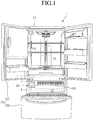
- Fig. 1 is a perspective view of a refrigerator including a quick cooling module according to an embodiment.
- a refrigerator 1 including a quick cooling module includes a main body 10 having a storage space therein, a door 20 selectively opening or closing the storage space, and a deep freezing storage compartment.
- the inner storage space of the main body 10 is partitioned by a barrier 103 to define a refrigerating compartment 12 and a freezing compartment 13.
- the refrigerating compartment 12 and the freezing compartment 13 are disposed horizontally or vertically according to an extension direction of the barrier 103.
- the refrigerating compartment 12 may be defined above/below the freezing compartment 13.
- the refrigerating compartment 12 is disposed above the freezing compartment 13.
- the refrigerating compartment 12 and the freezing compartment 13 may be disposed horizontally parallel to each other.
- the storage space including the refrigerating compartment 12 and the freezing compartment 13 may be defined as a first storage compartment
- the deep freezing storage compartment may be defined as a second storage compartment.
- the second storage compartment is a storage compartment which is maintained at a temperature less than that of the first storage compartment. For example, if the freezing compartment 13 is maintained at a temperature of about -18°C to about -20°C, the deep freezing storage compartment corresponding to the second storage compartment is maintained at a temperature of about -50°C to about -60°C.
- the deep freezing storage compartment may be disposed on an edge of a side of the freezing compartment 13.
- a drawer assembly 30 for storing foods and a quick cooling module (see Fig. 2 ) 40 for quickly cooling the inside of the drawer assembly 30 are disposed in the deep freezing storage compartment.
- the quick cooling module 40 is disposed on a rear end of the drawer assembly 30. This will be described below with reference to the accompanying drawings.
- the refrigerating compartment 12 is selectively opened or closed by a refrigerating compartment door 21. That is, the refrigerating compartment 12 may be selectively opened or closed by a single door or a pair of doors as shown in Figs. 1 .
- the refrigerating compartment door 21 may be rotatably coupled to the main body 10.
- the freezing compartment 13 is selectively opened or closed by a freezing compartment door 22.
- the freezing compartment door 22 may be withdrawably provided as shown in Fig. 1 . That is, a freezing compartment receiving part may be provided as a drawer type.
- the drawer assembly 30 may be received into the deep freezing storage compartment so that the drawer assembly 30 can withdraw in forward and backward directions.
- Fig. 2 is an exploded perspective view illustrating structures of the drawer assembly 30 and the quick cooling module 40 which are provided in the deep freezing storage compartment according to an embodiment.
- the quick cooling module 40 is disposed on the rear end of the drawer assembly 30. Also, the quick cooling module 40 may be fixed to the main body 10 or movable together with the drawer assembly 30.
- the quick cooling module 40 includes a thermal conductive unit 44 coupled to an evaporator E installed within the main body 10, a thermoelectric device 41 attached to a front surface of the thermal conductive unit 44, a heat dissipation member 42 coupled to a front surface of the thermoelectric device 41, and a heat absorption-side blow fan 43 coupled to a front surface of the heat dissipation member 42.
- the heat dissipation member 42 includes a heat sink.
- thermoelectric device 41 includes a device using a Peltier effect in which heat absorption occurs in one surface and heat emission occurs in the other surface by supplying current.
- the peltier effect represents an effect in which heat absorption occurs in one terminal and heat emission occurs in the other terminal along a current flow direction when ends of two kinds of metals are connected to each other, and then current is applied into the ends of the metals.
- a flow direction of current applied into the thermoelectric device 41 is reversed, a heat absorption surface and a heat emission surface may be also reversed.
- an amount of supplied current may be controlled to adjust an amount of absorbed and emitted heat.
- the quick cooling module 40 has a structure in which the heat absorption surface of the thermoelectric device 41 is disposed to face the drawer assembly 30 of the deep freezing storage compartment, and the heat emission surface is disposed to face the evaporator E.
- foods stored in the drawer assembly 30 may be quickly cooled at a super low temperature using the heat absorption occurring in the thermoelectric device 41 in addition to cool air supplied from the evaporator E.
- the drawer assembly 30 includes a drawer 32 and a case 31 in which the drawer 32 is withdrawably received. According to structures of products, only the drawer 32 may be received in the deep freezing storage compartment, or all the case 31 and the drawer 32 may be received in the deep freezing storage compartment.
- a rear surface of the drawer assembly 30 contacts a front surface of the quick cooling module 40, i.e., the heat absorption-side blow fan 43 to allow the cool air to forcibly flow into the drawer assembly 30 by the heat absorption-side blow fan 43.
- the thermal conductive unit 44 may be a metal plate having high conductivity such as an aluminum plate. Also, in the thermal conductive unit 44, one or a pair of plates is/are closely coupled to a refrigerant pipe of the evaporator E. In this embodiment, a pair of thermal conductive plates surround a portion of the refrigerant pipe of the evaporator E. To maximize a contact area between the refrigerant pipe and the thermal conductive unit 44, a groove in which the refrigerant pipe is seated may be defined in a surface of the thermal conductive unit 44 contacting the refrigerant pipe. Alternatively, the refrigerant pipe may pass through a side surface of the thermal conductive unit 44 which is provided in one body, and a portion of the refrigerant pipe may be buried within the thermal conductive unit 44.
- the drawer 32 may have a rectangular shape with a top surface opened.
- a sliding guide 321 extends from front to rear on both sides of the drawer 32.
- a plurality of rollers 323 are disposed on the sliding guide 321.
- a cool air flow part 322 for transferring the cool air supplied from the heat absorption-side blow fan 43 into the drawer 32 is disposed on a rear surface of the drawer 32.
- the cool air flow part 322 includes a cool air inflow hole 322a defined in an approximate center of the rear surface of the drawer 32 and a cool air discharge hole 322b defined around the cool air inflow hole 322a. When the drawer 32 is completely inserted, the cool air inflow hole 322a is disposed in a front surface of the heat absorption-side blow fan 43.
- the cool air inflow hole 322a and the cool air discharge hole 322b may be converted according to a kind of heat absorption-side blow fan 43.
- the cool air inflow hole 322a may serve as a cool air discharge hole.
- the cool air inflow hole 322a may serve as a cool air inflow hole.
- the cool air inflow hole and the cool air discharge hole may be changed in position according to their installed positions.
- the cool air inflow hole may be defined above the cool air discharge hole so that cool air inflows into an upper space of the drawer 32 to drop onto a bottom of the drawer 32 and then be discharged.
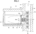
- Fig. 3 is a sectional view taken along line I-I of Fig. 1 and illustrating an installed state of a quick cooling module and a drawer assembly according to a first embodiment.
- this embodiment illustrates a structure in which only the drawer 32 is received into the deep freezing storage compartment.
- the deep freezing storage compartment may be defined at an edge of a side of the freezing compartment 13.
- the deep freezing storage compartment may be defined as an independent storage space partitioned from the freezing compartment 13 by an insulation case 104. That is, the insulation case 104 has a rectangular shape with a hollow interior. Also, the insulation case 104 may be integrated with an inner case 101 that will be described later. Also, the drawer 32 may be received into the storage space defined by the insulation case 104.
- the main body 10 includes an outer case 102 defining an outer appearance thereof and the inner case 101 provided within the outer case 102.
- a foam-filled insulation material may be between the outer case 102 and the inner case 101.
- a heat exchange chamber 105 for receiving the evaporator E may be disposed between the outer case 102 and the inner case 101.
- the inner case 101 may be a partition for partitioning the heat exchange changer 105 from the second storage compartment.
- a separate partition wall such as a plate or duct may be provided on a front surface of the inner case 101 to define the heat exchange chamber 105 between the partition wall and the inner case 101, and also, the evaporator E may be received into the heat exchange chamber 105.
- the insulation case 104 may closely abut to a front surface of the partition wall.
- a guide sleeve 101a protrudes from a wall of the freezing compartment 13 corresponding to a rear surface of the deep freezing storage compartment.
- the guide sleeve 101a may have a square pillar shape.
- a communication hole 101b is defined in the guide sleeve 101a having the square pillar shape.
- the communication hole 101b communicates with the heat exchange chamber 105.
- the wall of the freezing compartment 13 from which the guide sleeve 101a protrudes may be a rear surface of the inner case 101 or a front surface of the partition wall.
- the rear surface of the drawer 32 closely abut to a front surface of the guide sleeve 101a. That is, when the drawer 32 is completely inserted into the deep freezing storage compartment, the rear surface of the drawer 32 closely abut to the front surface of the guide sleeve 101a.
- the quick cooling module 40 is received into an inner space of the guide sleeve 101a, i.e., the communication hole 101b.
- the heat absorption-side blow fan 43 of the quick cooling module 40 closely abut to the cool air inflow hole 322a defined in the rear surface of the drawer 32.
- the heat absorption-side blow fan is provided as a blower fan, and the cool air inflow hole 322a serves as the cool air discharge hole.
- the heat emission surface of the thermoelectric device 41 is closely attached to a front surface of the thermal conductive unit 44. Thus, heat emitted from the heat emission surface may be transmitted into the refrigerant pipe of the evaporator E through the thermal conductive unit 44.
- the heat dissipation member 42 attached to the heat absorption surface of the thermoelectric device 41 is cooled at a low temperature. Air cooled by colliding and heat-exchanging with the heat dissipation member 42 is supplied into the drawer 32 by the heat absorption-side blow fan 43. Here, air existing within the drawer 32 is circulated to flow again into the heat dissipation member 42 through the cool air discharge hole 322b. Here, a portion of the cool air passing through the evaporator E and the communication hole 101b may be supplied into the drawer 32.
- foods stored in the deep freezing storage compartment may be quickly frozen at a low temperature by the cool air generated in the evaporator E in addition to the cool air generated by the thermoelectric device 41.
- the thermoelectric device 41 may be operated when the evaporator E is operated to maximize a quick freezing effect. That is, current may be applied into the thermoelectric device 41 when a refrigeration cycle is operated to circulate the refrigerant into the evaporator E. Thus, the quick freezing may be smoothly performed.
- the deep freezing storage compartment may be independently operated using the quick cooling module 40. That is, when the quick cooling within the deep freezing storage compartment is required in a state where the refrigeration cycle is stopped, current may be applied into the quick cooling module 40 to operate the thermoelectric device 41, thereby generating cool air. Also, the air generated in the thermoelectric device 41 may be supplied into the drawer 32 by operating the heat absorption-side blow fan 43.
- thermoelectric device 41 since the heat emission surface of the thermoelectric device 41 is attached to the evaporator E using the thermal conductive unit 44 as a medium, when a freezing phenomenon occurs on the evaporator E, the thermoelectric device 41 may be used as a defrosting member. That is, when current is supplied into the thermoelectric device 41 to remove ice attached on the evaporator E, heat emitted from the heat emission surface of the thermoelectric device 41 may be transmitted into the refrigerant pipe of the evaporator E through the thermal conductive unit 44. As a result, the ice attached to the evaporator E may be separated. Thus, it is unnecessary to perform a separate defrosting operation.
- thermoelectric device 41 when the flow direction of the current supplied into the thermoelectric device 41 is reversed, a front surface of the thermoelectric device 41 serves as the heat emission surface.
- the deep freezing storage compartment may serve as a quick thawing compartment.
- Fig. 4 is a sectional view taken along line I-I of Fig. 1 and illustrating an installed state of a quick cooling module and a drawer assembly according to a second embodiment.
- this embodiment is different from the first embodiment in that a drawer 32 and a case 31 are received in a deep freezing storage compartment, and a separate guide sleeve 101a is not required on a wall of a freezing compartment 13.
- other components according to this embodiment are equal to those of the first embodiment. Thus, duplicated descriptions with respect to the components equal to those of the first embodiment will be omitted.
- a drawer assembly 30 is received in a deep freezing storage compartment defined by an insulation case 104.
- a rear surface of the case 31 constituting the drawer assembly 30 closely abut to a rear surface of the freezing compartment 13.
- a communication hole 101b is defined in a rear wall of the freezing compartment 12, i.e., an inner case 101, and a quick cooling module 40 is received in the communication hole 101b.
- a cool air hole is defined in the rear wall of the case 31, particularly, a position corresponding to a cool air inflow hole 322a of the drawer 32.
- a heat absorption-side blow fan 43 of the quick cooling module 40 is disposed in the cool air hole.
- a thermoelectric device 41 of the quick cooling module 40 is fixed to a refrigerant pipe of an evaporator E using a thermal conductive unit 44 as a medium.
- Fig. 5 is a sectional view taken along line I-I of Fig. 1 and illustrating an installed state of a quick cooling module and a drawer assembly according to a third embodiment.
- this embodiment is different from the first and second embodiments in that a thermal conductive unit 44 constituting a part of the quick cooling module 40 is separated from a thermoelectric device 41.
- the quick cooling module 40 includes a thermoelectric device 41, a heat dissipation member 42 attached to a heat absorption surface of the thermoelectric device 41, a heat absorption-side blow fan 43 coupled to a front surface of the heat dissipation member 42, a thermal conductive plate 46 attached to a heat emission surface of the thermoelectric device 41, a thermal conductive unit 44 surrounding a portion of a refrigerant pipe of an evaporator E, and a heat pipe 45 connecting the thermal conductive unit 44 to the thermal conductive plate 46 to transmit heat.
- the evaporator E to which the thermal conductive unit 44 is attached is received in a heat exchange chamber 105, and the thermal conductive plate 46 is attached to a rear wall of a freezing compartment 13. Also, heat is transmitted from the thermal conductive plate 46 into the thermal conductive unit 44 by the heat pipe 45.
- the heat exchange chamber 105 and a deep freezing storage compartment are separated from each other to block movement of cool air. That is, the deep freezing storage compartment is cooled by only the quick cooling module 40.
- a portion of the quick cooling module 40 is disposed within a case 31.
- a length of the drawer 32 in front and rear directions is less than that of the case 31 in front and rear directions.
- thermoelectric device 41 heat generated in the thermoelectric device 41 is transmitted into the thermal conductive plate 46 during the quick freezing. Also, the heat transmitted into the thermal conductive plate 46 is transmitted into the thermal conductive unit 44 along the heat pipe 45.
- the thermal conductive plate 46 may be a plate formed of the same material as that of the thermal conductive unit 44.
- the thermoelectric device 41 may be attached to the heat pipe 45 through the thermal conductive plate 46. According to the above-described structure, it may prevent heat emitted in the heat emission surface of the thermoelectric device 41 from being introduced again into the deep freezing storage compartment. Thus, a temperature of the cool air supplied into the deep freezing storage compartment is lower when compared to the cases of the first or second embodiment. Actually, the cool air supplied into the deep freezing storage compartment is cooled at a temperature of about -45°C to about -50°C.
- Fig. 6 is a sectional view taken along line I-I of Fig. 1 and illustrating an installed state of a quick cooling module and a drawer assembly according to a fourth embodiment.
- this embodiment is different from the foregoing embodiments in that a length of a drawer 32 in front and rear directions is equal to that of a case 31 in front and rear directions, and a portion of a quick cooling module 40 protrudes into the drawer 32.
- portions of a heat absorption-side blow fan 43 and a heat dissipation member 42 of components constituting the quick cooling module 40 protrude into the drawer 32.
- cool air forcibly flows into the drawer 32 by the heat absorption-side blow fan 43.
- air within the drawer 32 flows toward the heat dissipation member 42, i.e., a rear side of the heat absorption-side blow fan 43 to form a cool air circulation structure in which the air is heat-exchanging with the heat dissipation member 42.
- a guide sleeve 325 for guiding circulation of the cool air protrudes from a rear surface of the drawer 32.
- the guide sleeve 325 may provide the same function as that of the guide sleeve 101a.
- a pair of guide sleeves 325 may be provided vertically or horizontally.
- a plurality of guide sleeves 325 may be provided vertically and horizontally to form one square box shape.
- the guide sleeve 325 may be disposed on a rear surface of the drawer 32 and/or a rear surface of the case 31.
- Fig. 7 is an exploded perspective view illustrating a configuration of a quick cooling module according to another embodiment.
- a quick cooling module according to this embodiment is different from the quick cooling module according to the first embodiment in a configuration of a thermal conductive unit.
- a quick cooling module 40 includes a thermoelectric device 41, a heat dissipation member 42, and a heat absorption-side blow fan 43, like the first embodiment.
- a refrigerant passage 471 through which a refrigerant flows is defined within the thermal conductive unit 47 according to this embodiment.
- a portion of a refrigerant pipe of an evaporator E is cut. An end of one side of the cut pipe is connected to an inlet side of the refrigerant passage 471, and an end of the other side of the cut pipe is connected to an outlet side of the refrigerant passage 471.
- the refrigerant flowing along the refrigerant pipe cools a thermal conductive unit 47 while flowing along the refrigerant passage 471.
- thermoelectric device 41 A heat emission surface of the thermoelectric device 41 is attached to an outer surface of the thermal conductive unit 47. Thus, heat emitted from the heat emission surface is transmitted into the refrigerant through the thermal conductive unit 47.
- Fig. 8 is a side sectional view of a drawer according to another embodiment.
- a cold plate 33 having high conductivity may be disposed on a bottom surface of the drawer 32.
- the cold plate 33 may be a metal plate formed of the same material as that of the thermal conductive units 44 and 47 or the thermal conductive plate 46 which are described in the foregoing embodiments. Since the cold plate 33 is disposed on the bottom surface of the drawer 32, lower parts of foods received in the drawer 32 may be cooled also. Thus, surfaces of the foods contacting the cool air within the drawer 32 may be cooled, and also surfaces of the foods attached to the bottom surface of the drawer 32 may be cooled. As a result, the entire surfaces of the foods may be uniformly cooled to reduce a time for cooling the foods.
- Fig. 9 is a perspective view of a drawer according to another embodiment.
- Fig. 10 is a side sectional view taken along line II-II of Fig. 9 .
- this embodiment is equal to the foregoing embodiments in a structure of the drawer in which a cool air flow part 322 having a cool air inflow hole 322a and a cool air discharge hole 322b is disposed on a rear surface of the drawer 32.
- the functions and positions of the cool air inflow hole 322a and the cool air discharge hole 322b are not limited to the proposed embodiments. That is, one of the holes constituting the cool air flow part 322 performs a function of a cool air inflow hole, and the other one performs a function of a cool air discharge hole.
- the cool air flow part 322 may be disposed vertically or horizontally on a rear surface of the drawer 32.
- This embodiment is different from the foregoing embodiments in that a plurality of cooling projections 324 protrude from a bottom surface of a drawer 32.
- cooling projections 324 each having an embossment shape, protrude from the bottom surface of the drawer 32, cool air may be smoothly transferred onto foods received in the drawer 32.
- a cool air passage is defined in a portion at which the foods contact the bottom surface of the drawer 32.
- the flow and circulation of the cool air within the drawer 32 may be promoted to increase a speed for freezing the foods, thereby reducing a freezing time. This is done because the cooling using thermal conduction as wall as the cooling using convection are performed at the same time.
- a cold plate 33 may be placed on the cooling projections 324.
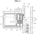
- Fig. 11 is a sectional view taken along line I-I of Fig. 1 and illustrating an installed state of a quick cooling module and a drawer assembly according to a fifth embodiment.
- a quick cooling module 40 is coupled to a case 31 of a drawer assembly 30 in one body.
- the quick cooling module 40 may be separated from a deep freezing storage compartment.
- the quick cooling module 40 includes a thermoelectric device 41, a heat dissipation member 42 mounted on a heat absorption surface of the thermoelectric device 41, a heat absorption-side blow fan 43 coupled to a front surface of the heat dissipation member 42, a heat dissipation member 48 mounted on a heat emission surface of the thermoelectric device 41, and a heat emission-side blow fan 49 mounted on a rear surface of the heat dissipation member 48.
- a partition wall 313 for partitioning a space for receiving the drawer 32 from a space for receiving the quick cooling module 40 may be disposed within the case 31. Also, a cool air hole is defined in the partition wall 313 and a rear surface of the drawer 32.
- a support wall 314 for supporting the quick cooling module 40 may be disposed within the case 31 in which the quick cooling module 40 is received.
- heat exchange spaces K1 and K2 may be defined in front and rear sides of the support wall 314, respectively.
- the thermoelectric device 41 is mounted on the support wall 314. Thus, the heat absorption surface of the thermoelectric device 41 is exposed to the front space of the support wall 314, and the heat emission surface of the thermoelectric device 41 is exposed to the rear space of the support wall 314. Thus, since heat emitted from the heat emission surface of the thermoelectric device 41 is not introduced into the drawer 32, cooling efficiency may be improved.
- a communication hole 101b communicating with a heat exchange chamber 105 is defined in a wall of a freezing compartment 13, particularly, an inner case 101 or a partition wall as described in the first embodiment.
- the heat emission-side blow fan 49 is disposed at a rear side of the communication hole 101b.
- a cool air hole 313 for introducing the cool air within the heat exchange chamber 105 into the heat exchange space K2 may be defined in a rear surface of the case 31.
- the quick cooling module 40 together with the case 31 is taken in or out of a deep freezing storage compartment, it may be necessary to selectively supply current into the blow fans 43 and 49 and the thermoelectric device 41. That is, the current supply should be interrupted when the case 31 is taken in. Also, when the case 31 is inserted into the deep freezing storage compartment, the current supply should be allowable. When a power transmission method using a wire is used, it may be difficult to treat the wire so as to supply current into a receiving device having a drawer shape. Accordingly, a unit for smoothly supplying a power is required.
- a power transmission unit 50 is mounted on a rear surface of the drawer assembly and a wall of a refrigerator main body 10.
- a wireless power transmission part 52 may be mounted on the wall of the refrigerator main body 10, and a wireless power receiving part 51 may be mounted on a rear wall of the case 31.
- the wireless power transmission part 52 and the wireless power receiving part 51 may be spaced a distance of about 15 mm or less from each other. If the spaced distance exceeds about 15 mm, power losses may be increased to cause energy losses.
- the wireless power transmission part 52 is connected to a main control part disposed on a top surface of the main body 10 to receive power.
- the wireless power receiving part 51 is electrically connected to the blow fans 43 and 49 and the thermoelectric device 41.
- the wireless power transmission unit 50 may use an electromagnetic induction method.
- An electromagnetic induction method represents a method in which magnetic fields occur around current, and thus electricity is transmitted using the magnetic fields.
- the wireless power transmission unit 50 using the electromagnetic induction method is applied to electric toothbrushes.
- the wireless power transmission unit 50 has also been applied to home appliances such as mobile phones.
- a wireless power transmission unit using resonance may be applied to the embodiments.
- the electricity when the wireless power transmission unit is applied, the electricity may be effectively supplied to a component separated from the main body 10.
- the power supply may be interrupted to reduce the power losses.
- the wire usage limitation since the wire for connecting the drawer assembly 30 to the main body 10 is removed, the wire usage limitation may be solved.
- Fig. 12 is a schematic block diagram illustrating a configuration for controlling a refrigerator including a quick cooling module according to an embodiment.
- a product in which quick cooling is required is received in a deep freezing storage compartment.
- the quick cooling mode should be performed by the user's selection to minimize power consumption.
- an input unit for selecting the quick cooling mode may be disposed on a front surface of a door 20 of a refrigerator or a drawer assembly 30.
- a display unit (not shown) may be disposed on a front surface of the door 20 of the refrigerator, or an input button may be disposed on a side of a control panel (not shown).
- the user may push the input button to operate the quick cooling module 40.
- the refrigerator includes a control unit 600, an input unit 610 including at least quick cooling mode selection button or quick cooling mode operation time input button, a driving unit 620 operated when a driving command is inputted through the input unit 610, and a memory 630 for storing information required for the at least quick cooling mode operation.
- the driving unit 620 includes a thermoelectric device 41, heat absorption-side and heat emission-side blow fans 43 and 49, and a compressor C constituting a refrigerating cycle for cooling a refrigerating compartment or a freezing compartment.
- Fig. 13 is a flowchart illustrating a process for controlling a quick cooling mood operation using the quick cooling module according to an embodiment.
- the quick cooling mode is selected through an input unit in operation S110.
- operation S120 after the quick cooling mode is selected, a quick cooling operation time is inputted.
- the quick cooling mode selection and the quick cooling operation time may be automatically set so that they are performed at the same time.
- thermoelectric device 43 In operation S130, the operation condition input for the quick cooling is completed, and an operation command is inputted through an operation button. Thus, in operation S140, the thermoelectric device 43 is operated.
- the thermoelectric device 43 being operated represents that power is applied to the thermoelectric device 43, and thus, one surface thereof is cooled and the other surface emits heat.
- thermoelectric device 43 When the thermoelectric device 43 is operated, the compressor C should be operated together.
- a control unit 600 determines whether a refrigerating cycle for cooling a refrigerating compartment or a freezing compartment is now operated in operation S150. When it is determined that the refrigerating cycle is now operated, whether a set time for the quick cooling operation has elapsed is determined in operation S160. On the other hand, if the refrigerating cycle is not operated, a control command for operating the compressor C is outputted in operation S151, and then whether the set time has elapsed is determined.
- the control unit 600 determines whether the refrigerating cycle should be continuously operated. That is, whether it is necessary to continuously operate the compressor C because the refrigerating compartment or the freezing compartment does not reach a set temperature. If it is determined that it is unnecessary to operate the refrigerating cycle any more, the operation of the compressor C is stopped and an operation of the quick cooling mode is stopped in operation S190. On the other hand, when it is determined that it is necessary to continuously operate the refrigerating cycle, the compressor C is continuously operated and the operation of the quick cooling mode is stopped in operation S190.
- the quick cooling mode may be performed by the user's selection.
- the compressor C may be operated at the same time to improve quick cooling efficiency and minimize power consumption.
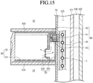
- Fig. 14 is an exploded perspective view illustrating an installed state of a quick cooling module and a drawer assembly according to a sixth embodiment.
- Fig. 15 is a sectional view taken along line I-I of Fig. 1 and illustrating the installed state of the quick cooling module and the drawer assembly according to the sixth embodiment.
- this embodiment is different from the foregoing embodiments in that a heat exchange space in which a heat dissipation member 42 is heat-exchanged with cool air within a drawer 32 is provided in a separate kit.
- a structure in which a heat exchange chamber 105 for receiving an evaporator E is disposed between an inner case 101 and a partition wall will be described. That is, an insulation material 106 is filled between the inner case 101 and an outer case 102 to prevent external air and internal air from being heat-exchanged with each other. Also, a separate space is not defined between the inner case 101 and the outer case 102. However, as described above, the partition wall is disposed at a front side of the inner case 101, and the heat exchange chamber 105 is disposed therebetween.
- a separate cool air circulation kit 33 is provided between a rear surface of the drawer 32 and a rear surface of a case 31.
- a portion of a quick cooling module 40 is disposed within the cool air circulation kit 33.
- the cool air circulation kit 33 includes a kit body 331 defining an inner space, a cool air flow duct 332provided on a side of a front surface of the kit body 331, and a module receiving groove 333 disposed in a rear surface of the kit body 331.
- cool air guide louvers are disposed at upper and lower sides of the cool air flow duct 332, respectively.
- the cool air guide louvers disposed at the upper and lower side of the cool air flow duct 332 on the basis of a cross-sectional surface which equally divides the cool air flow duct 332 may be inclined symmetrical to each other.
- cool air may be supplied into the drawer 32 through the upper louver, and the cool air within the drawer 32 may be supplied into a heat absorption-side blow fan 43 of the quick cooling module 40 through the lower louver.
- the louvers may perform a function of a rotatable damper. That is, when the quick cooling mode is not operated, the cool air flow duct 332 may be completely covered. On the other hand, when the quick cooling mode is operated, the cool air flow duct 332 may be opened.
- the quick cooling module 40 is fitted into the module receiving groove 333.
- at least the heat absorption-side blow fan 43 and the heat dissipation member 42 may be received in a heat exchange chamber kit 44.
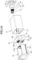
- Fig. 16 is an exploded perspective view illustrating an installed state of a quick cooling module and a drawer assembly according to a seventh embodiment.
- Fig. 17 is a sectional view taken along line I-I of Fig. 1 and illustrating an installed state of a quick cooling module and a drawer assembly according to a seventh embodiment.
- this embodiment is equal to the sixth embodiment except for a structure of a cool air circuit kit 33.
- a cool air inflow part and a cool air discharge part are separated from the cool air circulation kit 33.
- a cool air flow duct 332 of the cool air circulation kit 33 includes a cool air discharge duct 334 and a cool air inflow duct 335.
- the cool air discharge duct 334 is disposed under the cool air inflow duct 335.
- a quick cooling module 40 is disposed at a rear side of the cool air inflow duct 335.
- cool air discharged from a heat absorption-side blow fan 43 may be supplied into a drawer 32 though the cool air inflow duct 335.
- air within the drawer 32 may be guided into the cool air circulation kit 33 through the cool air discharge duct 334.
- the cool air may be smoothly circulated within a drawer assembly 30.
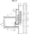
- Fig. 18 is an exploded perspective view illustrating an installed state of a quick cooling module and a drawer assembly according to an eighth embodiment.
- Fig. 19 is a sectional view taken along line I-I of Fig. 1 and illustrating the installed state of the quick cooling module and the drawer assembly according to the eighth embodiment.
- this embodiment is substantially equal to the foregoing embodiments in aspect of a drawer assembly 30 constituted by a case 31 and a drawer 32 and a quick cooling module 40 mounted on a rear surface of the drawer assembly 30.
- this embodiment is different from the foregoing embodiments in that a cool air inflow hole 73 for introducing cool air from a heat exchange chamber 105 and a cool air discharge hole 72 for discharging cool air from the drawer 32 into the heat exchange chamber 105 are provided.
- a module mounting hole 71 for mounting the quick cooling module 40 is defined in a partition wall 70.
- this embodiment is different from the foregoing embodiments in that a guide part 5 for guiding a flow of cool air and a guide duct 6 for guiding the inflow and discharge of the cool air are disposed on a front surface of the partition wall 70.
- the guide part 5 includes a guide rib 51 protruding from the front surface of the partition wall 70 to define a cool air guide passage 52 and a cover 53 seated on a front surface of the guide rib 51 to cover the cool air guide passage 52.
- the guide rib 51 may extend up to a lower end of the module mounting hole 71 along edges of the cool air inflow hole 73 and the module mounting hole 71 of the partition wall 70.
- the cool air guide passage 52 defined by the guide rib 51 may have a T-shape.
- the quick cooling module 40 passes through the partition wall 70 through the module mounting hole 71.
- a heat dissipation member 42 constituting the quick cooling module 40 is exposed to the cool air guide passage 52.
- the guide duct 60 includes a cool air inflow duct 61 and a cool air discharge duct 62.
- the cool air inflow duct 61 guides cool air, which is introduced from the heat exchange chamber 105 through the cool air inflow hole 73 of the partition wall 70 and then drops down, into the drawer 32.
- the cool air inflow duct 61 is mounted on a lower end of the cover 53.
- a heat absorption-side blow fan 43 may be mounted on the inside or at a rear side of the cool air inflow duct 61.
- a rotatably louver may be disposed on a front end of the cool air inflow duct 61 to perform a function of a damper.
- the cool air within the heat exchange chamber 105 drops down along the cool air guide passage 52 and is heat-exchanged with the heat dissipation member 42.
- the heat dissipation member 42 is heat-exchanged with a thermoelectric device 41. That is, the heat dissipation member 42 may be duplicately heat-exchanged to reduce a time which takes to quickly cool the drawer 32.
- the cool air discharge duct 62 is disposed under the cool air inflow duct 61 to communicate with the cool air discharge hole 72 of the partition wall 70.
- the cool air within the drawer 32 is recovered into the heat exchange chamber 105 through the cool air discharge duct 62.
- a rotatable louver may be disposed on the cool air discharge duct 62.
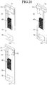
- Figs. 20 and 21 are perspective views illustrating various examples of a guide part according to an embodiment.
- a guide part of Fig. 20(a) is equal to that of Fig. 18 .
- the guide part of Fig. 20(b) is different from those of the foregoing embodiments in that a cool air inflow hole 73 defined in a partition wall 70 has a relatively narrow vertical width when compared to those of the foregoing embodiments. Since the cool air inflow hole 73 has a relatively narrow vertical width, a guide rib 51 surrounding the cool air inflow hole 73 may also have a relatively narrow vertical width.
- a quick cooling module 40 is disposed on a cool air guide passage 52 defined by a guide rib 51. Also, the quick cooling module 40 is disposed spaced downward from the cool air inflow hole 73.
- this embodiment is different from those of the foregoing embodiments in that the cool air inflow holes 73 are respectively defined in left and right sides of the partition wall 70.
- a guide rib 51 has the same shape as that of the guide rib 51 of Fig. 20(a) .
- Figs. 21(a) to 21(c) have the substantially same structure as those of Figs. 20(a) to 20(c) except that the quick cooling mode 40 is disposed directly under the cool air inflow hole 73.
- the inner space of the drawer assembly may be quickly cooled.
- the defrosting operation function for the evaporator may be performed together. Thus, it may be unnecessary to stop the operation of the refrigerating cycle or perform a reverse cycle operation so as to perform the defrosting operation for the evaporator.
- the present invention is also defined by the following items.
Landscapes
- Engineering & Computer Science (AREA)
- Physics & Mathematics (AREA)
- Mechanical Engineering (AREA)
- Thermal Sciences (AREA)
- General Engineering & Computer Science (AREA)
- Chemical & Material Sciences (AREA)
- Combustion & Propulsion (AREA)
- Devices That Are Associated With Refrigeration Equipment (AREA)
- Cold Air Circulating Systems And Constructional Details In Refrigerators (AREA)
Applications Claiming Priority (6)
| Application Number | Priority Date | Filing Date | Title |
|---|---|---|---|
| KR1020110051885A KR101768724B1 (ko) | 2011-05-31 | 2011-05-31 | 냉장고 |
| KR1020110113337A KR101848661B1 (ko) | 2011-11-02 | 2011-11-02 | 냉각장치와 보조저장실을 구비하는 냉장고 |
| KR1020110113338A KR20130048475A (ko) | 2011-11-02 | 2011-11-02 | 냉각장치와 보조저장실을 구비하는 냉장고 |
| KR1020110114572A KR101848662B1 (ko) | 2011-11-04 | 2011-11-04 | 냉각장치와 보조저장실을 구비하는 냉장고 |
| KR1020110126530A KR101861673B1 (ko) | 2011-11-30 | 2011-11-30 | 냉각장치와 보조저장실을 구비하는 냉장고 |
| EP12170001.7A EP2530408B1 (fr) | 2011-05-31 | 2012-05-30 | Réfrigérateur |
Related Parent Applications (2)
| Application Number | Title | Priority Date | Filing Date |
|---|---|---|---|
| EP12170001.7A Division EP2530408B1 (fr) | 2011-05-31 | 2012-05-30 | Réfrigérateur |
| EP12170001.7A Division-Into EP2530408B1 (fr) | 2011-05-31 | 2012-05-30 | Réfrigérateur |
Publications (1)
| Publication Number | Publication Date |
|---|---|
| EP3553419A1 true EP3553419A1 (fr) | 2019-10-16 |
Family
ID=46229217
Family Applications (2)
| Application Number | Title | Priority Date | Filing Date |
|---|---|---|---|
| EP12170001.7A Active EP2530408B1 (fr) | 2011-05-31 | 2012-05-30 | Réfrigérateur |
| EP19171517.6A Pending EP3553419A1 (fr) | 2011-05-31 | 2012-05-30 | Réfrigérateur |
Family Applications Before (1)
| Application Number | Title | Priority Date | Filing Date |
|---|---|---|---|
| EP12170001.7A Active EP2530408B1 (fr) | 2011-05-31 | 2012-05-30 | Réfrigérateur |
Country Status (3)
| Country | Link |
|---|---|
| US (4) | US9109819B2 (fr) |
| EP (2) | EP2530408B1 (fr) |
| JP (1) | JP6054639B2 (fr) |
Families Citing this family (57)
| Publication number | Priority date | Publication date | Assignee | Title |
|---|---|---|---|---|
| EP2746701A1 (fr) * | 2012-12-20 | 2014-06-25 | Whirlpool Corporation | Réfrigérateur avec un congélateur sans givre |
| ITAN20130038A1 (it) * | 2013-02-26 | 2014-08-27 | Solution Srl | Dispositivo per il funzionamento di un cassetto cantina elettrico |
| KR20140119443A (ko) * | 2013-04-01 | 2014-10-10 | 엘지전자 주식회사 | 냉장고 |
| KR102004470B1 (ko) * | 2013-04-01 | 2019-10-17 | 엘지전자 주식회사 | 냉장고 |
| CN104329866B (zh) * | 2014-03-28 | 2017-02-15 | 海尔集团公司 | 半导体制冷冰箱及其冷端换热装置 |
| CN104329868B (zh) * | 2014-03-28 | 2017-01-18 | 海尔集团公司 | 半导体制冷冰箱及其冷端换热装置 |
| US9879889B2 (en) * | 2014-07-23 | 2018-01-30 | Haier Us Appliance Solutions, Inc. | Refrigerator appliances with movable individually temperature control bins |
| CN104613804B (zh) * | 2014-12-15 | 2017-03-01 | 青岛海尔股份有限公司 | 弯折管件及具有该弯折管件的半导体制冷冰箱 |
| KR102270628B1 (ko) * | 2015-02-09 | 2021-06-30 | 엘지전자 주식회사 | 냉장고 |
| KR102273607B1 (ko) * | 2015-02-09 | 2021-07-07 | 엘지전자 주식회사 | 냉장고 |
| US10492629B1 (en) * | 2015-06-15 | 2019-12-03 | Danby Products Limited | Refrigerator |
| JP6709347B2 (ja) * | 2015-10-09 | 2020-06-17 | 青島海爾股▲フン▼有限公司 | 冷蔵庫 |
| DE102015016910A1 (de) * | 2015-12-30 | 2017-07-06 | Liebherr-Hausgeräte Ochsenhausen GmbH | Kühl- und/oder Gefriergerät |
| US20170227276A1 (en) | 2016-02-04 | 2017-08-10 | Robertshaw Controls Company | Rotary damper |
| CN105698271B (zh) * | 2016-04-01 | 2019-07-16 | 浙江嘉熙科技有限公司 | 温差电热泵型空调器 |
| US11249522B2 (en) * | 2016-06-30 | 2022-02-15 | Intel Corporation | Heat transfer apparatus for a computer environment |
| CN106196810B (zh) * | 2016-07-13 | 2018-10-30 | 合肥华凌股份有限公司 | 一种分区加热冰箱抽屉、冰箱及其控制方法 |
| KR101821289B1 (ko) * | 2016-09-02 | 2018-01-23 | 엘지전자 주식회사 | 냉장고 |
| KR101821290B1 (ko) * | 2016-09-02 | 2018-01-23 | 엘지전자 주식회사 | 냉장고 |
| CN108613455A (zh) * | 2016-12-09 | 2018-10-02 | 博西华电器(江苏)有限公司 | 抽气装置以及具有抽气装置的冰箱 |
| CN106766527A (zh) * | 2016-12-26 | 2017-05-31 | 青岛海尔股份有限公司 | 一种具有双制冷系统的冰箱 |
| EP3563106B1 (fr) * | 2016-12-28 | 2020-10-14 | Arçelik Anonim Sirketi | Dispositif de refroidissement comprenant un bouton |
| WO2018121851A1 (fr) * | 2016-12-28 | 2018-07-05 | Arcelik Anonim Sirketi | Ensemble de refroidissement rapide approprié pour être utilisé dans un réfrigérateur |
| EP3348933B1 (fr) * | 2017-01-04 | 2022-03-30 | LG Electronics Inc. | Réfrigérateur |
| KR20180080649A (ko) * | 2017-01-04 | 2018-07-12 | 엘지전자 주식회사 | 심온 냉동칸을 구비하는 냉장고 |
| KR20180087618A (ko) | 2017-01-25 | 2018-08-02 | 엘지전자 주식회사 | 저장 용기 및 이를 포함하는 냉장고 |
| AU2017403918B2 (en) * | 2017-03-15 | 2020-10-01 | Lg Electronics Inc. | Refrigerator |
| KR102309117B1 (ko) | 2017-03-21 | 2021-10-06 | 엘지전자 주식회사 | 냉장고 |
| KR102320983B1 (ko) | 2017-04-11 | 2021-11-04 | 엘지전자 주식회사 | 냉장고 |
| CN107131677A (zh) * | 2017-05-31 | 2017-09-05 | 安徽金诚天骏汽车零部件制造有限公司 | 制冷散热结构 |
| US10527339B2 (en) * | 2017-06-01 | 2020-01-07 | Haier Us Appliance Solutions, Inc. | Refrigerator appliance |
| KR102330783B1 (ko) * | 2017-06-01 | 2021-11-25 | 엘지전자 주식회사 | 냉장고 |
| BR102017018601A8 (pt) * | 2017-08-30 | 2019-11-26 | Whirlpool Sa | refrigerador |
| KR102454399B1 (ko) | 2017-09-22 | 2022-10-14 | 엘지전자 주식회사 | 냉장고 |
| US10663218B2 (en) | 2017-11-17 | 2020-05-26 | Omnicell, Inc. | Dispensing system with temperature controlled drawers |
| US11536506B2 (en) * | 2018-09-12 | 2022-12-27 | Omnicell, Inc. | Temperature controlled dispense drawer |
| BR112020008858A2 (pt) * | 2017-11-17 | 2020-10-20 | Omnicell, Inc. | gaveta de dispensa controlada por temperatura |
| KR102454181B1 (ko) * | 2017-12-19 | 2022-10-14 | 엘지전자 주식회사 | 냉장고 |
| CN110131950B (zh) * | 2018-02-08 | 2020-08-28 | 青岛海尔股份有限公司 | 一种风道组件和具有其的风冷冰箱 |
| US11472264B2 (en) * | 2018-03-07 | 2022-10-18 | Gogoro Inc. | Apparatuses for controlling environmental conditions and associated methods |
| JP2019211155A (ja) * | 2018-06-05 | 2019-12-12 | 東芝ライフスタイル株式会社 | 冷蔵庫 |
| DE102018211930A1 (de) * | 2018-07-18 | 2020-01-23 | BSH Hausgeräte GmbH | Haushaltsgerätevorrichtung |
| US20210289955A1 (en) * | 2018-07-30 | 2021-09-23 | Conopco, Inc., D/B/A Unilever | Portable freezer module |
| KR20200105611A (ko) * | 2019-02-28 | 2020-09-08 | 엘지전자 주식회사 | 냉장고 |
| KR102630192B1 (ko) * | 2019-02-28 | 2024-01-29 | 엘지전자 주식회사 | 냉장고 |
| KR20200105183A (ko) * | 2019-02-28 | 2020-09-07 | 엘지전자 주식회사 | 냉장고의 제어 방법 |
| KR102354053B1 (ko) * | 2019-03-05 | 2022-01-24 | 코웨이 주식회사 | 냉수제조장치 |
| US20220178606A1 (en) * | 2019-03-22 | 2022-06-09 | Lg Electronics Inc. | Refrigerator |
| CN111854274A (zh) * | 2019-04-26 | 2020-10-30 | 青岛海尔智能技术研发有限公司 | 制冷系统、冰箱及用于控制冰箱的方法 |
| CN111854301B (zh) * | 2019-04-26 | 2022-11-04 | 青岛海尔智能技术研发有限公司 | 散热结构、冰箱 |
| KR20210001074A (ko) * | 2019-06-26 | 2021-01-06 | 엘지전자 주식회사 | 열전 모듈 및 이를 구비한 냉장고 |
| US11375726B2 (en) * | 2020-08-06 | 2022-07-05 | John C. Hoover | Storage of post-climacteric fruit |
| CN114659336B (zh) * | 2020-12-23 | 2023-11-03 | 合肥华凌股份有限公司 | 抽屉组件及制冷设备 |
| CN112781307A (zh) * | 2020-12-24 | 2021-05-11 | 珠海格力电器股份有限公司 | 辅助换热装置及冰箱 |
| CN113503672A (zh) * | 2021-06-30 | 2021-10-15 | 澳柯玛股份有限公司 | 一种冰箱用超低温制冷系统 |
| US20230194141A1 (en) * | 2021-12-17 | 2023-06-22 | Phononic, Inc. | Countertop freezer |
| KR20230108543A (ko) * | 2022-01-11 | 2023-07-18 | 엘지전자 주식회사 | 포터블 냉장고 및 이를 포함하는 메인 냉장고 |
Citations (6)
| Publication number | Priority date | Publication date | Assignee | Title |
|---|---|---|---|---|
| JPH0282076A (ja) * | 1988-09-19 | 1990-03-22 | Toshiba Corp | 冷蔵庫 |
| JP2000329442A (ja) * | 1999-05-21 | 2000-11-30 | Sanyo Electric Co Ltd | 冷却貯蔵庫 |
| US20030115892A1 (en) * | 1999-02-26 | 2003-06-26 | Xiaoyong Fu | Thermoelectric temperature controlled refrigerator food storage compartment |
| JP2005300004A (ja) * | 2004-04-09 | 2005-10-27 | Toshiba Corp | 冷蔵庫 |
| US20090001861A1 (en) * | 2007-06-30 | 2009-01-01 | Imageworks Display And Marketing Group | Retail in-cabinet refrigeration and storage unit |
| DE102008042785A1 (de) * | 2008-10-13 | 2010-04-15 | BSH Bosch und Siemens Hausgeräte GmbH | Kältegerät |
Family Cites Families (28)
| Publication number | Priority date | Publication date | Assignee | Title |
|---|---|---|---|---|
| DE1227922B (de) * | 1960-03-16 | 1966-11-03 | Siemens Elektrogeraete Gmbh | Mit zwei Faechern verschiedener Temperatur ausgeruesteter Kuehlschrank |
| JPH0296580U (fr) * | 1989-01-13 | 1990-08-01 | ||
| JPH06147726A (ja) | 1992-10-30 | 1994-05-27 | Mitsubishi Electric Corp | 電子冷蔵庫 |
| JPH06281313A (ja) * | 1993-03-31 | 1994-10-07 | Aisin Seiki Co Ltd | 保冷庫付き化粧台 |
| JP3703889B2 (ja) | 1995-09-29 | 2005-10-05 | 昭和電工株式会社 | 冷却装置及び冷蔵庫 |
| JPH09126623A (ja) * | 1995-11-02 | 1997-05-16 | Sharp Corp | 食品貯蔵庫 |
| KR19980073158A (ko) | 1997-03-12 | 1998-11-05 | 구자홍 | 냉장고의 급속냉각보관장치 |
| KR19990016782A (ko) | 1997-08-20 | 1999-03-15 | 전주범 | 열전냉각기가 구비된 냉장장치 |
| AU3022599A (en) * | 1998-03-30 | 1999-10-18 | Junling Gao | Thermoelectric cooling device using heat pipe for conducting and radiating |
| JP2001174125A (ja) * | 1999-12-20 | 2001-06-29 | Fujitsu General Ltd | 冷蔵庫 |
| JP2002139276A (ja) * | 2000-10-31 | 2002-05-17 | Sanyo Electric Co Ltd | 冷蔵庫 |
| CN1242474C (zh) * | 2001-07-09 | 2006-02-15 | 大金工业株式会社 | 电源模块及空调机 |
| CA2384712A1 (fr) * | 2002-05-03 | 2003-11-03 | Michel St. Pierre | Echangeur thermique a passage de faisceau bride |
| KR100498386B1 (ko) * | 2002-12-06 | 2005-07-01 | 엘지전자 주식회사 | 냉장고의 냉기 토출장치 |
| KR100483919B1 (ko) | 2003-01-24 | 2005-04-18 | 삼성전자주식회사 | 열전모듈을 이용한 온도조절 챔버를 구비한 냉장고 |
| JP2004278890A (ja) * | 2003-03-14 | 2004-10-07 | Matsushita Electric Ind Co Ltd | 冷凍冷蔵庫 |
| KR20050113237A (ko) * | 2003-03-27 | 2005-12-01 | 가부시끼가이샤 도시바 | 냉장고 |
| KR100611453B1 (ko) | 2005-02-22 | 2006-08-09 | 주식회사 대우일렉트로닉스 | 저장고의 냉각 장치 조립을 위한 어셈블리 |
| US7310953B2 (en) * | 2005-11-09 | 2007-12-25 | Emerson Climate Technologies, Inc. | Refrigeration system including thermoelectric module |
| KR20070075677A (ko) * | 2006-01-14 | 2007-07-24 | 삼성전자주식회사 | 냉장고 및 이를 이용한 과냉각액 제조방법 |
| US8966926B2 (en) * | 2008-05-08 | 2015-03-03 | Whirlpool Corporation | Refrigerator with easy access drawer |
| KR100930433B1 (ko) | 2008-05-15 | 2009-12-08 | 신상용 | 급속 냉각장치 및 이를 구비한 냉장고 |
| JP2009287817A (ja) * | 2008-05-28 | 2009-12-10 | Hitachi Appliances Inc | 冷蔵庫 |
| KR101019886B1 (ko) | 2008-08-20 | 2011-03-04 | 엘지전자 주식회사 | 무동결 보관고, 과냉각 장치 및 그 제어방법 |
| KR20100025854A (ko) * | 2008-08-28 | 2010-03-10 | (주)거우엔지니어링 | 소형 냉장고 |
| KR101585941B1 (ko) * | 2008-09-22 | 2016-01-15 | 삼성전자 주식회사 | 식품열교환장치와 이를 구비한 냉장고 |
| KR101620443B1 (ko) | 2009-07-28 | 2016-05-23 | 엘지전자 주식회사 | 냉장고 |
| JP5502548B2 (ja) * | 2009-08-20 | 2014-05-28 | 株式会社東芝 | 冷蔵庫 |
-
2012
- 2012-05-30 JP JP2012123509A patent/JP6054639B2/ja active Active
- 2012-05-30 EP EP12170001.7A patent/EP2530408B1/fr active Active
- 2012-05-30 US US13/483,838 patent/US9109819B2/en active Active
- 2012-05-30 EP EP19171517.6A patent/EP3553419A1/fr active Pending
-
2015
- 2015-07-08 US US14/794,352 patent/US9464825B2/en active Active
-
2016
- 2016-09-06 US US15/257,532 patent/US9845976B2/en active Active
-
2017
- 2017-11-17 US US15/816,734 patent/US10309696B2/en active Active
Patent Citations (6)
| Publication number | Priority date | Publication date | Assignee | Title |
|---|---|---|---|---|
| JPH0282076A (ja) * | 1988-09-19 | 1990-03-22 | Toshiba Corp | 冷蔵庫 |
| US20030115892A1 (en) * | 1999-02-26 | 2003-06-26 | Xiaoyong Fu | Thermoelectric temperature controlled refrigerator food storage compartment |
| JP2000329442A (ja) * | 1999-05-21 | 2000-11-30 | Sanyo Electric Co Ltd | 冷却貯蔵庫 |
| JP2005300004A (ja) * | 2004-04-09 | 2005-10-27 | Toshiba Corp | 冷蔵庫 |
| US20090001861A1 (en) * | 2007-06-30 | 2009-01-01 | Imageworks Display And Marketing Group | Retail in-cabinet refrigeration and storage unit |
| DE102008042785A1 (de) * | 2008-10-13 | 2010-04-15 | BSH Bosch und Siemens Hausgeräte GmbH | Kältegerät |
Also Published As
| Publication number | Publication date |
|---|---|
| US20150308721A1 (en) | 2015-10-29 |
| EP2530408A2 (fr) | 2012-12-05 |
| US20120304667A1 (en) | 2012-12-06 |
| EP2530408A3 (fr) | 2017-09-20 |
| EP2530408B1 (fr) | 2019-07-03 |
| US20180087810A1 (en) | 2018-03-29 |
| US9109819B2 (en) | 2015-08-18 |
| US10309696B2 (en) | 2019-06-04 |
| US9464825B2 (en) | 2016-10-11 |
| JP6054639B2 (ja) | 2016-12-27 |
| US9845976B2 (en) | 2017-12-19 |
| JP2012251765A (ja) | 2012-12-20 |
| US20160377329A1 (en) | 2016-12-29 |
Similar Documents
| Publication | Publication Date | Title |
|---|---|---|
| US10309696B2 (en) | Refrigerator | |
| EP2627956B1 (fr) | Réfrigérateur | |
| KR101768724B1 (ko) | 냉장고 | |
| EP2787308B1 (fr) | Réfrigérateur | |
| KR102163741B1 (ko) | 냉장고 | |
| CN107110589B (zh) | 冰箱 | |
| KR101848662B1 (ko) | 냉각장치와 보조저장실을 구비하는 냉장고 | |
| KR101821290B1 (ko) | 냉장고 | |
| EP2787309A2 (fr) | Réfrigérateur | |
| KR20180087618A (ko) | 저장 용기 및 이를 포함하는 냉장고 | |
| KR20160097647A (ko) | 냉장고 | |
| WO2012105250A1 (fr) | Réfrigérateur | |
| KR20120000642A (ko) | 모듈식 냉장고 | |
| KR101821097B1 (ko) | 냉장고 | |
| KR20130060462A (ko) | 냉각장치와 보조저장실을 구비하는 냉장고 | |
| KR101946580B1 (ko) | 냉장고 | |
| CN214746668U (zh) | 冰箱 | |
| KR100380845B1 (ko) | 열전소자를 이용한 저장고 | |
| KR20060058350A (ko) | 차량용 냉온장고 | |
| US20130014524A1 (en) | Refrigerator | |
| KR101626668B1 (ko) | 냉장고 | |
| KR101927324B1 (ko) | 냉각장치와 보조저장실을 구비하는 냉장고 | |
| KR20130048475A (ko) | 냉각장치와 보조저장실을 구비하는 냉장고 | |
| KR20120084857A (ko) | 냉장고 |
Legal Events
| Date | Code | Title | Description |
|---|---|---|---|
| PUAI | Public reference made under article 153(3) epc to a published international application that has entered the european phase |
Free format text: ORIGINAL CODE: 0009012 |
|
| STAA | Information on the status of an ep patent application or granted ep patent |
Free format text: STATUS: REQUEST FOR EXAMINATION WAS MADE |
|
| 17P | Request for examination filed |
Effective date: 20190529 |
|
| AC | Divisional application: reference to earlier application |
Ref document number: 2530408 Country of ref document: EP Kind code of ref document: P |
|
| AK | Designated contracting states |
Kind code of ref document: A1 Designated state(s): AL AT BE BG CH CY CZ DE DK EE ES FI FR GB GR HR HU IE IS IT LI LT LU LV MC MK MT NL NO PL PT RO RS SE SI SK SM TR |
|
| RBV | Designated contracting states (corrected) |
Designated state(s): AL AT BE BG CH CY CZ DE DK EE ES FI FR GB GR HR HU IE IS IT LI LT LU LV MC MK MT NL NO PL PT RO RS SE SI SK SM TR |
|
| STAA | Information on the status of an ep patent application or granted ep patent |
Free format text: STATUS: EXAMINATION IS IN PROGRESS |
|
| 17Q | First examination report despatched |
Effective date: 20200827 |
|
| STAA | Information on the status of an ep patent application or granted ep patent |
Free format text: STATUS: EXAMINATION IS IN PROGRESS |