EP3553337A1 - Kupplungsanordnung für eine maschine - Google Patents
Kupplungsanordnung für eine maschine Download PDFInfo
- Publication number
- EP3553337A1 EP3553337A1 EP18382249.3A EP18382249A EP3553337A1 EP 3553337 A1 EP3553337 A1 EP 3553337A1 EP 18382249 A EP18382249 A EP 18382249A EP 3553337 A1 EP3553337 A1 EP 3553337A1
- Authority
- EP
- European Patent Office
- Prior art keywords
- friction
- clutch assembly
- clutch
- wear
- friction disc
- Prior art date
- Legal status (The legal status is an assumption and is not a legal conclusion. Google has not performed a legal analysis and makes no representation as to the accuracy of the status listed.)
- Granted
Links
Images


Classifications
-
- F—MECHANICAL ENGINEERING; LIGHTING; HEATING; WEAPONS; BLASTING
- F16—ENGINEERING ELEMENTS AND UNITS; GENERAL MEASURES FOR PRODUCING AND MAINTAINING EFFECTIVE FUNCTIONING OF MACHINES OR INSTALLATIONS; THERMAL INSULATION IN GENERAL
- F16D—COUPLINGS FOR TRANSMITTING ROTATION; CLUTCHES; BRAKES
- F16D67/00—Combinations of couplings and brakes; Combinations of clutches and brakes
- F16D67/02—Clutch-brake combinations
- F16D67/04—Clutch-brake combinations fluid actuated
-
- F—MECHANICAL ENGINEERING; LIGHTING; HEATING; WEAPONS; BLASTING
- F16—ENGINEERING ELEMENTS AND UNITS; GENERAL MEASURES FOR PRODUCING AND MAINTAINING EFFECTIVE FUNCTIONING OF MACHINES OR INSTALLATIONS; THERMAL INSULATION IN GENERAL
- F16D—COUPLINGS FOR TRANSMITTING ROTATION; CLUTCHES; BRAKES
- F16D25/00—Fluid-actuated clutches
- F16D25/06—Fluid-actuated clutches in which the fluid actuates a piston incorporated in, i.e. rotating with the clutch
- F16D25/062—Fluid-actuated clutches in which the fluid actuates a piston incorporated in, i.e. rotating with the clutch the clutch having friction surfaces
- F16D25/063—Fluid-actuated clutches in which the fluid actuates a piston incorporated in, i.e. rotating with the clutch the clutch having friction surfaces with clutch members exclusively moving axially
- F16D25/0635—Fluid-actuated clutches in which the fluid actuates a piston incorporated in, i.e. rotating with the clutch the clutch having friction surfaces with clutch members exclusively moving axially with flat friction surfaces, e.g. discs
-
- F—MECHANICAL ENGINEERING; LIGHTING; HEATING; WEAPONS; BLASTING
- F16—ENGINEERING ELEMENTS AND UNITS; GENERAL MEASURES FOR PRODUCING AND MAINTAINING EFFECTIVE FUNCTIONING OF MACHINES OR INSTALLATIONS; THERMAL INSULATION IN GENERAL
- F16D—COUPLINGS FOR TRANSMITTING ROTATION; CLUTCHES; BRAKES
- F16D66/00—Arrangements for monitoring working conditions, e.g. wear, temperature
- F16D66/02—Apparatus for indicating wear
- F16D66/021—Apparatus for indicating wear using electrical detection or indication means
- F16D66/022—Apparatus for indicating wear using electrical detection or indication means indicating that a lining is worn to minimum allowable thickness
- F16D66/023—Apparatus for indicating wear using electrical detection or indication means indicating that a lining is worn to minimum allowable thickness directly sensing the position of braking members
-
- F—MECHANICAL ENGINEERING; LIGHTING; HEATING; WEAPONS; BLASTING
- F16—ENGINEERING ELEMENTS AND UNITS; GENERAL MEASURES FOR PRODUCING AND MAINTAINING EFFECTIVE FUNCTIONING OF MACHINES OR INSTALLATIONS; THERMAL INSULATION IN GENERAL
- F16D—COUPLINGS FOR TRANSMITTING ROTATION; CLUTCHES; BRAKES
- F16D66/00—Arrangements for monitoring working conditions, e.g. wear, temperature
- F16D2066/008—Arrangements for monitoring working conditions, e.g. wear, temperature of clutches
Definitions
- the present invention relates to clutch assemblies used in machines, such as mechanical presses, for example.
- Clutch assemblies are used in various machines, such as in mechanical presses, for example.
- a clutch assembly comprises at least two main parts: a body connected to the shaft of the machine and a clutch friction disc.
- the clutch friction disc is connected to a rotating part of the machine (a flywheel, for example).
- the clutch assembly further comprises a brake friction disc, which is connected to a stationary part of the machine (to the frame, for example).
- ES2389189A1 belonging to the same applicant, discloses a clutch assembly of the latter type, comprising a piston in the body which, when actuated by pressurized air, causes the clutch friction disc to connect the body (the shaft of the machine) with the rotating part of the machine by means of friction. In this situation, the machine is engaged. When the piston is no longer actuated with pressurized air, said piston returns to its initial position with the help of springs used for such purpose. In this position, the brake friction disc connects the body (the shaft of the machine) with the stationary part of the machine by means of friction. In this situation, the machine is braked.
- the clutch assembly comprises at least:
- the clutch assembly comprises at least one detection device which is configured for detecting at least the wear of the friction sector of the clutch friction disc and is arranged in the main body.
- the detection device comprises:
- the wear sensor is configured for detecting the distance between its position and the side face of the disc that it is facing, without coming into contact with said side face, and the control device is configured for determining the wear of the friction sector arranged on said side face as a function of said detected distance.
- the main body transmits rotation of the clutch friction disc to the shaft by means of friction.
- the control device receives the measurements and is capable of interpreting these measurements to determine the wear of the friction sector corresponding.
- the distance between the wear sensor and the side face that it is facing, as well as the initial thickness of the friction sector arranged on said side face can be known beforehand, such that it can easily determine the thickness of the friction sector at the time of each reading or measurement of the distance, and it can therefore know the wear thereof.
- the wear of the friction sector is thereby determined in the proposed clutch assembly in a safe, efficient, and simple manner. Detection is furthermore performed automatically, making it easier for a user to inspect the friction sector, since said user no longer has to deal with visually inspecting them periodically.
- a clutch assembly 100 comprises at least:
- the clutch assembly 100 is a combined clutch assembly 100 (or combined brake-clutch), such as the one shown in the drawings.
- the clutch assembly 100 further comprises a brake friction disc 2 attached to a fixed part of the machine (the frame, for example), aligned with the clutch friction disc 1 such that they share the same central shaft, and comprising at least one friction sector 2.0 on each of the two side faces 2.1 and 2.2).
- the main body coupled to the shaft of the machine cooperates with the clutch friction disc 1 (with the friction sectors 1.0 of the clutch friction disc 1) by means of friction, transmitting the rotation of said clutch friction disc 1 to said shaft, and in a braking position P2 of said clutch assembly 100, the main body cooperates with the brake friction disc 2 (with the friction sectors 2.0 of the brake friction disc 2) by means of friction, braking said shaft or keeping it braked.
- clutch assembly 100 comprising a clutch friction disc 1 and a brake friction disc 2, such as the one shown in the drawings, although it is also applicable to a clutch assembly 100 that does not comprise any brake friction disc 2 (simple clutch assembly 100).
- the clutch assembly 100 shown in the drawings is actuated by means of a pneumatic actuation, but the actuation could be of another type such as hydraulic or electromagnetic actuation, for example.
- the manner of actuating the clutch assembly 100 (changing the position thereof) is not limiting in any case.
- the clutch assembly 100 comprises at least one detection device, shown in Figure 3 , which is configured for detecting at least the wear of the friction sectors 1.0 and 2.0 of the clutch friction disc 1 or brake friction disc 2, and is arranged in the main body.
- the detection device comprises:
- the wear sensor 6.0 is configured for detecting the distance between its position and the side face 1.1 and 1.2, or 2.1 and 2.2 of the disc 1 and 2 that it is facing, without coming into contact with said side face 1.1 and 1.2, or 2.1 and 2.2, and the control device 6.2 is configured for determining the wear of the friction sector 1.0 or 2.0 arranged on said side face 1.1 and 1.2, or 2.1 and 2.2 as a function of said detected distance.
- this distance is representative of the wear of the corresponding friction sector 1.0 or 2.0, the control device 6.2 being configured for determining said wear as a function of the distance.
- the control device 6.2 may furthermore be configured for indicating an alarm in the event that the wear it determines is greater than a predetermined wear threshold (when it is detected that the thickness of the corresponding friction sector 1.0 or 2.0 is less than a given thickness threshold).
- the control device 6.2 may comprise a microcontroller, a controller, a microprocessor, a FPGA or any other device at least having computing capacity.
- the clutch assembly 100 comprises at least one detection device to detect the wear of the friction sector 1.0 (or friction sectors 1.0) of the clutch friction disc 1 and at least one detection device to detect the wear of the friction sector 2.0 (or friction sectors 2.0) of the brake friction disc 2, but it preferably comprises, as is the case of the preferred embodiment, at least one respective detection device associated with each of the two side faces 1.1 and 1.2 of the clutch friction disc 1 and at least one respective detection device associated with each of the two side faces 2.1 and 2.2 of the brake friction disc 2, such that the wear of all the friction sectors 1.0 and 2.0 of both discs 1 and 2 can be determined (in the event that both discs 1 and 2 have friction sectors 1.0 and 2.0 on their two respective side faces).
- the main body of the clutch assembly 100 comprises a clutching part 3.0 arranged between both discs 1 and 2 and facing a respective first side face 1.1 and 2.1 of both discs 1 and 2, a clutch side cover 3.1 facing a second side face 1.2 of the clutch friction disc 1, and a brake side cover 3.2 facing a second side face 2.2 of the brake friction disc 2.
- the clutching part 3.0 cooperates with the first side face 1.1 of the clutch friction disc 1 (with the friction sectors 1.0 arranged on said first side face 1.1) by means of friction
- the clutch side cover 3.1 cooperates with the second side face 1.2 of the clutch friction disc 1 (with the friction sectors 1.0 arranged on said second side face 1.2) by means of friction.
- the clutching part 3.0 cooperates with the first side face 2.1 of the brake friction disc 2 (with the friction sectors 2.0 arranged on said first side face 2.1) by means of friction
- the brake side cover 3.2 cooperates with the second side face 2.2 of the brake friction disc 2 (with the friction sectors 2.0 arranged on said second side face 2.2) by means of friction.
- the wear sensor 6.0 is a contactless sensor, i.e., it does not come into contact with the face which it is facing and with respect to which the distance is to be measured. It therefore does not require being in contact with the face of the disc 1 and 2 supporting the friction sectors 1.0 or 2.0 the wear of which is to be measured, and it is not affected as the corresponding friction sectors 1.0 or 2.0 become worn (friction does not affect it). Therefore, the wear sensor 6.0 does not require being replaced when the friction sector 1.0 is replaced.
- the friction sectors 1.0 are manufactured from a non-ferromagnetic material, such that they do not interfere with the electromagnetic signal emitted and received by the wear sensor 6.0.
- the detection device further comprises a control switch 6.1 between the wear sensor 6.0 and the power unit 6.4, and an inertia sensor 6.3 which is located in the main body and preferably configured for causing the control switch 6.1 to close in the event of a change in speed of said main body, allowing the power unit 6.4 to power the wear sensor 6.0.
- a continuous reading of the distance to be measured is therefore not required, where it may only be performed when required (in this case in the event of a change in speed), which considerably reduces the energy consumption of the detection device. This furthermore allows reducing the required size of the power unit 6.4, for example.
- the inertia sensor 6.3 is communicated with the control device 6.2, such that said control device 6.2 detects when there is a change in speed of the main body, said control device 6.2 causing the control switch 6.1 to close in response to said detection.
- control device 6.2 is preferably configured for detecting the charge level of the power unit 6.4 and for closing the control switch 6.1 when it detects a change in speed of the main body, if said charge level is greater than a predetermined threshold level. It is thereby assured that the power unit 6.4 will provide enough energy to perform the corresponding reading.
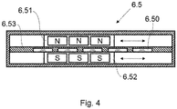
- the detection device preferably further comprises an electrical energy generator 6.5 located in the main body and configured for charging the power unit 6.4.
- the power unit 6.4 comprises a supercapacitor or a similar device, which can be recharged.
- the generator 6.5 comprises a plurality of fixed coils 6.50, a first movable mass 6.51 comprising at least a first magnet and a second movable mass 6.51 comprising at least a second magnet having a polarity opposite the first magnet, both movable masses 6.51 and 6.52 moving with respect to the coils 6.50 in the event of a change in speed of the main body, said generator 6.5 generating an electric charging current I charging the power unit 6.4 as a result of said movement.
- the coils 6.50 are arranged between the two movable masses 6.51 and 6.52, and the coils 6.50 are preferably on a printed circuit board 6.53.
- the generator 6.5 may comprise an enclosure where the elements forming it are arranged and bound.
- the detection device may further comprise a temperature sensor located in the main body, facing the same side face that the wear sensor 6.0 is facing, to enable effectively associating the temperature with the detections performed by said wear sensor 6.0.
- the reading performed by the wear sensor 6.0 can thereby be offset as required as a function of the measured temperature, if deemed appropriate.
- the evolution of the temperature together with the wear of the corresponding friction sectors 1.0 or 2.0 can be representative of how the clutch assembly 100 operates, either at too high of a rate or below what is possible, for example. If a high temperature is detected, for example, it is possible for the rate to be too high and for it to negatively affect the operation of the clutch assembly 100. So in addition to detecting the wear of the friction sectors 1.0 and/or 2.0 in a simple and effective manner, other parameters relating to the operation of the clutch assembly 100 can be determined.
- the temperature sensor comprises a protective layer manufactured in a material having a low coefficient of thermal expansion, preferably invar, so as not to be affected by external factors.
- the detection device may further comprise a communication device configured for sending the detections performed by the detection device out of the clutch assembly 100 in a wireless manner.
- the communication device can be integrated in the control device 6.2, or it can be an independent module, in which case it would be communicated with said control device 6.2 to receive the information it has to transmit.
- the communication of the communication device can be two-way (both with the control device 6.2, where appropriate, and with the outside).
- a communication device of this type is advantageous, because since the detection device is arranged in an element that rotates, it is very advantageous to be able to externalize its measurements in order to identify or treat them as required, and for this externalization to additionally be done in a wireless manner (due to the rotation, it would be very complex to be able to externalize the information with a wire).
- the detection device is a module (depicted in the form of a case in the drawings) which is arranged in the main body, where required.
- the clutch assembly 100 may comprise at least as many detection devices as there are faces with friction sectors 1.0 and/or 2.0.
- the clutch assembly 100 may comprise at least one detection device if only one of the side faces 1.1 and 1.2 of said clutch friction disc 1 comprises a friction sector 1.0, or it may comprise at least two detection devices if both side faces 1.1 and 1.2 comprise a friction sector 1.0 (one detection device for each side face 1.1 and 1.2). Similar combinations can be made for the case of a combined clutch assembly 100 (comprising a clutch friction disc 1 and a brake friction disc 2).
- a second aspect of the invention relates to a method for the detection of the wear of the friction sectors of a clutch assembly 100 like the one discussed (in any of its embodiments and/or configurations).
- measurements are taken with the wear sensor 6.0 when a change in speed in the main body is detected, as discussed, but it furthermore does so:
Landscapes
- Engineering & Computer Science (AREA)
- General Engineering & Computer Science (AREA)
- Mechanical Engineering (AREA)
- Braking Arrangements (AREA)
- Mechanical Operated Clutches (AREA)
Priority Applications (2)
| Application Number | Priority Date | Filing Date | Title |
|---|---|---|---|
| EP18382249.3A EP3553337B1 (de) | 2018-04-12 | 2018-04-12 | Kupplungsanordnung für eine maschine |
| ES18382249T ES2835036T3 (es) | 2018-04-12 | 2018-04-12 | Conjunto de embrague para una máquina |
Applications Claiming Priority (1)
| Application Number | Priority Date | Filing Date | Title |
|---|---|---|---|
| EP18382249.3A EP3553337B1 (de) | 2018-04-12 | 2018-04-12 | Kupplungsanordnung für eine maschine |
Publications (2)
| Publication Number | Publication Date |
|---|---|
| EP3553337A1 true EP3553337A1 (de) | 2019-10-16 |
| EP3553337B1 EP3553337B1 (de) | 2020-10-28 |
Family
ID=62148281
Family Applications (1)
| Application Number | Title | Priority Date | Filing Date |
|---|---|---|---|
| EP18382249.3A Active EP3553337B1 (de) | 2018-04-12 | 2018-04-12 | Kupplungsanordnung für eine maschine |
Country Status (2)
| Country | Link |
|---|---|
| EP (1) | EP3553337B1 (de) |
| ES (1) | ES2835036T3 (de) |
Cited By (1)
| Publication number | Priority date | Publication date | Assignee | Title |
|---|---|---|---|---|
| RU2810834C1 (ru) * | 2022-04-20 | 2023-12-28 | Дёнмез Дебрияж Санайи Ве Тиджарет Аноним Ширкети | Система накладки с датчиком |
Citations (7)
| Publication number | Priority date | Publication date | Assignee | Title |
|---|---|---|---|---|
| DE3244745A1 (de) * | 1982-03-12 | 1983-09-22 | VEB Kombinat Umformtechnik "Herbert Warnke" Erfurt, DDR 5010 Erfurt | Reibungskupplung und -bremse mit automatischer verschleissnachstellung |
| DE3433236A1 (de) * | 1984-09-11 | 1986-03-20 | Christo 7302 Ostfildern Vesselinoff | Kombinationsgeraet zur gleichzeitigen messung und aufzeichnung von bremspedalkraft und verzoegerungswerten |
| DE19744042A1 (de) * | 1997-10-06 | 1999-04-08 | Mannesmann Vdo Ag | Vorrichtung zum Bestimmen des Kupplungsverschleißzustandes |
| DE19754523A1 (de) * | 1997-12-09 | 1999-06-10 | Mannesmann Vdo Ag | Anordnung zur Ermittlung des Verschleißes einer Fahrzeugkupplung |
| US20080296121A1 (en) * | 2007-05-23 | 2008-12-04 | Nsk-Warner K.K. | Lubrication controlling method and lubrication controlling apparatus for starting clutch of unit type |
| US20090050418A1 (en) * | 2007-08-24 | 2009-02-26 | Victor Vargas | System and Method for Monitoring Brake Wear |
| US20120138417A1 (en) * | 2010-12-03 | 2012-06-07 | Goizper, S. Coop. | Play-free clutch and/or brake |
-
2018
- 2018-04-12 EP EP18382249.3A patent/EP3553337B1/de active Active
- 2018-04-12 ES ES18382249T patent/ES2835036T3/es active Active
Patent Citations (8)
| Publication number | Priority date | Publication date | Assignee | Title |
|---|---|---|---|---|
| DE3244745A1 (de) * | 1982-03-12 | 1983-09-22 | VEB Kombinat Umformtechnik "Herbert Warnke" Erfurt, DDR 5010 Erfurt | Reibungskupplung und -bremse mit automatischer verschleissnachstellung |
| DE3433236A1 (de) * | 1984-09-11 | 1986-03-20 | Christo 7302 Ostfildern Vesselinoff | Kombinationsgeraet zur gleichzeitigen messung und aufzeichnung von bremspedalkraft und verzoegerungswerten |
| DE19744042A1 (de) * | 1997-10-06 | 1999-04-08 | Mannesmann Vdo Ag | Vorrichtung zum Bestimmen des Kupplungsverschleißzustandes |
| DE19754523A1 (de) * | 1997-12-09 | 1999-06-10 | Mannesmann Vdo Ag | Anordnung zur Ermittlung des Verschleißes einer Fahrzeugkupplung |
| US20080296121A1 (en) * | 2007-05-23 | 2008-12-04 | Nsk-Warner K.K. | Lubrication controlling method and lubrication controlling apparatus for starting clutch of unit type |
| US20090050418A1 (en) * | 2007-08-24 | 2009-02-26 | Victor Vargas | System and Method for Monitoring Brake Wear |
| US20120138417A1 (en) * | 2010-12-03 | 2012-06-07 | Goizper, S. Coop. | Play-free clutch and/or brake |
| ES2389189A1 (es) | 2010-12-03 | 2012-10-24 | Goizper, S. Coop. | Freno-embrague sin holgura. |
Cited By (1)
| Publication number | Priority date | Publication date | Assignee | Title |
|---|---|---|---|---|
| RU2810834C1 (ru) * | 2022-04-20 | 2023-12-28 | Дёнмез Дебрияж Санайи Ве Тиджарет Аноним Ширкети | Система накладки с датчиком |
Also Published As
| Publication number | Publication date |
|---|---|
| EP3553337B1 (de) | 2020-10-28 |
| ES2835036T3 (es) | 2021-06-21 |
Similar Documents
| Publication | Publication Date | Title |
|---|---|---|
| EP1633992B1 (de) | Sensorsystem zur überwachung zumindest des verschleisses von belagmaterial von scheibenbremsen | |
| CN105308425B (zh) | 电梯制动力和距离传感器 | |
| EP2895767B1 (de) | Verfahren zur herstellung eines bremselements mit integriertem sensor, insbesondere ein bremsbelag, bremsbelag mit integriertem sensor, fahrzeugbremsanlage und zugehöriges verfahren | |
| CN103502784B (zh) | 转矩传感器设备和带有转矩传感器设备的轴 | |
| US6257374B1 (en) | Brake pad wear sensing system and method | |
| EP1762746B1 (de) | Bremsüberwachungsanordnung und Regelsystem | |
| US4658936A (en) | Brake temperature and wear indicator | |
| US8437934B2 (en) | Temperature and wear and tear sensor for brake or clutch devices | |
| US7014016B2 (en) | Brake pad clearance sensor | |
| CN109790891A (zh) | 制动衬块磨损传感器 | |
| EP3239086B1 (de) | Lösung zur überwachung einer aufzugsbremse | |
| CN107636356A (zh) | 皮带传动器和用于监测这种皮带传动器的方法 | |
| US10670098B2 (en) | Monitoring device for a disk brake of a motor vehicle | |
| US6696937B1 (en) | Wireless brake condition monitor | |
| US20100207613A1 (en) | Non-contact sensor system and method for displacement determination | |
| CN201694702U (zh) | 具有检测功能的电磁制动器 | |
| JP2020501903A (ja) | 工具パックアセンブリ | |
| EP1834109A1 (de) | Elektrisch betätigte flugzeugbremsen | |
| WO2013152807A1 (en) | Bushing wear sensing device | |
| JP2022550348A (ja) | プレスパンチに取り付けられた測定装置によって錠剤プレス機を好ましくは継続的な動作中に監視する装置及び方法 | |
| EP3553337B1 (de) | Kupplungsanordnung für eine maschine | |
| CN208295010U (zh) | 一种带有磨损检测装置的电磁制动器 | |
| CN203903709U (zh) | 一种新型的制动器状态检测装置 | |
| KR20120082411A (ko) | 전자기 스위칭 디바이스를 위한 수명 모니터링을 갖는 부가 모듈, 및 연관된 방법 | |
| JP6377755B2 (ja) | ブレーキ感知のためのシステム及び方法 |
Legal Events
| Date | Code | Title | Description |
|---|---|---|---|
| PUAI | Public reference made under article 153(3) epc to a published international application that has entered the european phase |
Free format text: ORIGINAL CODE: 0009012 |
|
| STAA | Information on the status of an ep patent application or granted ep patent |
Free format text: STATUS: THE APPLICATION HAS BEEN PUBLISHED |
|
| AK | Designated contracting states |
Kind code of ref document: A1 Designated state(s): AL AT BE BG CH CY CZ DE DK EE ES FI FR GB GR HR HU IE IS IT LI LT LU LV MC MK MT NL NO PL PT RO RS SE SI SK SM TR |
|
| AX | Request for extension of the european patent |
Extension state: BA ME |
|
| STAA | Information on the status of an ep patent application or granted ep patent |
Free format text: STATUS: REQUEST FOR EXAMINATION WAS MADE |
|
| 17P | Request for examination filed |
Effective date: 20200416 |
|
| RBV | Designated contracting states (corrected) |
Designated state(s): AL AT BE BG CH CY CZ DE DK EE ES FI FR GB GR HR HU IE IS IT LI LT LU LV MC MK MT NL NO PL PT RO RS SE SI SK SM TR |
|
| GRAP | Despatch of communication of intention to grant a patent |
Free format text: ORIGINAL CODE: EPIDOSNIGR1 |
|
| STAA | Information on the status of an ep patent application or granted ep patent |
Free format text: STATUS: GRANT OF PATENT IS INTENDED |
|
| RIC1 | Information provided on ipc code assigned before grant |
Ipc: F16D 66/02 20060101ALI20200707BHEP Ipc: F16D 25/0635 20060101AFI20200707BHEP Ipc: F16D 67/04 20060101ALI20200707BHEP |
|
| INTG | Intention to grant announced |
Effective date: 20200723 |
|
| GRAS | Grant fee paid |
Free format text: ORIGINAL CODE: EPIDOSNIGR3 |
|
| GRAA | (expected) grant |
Free format text: ORIGINAL CODE: 0009210 |
|
| STAA | Information on the status of an ep patent application or granted ep patent |
Free format text: STATUS: THE PATENT HAS BEEN GRANTED |
|
| AK | Designated contracting states |
Kind code of ref document: B1 Designated state(s): AL AT BE BG CH CY CZ DE DK EE ES FI FR GB GR HR HU IE IS IT LI LT LU LV MC MK MT NL NO PL PT RO RS SE SI SK SM TR |
|
| REG | Reference to a national code |
Ref country code: GB Ref legal event code: FG4D |
|
| REG | Reference to a national code |
Ref country code: CH Ref legal event code: EP |
|
| REG | Reference to a national code |
Ref country code: AT Ref legal event code: REF Ref document number: 1328544 Country of ref document: AT Kind code of ref document: T Effective date: 20201115 |
|
| REG | Reference to a national code |
Ref country code: DE Ref legal event code: R096 Ref document number: 602018009148 Country of ref document: DE |
|
| REG | Reference to a national code |
Ref country code: IE Ref legal event code: FG4D |
|
| REG | Reference to a national code |
Ref country code: AT Ref legal event code: MK05 Ref document number: 1328544 Country of ref document: AT Kind code of ref document: T Effective date: 20201028 |
|
| REG | Reference to a national code |
Ref country code: NL Ref legal event code: MP Effective date: 20201028 |
|
| PG25 | Lapsed in a contracting state [announced via postgrant information from national office to epo] |
Ref country code: GR Free format text: LAPSE BECAUSE OF FAILURE TO SUBMIT A TRANSLATION OF THE DESCRIPTION OR TO PAY THE FEE WITHIN THE PRESCRIBED TIME-LIMIT Effective date: 20210129 Ref country code: NO Free format text: LAPSE BECAUSE OF FAILURE TO SUBMIT A TRANSLATION OF THE DESCRIPTION OR TO PAY THE FEE WITHIN THE PRESCRIBED TIME-LIMIT Effective date: 20210128 Ref country code: FI Free format text: LAPSE BECAUSE OF FAILURE TO SUBMIT A TRANSLATION OF THE DESCRIPTION OR TO PAY THE FEE WITHIN THE PRESCRIBED TIME-LIMIT Effective date: 20201028 Ref country code: RS Free format text: LAPSE BECAUSE OF FAILURE TO SUBMIT A TRANSLATION OF THE DESCRIPTION OR TO PAY THE FEE WITHIN THE PRESCRIBED TIME-LIMIT Effective date: 20201028 Ref country code: PT Free format text: LAPSE BECAUSE OF FAILURE TO SUBMIT A TRANSLATION OF THE DESCRIPTION OR TO PAY THE FEE WITHIN THE PRESCRIBED TIME-LIMIT Effective date: 20210301 |
|
| REG | Reference to a national code |
Ref country code: LT Ref legal event code: MG4D |
|
| PG25 | Lapsed in a contracting state [announced via postgrant information from national office to epo] |
Ref country code: BG Free format text: LAPSE BECAUSE OF FAILURE TO SUBMIT A TRANSLATION OF THE DESCRIPTION OR TO PAY THE FEE WITHIN THE PRESCRIBED TIME-LIMIT Effective date: 20210128 Ref country code: SE Free format text: LAPSE BECAUSE OF FAILURE TO SUBMIT A TRANSLATION OF THE DESCRIPTION OR TO PAY THE FEE WITHIN THE PRESCRIBED TIME-LIMIT Effective date: 20201028 Ref country code: IS Free format text: LAPSE BECAUSE OF FAILURE TO SUBMIT A TRANSLATION OF THE DESCRIPTION OR TO PAY THE FEE WITHIN THE PRESCRIBED TIME-LIMIT Effective date: 20210228 Ref country code: PL Free format text: LAPSE BECAUSE OF FAILURE TO SUBMIT A TRANSLATION OF THE DESCRIPTION OR TO PAY THE FEE WITHIN THE PRESCRIBED TIME-LIMIT Effective date: 20201028 Ref country code: LV Free format text: LAPSE BECAUSE OF FAILURE TO SUBMIT A TRANSLATION OF THE DESCRIPTION OR TO PAY THE FEE WITHIN THE PRESCRIBED TIME-LIMIT Effective date: 20201028 Ref country code: AT Free format text: LAPSE BECAUSE OF FAILURE TO SUBMIT A TRANSLATION OF THE DESCRIPTION OR TO PAY THE FEE WITHIN THE PRESCRIBED TIME-LIMIT Effective date: 20201028 |
|
| REG | Reference to a national code |
Ref country code: ES Ref legal event code: FG2A Ref document number: 2835036 Country of ref document: ES Kind code of ref document: T3 Effective date: 20210621 |
|
| PG25 | Lapsed in a contracting state [announced via postgrant information from national office to epo] |
Ref country code: HR Free format text: LAPSE BECAUSE OF FAILURE TO SUBMIT A TRANSLATION OF THE DESCRIPTION OR TO PAY THE FEE WITHIN THE PRESCRIBED TIME-LIMIT Effective date: 20201028 Ref country code: NL Free format text: LAPSE BECAUSE OF FAILURE TO SUBMIT A TRANSLATION OF THE DESCRIPTION OR TO PAY THE FEE WITHIN THE PRESCRIBED TIME-LIMIT Effective date: 20201028 |
|
| REG | Reference to a national code |
Ref country code: DE Ref legal event code: R097 Ref document number: 602018009148 Country of ref document: DE |
|
| PG25 | Lapsed in a contracting state [announced via postgrant information from national office to epo] |
Ref country code: EE Free format text: LAPSE BECAUSE OF FAILURE TO SUBMIT A TRANSLATION OF THE DESCRIPTION OR TO PAY THE FEE WITHIN THE PRESCRIBED TIME-LIMIT Effective date: 20201028 Ref country code: CZ Free format text: LAPSE BECAUSE OF FAILURE TO SUBMIT A TRANSLATION OF THE DESCRIPTION OR TO PAY THE FEE WITHIN THE PRESCRIBED TIME-LIMIT Effective date: 20201028 Ref country code: SK Free format text: LAPSE BECAUSE OF FAILURE TO SUBMIT A TRANSLATION OF THE DESCRIPTION OR TO PAY THE FEE WITHIN THE PRESCRIBED TIME-LIMIT Effective date: 20201028 Ref country code: SM Free format text: LAPSE BECAUSE OF FAILURE TO SUBMIT A TRANSLATION OF THE DESCRIPTION OR TO PAY THE FEE WITHIN THE PRESCRIBED TIME-LIMIT Effective date: 20201028 Ref country code: LT Free format text: LAPSE BECAUSE OF FAILURE TO SUBMIT A TRANSLATION OF THE DESCRIPTION OR TO PAY THE FEE WITHIN THE PRESCRIBED TIME-LIMIT Effective date: 20201028 Ref country code: RO Free format text: LAPSE BECAUSE OF FAILURE TO SUBMIT A TRANSLATION OF THE DESCRIPTION OR TO PAY THE FEE WITHIN THE PRESCRIBED TIME-LIMIT Effective date: 20201028 |
|
| PG25 | Lapsed in a contracting state [announced via postgrant information from national office to epo] |
Ref country code: DK Free format text: LAPSE BECAUSE OF FAILURE TO SUBMIT A TRANSLATION OF THE DESCRIPTION OR TO PAY THE FEE WITHIN THE PRESCRIBED TIME-LIMIT Effective date: 20201028 |
|
| PLBE | No opposition filed within time limit |
Free format text: ORIGINAL CODE: 0009261 |
|
| STAA | Information on the status of an ep patent application or granted ep patent |
Free format text: STATUS: NO OPPOSITION FILED WITHIN TIME LIMIT |
|
| 26N | No opposition filed |
Effective date: 20210729 |
|
| PG25 | Lapsed in a contracting state [announced via postgrant information from national office to epo] |
Ref country code: AL Free format text: LAPSE BECAUSE OF FAILURE TO SUBMIT A TRANSLATION OF THE DESCRIPTION OR TO PAY THE FEE WITHIN THE PRESCRIBED TIME-LIMIT Effective date: 20201028 Ref country code: IT Free format text: LAPSE BECAUSE OF FAILURE TO SUBMIT A TRANSLATION OF THE DESCRIPTION OR TO PAY THE FEE WITHIN THE PRESCRIBED TIME-LIMIT Effective date: 20201028 |
|
| PG25 | Lapsed in a contracting state [announced via postgrant information from national office to epo] |
Ref country code: SI Free format text: LAPSE BECAUSE OF FAILURE TO SUBMIT A TRANSLATION OF THE DESCRIPTION OR TO PAY THE FEE WITHIN THE PRESCRIBED TIME-LIMIT Effective date: 20201028 Ref country code: MC Free format text: LAPSE BECAUSE OF FAILURE TO SUBMIT A TRANSLATION OF THE DESCRIPTION OR TO PAY THE FEE WITHIN THE PRESCRIBED TIME-LIMIT Effective date: 20201028 |
|
| PG25 | Lapsed in a contracting state [announced via postgrant information from national office to epo] |
Ref country code: LU Free format text: LAPSE BECAUSE OF NON-PAYMENT OF DUE FEES Effective date: 20210412 |
|
| REG | Reference to a national code |
Ref country code: BE Ref legal event code: MM Effective date: 20210430 |
|
| PG25 | Lapsed in a contracting state [announced via postgrant information from national office to epo] |
Ref country code: FR Free format text: LAPSE BECAUSE OF NON-PAYMENT OF DUE FEES Effective date: 20210430 Ref country code: LI Free format text: LAPSE BECAUSE OF NON-PAYMENT OF DUE FEES Effective date: 20210430 Ref country code: CH Free format text: LAPSE BECAUSE OF NON-PAYMENT OF DUE FEES Effective date: 20210430 |
|
| PG25 | Lapsed in a contracting state [announced via postgrant information from national office to epo] |
Ref country code: IE Free format text: LAPSE BECAUSE OF NON-PAYMENT OF DUE FEES Effective date: 20210412 |
|
| PG25 | Lapsed in a contracting state [announced via postgrant information from national office to epo] |
Ref country code: IS Free format text: LAPSE BECAUSE OF FAILURE TO SUBMIT A TRANSLATION OF THE DESCRIPTION OR TO PAY THE FEE WITHIN THE PRESCRIBED TIME-LIMIT Effective date: 20210228 |
|
| PG25 | Lapsed in a contracting state [announced via postgrant information from national office to epo] |
Ref country code: BE Free format text: LAPSE BECAUSE OF NON-PAYMENT OF DUE FEES Effective date: 20210430 |
|
| GBPC | Gb: european patent ceased through non-payment of renewal fee |
Effective date: 20220412 |
|
| PG25 | Lapsed in a contracting state [announced via postgrant information from national office to epo] |
Ref country code: GB Free format text: LAPSE BECAUSE OF NON-PAYMENT OF DUE FEES Effective date: 20220412 |
|
| PG25 | Lapsed in a contracting state [announced via postgrant information from national office to epo] |
Ref country code: CY Free format text: LAPSE BECAUSE OF FAILURE TO SUBMIT A TRANSLATION OF THE DESCRIPTION OR TO PAY THE FEE WITHIN THE PRESCRIBED TIME-LIMIT Effective date: 20201028 |
|
| PG25 | Lapsed in a contracting state [announced via postgrant information from national office to epo] |
Ref country code: HU Free format text: LAPSE BECAUSE OF FAILURE TO SUBMIT A TRANSLATION OF THE DESCRIPTION OR TO PAY THE FEE WITHIN THE PRESCRIBED TIME-LIMIT; INVALID AB INITIO Effective date: 20180412 |
|
| PG25 | Lapsed in a contracting state [announced via postgrant information from national office to epo] |
Ref country code: MK Free format text: LAPSE BECAUSE OF FAILURE TO SUBMIT A TRANSLATION OF THE DESCRIPTION OR TO PAY THE FEE WITHIN THE PRESCRIBED TIME-LIMIT Effective date: 20201028 |
|
| PG25 | Lapsed in a contracting state [announced via postgrant information from national office to epo] |
Ref country code: MT Free format text: LAPSE BECAUSE OF FAILURE TO SUBMIT A TRANSLATION OF THE DESCRIPTION OR TO PAY THE FEE WITHIN THE PRESCRIBED TIME-LIMIT Effective date: 20201028 |
|
| PGFP | Annual fee paid to national office [announced via postgrant information from national office to epo] |
Ref country code: DE Payment date: 20250429 Year of fee payment: 8 |
|
| PGFP | Annual fee paid to national office [announced via postgrant information from national office to epo] |
Ref country code: ES Payment date: 20250509 Year of fee payment: 8 |
|
| PG25 | Lapsed in a contracting state [announced via postgrant information from national office to epo] |
Ref country code: TR Free format text: LAPSE BECAUSE OF FAILURE TO SUBMIT A TRANSLATION OF THE DESCRIPTION OR TO PAY THE FEE WITHIN THE PRESCRIBED TIME-LIMIT Effective date: 20201028 |