EP3553220A1 - Sensor device and method for inspecting a liquid and washing machine - Google Patents
Sensor device and method for inspecting a liquid and washing machine Download PDFInfo
- Publication number
- EP3553220A1 EP3553220A1 EP18209898.8A EP18209898A EP3553220A1 EP 3553220 A1 EP3553220 A1 EP 3553220A1 EP 18209898 A EP18209898 A EP 18209898A EP 3553220 A1 EP3553220 A1 EP 3553220A1
- Authority
- EP
- European Patent Office
- Prior art keywords
- sensor
- liquid
- sensor device
- outlet
- line
- Prior art date
- Legal status (The legal status is an assumption and is not a legal conclusion. Google has not performed a legal analysis and makes no representation as to the accuracy of the status listed.)
- Granted
Links
- 239000007788 liquid Substances 0.000 title claims abstract description 131
- 238000005406 washing Methods 0.000 title claims description 52
- 238000000034 method Methods 0.000 title claims description 14
- XLYOFNOQVPJJNP-UHFFFAOYSA-N water Substances O XLYOFNOQVPJJNP-UHFFFAOYSA-N 0.000 claims abstract description 47
- 230000000694 effects Effects 0.000 claims abstract description 20
- 239000012530 fluid Substances 0.000 claims abstract description 14
- 239000000463 material Substances 0.000 claims description 31
- 239000000654 additive Substances 0.000 claims description 29
- 230000000996 additive effect Effects 0.000 claims description 17
- 239000002245 particle Substances 0.000 claims description 16
- 238000010438 heat treatment Methods 0.000 claims description 8
- 239000000126 substance Substances 0.000 claims description 7
- 238000011109 contamination Methods 0.000 claims description 4
- 238000004062 sedimentation Methods 0.000 claims description 3
- 230000000721 bacterilogical effect Effects 0.000 claims description 2
- 230000008859 change Effects 0.000 claims description 2
- 230000003287 optical effect Effects 0.000 claims description 2
- 239000004094 surface-active agent Substances 0.000 claims description 2
- 238000012544 monitoring process Methods 0.000 claims 1
- 239000011148 porous material Substances 0.000 description 19
- 239000003599 detergent Substances 0.000 description 8
- 238000013461 design Methods 0.000 description 6
- 239000013505 freshwater Substances 0.000 description 6
- 239000012535 impurity Substances 0.000 description 5
- 230000009467 reduction Effects 0.000 description 5
- 230000001914 calming effect Effects 0.000 description 4
- 230000006870 function Effects 0.000 description 4
- 230000008569 process Effects 0.000 description 4
- 238000010146 3D printing Methods 0.000 description 3
- 102000004190 Enzymes Human genes 0.000 description 2
- 108090000790 Enzymes Proteins 0.000 description 2
- 239000013543 active substance Substances 0.000 description 2
- 230000008901 benefit Effects 0.000 description 2
- 238000004891 communication Methods 0.000 description 2
- 239000002979 fabric softener Substances 0.000 description 2
- 238000012986 modification Methods 0.000 description 2
- 230000004048 modification Effects 0.000 description 2
- 230000035699 permeability Effects 0.000 description 2
- 239000004033 plastic Substances 0.000 description 2
- 238000007789 sealing Methods 0.000 description 2
- 230000004888 barrier function Effects 0.000 description 1
- 238000005452 bending Methods 0.000 description 1
- 230000009286 beneficial effect Effects 0.000 description 1
- 230000015572 biosynthetic process Effects 0.000 description 1
- 238000004140 cleaning Methods 0.000 description 1
- 230000003247 decreasing effect Effects 0.000 description 1
- 238000011161 development Methods 0.000 description 1
- 238000009826 distribution Methods 0.000 description 1
- 238000001914 filtration Methods 0.000 description 1
- 238000011010 flushing procedure Methods 0.000 description 1
- 239000006261 foam material Substances 0.000 description 1
- 239000004615 ingredient Substances 0.000 description 1
- 238000001746 injection moulding Methods 0.000 description 1
- 238000003780 insertion Methods 0.000 description 1
- 230000037431 insertion Effects 0.000 description 1
- 238000011835 investigation Methods 0.000 description 1
- 238000012423 maintenance Methods 0.000 description 1
- 238000004519 manufacturing process Methods 0.000 description 1
- 239000003550 marker Substances 0.000 description 1
- 238000005259 measurement Methods 0.000 description 1
- 230000008092 positive effect Effects 0.000 description 1
- 238000005086 pumping Methods 0.000 description 1
- 230000000630 rising effect Effects 0.000 description 1
- 229910001285 shape-memory alloy Inorganic materials 0.000 description 1
- 239000007787 solid Substances 0.000 description 1
- 239000000243 solution Substances 0.000 description 1
- 238000012360 testing method Methods 0.000 description 1
- 230000007704 transition Effects 0.000 description 1
- 238000011144 upstream manufacturing Methods 0.000 description 1
Images


Classifications
-
- G—PHYSICS
- G01—MEASURING; TESTING
- G01N—INVESTIGATING OR ANALYSING MATERIALS BY DETERMINING THEIR CHEMICAL OR PHYSICAL PROPERTIES
- G01N21/00—Investigating or analysing materials by the use of optical means, i.e. using sub-millimetre waves, infrared, visible or ultraviolet light
- G01N21/84—Systems specially adapted for particular applications
- G01N21/85—Investigating moving fluids or granular solids
-
- D—TEXTILES; PAPER
- D06—TREATMENT OF TEXTILES OR THE LIKE; LAUNDERING; FLEXIBLE MATERIALS NOT OTHERWISE PROVIDED FOR
- D06F—LAUNDERING, DRYING, IRONING, PRESSING OR FOLDING TEXTILE ARTICLES
- D06F34/00—Details of control systems for washing machines, washer-dryers or laundry dryers
- D06F34/14—Arrangements for detecting or measuring specific parameters
- D06F34/22—Condition of the washing liquid, e.g. turbidity
-
- D—TEXTILES; PAPER
- D06—TREATMENT OF TEXTILES OR THE LIKE; LAUNDERING; FLEXIBLE MATERIALS NOT OTHERWISE PROVIDED FOR
- D06F—LAUNDERING, DRYING, IRONING, PRESSING OR FOLDING TEXTILE ARTICLES
- D06F2103/00—Parameters monitored or detected for the control of domestic laundry washing machines, washer-dryers or laundry dryers
- D06F2103/16—Washing liquid temperature
-
- D—TEXTILES; PAPER
- D06—TREATMENT OF TEXTILES OR THE LIKE; LAUNDERING; FLEXIBLE MATERIALS NOT OTHERWISE PROVIDED FOR
- D06F—LAUNDERING, DRYING, IRONING, PRESSING OR FOLDING TEXTILE ARTICLES
- D06F2103/00—Parameters monitored or detected for the control of domestic laundry washing machines, washer-dryers or laundry dryers
- D06F2103/20—Washing liquid condition, e.g. turbidity
-
- G—PHYSICS
- G01—MEASURING; TESTING
- G01N—INVESTIGATING OR ANALYSING MATERIALS BY DETERMINING THEIR CHEMICAL OR PHYSICAL PROPERTIES
- G01N21/00—Investigating or analysing materials by the use of optical means, i.e. using sub-millimetre waves, infrared, visible or ultraviolet light
- G01N21/84—Systems specially adapted for particular applications
- G01N21/85—Investigating moving fluids or granular solids
- G01N2021/8557—Special shaping of flow, e.g. using a by-pass line, jet flow, curtain flow
Definitions
- the invention relates to a sensor device for the examination of a liquid, in particular in a water-conducting domestic appliance such as a washing machine, specifically for the examination of the wash liquor.
- the invention also relates to such a washing machine and a method for the examination of a liquid, preferably as previously described in a washing machine.
- the invention has for its object to provide an aforementioned sensor device for examining a liquid, a washing machine and a corresponding method with which problems of the prior art can be solved and it is particularly possible in a water-bearing household appliance such as a washing machine, a wash liquor to examine and / or clean and if necessary also to mix substances.
- the sensor device for examining a liquid has a water guide, a sensor chamber in the water guide and a sensor in or on the sensor chamber for the examination of a liquid.
- the water guide has a main channel in which liquid flows in a flow direction, an inlet line which leaves the main channel to the sensor chamber at an inlet opening, an outlet line which leads from the sensor chamber to an outlet channel. Opening at the main channel, and at least one transverse line between the inlet line and the outlet line. This transverse line is fluidly connected in parallel with the sensor chamber, wherein the outlet opening is located downstream of the inlet opening. Through this cross-line, it is possible to provide in the sensor chamber for a certain calming of the liquid, at least at a certain flow of the main channel.
- This flow of the main channel can serve to transport liquid not only to the sensor chamber but also to other areas such as a drawer of a washing machine, may be in the detergent and other additives for admixture to the washing process, if necessary, at certain times.
- the cross-line ensures a calming of the liquid in the sensor chamber, since it creates an at least partial pressure equalization between the inlet line and the outlet line. Under certain circumstances, even a calmer state can be achieved.
- the main channel can be flowed through, and yet something can be measured in the sensor chamber at a fairly or largely calmed liquid.
- a sensor in the sensor chamber can be designed in many ways, it can also be provided a plurality of sensors. It may, for example, be a turbidity sensor for contamination testing. Further possibilities for sensors are mentioned below.
- valves or flaps can be created by the invention, or the like on valves or flaps. to dispense with expensive actuators and still be able to perform several beneficial studies.
- the sensor device can be designed to be watertight except for outlet openings and inlet openings as well as possibly access openings to the outside, advantageously as a structural unit. It may have a surrounding housing with openings for the water supply or the main channel, ie for inflowing and outflow of liquid.
- at least one outlet may be provided as an opening to the bottom, advantageously to be able to remove filtered or excreted body or coarser impurities that could interfere with a process in the sensor chamber or clog fine structures.
- at least one access opening may be provided to the sensor chamber, preferably from above, either for insertion or replacement of a sensor, for example when it is broken or worn.
- so-called one-way sensors for a single cycle or washing process can be used, as they are known in particular as lab-on-the-chip and are quite inexpensive.
- the water supply with the main channel, the inlet opening and the outlet opening may be designed for a Venturi effect at the outlet opening, that to the inlet opening in the inlet line liquid entering through the Outlet opening is sucked from the outlet line into the main channel into it.
- This is advantageously done at a certain flow through the main channel, ie a certain flow rate. Due to the Venturi effect, the liquid from the main channel is sucked through the inlet opening into the inlet line, so that it also houses the sensor chamber flows through or the liquid located there exchanges. This can vary depending on the flow velocity in the main channel.
- a certain amount of calming can take place at least for the sensor chamber due to the said transverse line, since sufficient liquid can flow through this transverse line as it is sucked off by the Venturi effect in order, as it were, to largely or completely keep it away from the sensor chamber , so that the sensor chamber is only slightly or not flowed through.
- a cross-sectional constriction in the main channel can be provided in front of the outlet opening, in particular downstream of the inlet opening or behind it.
- This can serve as a Venturi nozzle for said Venturi effect, wherein preferably the outlet opening is provided within the narrowed cross-section in the main channel.
- the at least one transverse line can be closer to the inlet opening and to the outlet opening than the sensor chamber.
- a plurality of transverse conduits may be provided, and it is preferred that each of these transverse conduits be closer to the inlet port and the outlet port than the sensor chamber.
- the inlet opening, the outlet opening, a fluid resistance of the at least one transverse line and a fluid resistance of the sensor chamber may be formed such that at least a certain flow through the main channel no flow in the sensor chamber or only a low flow is present as previously stated.
- the sensor chamber is completely free of flow in this particular flow through the main channel.
- a fluid resistance of the inlet line and a fluid resistance of the outlet line can be designed such that there is no flow in the sensor chamber or only a small flow at the determined flow through the main channel. If appropriate, this can be coordinated with the aforementioned factors so that there are several possible possibilities of influencing. Although these may then have to be coordinated with great effort, consideration can be given to several conditions. There are no additional components such as valves or the like. necessary.
- the inlet pipe and / or the outlet pipe and / or the at least one transverse pipe can each have a constant cross-sectional area in their longitudinal course, in particular have a constant cross-section.
- she can be cylindrical, so to speak. So they can be easily trained.
- at least one of the lines for generating a swirling flow may be formed, for example with a swirling device explained below, preferably by a curved, meandering or curved course, or by a varying cross section which is not constant.
- at least one constriction can advantageously be present as a reduction of a cross section or as a swirling device.
- a cross-sectional area of the inlet conduit and / or the outlet conduit may be between 0.5 mm 2 and 10 mm 2 or even 20 mm 2 , preferably between 1 mm 2 and 5 mm 2 or 10 mm 2 , A cross-sectional area of the inlet conduit may be at least 10% greater than a cross-sectional area of the outlet conduit, preferably at least 50% or even at least 100%.
- the inlet conduit may be about as long as the outlet conduit, and preferably, the two conduits may be made approximately parallel. It is possible that the two lines are largely straight in one embodiment of the invention except for bends at the beginning and at the end, so that they are largely straight at least in a central region, for example over 50% to 80% of their length. However, in a particular embodiment, the inlet conduit may be at least 10% longer than the outlet conduit, preferably 20% to 50%.
- the inlet line and / or the outlet line may be formed bent, preferably with the same direction bending, and in particular extend in a plane.
- a swirling device can be provided in the water guide or in the main channel, in particular in front of the inlet opening, preferably also in a liquid line, for example in an application in an aforementioned washing machine.
- the liquid line may lead to the sensor device, so that the swirling device may be part of the sensor device or the assembly formed by it.
- the swirling device can protrude from a wall or a channel wall and thereby project into the liquid flowing in the direction of flow in such a way that it flows past it, in particular laminar flows in front of it and swirls behind or is turbulent behind it.
- the swirling device can protrude between 10% and 60% of the channel width or height in its direction of extent.
- the swirling device Due to the turbulence behind the swirling device, particles or objects contained in the liquid, in particular with a size between 0.1 mm and 5 mm, preferably 1 mm to 3 mm, can collect there. At this point, they can be removed from the further flowing liquid, what follows is explained in more detail.
- the swirling device may be formed obliquely angled or rising and project from the channel wall. In an advantageous embodiment, this can even be made variable or adjustable.
- an opening may be provided in the channel or in the corresponding liquid line, in particular on a lower region in the vertical direction, that is to say on the ground. From this floor stands or then advantageously also from the swirling device.
- the opening may or may not be closed with a movable shutter, the shutter closing this opening from above, i. it covers from above and covered, alternatively it is moved into it.
- the closure flap may be substantially rectangular in shape and connected at one side to the wall of the channel or liquid conduit which is or is around the opening.
- this is at a single upstream outer edge, in particular at a rectangular flap.
- the closure flap can be designed to be movable upwards or into the channel.
- the closure flap not only releases the opening, so as to be able to remove the collected by the vortex of the flowing liquid items. Although it can also leak some of liquid, but this does not bother. Rather, the closure flap itself, if it protrudes far enough or projects into the liquid flow, provide turbulence or at least partially or even completely form the swirling device.
- the closure flap can be fixedly arranged on the wall, in particular fixedly and non-detachably connected thereto.
- a stiffness of the closure flap is formed along the direction of flow decreasing or is less towards a free outer edge of the flap, which is opposite to the wall fixedly arranged outer edge. The flap is thus softer or more elastic towards the free outer edge or towards the free end.
- the closure flap can have or consist of two materials with different coefficients of thermal expansion.
- the materials can be connected to one another as surfaces or in planar formation.
- a first surface made of a material with a higher coefficient of thermal expansion to the outside of the channel or to the opening out.
- a second surface may be made of a material having a lower coefficient of thermal expansion to the inside of the channel or away from the opening.
- an increasing temperature may allow the first surface to expand more than the second surface, thereby deforming the baffle.
- the opening is opened or at least partially released.
- the closure flap is increasingly in the flowing liquid and thus forms the said swirling device with an effect for swirling, which is adjustable or influenced by how far the flap deforms. This in turn depends on the temperature.
- a surrounding material between the inlet line and the outlet line, which adjoins the two lines be fluid-permeable, so that liquid can pass.
- the surrounding material is porous or porous material is provided between the inlet line and outlet line, so not only adjacent to one of the two lines.
- the surrounding material is uniformly fluid-permeable or porous, preferably in the manner of a sponge.
- a pore size is more preferably less than 2 mm, preferably less than 0.5 mm or even less than 0.1 mm.
- the surrounding material an additive is introduced, which is mixed with it when flowing through the surrounding material with the liquid, that exits from the surrounding material and is mixed into the liquid.
- a dosage may possibly be very low, which can be used to advantage for metering in very small amounts of the additive.
- the additive may be, for example, an enzyme or generally a detergent-active substance which is to be added in a significantly smaller amount than a detergent or a fabric softener.
- an aforementioned access opening can be provided from outside the sensor device to the surrounding material or the porous material.
- a kind of chamber can be provided within the surrounding material be separated from the inlet line, the outlet line, the cross-line and the sensor chamber by at least the surrounding material or even sealed.
- This access opening to the chamber may be closable so that additives therein are protected and can not evaporate when in liquid form.
- introduction of the additive into the surrounding material or porous material can be facilitated.
- an entire unit of surrounding material or porous material can also be exchanged in one piece if it is provided with or contains an additive that can be released over time. After a certain time, the additive is consumed and all the porous material can be changed so that new additive is present and can be added to the liquid.
- the at least one sensor on or in the sensor chamber can be all types of sensors which can be used in water-conducting domestic appliances, in particular in washing machines or even dishwashers.
- the at least one sensor can be selected from the group consisting of pH sensor, temperature sensor, bacteriological contamination biosensor, optical sensors, turbidity sensor, spectrometer, color change sensor, surfactant sensor, conductivity sensor, hydrometer or sedimentation sensor.
- a sensor can advantageously be arranged in the upper region of the sensor chamber, in particular at a highest point of the sensor chamber.
- Other or further sensors can also be arranged in the middle of the sensor chamber, that is, if possible within the liquid, or at the bottom of the sensor chamber.
- electrical sensors in particular in the sensor chamber or also in the inlet line or the outlet line. Electrical sensors such as resistance sensors are generally fast and accurate enough, even in troubled flow conditions, for a sufficiently precise measurement, so that they do not necessarily have to be arranged in the calmed sensor chamber.
- an access opening mentioned at the beginning of the sensor device can also be provided for analysis substances, advantageously additionally or alternatively to the aforementioned access opening for additives. It can be arranged in the flow direction before, in or behind the sensor chamber. In particular, it is not provided on the possible surrounding material, so that it emits the analysis substances, if possible, only directly to the sensors or to liquid that flows directly to the sensors.
- a use of the sensor device according to the invention is carried out in a water-conducting device, in particular a household appliance, preferably in a washing machine or in a dishwasher.
- a separate sensor-liquid circuit may be provided with a sensor-liquid line to the sensor device, which may preferably also lead away from the sensor device.
- a washing machine or a dishwasher may have an additional pump, which is provided in addition to a main pump, as it is usually provided in such a device to circulate liquid during the washing process or cleaning process in the device or to circulate.
- the auxiliary pump can pump fluid to the sensor device, in particular between a drum, a heater, the sensor device and a water inlet to move or promote the drum.
- a supply line may preferably extend from the additional pump directly to the sensor device.
- the sensor device can be arranged on or in a removable device from the washing machine with detergent addition, which is preferably designed in the manner of an extendable drawer.
- the sensor device may then be connected to it and even form a structural unit, but preferably also be separated or dismounted from it.
- the sensor device can also be arranged separately from the removable device, for example above it. However, it should be accessible in any case, either simply without tools or by means of assembly work.
- the senor device may be fixedly arranged in the washing machine, where it should generally be located at a height above the drum of the washing machine. Then it should be accessible from the outside, for example, for maintenance or for refilling of additives and / or analysis substances.
- the additional pump has heating means, particularly preferably also a temperature monitor for determining the temperature of the liquid in the flow direction behind the additional pump. So it can heat up the liquid to a precise predetermined temperature.
- the sensor device can lead a liquid line in a drum or in a sump of the washing machine.
- this is done directly or skilfully over the aforementioned drawer for detergent.
- a simplified design of the lines is possible.
- the sensor device is located near the drawer, advantageously at and / or above, liquid from the sensor device can be very simple be removed and possibly also be reintroduced into the wash cycle, for example, after the aforementioned additives have been added.
- the sensor-liquid circuit may begin at a sump or at a drum of the washing machine or there may be provided an inlet into the sensor-liquid circuit, preferably towards the additional pump.
- the distance of the additional pump to the sump can be low, advantageously with a maximum of 20 cm line between them, so that the additional pump can be arranged relatively far below.
- fresh water can be supplied from a fresh water supply into the sensor device. This may be possible in addition to or as an alternative to the supply of wash water by means of the aforementioned additional pump. This supply can preferably be shut off by means of a valve. This fresh water supply to the sensor device can be done with its own fresh water line similar to an aforementioned drawer.
- a liquid can be examined with a previously described sensor device and / or with a previously described washing machine.
- a flow through the sensor device in particular the main channel of the sensor device, can be adjusted with liquid such that while liquid is contained in the sensor chamber, but this is not or only slightly moved. At least some liquid should remain there, which is then examined.
- the sensor chamber within the sensor device, in particular with regard to its altitude compared to the inlet line and outlet line, can be set that it is always at least partially filled with liquid, even if the liquid does not flow or flows through the sensor device.
- the sensor chamber may be arranged so that it is self-draining when the liquid is not flowing or flowing through the sensor device. Then contamination by stagnant water in the sensor chamber and especially at the sensors can be avoided.
- the flow through the sensor device and in particular the main channel with liquid is adjusted such that a venturi effect results at the outlet opening such that liquid entering the inlet opening into the inlet line is conveyed through the outlet opening. Opening is sucked from the outlet line into the main channel.
- the closure flap itself may also cause the said swirling of the flowing liquid and thus also cause the collecting of the impurities or particles behind it, which allows the subsequent removal through the opening as an outlet.
- the flow through the sensor device or the main channel can be adjusted with liquid such that liquid can flow through the fluid-permeable or porous surrounding material described above. Under certain circumstances, this may depend on the flow or, in particular, on the pressure of the flowing liquid.
- an additive in the fluid-permeable surrounding material can be dissolved out and admixed with the liquid, as has been described above.
- marker substances can be added as additives via the fluid-permeable surrounding material into the water guide and into the liquid therein.
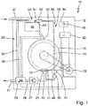
- the Fig. 1 shows a schematic representation of a washing machine 11 according to the invention with a housing 12 in which a drum 14 is arranged in a drum housing 16 in the usual manner.
- a drive motor 18 is provided for the drum 14, which is driven in the usual way and is supplied with power accordingly.
- the washing machine 11 has a circulation guide 23 for the water during operation or a washing process. This leads from the sump 24 a sump line 25 down and to the left to a pump 27. This is advantageous a circulating pump for the washing machine 11 and, for example, according to the DE 10 2013 211 180 A1 be educated. It may have a separate or integrated heater to heat the pumped water instead of the heater 21 to a certain temperature.
- a pump line 28 is provided towards a valve means 29 which can distribute the liquid flow, so to speak. From the valve device 29 goes to the left a sewer line 31 down to an outflow from the washing machine 11 and into the sewer. Furthermore, the valve device 29 is followed by a circulation line 33 from above, which again leads directly into the drum housing 16 from above. Thus, water can circulate directly during the washing process, through the drum 14 therethrough.
- a drawer line 34 leads upwards, which leads into a drawer 39 arranged at the top in the washing machine 11.
- the drawer 39 may be formed according to the prior art and several compartments for filling detergents and / or additives such as fabric softener odgl. exhibit. You can also according to the PCT / EP 2017/077358 with filing date of 25 October 2017 be formed by the same applicant and contain sensors and / or filters. A filtering in the drawer 39 can according to the PCT / EP 2017/077357 with filing date of 25 October 2017 be provided. In this drawer 39 and to her out leads from the outside still a fresh water line 37. The drawer 39 thus forms part of a distribution system 38. Down of the drawer 39 is a drawer line 40 into the drum housing 16 so as to circulate with Rinse out water or fresh water and take entrained additives or detergent from the drawer 39 into the drum 14 and thus in the washing process.
- a pump 50 From the sump line 25 goes to the right from a branch line 48, which leads to a pump 50.
- This pump 50 can in principle be of any desired design, in particular also as an impeller pump. Behind her heating means 51 may be provided, but, as described in relation to the pump 27, may also be integrated into the additional pump 50.
- Via a sensor line 53 water from the sump 24 can be pumped up separately from the circulation guide 23.
- the sensor line 53 opens into a sensor device 58 according to the invention, which will be explained in more detail below. From the sensor device 58 goes to the left from a sensor introduction, which leads into the drawer 39. At the bottom of the sensor device 58, an outlet 89 descends, the outlet 89 advantageously being arranged from the water guide at the beginning of the sensor device 58 and leaving it. Details of the sensor device 58 will be explained in connection with the other figures.
- the washing machine 11 has a washing machine control 42, advantageously provided with a controller or microprocessor.
- the washing machine controller 42 is connected to the drive motor 18, the pump 27, the heater 21, the temperature sensor 22, the valve device 29 and the auxiliary pump 50 and the heating means 51.
- the washing machine controller 42 is of course also connected to the sensor device 58 in a manner not shown, either by a cable or wirelessly.
- a power supply in the form of a battery as well as a wireless communication device, in particular a radio device should be provided to the washing machine control 42.
- the washing machine controller 42 is provided with an operating device 44, which has, inter alia, an on-switch and other controls.
- the washing machine controller 42 is also designed to control and / or evaluate sensors in the sensor device 58 and to control the use of the sensor device as a whole.
- a sensor device according to the invention 58 shown from above in magnification and in detail, as it is connected to the sensor line 53 coming from the left. To the right it is connected to the sensor introduction 54.
- the sensor device 58 has a housing 60, advantageously made of plastic.
- the housing 60 and possibly the sensor device 58 except for sensors may in particular be manufactured in an additive and one-piece manner, either by injection molding or advantageously by 3D printing.
- a water guide 62 is generally formed with a plurality of channels and lines.
- a main channel 64 is provided. This one points in the Fig. 2 an inlet port 66, which may be considered as a kind of branch, to which an inlet conduit 67 adjoins.
- This inlet line 67 is part of a U-shape, so to speak, forming its left vertical leg. Below it makes a turn to the right and leads into an extended sensor chamber 69, so that approximately the base of the U-shape is formed here.
- various sensors can be arranged in general, here it is a turbidity sensor 71 and a pH sensor 73.
- transverse lines 78a and 78b between the inlet line 67 and the outlet line 75 are provided in a middle area which is flushed around so to speak; it could also be only one and above all more. Their cross section is here significantly less than that of the two lines mentioned, this is also on the Fig. 3 referenced with better representation of the same.
- the transverse lines 78a and 78b cause a kind of liquid bypass to be created parallel to the sensor chamber 69 and thus the liquid sucked by said venturi effect flows mainly through these transverse lines and not so much through the sensor chamber 69.
- the particularly advantageous effect can be achieved that at least at a certain flow through the main channel 64, although liquid is sucked at the outlet opening 76, but this flows, so to speak mainly through the transverse lines 78a and 78b.
- the flow can then be reduced, in particular without turbulence or turbulence. Possibly, the flow chamber 69 may even be largely or completely flow-free.
- turbidity sensor 71 can then work very well, for example because some ingredients at least partially in the Can settle liquid.
- sedimentation sensors could also be provided.
- the two transverse lines 78a and 78b do not differ in terms of their cross-sectional area, but in terms of their course.
- the upper cross-line 78a is straight, the lower cross-line 78b runs meandering as mentioned at the outset as an example.
- the flow velocity is reduced in the lower transverse line 78b, which can likewise be advantageously utilized, for example for the important influencing or reduction of the flow through the sensor chamber 69.
- a major part of the housing 60 of the sensor device 58 can be made of plastic and can be impermeable to water, in particular also stable and opaque.
- porous material 80th be provided here, represented by the cross-hatching.
- This porous material 80 may be formed, for example, in the manner of a sponge or foam material. Such materials can also be produced by the aforementioned 3D printing.
- the porous material 80 is to some extent permeable to water, but only somewhat so that water can pass through, but no real flow results.
- This water permeability of the porous material 80 can also serve to calm the liquid in the sensor chamber 69 or make it largely flow-free in the aforementioned specific flow through the main channel.
- certain other additives which thus very gradually and especially to a small extent, depending on the nature or duration of the flow through the sensor device 58, solved and the liquid flowing therethrough can be mixed.
- These may be, for example, markers or wash-active substances with enzymes or other substances which are known in the field of washing, in particular with modern methods or modern detergents.
- a chamber 82 is provided in the porous material 80 from above, advantageously several such chambers 82.
- the lateral sectional view corresponding to the section AA according to Fig. 3 shows that this chamber 82 is provided at the top with an access opening 81 which can be sealed.
- certain additives can be introduced into the chamber 82 from above, in any desired form, ie liquid, solid or pulverulent. Since the chamber 82 comes into direct contact with the liquid or the liquid also comes through the porous material 80 and also to the chamber 82, something permanently from the introduced there additive can be washed or taken away.
- This type of metering may be influenced by configuring the porosity or permeability of the porous material 80, the conduit cross-sections or open areas of the porous material 80, and the manner in which the additive is introduced into the chamber 82.
- the entire unit of the porous material 80 may be a type of block or the like. or be replaced in one piece, if it is consistently or completely mixed with an additive, so that the additive can deliver over time. After a certain time, the additive is consumed, and the entire unit of the porous material 80 can be replaced, so that new additive is present again and can be mixed into the liquid.
- a variant of a sensor device 158 is shown in fragmentary form with a housing 160 and a water guide 162 therein.
- the special feature here is that in the sensor housing 160, the inlet opening 166, as it were inclined to the flow direction obliquely from the main channel 164. Thus, so to speak, a little more liquid can flow into the inlet line 167.
- the transition of the outlet opening 176 is in the main channel 164 just before a sensor inlet 154 mirrored to the right obliquely formed, whereby the venturi effect described can be influenced and above all reinforced.
- Behind the inlet opening 166 and in front of the outlet opening 176, inlet conduit 167 and outlet conduit 175 are provided, which in turn extend as in FIG Fig. 2 shown or run parallel.
- a greater flow through the sensor device 158 is likely to be achieved, in particular with greater inflow of liquid into the water guide 162 or toward the transverse lines and a sensor chamber.
- FIG. 5 is yet another modification of a sensor device 258 with a housing 260 in plan view shown together with water supply 262.
- a main channel 264 goes down an inlet opening 266 from an inlet line 267.
- this inlet pipe 267 is curved and extends behind the curvature region in a straight line and in particular parallel to the main channel 264. It leads to a sensor chamber 269 with sensors 271 and 273 therein.
- An outlet conduit 275 then joins thereto, first parallel thereto, and then with a short bend towards an outlet port 276 which in turn leads into the main conduit 264.
- inlet line 267 and outlet line 275 again run approximately parallel to each other, but first curved.
- the region of the water guide 262 in which four transverse conduits 278a-278d pass between the inlet conduit 267 and the outlet conduit 275 is substantially parallel to the direction of the main conduit 264 and not at right angles thereto as in FIG Fig. 2 .
- the throughflow of the water guide 262 or the sensor device 258 can also be influenced by the thus achievable different lengths of inlet line 267 and outlet line 275, so that the sensor chamber 269 can be kept free of flow as far as possible with at least one specific flow.
- the inlet conduit 267 is longer than the outlet conduit 275, about 10% to 20%.
- the aspect that the sensor chamber of the sensor device should be kept as free of flow at least one flow, therefore, is that then even with flowing through the liquid from the additional pump 50 according to Fig. 1 pumped, can be measured with the sensors.
- This additional pump 50 can be used in addition to bring liquid, in particular from the sump 24, in the drawer 39 for targeted rinsing of detergents and / or additives into the drum 14 via the drawer conduit 40.
- This is before especially advantageous if, for example, the drawer line 34 is not provided or the pump 27 is not to be operated, but just the auxiliary pump 50.
- a cross-sectional area of inlet conduit 67 and / or outlet conduit 75 may be, for example, between 1 mm 2 and 10 mm 2 , depending on how large the sensor device 58 may or should, in particular depending on how many sensors in the sensor chamber 69 should be arranged. Possibly, a cross-sectional area of the inlet conduit 67 may also be greater than that of the outlet conduit 75 or at least related to the inlet port 66 and the outlet port 76, also providing a flow-calmed sensor chamber in communication with the transverse conduits 78a and 78b 69 can be created. The difference in cross-sectional area can be about 10% to 50% here.
- a turbidity sensor 71 is formed in two parts and can be provided both on a ceiling and on a bottom of the sensor chamber 69.
- this turbidity sensor 71 and other sensors reference is made to the respective prior art. Also, an electrical connection of these sensors 71 and 73 to the washing machine control 42 is not shown, but easy to implement.
- a reduction of the flow in the sensor chamber 69 due to the design of the water guide 62, in particular with the transverse lines 78a and 78b, may be such that the flow through the sensor chamber 69 is reduced by at least 10%, preferably by at least 50% or even in order at least 80%.
- the flow rate of liquid through the sensor chamber 69 can thus be reduced according to these values without mechanical elements such as valves, valves or the like. needed.
- a sensor device 58 according to the invention can be as simple as possible and at the same time function as reliably as possible.
- pins or pegs which project from a lateral chamber wall into the sensor chamber 69.
- they can only protrude from one chamber wall into the sensor chamber 69, for example according to one of the two parts of the turbidity sensor 71 only from above or only from below. They can reach at least to the middle, advantageously even further.
- they may extend from two opposing chamber walls as well as the two parts of the turbidity sensor 71.
- a length of such pins or pegs is advantageously greater than their diameter, more preferably twice as large to 10 times as large.
- a swirling device may be provided, as in Fig. 6 is shown schematically in plan view with magnification in Fig. 7 and side view in Fig. 8 ,
- a swirling device 85 is arranged in the sensor line 53, advantageously just before the sensor device 58 or even integrated therein, in particular in its structural unit, which is formed mainly by the housing 60 and the water guide 62 therein. It has a projection 86 which, according to the lateral view of Fig. 8 can be designed as a kind of gate or towering wall.
- the projection 86 may be formed closed, possibly with openings, depending on the type or strength of the desired turbulence. In the flow direction downstream or shortly behind the projection 86, a rectangular opening 88 is provided downwardly, which opens into an outlet 89. This one is in the Fig. 1 shown above the drawer 39, so that the outlet 89 can open into the drawer 39. Alternatively, it can open in a manner not shown here in a sewer line 31, so that according to Fig. 8 emerging particles 90 as objects or impurities equal to be led out of the washing machine 11 completely.
- the outlet port 88 is closed with a shutter 91 which is connected to the right by means of a bearing 92 with a bottom of the main channel 64 and the sensor line 53 or attached thereto. This is also out Fig. 8 clearly visible.
- the in Fig. 7 and 8th produced turbulence, which cause the particles 90 located in the liquid to accumulate behind the projection 86, since they are ejected from the fluid swirling, so to speak.
- This effect is known as the snow-fence effect.
- a barrier or protrusion in a flowing liquid, possibly also in flowing air causes turbulence downstream thereof.
- objects or particles contained in the liquid or in the fluid are excreted, as it were.
- the outlet opening 88 is used for this purpose. If no particles 90 are to be removed from the liquid, the closure flap 91 remains at the bottom and closes the outlet opening 88. On the other hand, if it is moved upward into the position shown in dashed lines, then the outlet opening is 88 opened and the particles 90 together with leaking liquid can be flushed out through the outlet 89. Of course, some of the liquid is lost or is dissipated, but at the same time the particles 90 are also removed. About the opening angle of the flap 91, this can also be influenced somewhat.
- the closure flap 91 can, of course, be driven as desired for opening, for example with an external actuator such as an electric motor or an electromagnet, alternatively a shape memory alloy, a bimetal or the like.
- an external actuator such as an electric motor or an electromagnet, alternatively a shape memory alloy, a bimetal or the like.
- it consists of two materials with different thermal expansion coefficients.
- An upper material layer 94 of the two-ply closure flap 91 has a lower coefficient of thermal expansion, and a lower material layer 95 has a higher coefficient of thermal expansion.
- the two layers of material 94 and 95 are firmly and permanently connected to each other and secured by means of the bearing 92 at the bottom of the main channel 64.
- the outlet opening 88 is thus largely or advantageously completely closed.
- These elastic sealing means such as a sealing rubber or the like. be provided on the closure flap and / or outlet opening. If the temperature in the liquid flowing through it is increased, for example, by operation of the heating means 51 behind the additional pump 50, so the shutter 91 is heated. Then, similar to a known bimetal effect, the lower material layer 95 expands more than the upper material layer 94, resulting in a deflection of the flap 91 upwards. By way of example, the bend can be so far that the free end of the closure flap 91 reaches half the height or even the entire height of the projection 86.
- An angle in a linear view between the bearing 92 on the right and the free end can then be between 10 ° and 25 °, so that the outlet opening 88 is substantially opened wide for rinsing the particles 90. If a greater deflection of the flap 91 is possible without being mechanically damaged with continued use, it can also be made shorter, so that the outlet opening 88 is shorter, so that slightly less liquid from the main channel 64 can escape.
- closure flap 91 operated in accordance with Fig. 9 is that can be dispensed with external and / or mechanical actuators, which causes a simplification and significantly reduces the design effort. Furthermore, an influence can also be achieved only with the said heating means 51, which may not only have to be arranged close to the additional pump 50, possibly also much closer to the closing flap.
- FIG Fig. 10 Yet another alternative embodiment of a simplified swirler 385 in a main channel 364 is shown in FIG Fig. 10 shown.
- a swirling device 385 is provided which, so to speak, manages without the projection and has only one closing flap 391.
- This shutter 391 is attached directly to a bottom of the main channel 364, particularly formed directly on it in 3D printing during manufacture.
- the closure flap 391 is advantageously similar Fig. 9 made of two layers of material with different coefficients of thermal expansion in order to operate them easily and without separate external actuators can.
- the closure flap 391 can be moved upwards, advantageously as described above by heating the liquid. Then the shutter 391 projects steeply upwards, here with an angle between 50 ° and 80 ° at the free end. Thus, it provides a clear obstacle corresponding to the projection 86 in FIG Fig. 8 for the liquid flowing around, so that the turbulences described above result downstream of the closure flap 391, as shown by the arrows. As a result, particles 390 are ejected or eliminated. There As the outlet opening 388 opens upwards as the closure flap 391 flexes, the particles 390 may be removed from the main channel 364 along with some liquid. This is advantageously done via an outlet as before for the embodiment of Fig. 6 to 8 explained.
- Coarser particles or articles may be filtered out of the liquid in the manner described above without the need for other filters which may be clogged or added and then manually cleaned or changed. By keeping these particles away from the sensor chamber, the function of sensors arranged therein can be improved. In addition, it can be achieved that the relatively thin transverse lines and possibly also the porous material are added or clogged.
- a reduction of the flow in the sensor chamber 69 due to the design of the water guide 62, in particular with the transverse lines 78a and 78b, may be such that the flow through the sensor chamber 69 is reduced by at least 10%, preferably by at least 50% or even in order at least 80%.
- the flow rate of liquid through the sensor chamber 69 can thus be reduced according to these values without mechanical elements such as valves, valves or the like. needed.
- a sensor device 58 according to the invention can be as simple as possible and at the same time function as reliably as possible.
Abstract
Eine Sensorvorrichtung (58) zur Untersuchung einer Flüssigkeit weist eine Wasserführung (62), eine Sensorkammer (69) darin und einen Sensor (71, 73) in oder an der Sensorkammer (69) zur Untersuchung einer Flüssigkeit auf. Die Wasserführung (62) weist einen Haupt-Kanal (64), in dem Flüssigkeit in einer Fließrichtung entlang strömt, eine Einlass-Leitung (67), die an einer Einlass-Öffnung (66) von dem Haupt-Kanal (64) abgeht zu der Sensorkammer (69) und eine Auslass-Leitung (75) auf, die von der Sensorkammer (69) abgeht zu einer Auslass-Öffnung (76) an dem Haupt-Kanal (64), wobei die Auslass-Öffnung (76) flussabwärts von der Einlass-Öffnung (66) liegt. Es ist mindestens eine Quer-Leitung (78) zwischen der Einlass-Leitung (67) und der Auslass-Leitung (75) vorgesehen, wobei die Quer-Leitung (78) fluidtechnisch parallel geschaltet ist zu der Sensorkammer (69). Eine Strömung durch die Quer-Leitung (78) kann bewirken, dass bei kontinuierlicher Strömung durch den Haupt-Kanal (64) in der Sensorkammer (69) nur eine verringerte oder gar keine Strömung herrscht.A sensor device (58) for examining a liquid has a water guide (62), a sensor chamber (69) therein and a sensor (71, 73) in or on the sensor chamber (69) for examining a liquid. The water guide (62) has a main channel (64) in which liquid flows along in a direction of flow, an inlet line (67) which leads from the main channel (64) at an inlet opening (66) the sensor chamber (69) and an outlet line (75), which leads from the sensor chamber (69) to an outlet opening (76) on the main channel (64), the outlet opening (76) downstream of the inlet opening (66). At least one cross line (78) is provided between the inlet line (67) and the outlet line (75), the cross line (78) being connected in fluid technology in parallel to the sensor chamber (69). A flow through the transverse line (78) can have the effect that, with a continuous flow through the main channel (64) in the sensor chamber (69), there is little or no flow.
Description
Die Erfindung betrifft eine Sensorvorrichtung zur Untersuchung einer Flüssigkeit, insbesondere in einem wasserführenden Haushaltsgerät wie einer Waschmaschine, und zwar zur Untersuchung der Waschlauge. Die Erfindung betrifft außerdem eine solche Waschmaschine und ein Verfahren zur Untersuchung einer Flüssigkeit, vorzugsweise wie zuvor beschrieben in einer Waschmaschine.The invention relates to a sensor device for the examination of a liquid, in particular in a water-conducting domestic appliance such as a washing machine, specifically for the examination of the wash liquor. The invention also relates to such a washing machine and a method for the examination of a liquid, preferably as previously described in a washing machine.
Der Erfindung liegt die Aufgabe zugrunde, eine eingangs genannte Sensorvorrichtung zur Untersuchung einer Flüssigkeit, eine Waschmaschine und ein entsprechendes Verfahren zu schaffen, mit denen Probleme des Standes der Technik gelöst werden können und es insbesondere möglich ist, in einem wasserführenden Haushaltsgerät wie einer Waschmaschine eine Waschlauge zu untersuchen und/oder zu reinigen und ggf. auch Stoffe beizumischen.The invention has for its object to provide an aforementioned sensor device for examining a liquid, a washing machine and a corresponding method with which problems of the prior art can be solved and it is particularly possible in a water-bearing household appliance such as a washing machine, a wash liquor to examine and / or clean and if necessary also to mix substances.
Gelöst wird diese Aufgabe durch eine Sensorvorrichtung mit den Merkmalen des Anspruchs 1, durch eine Waschmaschine mit den Merkmalen des Anspruchs 11 sowie durch ein Verfahren mit den Merkmalen des Anspruchs 13. Vorteilhafte sowie bevorzugte Ausgestaltungen der Erfindung sind Gegenstand der weiteren Ansprüche und werden im Folgenden näher erläutert. Dabei werden manche der Merkmale nur für die Sensorvorrichtung oder nur für die Waschmaschine oder nur für das Verfahren erläutert. Sie sollen jedoch unabhängig davon sowohl für die Sensorvorrichtung als auch für die Waschmaschine und für das Verfahren selbständig und unabhängig voneinander gelten können. Der Wortlaut der Ansprüche wird durch ausdrückliche Bezugnahme zum Inhalt der Beschreibung gemacht.This object is achieved by a sensor device having the features of
Die Sensorvorrichtung zur Untersuchung einer Flüssigkeit weist eine Wasserführung, eine Sensorkammer in der Wasserführung und einen Sensor in oder an der Sensorkammer zur Untersuchung einer Flüssigkeit auf. Die Wasserführung weist einen Haupt-Kanal, in dem Flüssigkeit in einer Fließrichtung entlangströmt, eine Einlass-Leitung, die an einer Einlass-Öffnung von dem Haupt-Kanal zu der Sensorkammer abgeht, eine Auslass-Leitung, die von der Sensorkammer zu einer Auslass-Öffnung an dem Hauptkanal abgeht, und mindestens eine Quer-Leitung auf zwischen der Einlass-Leitung und der Auslass-Leitung. Diese Quer-Leitung ist fluidtechnisch parallel geschaltet zu der Sensorkammer, wobei die Auslass-Öffnung flussabwärts von der Einlass-Öffnung liegt. Durch diese Quer-Leitung ist es möglich, in der Sensorkammer für eine gewisse Beruhigung der Flüssigkeit zu sorgen, zumindest bei einer gewissen Durchströmung des Haupt-Kanals. Diese Durchströmung des Haupt-Kanals kann dazu dienen, Flüssigkeit nicht nur zur Sensorkammer zu transportieren sondern auch an andere Bereiche wie beispielsweise einer Schublade einer Waschmaschine, in der Waschmittel und andere Zusatzstoffe sein können zur Beimischung zum Waschvorgang, ggf. zu bestimmten Zeitpunkten. Die Quer-Leitung sorgt für eine Beruhigung der Flüssigkeit in der Sensorkammer, da sie einen zumindest teilweisen Druckausgleich schafft zwischen Einlass-Leitung und Auslass-Leitung. Unter Umständen kann sogar ein beruhigter Zustand erreicht werden. Somit kann der Haupt-Kanal durchströmt sein, und dennoch kann in der Sensorkammer bei einigermaßen oder weitgehend beruhigter Flüssigkeit etwas gemessen werden. Ein Sensor in der Sensorkammer kann vielfältig ausgebildet sein, es können auch mehrere Sensoren vorgesehen sein. Es kann beispielsweise ein Trübungssensor sein zur Untersuchung auf Verunreinigungen. Weitere Möglichkeiten für Sensoren werden nachfolgend noch genannt.The sensor device for examining a liquid has a water guide, a sensor chamber in the water guide and a sensor in or on the sensor chamber for the examination of a liquid. The water guide has a main channel in which liquid flows in a flow direction, an inlet line which leaves the main channel to the sensor chamber at an inlet opening, an outlet line which leads from the sensor chamber to an outlet channel. Opening at the main channel, and at least one transverse line between the inlet line and the outlet line. This transverse line is fluidly connected in parallel with the sensor chamber, wherein the outlet opening is located downstream of the inlet opening. Through this cross-line, it is possible to provide in the sensor chamber for a certain calming of the liquid, at least at a certain flow of the main channel. This flow of the main channel can serve to transport liquid not only to the sensor chamber but also to other areas such as a drawer of a washing machine, may be in the detergent and other additives for admixture to the washing process, if necessary, at certain times. The cross-line ensures a calming of the liquid in the sensor chamber, since it creates an at least partial pressure equalization between the inlet line and the outlet line. Under certain circumstances, even a calmer state can be achieved. Thus, the main channel can be flowed through, and yet something can be measured in the sensor chamber at a fairly or largely calmed liquid. A sensor in the sensor chamber can be designed in many ways, it can also be provided a plurality of sensors. It may, for example, be a turbidity sensor for contamination testing. Further possibilities for sensors are mentioned below.
So kann durch die Erfindung die Möglichkeit geschaffen werden, auf Ventile oder Klappen odgl. mit aufwendigen Aktoren zu verzichten und dennoch mehrere vorteilhafte Untersuchungen durchführen zu können.Thus, the possibility can be created by the invention, or the like on valves or flaps. to dispense with expensive actuators and still be able to perform several beneficial studies.
Vorteilhaft kann die Sensorvorrichtung bis auf Auslass-Öffnungen und Einlass-Öffnungen sowie evtl. Zugangsöffnungen nach außen wasserdicht ausgebildet sein, vorteilhaft als eine Baueinheit ausgebildet sein. Sie kann ein umgebendes Gehäuse aufweisen mit Öffnungen für die Wasserführung bzw. den Hauptkanal, also zum Hineinströmen und zum Hinausströmen von Flüssigkeit. Zusätzlich kann mindestens ein Auslass als Öffnung nach unten vorgesehen sein, vorteilhaft um ausgefilterte oder ausgeschiedene Körper oder gröbere Verunreinigungen entfernen zu können, die einen Vorgang in der Sensorkammer stören könnten oder feine Strukturen verstopfen könnten. Vorzugsweise kann mindestens eine Zugangsöffnung zu der Sensorkammer vorgesehen sein, bevorzugt von oben, entweder zum Einsetzen oder zum Ersetzen eines Sensors, beispielsweise wenn er kaputt oder verbraucht ist. So können auch sogenannte Einweg-Sensoren für einen einzigen Arbeitszyklus bzw. Waschvorgang verwendet werden, wie sie insbesondere als lab-on-the-chip bekannt sind und recht kostengünstig sind.Advantageously, the sensor device can be designed to be watertight except for outlet openings and inlet openings as well as possibly access openings to the outside, advantageously as a structural unit. It may have a surrounding housing with openings for the water supply or the main channel, ie for inflowing and outflow of liquid. In addition, at least one outlet may be provided as an opening to the bottom, advantageously to be able to remove filtered or excreted body or coarser impurities that could interfere with a process in the sensor chamber or clog fine structures. Preferably, at least one access opening may be provided to the sensor chamber, preferably from above, either for insertion or replacement of a sensor, for example when it is broken or worn. Thus, so-called one-way sensors for a single cycle or washing process can be used, as they are known in particular as lab-on-the-chip and are quite inexpensive.
In Ausgestaltung der Erfindung kann die Wasserführung mit dem Haupt-Kanal, der Einlass-Öffnung und der Auslass-Öffnung derart für einen Venturi-Effekt an der Auslass-Öffnung ausgebildet sein, dass zur Einlass-Öffnung in die Einlass-Leitung eintretende Flüssigkeit durch die Auslass-Öffnung von der Auslass-Leitung in den Haupt-Kanal hinein abgesaugt wird. Vorteilhaft erfolgt dies bei einer bestimmten Durchströmung des Haupt-Kanals, also einer bestimmten Strömungsgeschwindigkeit. Durch den Venturi-Effekt wird die Flüssigkeit aus dem Haupt-Kanal durch die Einlass-Öffnung in die Einlass-Leitung eingesaugt, so dass sie auch die Sensorkammer durchströmt bzw. die dort befindliche Flüssigkeit austauscht. Je nach Strömungsgeschwindigkeit im Haupt-Kanal kann dies variieren. Vor allem kann durch die genannte Quer-Leitung zumindest für die Sensorkammer eine gewisse Beruhigung stattfinden, da ja durch diese Quer-Leitung genügend Flüssigkeit hindurchfließen kann, wie sie durch den Venturi-Effekt abgesaugt wird, um diesen sozusagen von der Sensorkammer weitgehend oder vollständig fernzuhalten, so dass die Sensorkammer nur gering oder gar nicht durchströmt wird.In an embodiment of the invention, the water supply with the main channel, the inlet opening and the outlet opening may be designed for a Venturi effect at the outlet opening, that to the inlet opening in the inlet line liquid entering through the Outlet opening is sucked from the outlet line into the main channel into it. This is advantageously done at a certain flow through the main channel, ie a certain flow rate. Due to the Venturi effect, the liquid from the main channel is sucked through the inlet opening into the inlet line, so that it also houses the sensor chamber flows through or the liquid located there exchanges. This can vary depending on the flow velocity in the main channel. Above all, a certain amount of calming can take place at least for the sensor chamber due to the said transverse line, since sufficient liquid can flow through this transverse line as it is sucked off by the Venturi effect in order, as it were, to largely or completely keep it away from the sensor chamber , so that the sensor chamber is only slightly or not flowed through.
In weiterer Ausgestaltung der Erfindung kann vor der Auslass-Öffnung, insbesondere stromabwärts von der Einlass-Öffnung bzw. dahinter, eine Querschnittsverengung im Haupt-Kanal vorgesehen sein. Diese kann als Venturi-Düse für den genannten Venturi-Effekt dienen, wobei vorzugsweise die Auslass-Öffnung innerhalb des verengten Querschnitts im Haupt-Kanal vorgesehen ist. So kann die Saugwirkung für den genannten Venturi-Effekt beeinflusst bzw. eingestellt werden und damit auch der Durchfluss durch die Sensorvorrichtung selbst.In a further embodiment of the invention, a cross-sectional constriction in the main channel can be provided in front of the outlet opening, in particular downstream of the inlet opening or behind it. This can serve as a Venturi nozzle for said Venturi effect, wherein preferably the outlet opening is provided within the narrowed cross-section in the main channel. Thus, the suction effect for the said Venturi effect can be influenced or adjusted and thus also the flow through the sensor device itself.
In Ausgestaltung der Erfindung kann die mindestens eine Quer-Leitung näher an der Einlass-Öffnung und an der Auslass-Öffnung liegen als die Sensorkammer. Vorzugsweise können mehrere Quer-Leitungen vorgesehen sein, wobei es bevorzugt ist, wenn jede dieser Quer-Leitungen näher an der Einlass-Öffnung und an der Auslass-Öffnung liegt als die Sensorkammer.In an embodiment of the invention, the at least one transverse line can be closer to the inlet opening and to the outlet opening than the sensor chamber. Preferably, a plurality of transverse conduits may be provided, and it is preferred that each of these transverse conduits be closer to the inlet port and the outlet port than the sensor chamber.
In vorteilhafter Ausgestaltung der Erfindung können die Einlass-Öffnung, die Auslass-Öffnung, ein Fluidwiderstand der mindestens einen Quer-Leitung und ein Fluidwiderstand der Sensorkammer derart ausgebildet sein, dass bei mindestens einer bestimmten Durchströmung des Haupt-Kanals keine Strömung in der Sensorkammer oder nur eine geringe Strömung vorliegt wie zuvor ausgeführt worden ist. Vorteilhaft ist die Sensorkammer bei dieser bestimmten Durchströmung des Haupt-Kanals vollständig strömungsfrei.In an advantageous embodiment of the invention, the inlet opening, the outlet opening, a fluid resistance of the at least one transverse line and a fluid resistance of the sensor chamber may be formed such that at least a certain flow through the main channel no flow in the sensor chamber or only a low flow is present as previously stated. Advantageously, the sensor chamber is completely free of flow in this particular flow through the main channel.
In weiterer Ausgestaltung der Erfindung können ein Fluidwiderstand der Einlass-Leitung und ein Fluidwiderstand der Auslass-Leitung derart ausgebildet sein, dass bei der bestimmten Durchströmung des Haupt-Kanals keine Strömung in der Sensorkammer oder nur eine geringe Strömung vorliegt. Dies kann ggf. zusammen mit den vorgenannten Faktoren so abgestimmt sein, so dass es mehrere mögliche Einflussmöglichkeiten gibt. Diese müssen dann zwar unter Umständen aufwändig abgestimmt werden, es kann aber Rücksicht auf mehrere Bedingungen genommen werden. Damit sind keine Zusatzkomponenten wie Ventile odgl. notwendig.In a further embodiment of the invention, a fluid resistance of the inlet line and a fluid resistance of the outlet line can be designed such that there is no flow in the sensor chamber or only a small flow at the determined flow through the main channel. If appropriate, this can be coordinated with the aforementioned factors so that there are several possible possibilities of influencing. Although these may then have to be coordinated with great effort, consideration can be given to several conditions. There are no additional components such as valves or the like. necessary.
In einer Ausbildung der Erfindung können die Einlass-Leitung und/oder die Auslass-Leitung und/oder die mindestens eine Quer-Leitung in ihrem Längsverlauf jeweils eine gleichbleibende Querschnittsfläche aufweisen, insbesondere einen gleichbleibenden Querschnitt aufweisen. Sie können also beispielsweise sozusagen zylindrisch sein. So können sie einfach ausgebildet sein. Alternativ kann allgemein mindestens eine der Leitungen zur Erzeugung einer verwirbelten Strömung ausgebildet sein, beispielsweise mit einer nachfolgend noch erläuterten Verwirbelungsvorrichtung, vorzugsweise durch einen gebogenen, mäandernden, oder kurvigen Verlauf, oder durch einen variierenden Querschnitt, der nicht konstant ist. So kann vorteilhaft mindestens eine Einschnürung als Verringerung eines Querschnitts bzw. als Verwirbelungsvorrichtung vorhanden sein.In one embodiment of the invention, the inlet pipe and / or the outlet pipe and / or the at least one transverse pipe can each have a constant cross-sectional area in their longitudinal course, in particular have a constant cross-section. she For example, they can be cylindrical, so to speak. So they can be easily trained. Alternatively, in general, at least one of the lines for generating a swirling flow may be formed, for example with a swirling device explained below, preferably by a curved, meandering or curved course, or by a varying cross section which is not constant. Thus, at least one constriction can advantageously be present as a reduction of a cross section or as a swirling device.
In weiterer Ausbildung der Erfindung können eine Querschnittsfläche der Einlass-Leitung und/oder der Auslass-Leitung zwischen 0,5 mm2 und 10 mm2 oder sogar 20 mm2 liegen, vorzugsweise zwischen 1 mm2 und 5 mm2 bzw. 10 mm2. Eine Querschnittsfläche der Einlass-Leitung kann mindestens 10% größer sein als eine Querschnittsfläche der Auslass-Leitung, vorzugsweise mindestens 50% oder sogar mindestens 100%.In a further embodiment of the invention, a cross-sectional area of the inlet conduit and / or the outlet conduit may be between 0.5 mm 2 and 10 mm 2 or even 20 mm 2 , preferably between 1 mm 2 and 5 mm 2 or 10 mm 2 , A cross-sectional area of the inlet conduit may be at least 10% greater than a cross-sectional area of the outlet conduit, preferably at least 50% or even at least 100%.
Die Einlass-Leitung kann allgemein in etwa so lang sein wie die Auslass-Leitung, wobei die beiden Leitungen bevorzugt in etwa parallel geführt sein können. Dabei ist es möglich, dass die beiden Leitungen in einer Ausgestaltung der Erfindung weitgehend gerade sind bis auf Biegungen am Anfang und am Ende, so dass sie zumindest in einem Mittelbereich weitgehend gerade sind, beispielsweise über 50% bis 80% ihrer Länge. In einer speziellen Ausgestaltung kann die Einlass-Leitung allerdings mindestens 10% länger sein als die Auslass-Leitung, vorzugsweise 20% bis 50%. Dazu können die Einlass-Leitung und/oder die Auslass-Leitung gebogen ausgebildet sein, vorzugsweise mit gleichsinniger Biegung, und insbesondere in einer Ebene verlaufen.Generally, the inlet conduit may be about as long as the outlet conduit, and preferably, the two conduits may be made approximately parallel. It is possible that the two lines are largely straight in one embodiment of the invention except for bends at the beginning and at the end, so that they are largely straight at least in a central region, for example over 50% to 80% of their length. However, in a particular embodiment, the inlet conduit may be at least 10% longer than the outlet conduit, preferably 20% to 50%. For this purpose, the inlet line and / or the outlet line may be formed bent, preferably with the same direction bending, and in particular extend in a plane.
Vorteilhaft kann eine Verwirbelungsvorrichtung in der Wasserführung bzw. in dem Haupt-Kanal vorgesehen sein, insbesondere vor der Einlass-Öffnung, vorzugsweise auch in einer Flüssigkeitsleitung, beispielsweise bei einer Anwendung in einer vorgenannten Waschmaschine. Die Flüssigkeitsleitung kann hin zu der Sensorvorrichtung führen, so dass die Verwirbelungsvorrichtung Teil der Sensorvorrichtung oder der von ihr gebildeten Baueinheit sein kann. Die Verwirbelungsvorrichtung kann von einer Wand bzw. einer Kanalwand abstehen und dabei in die in Fließrichtung strömende Flüssigkeit derart hineinragen, dass diese an ihr vorbeiströmt, insbesondere davor laminar strömt und dahinter verwirbelt bzw. turbulent ist. Dazu kann die Verwirbelungsvorrichtung zwischen 10% und 60% der Kanalweite oder -höhe in ihrer Erstreckungsrichtung abstehen. Durch die Verwirbelung hinter der Verwirbelungsvorrichtung können sich dort Partikel oder Gegenstände, die in der Flüssigkeit enthalten sind, insbesondere mit einer Größe zwischen 0,1 mm und 5 mm, vorzugsweise 1 mm bis 3 mm, sammeln. An dieser Stelle können sie so aus der weiterströmenden Flüssigkeit entfernt werden, was nachfolgend noch näher erläutert wird. Die Verwirbelungsvorrichtung kann schräg winklig oder ansteigend ausgebildet sein und von der Kanalwand abstehen. Dies kann in vorteilhafter Ausgestaltung sogar variabel bzw. einstellbar ausgebildet sein.Advantageously, a swirling device can be provided in the water guide or in the main channel, in particular in front of the inlet opening, preferably also in a liquid line, for example in an application in an aforementioned washing machine. The liquid line may lead to the sensor device, so that the swirling device may be part of the sensor device or the assembly formed by it. The swirling device can protrude from a wall or a channel wall and thereby project into the liquid flowing in the direction of flow in such a way that it flows past it, in particular laminar flows in front of it and swirls behind or is turbulent behind it. For this purpose, the swirling device can protrude between 10% and 60% of the channel width or height in its direction of extent. Due to the turbulence behind the swirling device, particles or objects contained in the liquid, in particular with a size between 0.1 mm and 5 mm, preferably 1 mm to 3 mm, can collect there. At this point, they can be removed from the further flowing liquid, what follows is explained in more detail. The swirling device may be formed obliquely angled or rising and project from the channel wall. In an advantageous embodiment, this can even be made variable or adjustable.
In Fließrichtung hinter der Verwirbelungsvorrichtung kann eine Öffnung in dem Kanal oder in der entsprechenden Flüssigkeitsleitung vorgesehen sein, insbesondere an einem in vertikaler Richtung unteren Bereich, also sozusagen auf dem Boden. Von diesem Boden steht bzw. geht dann vorteilhaft auch die Verwirbelungsvorrichtung ab. Vorzugsweise kann die Öffnung mit einer bewegbaren Verschlussklappe verschlossen sein oder werden, wobei die Verschlussklappe diese Öffnung von oben verschließt, d.h. sie von oben abdeckt und bedeckt, alternativ auch in sie hineinbewegt wird.In the flow direction downstream of the swirling device, an opening may be provided in the channel or in the corresponding liquid line, in particular on a lower region in the vertical direction, that is to say on the ground. From this floor stands or then advantageously also from the swirling device. Preferably, the opening may or may not be closed with a movable shutter, the shutter closing this opening from above, i. it covers from above and covered, alternatively it is moved into it.
Die Verschlussklappe kann im Wesentlichen rechteckig ausgebildet und an einer Seite mit der Wandung des Kanals oder der Flüssigkeitsleitung, die um die Öffnung herum gegeben sind oder verlaufen, verbunden sein. Vorteilhaft ist sie dies an einer einzigen stromaufwärts gelegenen Außenkante, insbesondere bei einer rechteckigen Klappe. Dadurch kann die Verschlussklappe nach oben bzw. in den Kanal hinein bewegbar ausgebildet werden. So kann es ermöglicht werden, dass die Verschlussklappe nicht nur die Öffnung freigibt, um so die durch die Verwirbelung aus der strömenden Flüssigkeit herausgesammelten Gegenstände entfernen zu können. Dabei kann zwar auch einiges an Flüssigkeit mit austreten, dies stört aber nicht. Vielmehr kann die Verschlussklappe selbst, wenn sie weit genug absteht bzw. in die Flüssigkeitsströmung ragt, für Verwirbelungen sorgen bzw. die Verwirbelungsvorrichtung zumindest teilweise oder sogar ganz bilden. Dies ermöglicht eine deutliche bauliche Vereinfachung, und vor allem kann so die Funktion des Sammelns der Gegenstände mit ihrem Entfernen aus der Flüssigkeit heraus kombiniert werden. Nur wenn die Gegenstände entfernt werden sollen macht es Sinn, sie vorher zu sammeln bzw. wird dieser Schritt überhaupt benötigt. Sollen keine Gegenstände oder entsprechende Verunreinigungen entfernt bzw. sozusagen herausgefiltert werden so kann die Verschlussklappe die Öffnung geschlossen halten und die Flüssigkeit kann ungehindert und ohne Verwirbelungen, zumindest ohne künstlich gezielt hervorgerufene Verwirbelungen, weiter strömen.The closure flap may be substantially rectangular in shape and connected at one side to the wall of the channel or liquid conduit which is or is around the opening. Advantageously, this is at a single upstream outer edge, in particular at a rectangular flap. As a result, the closure flap can be designed to be movable upwards or into the channel. Thus, it may be possible that the closure flap not only releases the opening, so as to be able to remove the collected by the vortex of the flowing liquid items. Although it can also leak some of liquid, but this does not bother. Rather, the closure flap itself, if it protrudes far enough or projects into the liquid flow, provide turbulence or at least partially or even completely form the swirling device. This allows a clear structural simplification, and above all, so the function of collecting the objects can be combined with their removal from the liquid out. Only when the objects are to be removed does it make sense to collect them beforehand or is this step actually needed. If no objects or corresponding impurities are to be removed or, so to speak, filtered out, the closure flap can keep the opening closed and the liquid can flow on unhindered and without turbulences, at least without artificially induced turbulences.
In einer vorteilhaften Ausgestaltung kann die Verschlussklappe fest an der Wandung angeordnet sein, insbesondere fest und unlösbar damit verbunden sein. Eine Steifigkeit der Verschlussklappe ist entlang der Fließrichtung nachlassend ausgebildet bzw. wird geringer hin zu einer freien Außenkante der Verschlussklappe, welche der an der Wandung fest angeordneten Außenkante gegenüberliegt. Die Verschlussklappe wird also weicher bzw. elastischer hin zu der freien Außenkante bzw. hin zum freien Ende.In an advantageous embodiment, the closure flap can be fixedly arranged on the wall, in particular fixedly and non-detachably connected thereto. A stiffness of the closure flap is formed along the direction of flow decreasing or is less towards a free outer edge of the flap, which is opposite to the wall fixedly arranged outer edge. The flap is thus softer or more elastic towards the free outer edge or towards the free end.
In Weiterbildung der Erfindung kann die Verschlussklappe zwei Materialien mit unterschiedlichen Temperaturausdehnungskoeffizienten aufweisen oder daraus bestehen. Die Materialien können als Flächen oder in flächiger Ausbildung flächig miteinander verbunden sein. Dabei kann eine erste Fläche aus einem Material mit einem höheren Temperaturausdehnungskoeffizienten zur Außenseite des Kanals bzw. zur Öffnung hin bestehen. Eine zweite Fläche kann aus einem Material mit einem niedrigeren Temperaturausdehnungskoeffizienten zur Innenseite des Kanals bzw. von der Öffnung weg vorgesehen sein. Wie bei einem Bimetall-Effekt kann eine ansteigende Temperatur die erste Fläche sich stärker ausdehnen lassen als die zweite Fläche, wodurch sich die Verschlussklappe verformt bzw. biegt. Dadurch wird zum Einen die Öffnung geöffnet bzw. zumindest teilweise freigegeben. Zum Anderen steht die Verschlussklappe zunehmend in die strömende Flüssigkeit und bildet so die genannte Verwirbelungsvorrichtung mit einer Wirkung zur Verwirbelung, die einstellbar bzw. beeinflussbar ist dadurch, wie weit sich die Verschlussklappe verformt. Dies hängt wiederum von der Temperatur ab.In a further development of the invention, the closure flap can have or consist of two materials with different coefficients of thermal expansion. The materials can be connected to one another as surfaces or in planar formation. In this case, a first surface made of a material with a higher coefficient of thermal expansion to the outside of the channel or to the opening out. A second surface may be made of a material having a lower coefficient of thermal expansion to the inside of the channel or away from the opening. As with a bimetallic effect, an increasing temperature may allow the first surface to expand more than the second surface, thereby deforming the baffle. As a result, on the one hand, the opening is opened or at least partially released. On the other hand, the closure flap is increasingly in the flowing liquid and thus forms the said swirling device with an effect for swirling, which is adjustable or influenced by how far the flap deforms. This in turn depends on the temperature.
In Ausgestaltung der Erfindung kann ein Umgebungsmaterial zwischen der Einlass-Leitung und der Auslass-Leitung, das an die beiden Leitungen angrenzt, fluiddurchlässig sein, so dass Flüssigkeit hindurchgehen kann. Es ist aber vorteilhaft nicht wie ein offener Kanal, insbesondere nicht für einen starken Durchfluss ausgelegt. Besonders vorteilhaft ist das Umgebungsmaterial porös bzw. ist poröses Material zwischen Einlass-Leitung und Auslass-Leitung vorgesehen, grenzt also nicht nur an eine der beiden Leitungen an. Bevorzugt ist das Umgebungsmaterial gleichmäßig fluiddurchlässig bzw. porös, vorzugsweise nach Art eines Schwamms. Eine Porengröße liegt besonders bevorzugt unter 2 mm, vorzugsweise unter 0,5 mm oder sogar unter 0,1 mm.In an embodiment of the invention, a surrounding material between the inlet line and the outlet line, which adjoins the two lines, be fluid-permeable, so that liquid can pass. However, it is not advantageous as an open channel, in particular not designed for a strong flow. Particularly advantageously, the surrounding material is porous or porous material is provided between the inlet line and outlet line, so not only adjacent to one of the two lines. Preferably, the surrounding material is uniformly fluid-permeable or porous, preferably in the manner of a sponge. A pore size is more preferably less than 2 mm, preferably less than 0.5 mm or even less than 0.1 mm.
So kann eine gewisse Menge an Flüssigkeit durch dieses fluiddurchlässige Umgebungsmaterial hindurchgehen, was sich zum Einen positiv auf die Beruhigung der Durchströmung der Sensorkammer auswirken kann. Zum Anderen kann es dadurch ermöglicht werden, dass in das Umgebungsmaterial ein Zusatzstoff eingebracht ist, der bei Durchströmung des Umgebungsmaterials mit der Flüssigkeit damit vermischt wird, also aus dem Umgebungsmaterial austritt und in die Flüssigkeit eingemischt wird. Eine Dosierung kann ggf. sehr gering sein, was vorteilhaft genutzt werden kann zum Zudosieren von sehr geringen Mengen des Zusatzstoffs. Der Zusatzstoff kann zum Beispiel ein Enzym oder allgemein eine waschaktive Substanz sein, die in deutlich geringerer Menge als ein Waschmittel oder ein Weichspüler zudosiert werden soll.Thus, a certain amount of liquid can pass through this fluid-permeable surrounding material, which on the one hand can have a positive effect on the calming of the flow through the sensor chamber. On the other hand, it can be made possible by the fact that in the surrounding material an additive is introduced, which is mixed with it when flowing through the surrounding material with the liquid, that exits from the surrounding material and is mixed into the liquid. A dosage may possibly be very low, which can be used to advantage for metering in very small amounts of the additive. The additive may be, for example, an enzyme or generally a detergent-active substance which is to be added in a significantly smaller amount than a detergent or a fabric softener.
In weiterer Ausgestaltung der Erfindung kann eine vorgenannte Zugangsöffnung von außerhalb der Sensorvorrichtung zu dem Umgebungsmaterial bzw. dem porösen Material vorgesehen sein. Dabei kann insbesondere eine Art Kammer innerhalb des Umgebungsmaterials vorgesehen sein, die von der Einlass-Leitung, der Auslass-Leitung, der Quer-Leitung und der Sensorkammer durch mindestens das Umgebungsmaterial getrennt ist oder sogar abgedichtet ist. Diese Zugangsöffnung zu der Kammer kann verschließbar sein, so dass darin befindliche Zusatzstoffe geschützt sind und nicht verdunsten können, wenn sie in flüssiger Form vorliegen. So kann ein Einbringen des Zusatzstoffs in das Umgebungsmaterial bzw. poröse Material erleichtert werden. Es kann ganz allgemein auch eine gesamte Einheit aus Umgebungsmaterial bzw. porösem Material in einem Stück ausgetauscht werden, wenn sie mit einem Zusatzstoff versetzt ist bzw. diesen enthält, der über die Zeit abgegeben werden kann. Nach einer bestimmten Zeit ist der Zusatzstoff verbraucht, und das gesamte poröse Material kann ausgetauscht werden, so dass neuer Zusatzstoff vorhanden ist und der Flüssigkeit zugemischt werden kann.In a further embodiment of the invention, an aforementioned access opening can be provided from outside the sensor device to the surrounding material or the porous material. In particular, a kind of chamber can be provided within the surrounding material be separated from the inlet line, the outlet line, the cross-line and the sensor chamber by at least the surrounding material or even sealed. This access opening to the chamber may be closable so that additives therein are protected and can not evaporate when in liquid form. Thus, introduction of the additive into the surrounding material or porous material can be facilitated. In general, an entire unit of surrounding material or porous material can also be exchanged in one piece if it is provided with or contains an additive that can be released over time. After a certain time, the additive is consumed and all the porous material can be changed so that new additive is present and can be added to the liquid.
Für den mindestens einen Sensor an oder in der Sensorkammer gibt es viele Möglichkeiten, grundsätzlich können es alle Arten von Sensoren sein, die in wasserführenden Haushaltsgeräten, insbesondere in Waschmaschinen oder auch Geschirrspülern, einsetzbar sind. Der mindestens eine Sensor kann ausgewählt sein aus der Gruppe pH-Sensor, Temperatursensor, Biosensor für bakteriologische Verunreinigung, optische Sensoren, Trübungssensor, Spektrometer, Farbumschlagssensor, Tensidsensor, Leitwertsensor, Hydrometer bzw. Sedimentations-Sensor. Ein Sensor kann vorteilhaft im oberen Bereich der Sensorkammer angeordnet, insbesondere an einem höchsten Punkt der Sensorkammer. Andere oder weitere Sensoren können auch mitten in der Sensorkammer angeordnet sein, also möglichst innerhalb der Flüssigkeit, oder am Boden der Sensorkammer.There are many possibilities for the at least one sensor on or in the sensor chamber, in principle it can be all types of sensors which can be used in water-conducting domestic appliances, in particular in washing machines or even dishwashers. The at least one sensor can be selected from the group consisting of pH sensor, temperature sensor, bacteriological contamination biosensor, optical sensors, turbidity sensor, spectrometer, color change sensor, surfactant sensor, conductivity sensor, hydrometer or sedimentation sensor. A sensor can advantageously be arranged in the upper region of the sensor chamber, in particular at a highest point of the sensor chamber. Other or further sensors can also be arranged in the middle of the sensor chamber, that is, if possible within the liquid, or at the bottom of the sensor chamber.
Es können auch elektrische Sensoren vorgesehen sein, insbesondere in der Sensorkammer oder auch in der Einlass-Leitung oder der Auslass-Leitung. Elektrische Sensoren wie Widerstandssensoren sind in der Regel auch bei unruhigen Strömungsverhältnissen schnell und genau genug für eine ausreichend präzise Messung, so dass sie nicht unbedingt in der beruhigten Sensorkammer angeordnet sein müssen.It is also possible to provide electrical sensors, in particular in the sensor chamber or also in the inlet line or the outlet line. Electrical sensors such as resistance sensors are generally fast and accurate enough, even in troubled flow conditions, for a sufficiently precise measurement, so that they do not necessarily have to be arranged in the calmed sensor chamber.
In nochmals weiterer Ausgestaltung der Erfindung kann eine eingangs genannte Zugangsöffnung an der Sensorvorrichtung auch für Analysestoffe vorgesehen sein, vorteilhaft zusätzlich oder alternativ zu der vorgenannten Zugangsöffnung für Zusatzstoffe. Sie kann in Fließrichtung vor, in oder hinter der Sensorkammer angeordnet sein. Insbesondere ist sie nicht an dem möglichen Umgebungsmaterial vorgesehen, so dass sie die Analysestoffe nach Möglichkeit nur direkt an die Sensoren abgibt bzw. an Flüssigkeit, die direkt zu den Sensoren fließt.In yet a further embodiment of the invention, an access opening mentioned at the beginning of the sensor device can also be provided for analysis substances, advantageously additionally or alternatively to the aforementioned access opening for additives. It can be arranged in the flow direction before, in or behind the sensor chamber. In particular, it is not provided on the possible surrounding material, so that it emits the analysis substances, if possible, only directly to the sensors or to liquid that flows directly to the sensors.
Eine Verwendung der Sensorvorrichtung erfolgt erfindungsgemäß in einem wasserführenden Gerät, insbesondere einem Haushaltgerät, vorzugsweise in einer Waschmaschine oder in einem Geschirrspüler. Dort können vielfältige Analysen durchgeführt werden, die einen jeweiligen Vorgang optimieren helfen können. In einer Waschmaschine kann ein separater Sensor-Flüssigkeitskreislauf mit einer Sensor-Flüssigkeitsleitung hin zu der Sensorvorrichtung vorgesehen sein, welche vorzugsweise auch von der Sensorvorrichtung wegführen kann.A use of the sensor device according to the invention is carried out in a water-conducting device, in particular a household appliance, preferably in a washing machine or in a dishwasher. There, various analyzes can be carried out, which can help to optimize a respective process. In a washing machine, a separate sensor-liquid circuit may be provided with a sensor-liquid line to the sensor device, which may preferably also lead away from the sensor device.
Eine Waschmaschine bzw. ein Geschirrspüler kann eine Zusatz-Pumpe aufweisen, die zusätzlich zu einer Haupt-Pumpe vorgesehen ist, wie sie üblicherweise in einem solchen Gerät vorgesehen ist um Flüssigkeit beim Waschvorgang bzw. Reinigungsvorgang in dem Gerät umzuwälzen bzw. zu zirkulieren. Die Zusatz-Pumpe kann Flüssigkeit zu der Sensorvorrichtung pumpen, insbesondere zwischen einer Trommel, einer Heizvorrichtung, der Sensorvorrichtung und einem Wassereinlauf in die Trommel bewegen bzw. fördern. Eine Zuleitung kann bevorzugt von der Zusatz-Pumpe direkt zu der Sensorvorrichtung verlaufen. So kann mittels der Zusatz-Pumpe der Betrieb der Sensorvorrichtung beeinflusst werden oder zumindest ihre Versorgung mit zu untersuchender Flüssigkeit.A washing machine or a dishwasher may have an additional pump, which is provided in addition to a main pump, as it is usually provided in such a device to circulate liquid during the washing process or cleaning process in the device or to circulate. The auxiliary pump can pump fluid to the sensor device, in particular between a drum, a heater, the sensor device and a water inlet to move or promote the drum. A supply line may preferably extend from the additional pump directly to the sensor device. Thus, by means of the additional pump, the operation of the sensor device can be influenced or at least its supply of liquid to be examined.
Vorteilhaft kann die Sensorvorrichtung an oder in einer aus der Waschmaschine entnehmbaren Vorrichtung mit Waschmittelzugabe angeordnet sein, die vorzugsweise nach Art einer ausziehbaren Schublade ausgebildet ist. Die Sensorvorrichtung kann dann zwar damit verbunden sein und sogar eine Baueinheit bilden, bevorzugt aber auch davon getrennt oder abmontiert werden. Alternativ kann die Sensorvorrichtung auch getrennt von der entnehmbaren Vorrichtung angeordnet sein, beispielsweise darüber. Sie sollte aber auf alle Fälle zugänglich sein, entweder einfach werkzeuglos oder mittels Montagearbeiten.Advantageously, the sensor device can be arranged on or in a removable device from the washing machine with detergent addition, which is preferably designed in the manner of an extendable drawer. Although the sensor device may then be connected to it and even form a structural unit, but preferably also be separated or dismounted from it. Alternatively, the sensor device can also be arranged separately from the removable device, for example above it. However, it should be accessible in any case, either simply without tools or by means of assembly work.
Alternativ kann die Sensorvorrichtung fest in der Waschmaschine angeordnet sein, wobei sie allgemein auf einer Höhe oberhalb der Trommel der Waschmaschine angeordnet sein sollte. Dann sollte sie von außen zugänglich sein, beispielsweise zur Wartung oder auch zum Nachfüllen von Zusatzstoffen und/oder Analysestoffen.Alternatively, the sensor device may be fixedly arranged in the washing machine, where it should generally be located at a height above the drum of the washing machine. Then it should be accessible from the outside, for example, for maintenance or for refilling of additives and / or analysis substances.
Bevorzugt weist die Zusatz-Pumpe Heizmittel auf, besonders bevorzugt auch eine Temperaturüberwachung zur Bestimmung der Temperatur der Flüssigkeit in Fließrichtung hinter der Zusatz-Pumpe. So kann sie die Flüssigkeit auf eine genau vorgebbare Temperatur aufheizen.Preferably, the additional pump has heating means, particularly preferably also a temperature monitor for determining the temperature of the liquid in the flow direction behind the additional pump. So it can heat up the liquid to a precise predetermined temperature.
Hinter oder nach der Sensorvorrichtung kann eine Flüssigkeitsleitung in eine Trommel oder in einen Sumpf der Waschmaschine führen. Vorteilhaft erfolgt dies direkt oder geschickterweise über die vorgenannte Schublade für Waschmittel. Dann ist eine vereinfachte Ausbildung der Leitungen möglich. Und wenn die Sensorvorrichtung in der Nähe der Schublade angeordnet ist, vorteilhaft daran und/oder darüber, so kann Flüssigkeit aus der Sensorvorrichtung sehr einfach abgeführt werden und ggf. auch wieder in den Waschkreislauf eingebracht werden, beispielsweise nachdem vorgenannte Zusatzstoffe beigemischt worden sind.Behind or after the sensor device can lead a liquid line in a drum or in a sump of the washing machine. Advantageously, this is done directly or skilfully over the aforementioned drawer for detergent. Then a simplified design of the lines is possible. And if the sensor device is located near the drawer, advantageously at and / or above, liquid from the sensor device can be very simple be removed and possibly also be reintroduced into the wash cycle, for example, after the aforementioned additives have been added.
Der Sensor-Flüssigkeitskreislauf kann an einem Sumpf bzw. an einer Trommel der Waschmaschine beginnen bzw. dort kann ein Einlauf in den Sensor-Flüssigkeitskreislauf vorgesehen sein, vorzugsweise hin zu der Zusatz-Pumpe. Der Abstand der Zusatz-Pumpe zu dem Sumpf kann gering sein, vorteilhaft mit maximal 20 cm Leitung dazwischen, so dass die Zusatz-Pumpe relativ weit unten angeordnet sein kann.The sensor-liquid circuit may begin at a sump or at a drum of the washing machine or there may be provided an inlet into the sensor-liquid circuit, preferably towards the additional pump. The distance of the additional pump to the sump can be low, advantageously with a maximum of 20 cm line between them, so that the additional pump can be arranged relatively far below.
In Ausgestaltung der Erfindung kann in die Sensorvorrichtung Frischwasser von einer Frischwasserzufuhr zugeführt werden. Dies kann zusätzlich oder alternativ zu der Versorgung mit Waschwasser mittels der vorgenannten Zusatz-Pumpe möglich sein. Diese Zufuhr kann vorzugsweise mittels eines Ventils absperrbar sein. Diese Frischwasserzufuhr zur Sensorvorrichtung hin kann mit einer eigenen Frischwasserleitung erfolgen ähnlich wie zu einer vorgenannten Schublade.In an embodiment of the invention, fresh water can be supplied from a fresh water supply into the sensor device. This may be possible in addition to or as an alternative to the supply of wash water by means of the aforementioned additional pump. This supply can preferably be shut off by means of a valve. This fresh water supply to the sensor device can be done with its own fresh water line similar to an aforementioned drawer.
Mit einem erfindungsgemäßen Verfahren kann eine Flüssigkeit mit einer zuvor beschriebenen Sensorvorrichtung und/oder mit einer zuvor beschriebenen Waschmaschine untersucht werden. Dabei kann eine Durchströmung der Sensorvorrichtung, insbesondere des Haupt-Kanals der Sensorvorrichtung, mit Flüssigkeit derart eingestellt werden, dass in der Sensorkammer zwar Flüssigkeit enthalten ist, diese aber nicht oder nur wenig bewegt wird. Dabei sollte zumindest etwas Flüssigkeit dort verbleiben, die dann untersucht wird. Durch Anordnung der Sensorkammer innerhalb der Sensorvorrichtung, insbesondere hinsichtlich ihrer Höhenlage im Vergleich zur Einlass-Leitung und Auslass-Leitung, kann eingestellt werden, dass sie stets zumindest teilweise mit Flüssigkeit gefüllt ist, auch wenn die Flüssigkeit nicht fließt bzw. durch die Sensorvorrichtung strömt. Alternativ kann die Sensorkammer so angeordnet sein, dass sie selbstentleerend ist wenn die Flüssigkeit nicht fließt bzw. durch die Sensorvorrichtung strömt. Dann können Verunreinigungen durch stehendes Wasser in der Sensorkammer und vor allem an den Sensoren vermieden werden.With a method according to the invention, a liquid can be examined with a previously described sensor device and / or with a previously described washing machine. In this case, a flow through the sensor device, in particular the main channel of the sensor device, can be adjusted with liquid such that while liquid is contained in the sensor chamber, but this is not or only slightly moved. At least some liquid should remain there, which is then examined. By arranging the sensor chamber within the sensor device, in particular with regard to its altitude compared to the inlet line and outlet line, can be set that it is always at least partially filled with liquid, even if the liquid does not flow or flows through the sensor device. Alternatively, the sensor chamber may be arranged so that it is self-draining when the liquid is not flowing or flowing through the sensor device. Then contamination by stagnant water in the sensor chamber and especially at the sensors can be avoided.
Vorteilhaft wird für eine Untersuchung die Durchströmung der Sensorvorrichtung und insbesondere des Haupt-Kanals mit Flüssigkeit derart eingestellt, dass sich an der Auslass-Öffnung ein Venturi-Effekt ergibt derart, dass zur Einlass-Öffnung in die Einlass-Leitung eintretende Flüssigkeit durch die Auslass-Öffnung von der Auslass-Leitung in den Haupt-Kanal hinein abgesaugt wird. Dies ist zuvor erläutert worden.Advantageously, for an examination, the flow through the sensor device and in particular the main channel with liquid is adjusted such that a venturi effect results at the outlet opening such that liquid entering the inlet opening into the inlet line is conveyed through the outlet opening. Opening is sucked from the outlet line into the main channel. This has been explained before.
In Ausgestaltung der Erfindung kann in Intervallen, insbesondere zu vorgegebenen Zeiten zwischen 1 Minute und 10 Stunden während der Betriebszeit, eine Temperatur in der strömenden Flüssigkeit bei der Sensorvorrichtung in dem zuvor beschriebenen Gerät derart erhöht werden, dass die vorgenannte Verschlussklappe der Sensorvorrichtung verformt wird zum Öffnen und zum Freigeben der Auslassöffnung. Möglicherweise kann dabei auch die Verschlussklappe selbst die genannten Verwirbelung der strömenden Flüssigkeit bewirken und somit auch das Sammeln der Verunreinigungen bzw. Partikel dahinter bewirken, welches das anschließende Entfernen durch die Öffnung als Auslass ermöglicht.In an embodiment of the invention can be increased in intervals, in particular at predetermined times between 1 minute and 10 hours during operation, a temperature in the flowing liquid at the sensor device in the apparatus described above such that the aforementioned shutter of the sensor device is deformed to open and for releasing the outlet opening. Possibly, the closure flap itself may also cause the said swirling of the flowing liquid and thus also cause the collecting of the impurities or particles behind it, which allows the subsequent removal through the opening as an outlet.
Vorteilhaft kann die Durchströmung der Sensorvorrichtung bzw. des Haupt-Kanals mit Flüssigkeit derart eingestellt werden, dass Flüssigkeit durch das zuvor beschriebene fluiddurchlässige bzw. poröse Umgebungsmaterial fließen kann. Dies kann unter Umständen von der Durchströmung bzw. vor allem von einem Druck der strömenden Flüssigkeit abhängen. Dabei kann ein Zusatzstoff in dem fluiddurchlässigen Umgebungsmaterial herausgelöst und der Flüssigkeit beigemischt werden, wie es zuvor beschrieben worden ist. Besonders vorteilhaft können durch die vorgenannte Zugangs-Öffnung Markerstoffe als Zusatzstoffe über das fluiddurchlässige Umgebungsmaterial in die Wasserführung und in die Flüssigkeit darin gegeben werden.Advantageously, the flow through the sensor device or the main channel can be adjusted with liquid such that liquid can flow through the fluid-permeable or porous surrounding material described above. Under certain circumstances, this may depend on the flow or, in particular, on the pressure of the flowing liquid. In this case, an additive in the fluid-permeable surrounding material can be dissolved out and admixed with the liquid, as has been described above. Particularly advantageously, through the aforementioned access opening, marker substances can be added as additives via the fluid-permeable surrounding material into the water guide and into the liquid therein.
Diese und weitere Merkmale gehen außer aus den Ansprüchen auch aus der Beschreibung und den Zeichnungen hervor, wobei die einzelnen Merkmale jeweils für sich allein oder zu mehreren in Form von Unterkombinationen bei einer Ausführungsform der Erfindung und auf anderen Gebieten verwirklicht sein und vorteilhafte sowie für sich schutzfähige Ausführungen darstellen können, für die hier Schutz beansprucht wird. Die Unterteilung der Anmeldung in einzelne Abschnitte sowie Zwischen-Überschriften beschränkt die unter diesen gemachten Aussagen nicht in ihrer Allgemeingültigkeit.These and other features will become apparent from the claims but also from the description and drawings, wherein the individual features each alone or more in the form of sub-combinations in an embodiment of the invention and in other fields be realized and advantageous and protectable Represent embodiments for which protection is claimed here. The subdivision of the application into individual sections as well as intermediate headings does not restrict the general validity of the statements made thereunder.
Ausführungsbeispiele der Erfindung sind in den Zeichnungen schematisch dargestellt und werden im Folgenden näher erläutert. In den Zeichnungen zeigen:
- Fig. 1
- eine schematische Darstellung einer erfindungsgemäßen Waschmaschine mit einer Wasserführung gemäß dem Stand der Technik und einem zusätzlichen Sensor-Flüssigkeitskreislauf hin zu einer erfindungsgemäßen Sensorvorrichtung,
- Fig. 2
- eine Draufsicht auf eine geschnittene Sensorvorrichtung gemäß der Erfindung,
- Fig. 3
- einen seitlichen Schnitt gemäß A-A durch die Sensorvorrichtung aus
Fig. 2 , - Fig. 4
- einen Ausschnitt aus einer weiteren Sensorvorrichtung ähnlich
Fig. 2 mit etwas abgewandelter Ausgestaltung einer Wasserführung in der Sensorvorrichtung, - Fig. 5
- eine nochmals weitere Abwandlung einer Sensorvorrichtung in Darstellung ähnlich
Fig. 2 mit gebogenem Verlauf, - Fig. 6
- eine Draufsicht auf eine Verwirbelungsvorrichtung in einem Haupt-Kanal vor der Sensorvorrichtung oder in der Sensorvorrichtung,
- Fig. 7
- eine Vergrößerung der
Fig. 6 mit Darstellung der verwirbelten Flüssigkeit, - Fig. 8
- eine Seitenansicht der Anordnung aus
Fig. 7 mit einem Vorsprung zur Erzeugung der Verwirbelung und einer dahinter vorgesehenen Auslass-Öffnung samt Verschlussklappe, - Fig. 9
- die Verschlussklappe aus
Fig. 8 alleine in Detaildarstellung und - Fig. 10
- eine alternative Ausgestaltung einer Verwirbelungsvorrichtung ohne separaten Vorsprung, bei der eine nach oben bewegbare Verschlussklappe die Verwirbelungen bewirkt.
- Fig. 1
- 1 a schematic representation of a washing machine according to the invention with a water guide according to the prior art and an additional sensor-liquid circuit to a sensor device according to the invention,
- Fig. 2
- a top view of a cut sensor device according to the invention,
- Fig. 3
- a lateral section according to AA through the sensor device
Fig. 2 . - Fig. 4
- a section of another sensor device similar
Fig. 2 with a slightly modified embodiment of a water guide in the sensor device, - Fig. 5
- a further modification of a sensor device similar in appearance
Fig. 2 with curved course, - Fig. 6
- a top view of a swirling device in a main channel in front of the sensor device or in the sensor device,
- Fig. 7
- an enlargement of the
Fig. 6 with representation of the swirling liquid, - Fig. 8
- a side view of the arrangement
Fig. 7 with a projection for generating the turbulence and an outlet opening provided behind it, together with a closure flap, - Fig. 9
- the flap off
Fig. 8 alone in detail and - Fig. 10
- an alternative embodiment of a swirling device without a separate projection, in which an upwardly movable flap causes the turbulence.
Die
Die Waschmaschine 11 weist eine Kreislauf-Führung 23 für das Wasser während des Betriebs bzw. eines Waschvorgangs auf. Dazu führt von dem Sumpf 24 eine Sumpf-Leitung 25 nach unten und nach links zu einer Pumpe 27. Diese ist vorteilhaft eine Umwälzpumpe für die Waschmaschine 11 und kann beispielsweise entsprechend der
Hinter der Pumpe 27 ist eine Pumpen-Leitung 28 hin zu einer Ventileinrichtung 29 vorgesehen, die den Flüssigkeitsstrom sozusagen verteilen kann. Von der Ventileinrichtung 29 geht nach links eine Abwasserleitung 31 ab hin zu einem Ausfluss aus der Waschmaschine 11 bzw. in die Kanalisation. Des Weiteren geht von der Ventileinrichtung 29 eine Zirkulations-Leitung 33 nach oben ab, die von oben wieder direkt in das Trommelgehäuse 16 führt. So kann Wasser während des Waschvorgangs direkt zirkulieren, und zwar durch die Trommel 14 hindurch.Behind the
Des Weiteren geht von der Ventileinrichtung 29 eine Schubladen-Leitung 34 nach oben ab, die in eine oben in der Waschmaschine 11 angeordnete Schublade 39 führt. Die Schublade 39 kann gemäß dem Stand der Technik ausgebildet sein und mehrere Fächer zum Einfüllen von Waschmitteln und/oder Zusatzstoffen wie Weichspüler odgl. aufweisen. Sie kann auch gemäß der
Von der Sumpf-Leitung 25 geht nach rechts eine Abzweig-Leitung 48 ab, die zu einer Pumpe 50 führt. Diese Pumpe 50 kann grundsätzlich beliebig ausgebildet sein, insbesondere auch als Impellerpumpe. Hinter ihr können Heizmittel 51 vorgesehen sein, die aber, ähnlich wie zu der Pumpe 27 beschrieben, auch in die Zusatz-Pumpe 50 integriert sein können. Über eine Sensor-Leitung 53 kann Wasser aus dem Sumpf 24 separat von der Kreislauf-Führung 23 nach oben gepumpt werden. Die Sensor-Leitung 53 mündet in eine Sensorvorrichtung 58 gemäß der Erfindung, die nachfolgend noch näher erläutert wird. Von der Sensorvorrichtung 58 geht nach links eine Sensor-Einleitung ab, die in die Schublade 39 führt. Unten von der Sensorvorrichtung 58 geht ein Auslass 89 nach unten ab, wobei der Auslass 89 vorteilhaft von der Wasserführung her gleich zu Beginn der Sensorvorrichtung 58 angeordnet ist und von dieser abgeht. Details zu der Sensorvorrichtung 58 werden noch im Zusammenhang mit den weiteren Figuren erläutert.From the
Die Waschmaschine 11 weist eine Waschmaschinensteuerung 42 auf, vorteilhaft mit einem Controller bzw. Mikroprozessor versehen. Die Waschmaschinensteuerung 42 ist mit dem Antriebsmotor 18, der Pumpe 27, der Heizung 21, dem Temperatursensor 22, der Ventileinrichtung 29 sowie mit der Zusatz-Pumpe 50 und den Heizmitteln 51 verbunden. Des Weiteren ist die Waschmaschinensteuerung 42 auf nicht dargestellte Art und Weise natürlich auch mit der Sensorvorrichtung 58 verbunden, entweder durch ein Kabel oder drahtlos. Dann sollte in der Sensorvorrichtung 58 eine Energieversorgung in Form einer Batterie sowie eine drahtlose Kommunikationseinrichtung, insbesondere eine Funkeinrichtung, an die Waschmaschinensteuerung 42 vorgesehen sein. Außerdem ist die Waschmaschinensteuerung 42 mit einer Bedieneinrichtung 44 verbunden, die unter anderem einen Ein-Schalter sowie weitere Bedienelemente aufweist. Die Waschmaschinensteuerung 42 ist auch dazu ausgebildet, Sensoren in der Sensorvorrichtung 58 anzusteuern und/oder auszuwerten sowie insgesamt den Einsatz der Sensorvorrichtung zu steuern.The
In der
Von der Sensorkammer 69 führt dann eine Auslass-Leitung 75 heraus und mit einer Abbiegung wieder zurück zum Haupt-Kanal 64, so dass diese Auslass-Leitung 75 den rechten vertikalen Schenkel der U-Form ergibt mit der Sensorkammer 69 als Basis. Über eine Auslass-Öffnung 76 kann Flüssigkeit dann wieder in den Haupt-Kanal 64 hineinströmen. Der Haupt-Kanal 64 selbst ist etwa auf halber Länge mit einer Einschnürung 65 als Querschnittsverringerung versehen. Auch dadurch kann eine zuvor genannte verwirbelte Strömung erzeugt werden, falls dies gewünscht ist, ggf. auch eine Strömungsgeschwindigkeit erhöht werden. Die Querschnittsfläche wird hier an der Einschnürung 65 in etwa halbiert.From the
Wie aus dem bis hier beschriebenen Teil der Sensorvorrichtung 58 erkannt werden kann, strömt Flüssigkeit bzw. Wasser auch in der hauptsächlichen Richtung des Haupt-Kanals 64 geradeaus hindurch. Durch einen sich ergebenden Venturi-Effekt an der Auslass-Öffnung 76 wird Flüssigkeit dort angesaugt, welche vorne an der Einlass-Öffnung 66 sozusagen abgezweigt und angesaugt wird und dann durch die Einlass-Leitung 67 und die Sensorkammer 69 sowie durch die Auslass-Leitung 75 fließt. Auf diese Art und Weise kann Flüssigkeit durch die Sensorkammer 69 geführt werden. Allerdings ist offensichtlich, dass dann die Flüssigkeit in der Sensorkammer 69 nicht vollständig zur Ruhe kommt bzw. weiter hindurchströmt, solange im Haupt-Kanal 64 ein Flüssigkeitsstrom fließt.As can be seen from the part of the
Deswegen sind in einem hier sozusagen umspülten Mittelbereich zwei Quer-Leitungen 78a und 78b zwischen Einlass-Leitung 67 und Auslass-Leitung 75 vorgesehen, es könnten auch nur eine und aber vor allem auch mehr sein. Ihr Querschnitt ist hier deutlich geringer als derjenige der beiden genannten Leitungen, hierzu wird auch auf die
Deutlich erkennbar unterscheiden sich die beiden Quer-Leitungen 78a und 78b zwar nicht hinsichtlich ihrer Querschnittsfläche, aber hinsichtlich ihres Verlaufs. Die obere Quer-Leitung 78a verläuft gerade, die untere Quer-Leitung 78b verläuft mäandernd wie eingangs beispielhaft genannt. Durch die so entstehenden Wirbel bzw. Turbulenzen wird in der unteren Quer-Leitung 78b die Strömungsgeschwindigkeit verringert, was ebenfalls vorteilhaft genutzt werden kann, beispielsweise zur wichtigen Beeinflussung bzw. Reduzierung der Durchströmung in der Sensorkammer 69.Clearly recognizable, the two
Des Weiteren ist aus der
Zusätzlich ist es auch möglich, dass von oben eine Kammer 82 in dem porösen Material 80 vorgesehen ist, vorteilhaft mehrere solcher Kammern 82. Die seitliche Schnittdarstellung entsprechend dem Schnitt A-A nach
Ist die Sensorvorrichtung 58 gemäß der
In der
In der
In der
Der Aspekt, dass die Sensorkammer der Sensorvorrichtung bei mindestens einer Durchströmung möglichst strömungsfrei gehalten werden soll, kommt daher, dass dann auch bei hindurchfließender Flüssigkeit, die von der Zusatz-Pumpe 50 gemäß
Eine Querschnittsfläche von Einlass-Leitung 67 und/oder Auslass-Leitung 75 kann beispielsweise zwischen 1 mm2 und 10 mm2 liegen, abhängig davon, wie groß die Sensorvorrichtung 58 sein darf oder soll, insbesondere abhängig davon, wie viele Sensoren in der Sensorkammer 69 angeordnet werden sollen. Möglicherweise kann eine Querschnittsfläche der Einlass-Leitung 67 auch größer sein als diejenige der Auslass-Leitung 75 oder zumindest auf die Einlass-Öffnung 66 und die Auslass-Öffnung 76 bezogen, wodurch ebenfalls in Verbindung mit den Quer-Leitungen 78a und 78b eine strömungsberuhigte Sensorkammer 69 geschaffen werden kann. Der Unterschied in der Querschnittsfläche kann hier etwa 10 % bis 50 % betragen.A cross-sectional area of
Aus der Schnittdarstellung der
Rechts in der Sensorkammer 69 ist zu ersehen, wie ein Trübungssensor 71 zweiteilig ausgebildet ist und sowohl an einer Decke als auch an einem Boden der Sensorkammer 69 vorgesehen sein kann. Für die genaue Ausgestaltung und Anordnung dieses Trübungssensors 71 sowie weiterer Sensoren wird auf den jeweiligen Stand der Technik verwiesen. Auch ein elektrischer Anschluss dieser Sensoren 71 und 73 an die Waschmaschinen-Steuerung 42 ist nicht dargestellt, aber leicht zu realisieren.On the right in the
Eine Reduzierung der Durchströmung in der Sensorkammer 69 aufgrund der Ausgestaltung der Wasserführung 62, insbesondere mit den Quer-Leitungen 78a und 78b, kann so sein, dass die Durchströmung der Sensorkammer 69 um mindestens 10 % verringert wird, vorzugsweise um mindestens 50 % oder sogar um mindestens 80 %. Die Strömungsgeschwindigkeit von Flüssigkeit durch die Sensorkammer 69 kann also entsprechend diesen Werten reduziert werden, ohne dass mechanische Elemente wie Ventile, Schieber odgl. benötigt werden. So kann eine erfindungsgemäße Sensorvorrichtung 58 möglichst einfach ausgebildet sein und gleichzeitig möglichst zuverlässig funktionieren.A reduction of the flow in the
Eine weitere Möglichkeit zur Beeinflussung der Durchströmung in der Sensorkammer 69 sind Stifte oder Zapfen, die von einer seitlichen Kammerwand in die Sensorkammer 69 hineinragen. Sie können allgemein nur von einer Kammerwand in die Sensorkammer 69 hineinragen, beispielsweise entsprechend einem der beiden Teile des Trübungssensors 71 nur von oben oder nur von unten. Dabei können sie mindestens bis zur Mitte reichen, vorteilhaft noch weiter. Alternativ können sie von zwei gegenüberliegenden Kammerwänden hineinreichen wie eben die beiden Teile des Trübungssensors 71. Eine Länge solcher Stifte oder Zapfen ist vorteilhaft größer als ihr Durchmesser, besonders vorteilhaft zweimal so groß bis 10mal so groß.Another possibility for influencing the flow in the
In einer eingangs genannten weiteren Ausgestaltung der Erfindung ist es wünschenswert, dass die Sensorvorrichtung 58, insbesondere die Sensorkammer 69, möglichst frei bleibt von gröberen Verunreinigungen oder Schmutz in der Flüssigkeit. Hierzu kann eine Verwirbelungsvorrichtung vorgesehen sein, wie sie in
Die Auslass-Öffnung 88 ist mit einer Verschlussklappe 91 verschlossen, die rechts mittels einer Lagerung 92 mit einem Boden des Haupt-Kanals 64 bzw. der Sensor-Leitung 53 verbunden ist oder damit befestigt ist. Dies ist auch aus
Durch den Vorsprung 86 werden in der durchströmenden Flüssigkeit die in
Da sich aber nach kurzer Zeit derart viele Partikel 90 hinter dem Vorsprung 86 ansammeln würden, dass sie von der weiterhin durchströmenden Flüssigkeit wieder mittransportiert werden würden, müssen sie entfernt werden. Dazu dient die Auslass-Öffnung 88. Sollen keine Partikel 90 aus der Flüssigkeit entfernt werden, so bleibt die Verschlussklappe 91 unten und verschließt die Auslass-Öffnung 88. Wird sie dagegen nach oben in die gestrichelt dargestellte Position bewegt, so ist die Auslass-Öffnung 88 geöffnet und die Partikel 90 mitsamt austretender Flüssigkeit können über den Auslass 89 herausgespült werden. Dabei geht natürlich ein Teil der Flüssigkeit verloren oder wird abgeführt, gleichzeitig werden aber eben auch die Partikel 90 entfernt. Über den Öffnungswinkel der Verschlussklappe 91 kann dies auch etwas beeinflusst werden.However, since so many particles would accumulate 90 behind the
Grundsätzlich kann die Verschlussklappe 91 natürlich beliebig angetrieben sein zum Öffnen, beispielsweise mit einem externen Aktor wie einem Elektromotor oder einem Elektromagnet, alternativ einer Formgedächtnislegierung, einem Bimetall odgl.. In einer vorteilhaften Ausgestaltung der Erfindung besteht sie aus zwei Materialien mit unterschiedlichen thermischen Wärmeausdehnungskoeffizienten. Eine obere Materialschicht 94 der zweilagigen Verschlussklappe 91 weist einen geringeren Wärmeausdehnungskoeffizienten auf, und eine untere Materialschicht 95 weist einen höheren Wärmeausdehnungskoeffizienten auf. Die beiden Materialschichten 94 und 95 sind fest und unlösbar miteinander verbunden und mittels der Lagerung 92 am Boden des Haupt-Kanals 64 befestigt. Bei Raumtemperatur kann die in
Der Vorteil einer solchermaßen betätigten Verschlussklappe 91 gemäß
Eine nochmals weitere alternative Ausgestaltung einer vereinfachten Verwirbelungsvorrichtung 385 in einem Haupt-Kanal 364 ist in
Wenn Partikel 390 aus der strömenden Flüssigkeit entfernt werden sollen, so kann die Verschlussklappe 391 nach oben bewegt werden, vorteilhaft wie vorbeschrieben durch Erwärmung der Flüssigkeit. Dann ragt die Verschlussklappe 391 steil nach oben, hier mit einem Winkel zwischen 50° und 80° am freien Ende. Somit stellt sie ein deutliches Hindernis entsprechend dem Vorsprung 86 gemäß
Auf vorbeschriebene Art und Weise können gröbere Partikel oder Gegenstände aus der Flüssigkeit herausgefiltert werden ohne die Notwendigkeit von sonstigen Filtern, die verstopfen oder zugesetzt werden können und dann manuell gereinigt oder gewechselt werden müssen. Durch das Fernhalten dieser Partikel von der Sensorkammer kann die Funktion von darin angeordneten Sensoren verbessert werden. Außerdem kann erreicht werden, dass die relativ dünnen Quer-Leitungen und möglicherweise auch das poröse Material zugesetzt bzw. verstopft werden.Coarser particles or articles may be filtered out of the liquid in the manner described above without the need for other filters which may be clogged or added and then manually cleaned or changed. By keeping these particles away from the sensor chamber, the function of sensors arranged therein can be improved. In addition, it can be achieved that the relatively thin transverse lines and possibly also the porous material are added or clogged.
Eine Reduzierung der Durchströmung in der Sensorkammer 69 aufgrund der Ausgestaltung der Wasserführung 62, insbesondere mit den Quer-Leitungen 78a und 78b, kann so sein, dass die Durchströmung der Sensorkammer 69 um mindestens 10 % verringert wird, vorzugsweise um mindestens 50 % oder sogar um mindestens 80 %. Die Strömungsgeschwindigkeit von Flüssigkeit durch die Sensorkammer 69 kann also entsprechend diesen Werten reduziert werden, ohne dass mechanische Elemente wie Ventile, Schieber odgl. benötigt werden. So kann eine erfindungsgemäße Sensorvorrichtung 58 möglichst einfach ausgebildet sein und gleichzeitig möglichst zuverlässig funktionieren.A reduction of the flow in the
Claims (15)
Applications Claiming Priority (1)
| Application Number | Priority Date | Filing Date | Title |
|---|---|---|---|
| DE102018205502.5A DE102018205502A1 (en) | 2018-04-11 | 2018-04-11 | Sensor device and method for examining a liquid and a washing machine |
Publications (2)
| Publication Number | Publication Date |
|---|---|
| EP3553220A1 true EP3553220A1 (en) | 2019-10-16 |
| EP3553220B1 EP3553220B1 (en) | 2022-09-14 |
Family
ID=64664030
Family Applications (1)
| Application Number | Title | Priority Date | Filing Date |
|---|---|---|---|
| EP18209898.8A Active EP3553220B1 (en) | 2018-04-11 | 2018-12-03 | Sensor device and method for inspecting a liquid and washing machine |
Country Status (3)
| Country | Link |
|---|---|
| EP (1) | EP3553220B1 (en) |
| DE (1) | DE102018205502A1 (en) |
| PL (1) | PL3553220T3 (en) |
Cited By (2)
| Publication number | Priority date | Publication date | Assignee | Title |
|---|---|---|---|---|
| EP3816335A1 (en) | 2019-10-29 | 2021-05-05 | E.G.O. Elektro-Gerätebau GmbH | Sensor device, method for operating such a sensor device and water-conducting domestic appliance |
| EP3859071A1 (en) | 2020-01-31 | 2021-08-04 | E.G.O. Elektro-Gerätebau GmbH | Water-conducting domestic appliance and method for operating a water-conducting domestic appliance |
Families Citing this family (2)
| Publication number | Priority date | Publication date | Assignee | Title |
|---|---|---|---|---|
| DE102019203809B3 (en) | 2019-03-20 | 2020-07-02 | E.G.O. Elektro-Gerätebau GmbH | Water-bearing household appliance and method for its operation |
| EP3869163B1 (en) | 2020-02-20 | 2024-02-14 | E.G.O. Elektro-Gerätebau GmbH | Device for detecting a flow of a fluid or a presence of a fluid |
Citations (4)
| Publication number | Priority date | Publication date | Assignee | Title |
|---|---|---|---|---|
| DE10146641C1 (en) * | 2001-09-21 | 2002-12-12 | Miele & Cie | Scum or air bubbles collection prevention device for test area on sensor for cloudiness in washing machine, incorporates test area with sensor in access pipe acting as air bubble separator |
| EP1472967A2 (en) * | 2003-04-29 | 2004-11-03 | Miele & Cie. KG | Device with a turbidity sensor for a dishwasher or a washing machine |
| DE102013211180A1 (en) | 2013-06-14 | 2014-12-18 | E.G.O. Elektro-Gerätebau GmbH | pump |
| GB2553218A (en) * | 2016-08-25 | 2018-02-28 | Rs Hydro Ltd | Water quality sensing |
Family Cites Families (7)
| Publication number | Priority date | Publication date | Assignee | Title |
|---|---|---|---|---|
| US3559482A (en) * | 1968-11-27 | 1971-02-02 | Teledyne Inc | Fluid flow measuring apparatus |
| WO1997026509A1 (en) * | 1996-01-17 | 1997-07-24 | Micro Motion, Inc. | Bypass type coriolis effect flowmeter |
| ATE284164T1 (en) * | 1999-04-22 | 2004-12-15 | Eltek Spa | WATER-CHARGING HOUSEHOLD APPLIANCE, NAMELY WASHING MACHINE, HAVING AN IMPROVED WATER SOFTENING DEVICE |
| CH696006A5 (en) * | 2002-12-23 | 2006-11-15 | Sensirion Ag | Device for measuring the flow of a gas or a liquid in a side channel. |
| WO2005121743A1 (en) * | 2004-06-09 | 2005-12-22 | G2 Ingenjörsbyrå Ab | Flow cell with continuously circulating fluid |
| DE102009011846B4 (en) * | 2009-03-05 | 2015-07-30 | MaxDeTec AG | Analytical methods and devices for fluids |
| US8418549B2 (en) * | 2011-01-31 | 2013-04-16 | Honeywell International Inc. | Flow sensor assembly with integral bypass channel |
-
2018
- 2018-04-11 DE DE102018205502.5A patent/DE102018205502A1/en not_active Withdrawn
- 2018-12-03 EP EP18209898.8A patent/EP3553220B1/en active Active
- 2018-12-03 PL PL18209898.8T patent/PL3553220T3/en unknown
Patent Citations (4)
| Publication number | Priority date | Publication date | Assignee | Title |
|---|---|---|---|---|
| DE10146641C1 (en) * | 2001-09-21 | 2002-12-12 | Miele & Cie | Scum or air bubbles collection prevention device for test area on sensor for cloudiness in washing machine, incorporates test area with sensor in access pipe acting as air bubble separator |
| EP1472967A2 (en) * | 2003-04-29 | 2004-11-03 | Miele & Cie. KG | Device with a turbidity sensor for a dishwasher or a washing machine |
| DE102013211180A1 (en) | 2013-06-14 | 2014-12-18 | E.G.O. Elektro-Gerätebau GmbH | pump |
| GB2553218A (en) * | 2016-08-25 | 2018-02-28 | Rs Hydro Ltd | Water quality sensing |
Cited By (3)
| Publication number | Priority date | Publication date | Assignee | Title |
|---|---|---|---|---|
| EP3816335A1 (en) | 2019-10-29 | 2021-05-05 | E.G.O. Elektro-Gerätebau GmbH | Sensor device, method for operating such a sensor device and water-conducting domestic appliance |
| EP3859071A1 (en) | 2020-01-31 | 2021-08-04 | E.G.O. Elektro-Gerätebau GmbH | Water-conducting domestic appliance and method for operating a water-conducting domestic appliance |
| DE102020201179A1 (en) | 2020-01-31 | 2021-08-05 | E.G.O. Elektro-Gerätebau GmbH | Method for operating a water-bearing household appliance and water-bearing household appliance |
Also Published As
| Publication number | Publication date |
|---|---|
| PL3553220T3 (en) | 2023-01-30 |
| DE102018205502A1 (en) | 2019-10-17 |
| EP3553220B1 (en) | 2022-09-14 |
Similar Documents
| Publication | Publication Date | Title |
|---|---|---|
| EP3553220B1 (en) | Sensor device and method for inspecting a liquid and washing machine | |
| DE112014006516B4 (en) | Waschmitteldosier control unit | |
| DE102005008987B3 (en) | Multiple tank dishwasher with water return device which returns water from the dirty water chamber to the clean water chamber via a filter wall | |
| DE69933161T2 (en) | Supply device for a mid-height spray arm | |
| DE102009046683A1 (en) | Device for cleaning a component of a dryer, dryer with such a device and method for cleaning a component of a dryer | |
| DE10046349B4 (en) | household appliance | |
| DE102011087202B3 (en) | Filter and water-conducting household appliance | |
| DE102020212699A1 (en) | LAUNDRY TREATMENT APPLIANCE WITH STEAMING FUNCTION AND METHOD FOR STEAMING LAUNDRY | |
| DE102008004258A1 (en) | Household-washing machine, has dispensing pipelines, outlets, circulating pipeline, circulating pump, two way-valve, cylinder, piston and spring, which are provided to remove deposits of washing agent residues by supplying additional water | |
| DE102010030161A1 (en) | Condensate container for a condensation laundry dryer, condensation dryer and method for operating a condensation laundry dryer | |
| DE102020210389A1 (en) | Fluid-carrying household appliance | |
| DE102007042076A1 (en) | Dishwasher i.e. commercial dishwasher, for washing dish e.g. cutlery, has control device adjusting speed of circulation pump for rinsing process depending on measurement results of temperature sensors and other sensors | |
| EP3696311A1 (en) | Household appliance for treating laundry | |
| WO2010070024A1 (en) | Cleaning device with a cleanser dispensing device and method for dispensing cleanser | |
| EP3656908B1 (en) | Washing machine with a filter device | |
| AT518018B1 (en) | Siphon with separate chambers | |
| EP2758693B1 (en) | Switching valve comprising a buoyant valve closing body and water-using household apparatus comprising such a switching valve | |
| CH647666A5 (en) | METHOD AND ADDITIONAL DEVICE FOR REGENERATING THE ION EXCHANGER OF A DISHWASHER. | |
| EP3561170B1 (en) | Household device for cleaning items of laundry and method for operating a household device | |
| WO2020078705A2 (en) | Domestic dishwasher having self-cleaning filter system | |
| DE3930835A1 (en) | Dishwasher etc. with storage container - for softened water emptied into work container, equipped with separator part containers | |
| EP2422678B1 (en) | Water-conveying domestic appliance with cleanable surface tension measuring device | |
| EP2816150A2 (en) | Water-conducting domestic appliance with lye filter | |
| DE19858386B4 (en) | Transmissionsmeßvorrichtung | |
| DE3839203A1 (en) | Programme-controlled domestic washing machine with a water-softening device |
Legal Events
| Date | Code | Title | Description |
|---|---|---|---|
| PUAI | Public reference made under article 153(3) epc to a published international application that has entered the european phase |
Free format text: ORIGINAL CODE: 0009012 |
|
| STAA | Information on the status of an ep patent application or granted ep patent |
Free format text: STATUS: THE APPLICATION HAS BEEN PUBLISHED |
|
| AK | Designated contracting states |
Kind code of ref document: A1 Designated state(s): AL AT BE BG CH CY CZ DE DK EE ES FI FR GB GR HR HU IE IS IT LI LT LU LV MC MK MT NL NO PL PT RO RS SE SI SK SM TR |
|
| AX | Request for extension of the european patent |
Extension state: BA ME |
|
| STAA | Information on the status of an ep patent application or granted ep patent |
Free format text: STATUS: REQUEST FOR EXAMINATION WAS MADE |
|
| 17P | Request for examination filed |
Effective date: 20200414 |
|
| RBV | Designated contracting states (corrected) |
Designated state(s): AL AT BE BG CH CY CZ DE DK EE ES FI FR GB GR HR HU IE IS IT LI LT LU LV MC MK MT NL NO PL PT RO RS SE SI SK SM TR |
|
| REG | Reference to a national code |
Ref country code: DE Ref legal event code: R079 Ref document number: 502018010623 Country of ref document: DE Free format text: PREVIOUS MAIN CLASS: D06F0039000000 Ipc: D06F0034220000 |
|
| GRAP | Despatch of communication of intention to grant a patent |
Free format text: ORIGINAL CODE: EPIDOSNIGR1 |
|
| STAA | Information on the status of an ep patent application or granted ep patent |
Free format text: STATUS: GRANT OF PATENT IS INTENDED |
|
| RIC1 | Information provided on ipc code assigned before grant |
Ipc: D06F 103/20 20200101ALN20220329BHEP Ipc: D06F 103/16 20200101ALN20220329BHEP Ipc: G01N 21/85 20060101ALI20220329BHEP Ipc: D06F 34/22 20200101AFI20220329BHEP |
|
| INTG | Intention to grant announced |
Effective date: 20220425 |
|
| GRAS | Grant fee paid |
Free format text: ORIGINAL CODE: EPIDOSNIGR3 |
|
| GRAA | (expected) grant |
Free format text: ORIGINAL CODE: 0009210 |
|
| STAA | Information on the status of an ep patent application or granted ep patent |
Free format text: STATUS: THE PATENT HAS BEEN GRANTED |
|
| AK | Designated contracting states |
Kind code of ref document: B1 Designated state(s): AL AT BE BG CH CY CZ DE DK EE ES FI FR GB GR HR HU IE IS IT LI LT LU LV MC MK MT NL NO PL PT RO RS SE SI SK SM TR |
|
| RAP3 | Party data changed (applicant data changed or rights of an application transferred) |
Owner name: E.G.O. ELEKTRO-GERAETEBAU GMBH |
|
| REG | Reference to a national code |
Ref country code: GB Ref legal event code: FG4D Free format text: NOT ENGLISH |
|
| REG | Reference to a national code |
Ref country code: CH Ref legal event code: EP |
|
| REG | Reference to a national code |
Ref country code: DE Ref legal event code: R096 Ref document number: 502018010623 Country of ref document: DE |
|
| REG | Reference to a national code |
Ref country code: IE Ref legal event code: FG4D Free format text: LANGUAGE OF EP DOCUMENT: GERMAN |
|
| REG | Reference to a national code |
Ref country code: AT Ref legal event code: REF Ref document number: 1518754 Country of ref document: AT Kind code of ref document: T Effective date: 20221015 |
|
| REG | Reference to a national code |
Ref country code: LT Ref legal event code: MG9D |
|
| REG | Reference to a national code |
Ref country code: NL Ref legal event code: MP Effective date: 20220914 |
|
| PG25 | Lapsed in a contracting state [announced via postgrant information from national office to epo] |
Ref country code: SE Free format text: LAPSE BECAUSE OF FAILURE TO SUBMIT A TRANSLATION OF THE DESCRIPTION OR TO PAY THE FEE WITHIN THE PRESCRIBED TIME-LIMIT Effective date: 20220914 Ref country code: RS Free format text: LAPSE BECAUSE OF FAILURE TO SUBMIT A TRANSLATION OF THE DESCRIPTION OR TO PAY THE FEE WITHIN THE PRESCRIBED TIME-LIMIT Effective date: 20220914 Ref country code: NO Free format text: LAPSE BECAUSE OF FAILURE TO SUBMIT A TRANSLATION OF THE DESCRIPTION OR TO PAY THE FEE WITHIN THE PRESCRIBED TIME-LIMIT Effective date: 20221214 Ref country code: LV Free format text: LAPSE BECAUSE OF FAILURE TO SUBMIT A TRANSLATION OF THE DESCRIPTION OR TO PAY THE FEE WITHIN THE PRESCRIBED TIME-LIMIT Effective date: 20220914 Ref country code: LT Free format text: LAPSE BECAUSE OF FAILURE TO SUBMIT A TRANSLATION OF THE DESCRIPTION OR TO PAY THE FEE WITHIN THE PRESCRIBED TIME-LIMIT Effective date: 20220914 Ref country code: FI Free format text: LAPSE BECAUSE OF FAILURE TO SUBMIT A TRANSLATION OF THE DESCRIPTION OR TO PAY THE FEE WITHIN THE PRESCRIBED TIME-LIMIT Effective date: 20220914 |
|
| PG25 | Lapsed in a contracting state [announced via postgrant information from national office to epo] |
Ref country code: HR Free format text: LAPSE BECAUSE OF FAILURE TO SUBMIT A TRANSLATION OF THE DESCRIPTION OR TO PAY THE FEE WITHIN THE PRESCRIBED TIME-LIMIT Effective date: 20220914 Ref country code: GR Free format text: LAPSE BECAUSE OF FAILURE TO SUBMIT A TRANSLATION OF THE DESCRIPTION OR TO PAY THE FEE WITHIN THE PRESCRIBED TIME-LIMIT Effective date: 20221215 |
|
| PG25 | Lapsed in a contracting state [announced via postgrant information from national office to epo] |
Ref country code: SM Free format text: LAPSE BECAUSE OF FAILURE TO SUBMIT A TRANSLATION OF THE DESCRIPTION OR TO PAY THE FEE WITHIN THE PRESCRIBED TIME-LIMIT Effective date: 20220914 Ref country code: RO Free format text: LAPSE BECAUSE OF FAILURE TO SUBMIT A TRANSLATION OF THE DESCRIPTION OR TO PAY THE FEE WITHIN THE PRESCRIBED TIME-LIMIT Effective date: 20220914 Ref country code: PT Free format text: LAPSE BECAUSE OF FAILURE TO SUBMIT A TRANSLATION OF THE DESCRIPTION OR TO PAY THE FEE WITHIN THE PRESCRIBED TIME-LIMIT Effective date: 20230116 Ref country code: ES Free format text: LAPSE BECAUSE OF FAILURE TO SUBMIT A TRANSLATION OF THE DESCRIPTION OR TO PAY THE FEE WITHIN THE PRESCRIBED TIME-LIMIT Effective date: 20220914 Ref country code: CZ Free format text: LAPSE BECAUSE OF FAILURE TO SUBMIT A TRANSLATION OF THE DESCRIPTION OR TO PAY THE FEE WITHIN THE PRESCRIBED TIME-LIMIT Effective date: 20220914 |
|
| PG25 | Lapsed in a contracting state [announced via postgrant information from national office to epo] |
Ref country code: SK Free format text: LAPSE BECAUSE OF FAILURE TO SUBMIT A TRANSLATION OF THE DESCRIPTION OR TO PAY THE FEE WITHIN THE PRESCRIBED TIME-LIMIT Effective date: 20220914 Ref country code: IS Free format text: LAPSE BECAUSE OF FAILURE TO SUBMIT A TRANSLATION OF THE DESCRIPTION OR TO PAY THE FEE WITHIN THE PRESCRIBED TIME-LIMIT Effective date: 20230114 Ref country code: EE Free format text: LAPSE BECAUSE OF FAILURE TO SUBMIT A TRANSLATION OF THE DESCRIPTION OR TO PAY THE FEE WITHIN THE PRESCRIBED TIME-LIMIT Effective date: 20220914 |
|
| PGFP | Annual fee paid to national office [announced via postgrant information from national office to epo] |
Ref country code: PL Payment date: 20221107 Year of fee payment: 5 Ref country code: IT Payment date: 20221229 Year of fee payment: 5 |
|
| REG | Reference to a national code |
Ref country code: DE Ref legal event code: R097 Ref document number: 502018010623 Country of ref document: DE |
|
| PG25 | Lapsed in a contracting state [announced via postgrant information from national office to epo] |
Ref country code: NL Free format text: LAPSE BECAUSE OF FAILURE TO SUBMIT A TRANSLATION OF THE DESCRIPTION OR TO PAY THE FEE WITHIN THE PRESCRIBED TIME-LIMIT Effective date: 20220914 Ref country code: AL Free format text: LAPSE BECAUSE OF FAILURE TO SUBMIT A TRANSLATION OF THE DESCRIPTION OR TO PAY THE FEE WITHIN THE PRESCRIBED TIME-LIMIT Effective date: 20220914 |
|
| PLBE | No opposition filed within time limit |
Free format text: ORIGINAL CODE: 0009261 |
|
| STAA | Information on the status of an ep patent application or granted ep patent |
Free format text: STATUS: NO OPPOSITION FILED WITHIN TIME LIMIT |
|
| PG25 | Lapsed in a contracting state [announced via postgrant information from national office to epo] |
Ref country code: DK Free format text: LAPSE BECAUSE OF FAILURE TO SUBMIT A TRANSLATION OF THE DESCRIPTION OR TO PAY THE FEE WITHIN THE PRESCRIBED TIME-LIMIT Effective date: 20220914 |
|
| REG | Reference to a national code |
Ref country code: CH Ref legal event code: PL |
|
| 26N | No opposition filed |
Effective date: 20230615 |
|
| GBPC | Gb: european patent ceased through non-payment of renewal fee |
Effective date: 20221214 |
|
| REG | Reference to a national code |
Ref country code: BE Ref legal event code: MM Effective date: 20221231 |
|
| PG25 | Lapsed in a contracting state [announced via postgrant information from national office to epo] |
Ref country code: SI Free format text: LAPSE BECAUSE OF FAILURE TO SUBMIT A TRANSLATION OF THE DESCRIPTION OR TO PAY THE FEE WITHIN THE PRESCRIBED TIME-LIMIT Effective date: 20220914 Ref country code: LU Free format text: LAPSE BECAUSE OF NON-PAYMENT OF DUE FEES Effective date: 20221203 |
|
| PG25 | Lapsed in a contracting state [announced via postgrant information from national office to epo] |
Ref country code: LI Free format text: LAPSE BECAUSE OF NON-PAYMENT OF DUE FEES Effective date: 20221231 Ref country code: IE Free format text: LAPSE BECAUSE OF NON-PAYMENT OF DUE FEES Effective date: 20221203 Ref country code: GB Free format text: LAPSE BECAUSE OF NON-PAYMENT OF DUE FEES Effective date: 20221214 Ref country code: CH Free format text: LAPSE BECAUSE OF NON-PAYMENT OF DUE FEES Effective date: 20221231 |
|
| PG25 | Lapsed in a contracting state [announced via postgrant information from national office to epo] |
Ref country code: BE Free format text: LAPSE BECAUSE OF NON-PAYMENT OF DUE FEES Effective date: 20221231 |
|
| PGFP | Annual fee paid to national office [announced via postgrant information from national office to epo] |
Ref country code: TR Payment date: 20231123 Year of fee payment: 6 Ref country code: FR Payment date: 20231219 Year of fee payment: 6 Ref country code: DE Payment date: 20231219 Year of fee payment: 6 |
|
| PGFP | Annual fee paid to national office [announced via postgrant information from national office to epo] |
Ref country code: PL Payment date: 20231114 Year of fee payment: 6 |
|
| PG25 | Lapsed in a contracting state [announced via postgrant information from national office to epo] |
Ref country code: HU Free format text: LAPSE BECAUSE OF FAILURE TO SUBMIT A TRANSLATION OF THE DESCRIPTION OR TO PAY THE FEE WITHIN THE PRESCRIBED TIME-LIMIT; INVALID AB INITIO Effective date: 20181203 |