EP3553217A1 - Waschmaschine - Google Patents
Waschmaschine Download PDFInfo
- Publication number
- EP3553217A1 EP3553217A1 EP17877571.4A EP17877571A EP3553217A1 EP 3553217 A1 EP3553217 A1 EP 3553217A1 EP 17877571 A EP17877571 A EP 17877571A EP 3553217 A1 EP3553217 A1 EP 3553217A1
- Authority
- EP
- European Patent Office
- Prior art keywords
- inner drum
- drum
- drum bottom
- groove
- circular convex
- Prior art date
- Legal status (The legal status is an assumption and is not a legal conclusion. Google has not performed a legal analysis and makes no representation as to the accuracy of the status listed.)
- Withdrawn
Links
- 238000005406 washing Methods 0.000 title claims abstract description 91
- 239000007787 solid Substances 0.000 claims description 4
- XLYOFNOQVPJJNP-UHFFFAOYSA-N water Substances O XLYOFNOQVPJJNP-UHFFFAOYSA-N 0.000 abstract description 29
- 241000894006 Bacteria Species 0.000 abstract description 13
- 238000009395 breeding Methods 0.000 abstract description 8
- 230000001488 breeding effect Effects 0.000 abstract description 8
- 238000000034 method Methods 0.000 abstract description 3
- 238000007789 sealing Methods 0.000 description 18
- 230000000694 effects Effects 0.000 description 12
- 239000002351 wastewater Substances 0.000 description 12
- 238000009434 installation Methods 0.000 description 7
- 238000004140 cleaning Methods 0.000 description 6
- 238000000151 deposition Methods 0.000 description 6
- 230000004308 accommodation Effects 0.000 description 5
- 230000008021 deposition Effects 0.000 description 5
- 238000009825 accumulation Methods 0.000 description 4
- 238000010586 diagram Methods 0.000 description 4
- 239000007788 liquid Substances 0.000 description 3
- 238000009991 scouring Methods 0.000 description 3
- 238000011900 installation process Methods 0.000 description 2
- 239000002245 particle Substances 0.000 description 2
- 230000004075 alteration Effects 0.000 description 1
- 230000009286 beneficial effect Effects 0.000 description 1
- 230000005484 gravity Effects 0.000 description 1
- 230000036541 health Effects 0.000 description 1
- 239000000463 material Substances 0.000 description 1
- 238000012986 modification Methods 0.000 description 1
- 230000004048 modification Effects 0.000 description 1
- 238000005457 optimization Methods 0.000 description 1
- 230000000149 penetrating effect Effects 0.000 description 1
- 230000009467 reduction Effects 0.000 description 1
Images


Classifications
-
- D—TEXTILES; PAPER
- D06—TREATMENT OF TEXTILES OR THE LIKE; LAUNDERING; FLEXIBLE MATERIALS NOT OTHERWISE PROVIDED FOR
- D06F—LAUNDERING, DRYING, IRONING, PRESSING OR FOLDING TEXTILE ARTICLES
- D06F37/00—Details specific to washing machines covered by groups D06F21/00 - D06F25/00
- D06F37/02—Rotary receptacles, e.g. drums
-
- D—TEXTILES; PAPER
- D06—TREATMENT OF TEXTILES OR THE LIKE; LAUNDERING; FLEXIBLE MATERIALS NOT OTHERWISE PROVIDED FOR
- D06F—LAUNDERING, DRYING, IRONING, PRESSING OR FOLDING TEXTILE ARTICLES
- D06F37/00—Details specific to washing machines covered by groups D06F21/00 - D06F25/00
- D06F37/02—Rotary receptacles, e.g. drums
- D06F37/04—Rotary receptacles, e.g. drums adapted for rotation or oscillation about a horizontal or inclined axis
- D06F37/06—Ribs, lifters, or rubbing means forming part of the receptacle
-
- D—TEXTILES; PAPER
- D06—TREATMENT OF TEXTILES OR THE LIKE; LAUNDERING; FLEXIBLE MATERIALS NOT OTHERWISE PROVIDED FOR
- D06F—LAUNDERING, DRYING, IRONING, PRESSING OR FOLDING TEXTILE ARTICLES
- D06F37/00—Details specific to washing machines covered by groups D06F21/00 - D06F25/00
- D06F37/02—Rotary receptacles, e.g. drums
- D06F37/12—Rotary receptacles, e.g. drums adapted for rotation or oscillation about a vertical axis
- D06F37/14—Ribs or rubbing means forming part of the receptacle
-
- D—TEXTILES; PAPER
- D06—TREATMENT OF TEXTILES OR THE LIKE; LAUNDERING; FLEXIBLE MATERIALS NOT OTHERWISE PROVIDED FOR
- D06F—LAUNDERING, DRYING, IRONING, PRESSING OR FOLDING TEXTILE ARTICLES
- D06F37/00—Details specific to washing machines covered by groups D06F21/00 - D06F25/00
- D06F37/26—Casings; Tubs
- D06F37/261—Tubs made by a specially selected manufacturing process or characterised by their assembly from elements
-
- D—TEXTILES; PAPER
- D06—TREATMENT OF TEXTILES OR THE LIKE; LAUNDERING; FLEXIBLE MATERIALS NOT OTHERWISE PROVIDED FOR
- D06F—LAUNDERING, DRYING, IRONING, PRESSING OR FOLDING TEXTILE ARTICLES
- D06F23/00—Washing machines with receptacles, e.g. perforated, having a rotary movement, e.g. oscillatory movement, the receptacle serving both for washing and for centrifugally separating water from the laundry
- D06F23/04—Washing machines with receptacles, e.g. perforated, having a rotary movement, e.g. oscillatory movement, the receptacle serving both for washing and for centrifugally separating water from the laundry and rotating or oscillating about a vertical axis
Definitions
- the present disclosure relates to the field of washing machines, in particular to a washing machine.
- the lifting rib is one of the major parts of an inner drum of a washing machine.
- the main function of the lifting rib when clothes are washed in a washing machine is as follows: on the one hand, the lifting ribs and the clothes generate friction, and the parts of the clothes near the lifting ribs and the relative moving parts rub against each other to produce a squeaking effect; on the one hand, the lifting ribs drive the clothes to rotate together, and the clothes are lifted out of the liquid level and sent to a certain height, and fall into the laundry liquid again due to gravity, and collide with the washing liquid to produce a sticking and falling effect, thereby achieving a washing effect.
- a lifting rib is installed on an inner drum via a screw. In a washing process, washing water will enter into an inner space through a gap between the lifting rib and the inner drum, and the washing water is deposited inside for a long time, thereby breeding bacteria and generating smudge.
- the inner drum penetrates through a stainless drum body and a threaded hole of a tripod and is fixed on a flange plate of a motor shaft via a bolt.
- an inner drum bottom cover is arranged on an installation hole in the center of the inner drum. Similar to the lifting rib, washing water will enter to the chamber formed between the inner drum bottom cover and the drum bottom of the inner drum during washing.
- the existing manners for cleaning an inner drum include current scouring, washing with a hairbrush, and using cleaning particles, etc.
- the technical problem to be solved in the present disclosure is to overcome shortcomings of the prior art and provide a washing machine.
- the washing machine at least an inner drum bottom cover is in sealed connection with a drum bottom of an inner drum.
- the space between the inner drum bottom cover and the drum bottom of the inner drum is isolated from the internal space of the inner drum, thereby avoiding the problems of breeding of bacteria and generation of smudge caused by long-time deposition of washing water in a chamber formed between the inner drum bottom cover and the drum bottom of an inner drum.
- a washing machine includes an inner drum, an inner drum bottom cover is installed on a drum bottom of the inner drum, and the inner drum bottom cover is in sealed connection with the drum bottom of the inner drum to form a sealed space.
- the inner drum bottom cover is directly in sealed connection with the drum bottom of the inner drum to form a sealed chamber, thereby fundamentally preventing the washing water from entering a chamber formed between the inner drum bottom cover and the drum bottom of the inner drum.
- the drum bottom of the inner drum is fixed on a tripod via a bolt
- a sealed chamber is formed by the inner drum bottom cover and the drum bottom of the inner drum
- the bolt is arranged inside the sealed chamber.
- the drum bottom of the inner drum is fixed on a tripod via a bolt or is fixed on a flange plate after penetrating through a bolt hole on the tripod.
- the inner drum bottom cover of the washing machine is fixed on the drum bottom of the inner drum via a screw to cover the bolt on the drum bottom of the inner drum, and a chamber is formed between the inner drum bottom cover and the drum bottom of the inner drum.
- the inner drum bottom cover and the drum bottom of the inner drum are in sealed connection, thereby preventing the waste water from entering the chamber.
- the center of the drum bottom of the inner drum is sunken inwards to form a groove, a bolt hole is formed at the bottom of the groove, and a sealed chamber for accommodating a bolt are formed by the inner drum bottom cover and the groove.
- the center of the inner drum bottom cover is provided with a screw hole, so as to be fixed on the drum bottom of the inner drum via a screw, the outer circumference of the inner drum bottom cover is in sealed connection with the drum bottom of the inner drum, and the outer circumference of the screw hole of the inner drum bottom cover is in sealed connection with the drum bottom of the inner drum.
- the inner drum bottom cover is concentrically provided with multiple circular convex ribs which extend towards the drum bottom of the inner drum, an outmost circular convex rib is in sealed connection with the drum bottom of the inner drum, and the circular convex ribs around the screw hole is in sealed connection with the drum bottom of the inner drum.
- multiple circular convex ribs may be arranged on the periphery of a screw hole.
- the circular convex rib which is closest to the periphery of the screw hole is in sealed connection with the drum bottom of the inner drum to realize sealing.
- sealing of the inner drum bottom cover is not limited to sealing via a circular convex rib, and other structures which can realize sealing are also applicable herein.
- each circular convex rib is arranged concentrically with the screw hole, an end face of an outmost circular convex rib is in sealed connection with the drum bottom of the inner drum, and the end part of the innermost circular convex rib is in sealed connection with the drum bottom of the inner drum.
- the outmost circular convex rib is preferably arranged on an outer circumference of the inner drum bottom cover, and this is an optimal waterproof structure.
- an end face of the outmost circular convex rib is compacted with the drum bottom of the inner drum via a seal ring for sealed connection
- the center of the drum bottom of the inner drum is provided with a screw base for assembling a screw
- the inner surface of an end part of the innermost circular convex rib is compacted with an outer wall of the screw base via a seal ring for sealed connection.
- the end face of the outmost circular convex rib and the inner surface of an end part of the innermost circular convex rib are respectively provided with a groove, and the seal ring is accommodated in the groove and extends out of the groove to be in sealed contact with a surface of the inner drum; further preferably, the end face of the outmost circular convex rib and the inner surface of an end part of a innermost circular convex rib are respectively provided with the groove on at least one circle, and each ring of grooves are correspondingly set with a seal ring; and more preferably, multiple rings of grooves are arranged respectively on the end face of the outmost circular convex rib and the inner surface of an end part of a innermost circular convex rib , and multiple rings of grooves correspond to one seal ring.
- One side of the seal ring is provided with protruding parts which respectively correspond to one groove, while another side is in sealed connection with the drum bottom of the inner drum.
- the washing machine further includes a lifting rib arranged on the drum wall of the inner drum, and the lifting rib is in sealed connection with the drum wall of the inner drum to form a sealed space.
- a surface of the lifting rib is generally provided with a through hole which is configured to connect an internal cavity of the lifting rib with a space of the inner drum of a washing machine. Then the internal space of the lifting rib becomes clean under scouring of water inside the inner drum, however, after clothes washing is finished, water in small quantities is often deposited inside the lifting rib, then when the clothes washing process is longer, bacteria will be bred since this portion of water is deposited for a longer time, then clothes washed for the next time are polluted.
- the inner of the lifting rib is directly set to be isolated from the inner space of the inner drum to form a sealed space, thereby avoiding washing water from entering inside the lifting rib.
- the inner drum bottom cover is isolated from the internal space of the inner drum in a sealed manner, and an anticipant effect cannot be achieved.
- the lifting rib is further set to be in sealed connection with the drum wall of the inner drum, then accessories inside the inner drum are all in sealed connection with the inner drum, thereby basically ensuring that internal environment of the inner drum of a washing machine is clean and not polluted.
- the lifting rib is provided with an opening end, and the opening end is in sealed connection with the drum wall of the inner drum, preferably, the lifting rib is fixed on the drum wall of the inner drum via a screw and/or a clip connecting piece, and an opening end of the lifting rib is also provided with a groove which accommodates a seal ring, and under the pressure of a screw and/or a clip connecting piece, the seal ring is arranged between the groove and the drum wall of the inner drum in a compressed manner by the lifting rib.
- the present disclosure further provides a washing machine.
- the washing machine includes the inner drum, and a lifting rib is arranged on the drum wall of the inner drum, wherein the lifting rib is in sealed connection with the drum wall of the inner drum to form a sealed space; or the lifting rib and the drum wall of the inner drum are molded in one body and are of a solid structure; and preferably, the lifting rib is provided with an opening end, and the opening end is in sealed connection with the drum wall of the inner drum.
- the lifting rib is fixed on the drum wall of the inner drum via a screw and/or a clip connecting piece, and an opening end of the lifting rib is also provided with a groove which accommodates a seal ring, and under the pressure of a screw and/or a clip connecting piece, the seal ring is arranged between the groove and the drum wall of the inner drum in a compressed manner by the lifting rib.
- the present disclosure has the following beneficial effects compared with the prior art:
- connection may be a fixed connection, may also be a detachable connection or an integrated connection; may be a mechanical connection, may also be an electrical connection; and the “connected” may be directly connected and can also be indirectly connected through an intermediate medium.
- connection may be a fixed connection, may also be a detachable connection or an integrated connection; may be a mechanical connection, may also be an electrical connection; and the “connected” may be directly connected and can also be indirectly connected through an intermediate medium.
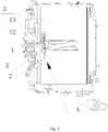
- the present embodiment provides a drum washing machine which includes an inner drum 3, wherein an inner drum bottom cover 1 is installed on the drum bottom of the inner drum 3, and the inner drum bottom cover 1 is in sealed connection with a surface of the inner drum to form a sealed space.
- washing water is difficult to remove after entering a chamber formed between the inner drum bottom cover 1 and the drum bottom of the inner drum.
- the existing manners for cleaning the inner drum include current scouring, washing with a hairbrush, and using cleaning particles, etc.
- washing objectives cannot be achieved through the above inner drum cleaning methods.
- washing water will be deposited under the inner drum bottom cover for a long time, thereby causing such problems of breeding of bacteria and generation of smudge.
- the inner drum bottom cover and the drum bottom of the inner drum are directly connected in a sealed manner to form a sealed chamber, thereby fundamentally stopping washing water from entering a chamber formed between the inner drum bottom cover and the drum bottom of the inner drum, and solving the problem that clothes washed for the next time are polluted by bacteria bred due to long-time deposition of washing water in the inner drum.
- the drum bottom of the inner drum is fixed on a tripod 2 via a bolt or penetrates through a bolt hole on the tripod 2 and is fixed on a flange plate, and the inner drum bottom cover 1 of a washing machine is fixed on the drum bottom of the inner drum via a screw 12 to cover a bolt on the drum bottom of the inner drum, and forms a chamber with the drum bottom of the inner drum.
- waste water cannot be discharged after entering the chamber, and bacteria are easily bred after long-time accumulation of waste water. Then when clothes are washed for the next time, clothes are easily polluted.
- the inner drum bottom cover is in sealed connection with the drum bottom of the inner drum, thereby stopping waste water from entering the inner drum.
- the center of the drum bottom of the inner drum 3 is sunken inwards to form a groove, a bolt hole is formed at the bottom of the groove, and a sealed chamber for accommodating a bolt are formed by the inner drum bottom cover 1 and the groove in a sealed manner.
- the drum bottom of the inner drum is fixed on the tripod 2 by six bolts which are arranged circularly or penetrates through the bolt hole on the tripod 2 via bolts and is fixed on a flange plate.
- One side, facing towards the drum bottom of the inner drum, of the inner drum bottom cover 1 is provided with, corresponding to each bolt, an accommodation chamber 11 which is used for accommodating and evading screws.
- the accommodation chamber 11 covers the bolt, and the end face of the accommodation chamber is also in sealed connection with the drum bottom of the inner drum, thereby preventing washing water from entering the inner space via the bolt.
- the inner drum bottom cover 1 of a washing machine is of a disc structure, buckled on the drum bottom of the inner drum, and is fixed on the drum bottom of the inner drum via screw 12. Since the inner drum bottom cover 1 is fixed on the drum bottom of the inner drum via a screw, washing water may also enter a chamber formed between the inner drum bottom cover 1 and the drum bottom of the inner drum along a screw 12, therefore, in the present embodiment, two parts of the inner drum bottom cover need to be sealed.
- the first sealing part is an outer circumference of the inner drum bottom cover 1, and the second sealing part is at the screw hole in the center of the inner drum bottom cover.
- the circumference surface of the inner drum bottom cover and the screw hole are both in sealed connection with the drum bottom of the inner drum via a sealing element.
- the sealing element is a seal ring
- the inner drum bottom cover 1 is in sealed connection with the drum bottom of the inner drum via a seal ring to realize sealing.
- sealing treatment can be performed between the screw and the screw hole, and can also be performed through setting a sealed structure around a screw hole.
- the sealed effect is better when sealed connection is realized through sealing between a screw and a screw hole as well as sealing through setting a sealed structure around the screw hole.
- the center of the inner drum bottom cover 1 is provided with a screw hole 13, and the inner drum bottom cover is fixed on the drum bottom of the inner drum by screws through the screw hole.
- the inner drum bottom cover 1 is concentrically provided with multiple circular convex ribs extending into the drum bottom of the inner drum.
- the outmost circular convex rib 15 is in sealed connection with the drum bottom of the inner drum, and the circular convex ribs on the periphery of the screw hole is in sealed connection with the drum bottom of the inner drum.
- the periphery of the screw hole may be provided with multiple circular convex ribs, and in the present embodiment, preferably, the circular convex rib which is closest to the periphery of the screw hole is in sealed connection with the drum bottom of the inner drum to realize sealing.
- sealing of the inner drum bottom cover is not limited to sealing via a circular convex rib, and other structures which can realize sealing are also applicable herein.
- each circular convex rib is concentrically set with the screw hole, the end face of the outmost circular convex rib 15 is in sealed connection with the drum bottom of the inner drum, and the end part of a innermost circular convex rib 14 is in sealed connection with the drum bottom of the inner drum.
- the outmost circular convex rib 15 is preferably set on an outer circumference of the inner drum bottom cover, and this structure is an optimal waterproof structure.
- an end face of the outmost circular convex rib 15 is compacted with the drum bottom of the inner drum 3 via a seal ring for sealed connection
- the center of the drum bottom of the inner drum is provided with a screw base for assembling a screw 12
- the inner surface of an end part of the innermost circular convex rib 14 is compacted with an outer wall of the screw base via a seal ring for sealed connection.
- the inner drum bottom cover 1 of a washing machine in the present embodiment is provided with a structure which is used for fixing a seal ring.
- a groove 4 is respectively arranged on an end face of a outmost circular convex rib 15 and on the inner surface of an end part of a innermost circular convex rib 14, and the seal ring is accommodated in the groove 4 and extends out of the groove to be in sealed contact with a surface of the inner drum; and further preferably, at least one ring of grooves are arranged respectively on the end face of the outmost circular convex rib 15 and the inner surface of an end part of a innermost circular convex rib 14, and each ring of grooves are correspondingly set with a seal ring;
- the seal ring in the present disclosure can be subjected to diversity design, and the grooves 4 can also be diversified accordingly. More preferably, multiple rings of grooves are respectively arranged on the end face of the outmost circular convex rib 15 and the inner surface of an end part of the innermost circular convex rib 14, and multiple rings of grooves correspond to one seal ring.
- One side of the seal ring is provided with protruding parts which respectively correspond to each groove, and the other side is in sealed connection with the drum bottom of the inner drum. Multiple grooves correspond to one seal ring, therefore, installation process can be simplified, and initial installation can be finished after directly installing the seal ring in multiple corresponding grooves.
- the width of the protruding part of the seal ring is slightly greater than the width of a groove, then when a seal ring is installed in a groove, an effect that the seal ring is connected in a groove in an automatically compacted manner is produced, therefore, the connection between the seal ring and the groove is firmer.
- the lifting rib of a washing machine is set to be a structure which is isolated from inner space of the inner drum in a sealed manner.
- the lifting rib 5 is a shell with an opening, the surface of the shell is not provided with a through hole, the opening end of the shell is in sealed connection with the drum wall of the inner drum.
- the opening end is provided with a groove 4, the groove 4 accommodates a seal ring, and the seal ring is accommodated in the groove 4 and extends out of the groove to be in sealed contact with the surface of the inner drum.
- the lifting rib 5 is fixed on the drum bottom of the inner drum via a screw and/or a clip connecting piece, and under the pressure of the screw and/or clip connecting piece, the seal ring is arranged between the groove and the drum wall of the inner drum in a compressed manner by the lifting rib 5.
- the lifting rib 5 is provided with an installation chamber, clip connecting pieces 6 are arranged around the installation chamber, and clip seats are correspondingly arranged on the drum wall of the inner drum of a washing machine, so as to perform clamping positioning on the lifting rib 5.
- the installation chamber is also provided with a lifting rib screw base 7 which extends towards the drum bottom of the inner drum of a washing machine, and the inner drum bottom cover is fixed on the drum wall of the inner drum of a washing machine by screws through the screw hole.
- a lifting rib screw base 7 which extends towards the drum bottom of the inner drum of a washing machine
- the inner drum bottom cover is fixed on the drum wall of the inner drum of a washing machine by screws through the screw hole.
- an opening end of a shell of a lifting rib 5 can be provided with a ring of grooves 4 which are matched with the seal ring, the groove 4 is internally provided with a seal ring, and the seal ring protrudes out of the groove to be compressed between the groove and the inner drum of a washing machine.
- the opening end of a shell of a lifting rib can be provided with multiple rings of grooves which are arranged in parallel, wherein each groove respectively corresponds to one seal ring or all the grooves commonly correspond to one seal ring, and when all the grooves commonly correspond to one seal ring, the structure of the seal ring is slightly complex, with one side of the seal ring being provided with protruding parts which are respectively accommodated in each groove, while the other side being in sealed contact with the drum wall of the inner drum.
- an opening end of a shell of the lifting rib is provided with two rings of grooves
- the seal ring includes two protruding parts which are respectively accommodated within the groove and a connecting part which is configured to connect the protruding parts
- the connecting part is configured between the opening end of a shell of a lifting rib and the drum wall of the inner drum in a compressed manner, thereby preventing water inside the inner drum of a washing machine from entering inside the shell of a lifting rib, since long-time accumulation of waste water inside the lifting rib may breed bacteria and harm health.
- the lifting rib 5 of the inner drum of a washing machine in the present embodiment can be set to be integrated with the inner drum, for example, the lifting rib 5 of a washing machine is formed through stamping from the drum wall to a central axis of the inner drum, then the lifting rib inside a washing machine is not provided with a chamber for accommodating laundry waste water, thereby achieving the purpose of zero pollution during second clothes washing of the lifting rib.
- the lifting rib in the present embodiment can also be set to be a solid structure, then an accommodation chamber which accommodates laundry waste water is not provided, thereby avoiding long-time deposition of washing water inside the lifting rib, and breeding of bacteria and generation of smudge are avoided.
- the lifting rib is arranged to be a solid structure, then the weight of the inner drum is increased, and materials with low density and high hardness need to be selected. Therefore, in order to lower difficulty, in the present embodiment, the lifting rib can be set to be a sealed hollow structure, then the weight of the lifting rib can be reduced, and long-time deposition of washing water in the lifting rib can be avoided, thereby avoiding breeding bacteria and generating smudge.
- the present embodiment differs from the above embodiments as follows: in the present embodiment, all the internal accessories of the inner drum are set to be structures which are isolated from the inner space of the inner drum in a sealed manner, wherein accessories of the inner drum mainly include a lifting rib 5 and the inner drum bottom cover 1.
- the inner drum bottom cover adopts the technical solution in embodiment 1, embodiment 2 or embodiment 3 or adopts the technical solution of any combination of the above three embodiments, while a lifting rib of the inner drum in the present embodiment adopts the technical solution in embodiment 4.
- the lifting rib and the inner drum bottom cover are simultaneously set to be a structure sealed with the inner drum, thereby basically ensuring that internal environment of the inner drum of a washing machine is clean and no pollution is generated.
Landscapes
- Engineering & Computer Science (AREA)
- Textile Engineering (AREA)
- Main Body Construction Of Washing Machines And Laundry Dryers (AREA)
- Accessory Of Washing/Drying Machine, Commercial Washing/Drying Machine, Other Washing/Drying Machine (AREA)
Applications Claiming Priority (2)
| Application Number | Priority Date | Filing Date | Title |
|---|---|---|---|
| CN201611121227.7A CN108179591B (zh) | 2016-12-08 | 2016-12-08 | 一种洗衣机 |
| PCT/CN2017/114982 WO2018103690A1 (zh) | 2016-12-08 | 2017-12-07 | 一种洗衣机 |
Publications (2)
| Publication Number | Publication Date |
|---|---|
| EP3553217A1 true EP3553217A1 (de) | 2019-10-16 |
| EP3553217A4 EP3553217A4 (de) | 2019-11-20 |
Family
ID=62490712
Family Applications (1)
| Application Number | Title | Priority Date | Filing Date |
|---|---|---|---|
| EP17877571.4A Withdrawn EP3553217A4 (de) | 2016-12-08 | 2017-12-07 | Waschmaschine |
Country Status (4)
| Country | Link |
|---|---|
| US (1) | US11091868B2 (de) |
| EP (1) | EP3553217A4 (de) |
| CN (1) | CN108179591B (de) |
| WO (1) | WO2018103690A1 (de) |
Family Cites Families (18)
| Publication number | Priority date | Publication date | Assignee | Title |
|---|---|---|---|---|
| FR1352933A (fr) * | 1963-01-08 | 1964-02-21 | Thomson Houston Comp Francaise | Perfectionnements apportés aux machines à laver à panier horizontal |
| KR19980046029U (ko) * | 1996-12-27 | 1998-09-25 | 배순훈 | 세탁기의 펄세이터 조인트 실링장치 |
| JP3197840B2 (ja) | 1997-03-31 | 2001-08-13 | 三洋電機株式会社 | 衣類乾燥機 |
| JP4854206B2 (ja) | 2005-02-17 | 2012-01-18 | 株式会社東芝 | ドラム式洗濯機 |
| JP5025628B2 (ja) | 2008-12-17 | 2012-09-12 | 株式会社東芝 | 洗濯機 |
| US9758919B2 (en) * | 2010-08-09 | 2017-09-12 | Lg Electronics Inc. | Apparatus for treating laundry |
| US9096965B2 (en) | 2010-08-09 | 2015-08-04 | Lg Electronics Inc. | Apparatus for treating laundry having a ring shaped circular guide |
| CN102268800A (zh) * | 2011-05-31 | 2011-12-07 | 任文涛 | 分类洗单桶滚筒洗衣机 |
| CN102733147B (zh) * | 2012-06-08 | 2017-09-29 | 青岛海尔洗衣机有限公司 | 一种具有自清洁桶壁功能的洗衣机内桶及洗衣机 |
| IN2014MN02440A (de) | 2012-06-08 | 2015-07-10 | Haier Group Corp | |
| KR101568914B1 (ko) | 2013-12-24 | 2015-11-12 | 동부대우전자 주식회사 | 세탁기 |
| CN204298639U (zh) * | 2014-10-31 | 2015-04-29 | 青岛海尔洗衣机有限公司 | 一种洗衣机内桶 |
| CN105887425B (zh) * | 2015-01-26 | 2019-11-12 | 青岛海尔洗衣机有限公司 | 一种洗衣机判断、控制水位的方法和装置 |
| CN106192295B (zh) * | 2015-05-05 | 2019-04-19 | 青岛海尔洗衣机有限公司 | 一种洗衣机内桶轴密封安装结构 |
| CN106939485B (zh) * | 2015-10-02 | 2019-08-09 | Lg电子株式会社 | 顶部装载型洗衣机 |
| CN205347800U (zh) * | 2015-12-29 | 2016-06-29 | Tcl家用电器(合肥)有限公司 | 洗衣机内筒法兰组件、洗衣机内筒和洗衣机 |
| CN107201627B (zh) | 2016-03-16 | 2020-04-21 | 天津海尔洗涤电器有限公司 | 一种洗衣机内桶及洗衣机 |
| CN205711422U (zh) * | 2016-03-23 | 2016-11-23 | Tcl智能科技(合肥)有限公司 | 洗衣机内筒组件及滚筒洗衣机 |
-
2016
- 2016-12-08 CN CN201611121227.7A patent/CN108179591B/zh active Active
-
2017
- 2017-12-07 WO PCT/CN2017/114982 patent/WO2018103690A1/zh not_active Ceased
- 2017-12-07 EP EP17877571.4A patent/EP3553217A4/de not_active Withdrawn
- 2017-12-07 US US16/466,437 patent/US11091868B2/en active Active
Also Published As
| Publication number | Publication date |
|---|---|
| US11091868B2 (en) | 2021-08-17 |
| US20190309461A1 (en) | 2019-10-10 |
| WO2018103690A1 (zh) | 2018-06-14 |
| CN108179591A (zh) | 2018-06-19 |
| EP3553217A4 (de) | 2019-11-20 |
| CN108179591B (zh) | 2021-10-08 |
Similar Documents
| Publication | Publication Date | Title |
|---|---|---|
| CN107475986B (zh) | 洗衣机 | |
| CN215605385U (zh) | 一种吸尘器中的防溅罩 | |
| CN111041769B (zh) | 一种滚筒洗衣机的控制方法及滚筒洗衣机 | |
| EP3733950A1 (de) | Waschanlage und waschwasserablaufverfahren | |
| WO2019056671A1 (zh) | 洗衣机 | |
| CN107938259A (zh) | 一种洗衣机的干扰抑制装置及洗衣机 | |
| US11091868B2 (en) | Washing machine | |
| CN107475993B (zh) | 洗衣机 | |
| CN108729102B (zh) | 一种洗衣机 | |
| CN108611806B (zh) | 一种内筒底及洗衣机 | |
| US20180298545A1 (en) | Washing machine inner barrel and washing machine | |
| CN111041758B (zh) | 一种滚筒洗衣机 | |
| CN110230164A (zh) | 一种洗衣机 | |
| JP2021532946A (ja) | 洗濯機 | |
| JP2021500187A (ja) | 洗濯機用の回転槽ユニット及び洗濯機用ダンパーを備える洗濯機 | |
| CN105544149A (zh) | 一种电机及装有上述电机的洗涤装置 | |
| CN110952269A (zh) | 一种滚筒洗衣机 | |
| CN109097951B (zh) | 洗衣机 | |
| JP2020527405A (ja) | 洗濯機 | |
| WO2023011506A1 (zh) | 一种进水组件及洗衣机 | |
| CN106702671B (zh) | 洗衣机及其小桶组件 | |
| US20200399812A1 (en) | Washing machine | |
| CN107713950B (zh) | 洗碗机及洗碗机的加盐盖 | |
| CN119800661A (zh) | 一种洗衣机 | |
| CN206477145U (zh) | 洗衣机及其小桶组件 |
Legal Events
| Date | Code | Title | Description |
|---|---|---|---|
| STAA | Information on the status of an ep patent application or granted ep patent |
Free format text: STATUS: THE INTERNATIONAL PUBLICATION HAS BEEN MADE |
|
| PUAI | Public reference made under article 153(3) epc to a published international application that has entered the european phase |
Free format text: ORIGINAL CODE: 0009012 |
|
| STAA | Information on the status of an ep patent application or granted ep patent |
Free format text: STATUS: REQUEST FOR EXAMINATION WAS MADE |
|
| 17P | Request for examination filed |
Effective date: 20190626 |
|
| AK | Designated contracting states |
Kind code of ref document: A1 Designated state(s): AL AT BE BG CH CY CZ DE DK EE ES FI FR GB GR HR HU IE IS IT LI LT LU LV MC MK MT NL NO PL PT RO RS SE SI SK SM TR |
|
| AX | Request for extension of the european patent |
Extension state: BA ME |
|
| A4 | Supplementary search report drawn up and despatched |
Effective date: 20191021 |
|
| RIC1 | Information provided on ipc code assigned before grant |
Ipc: D06F 37/02 20060101AFI20191015BHEP Ipc: D06F 37/06 20060101ALN20191015BHEP |
|
| DAV | Request for validation of the european patent (deleted) | ||
| DAX | Request for extension of the european patent (deleted) | ||
| STAA | Information on the status of an ep patent application or granted ep patent |
Free format text: STATUS: THE APPLICATION IS DEEMED TO BE WITHDRAWN |
|
| 18D | Application deemed to be withdrawn |
Effective date: 20200603 |