EP3553033A1 - Appareil de traitement d'eau de ballast et système de traitement d'eau de ballast - Google Patents
Appareil de traitement d'eau de ballast et système de traitement d'eau de ballast Download PDFInfo
- Publication number
- EP3553033A1 EP3553033A1 EP18167319.5A EP18167319A EP3553033A1 EP 3553033 A1 EP3553033 A1 EP 3553033A1 EP 18167319 A EP18167319 A EP 18167319A EP 3553033 A1 EP3553033 A1 EP 3553033A1
- Authority
- EP
- European Patent Office
- Prior art keywords
- ballast water
- injector
- treatment apparatus
- water treatment
- gas
- Prior art date
- Legal status (The legal status is an assumption and is not a legal conclusion. Google has not performed a legal analysis and makes no representation as to the accuracy of the status listed.)
- Withdrawn
Links
- XLYOFNOQVPJJNP-UHFFFAOYSA-N water Substances O XLYOFNOQVPJJNP-UHFFFAOYSA-N 0.000 title claims abstract description 149
- 238000011282 treatment Methods 0.000 title claims abstract description 68
- 239000007789 gas Substances 0.000 claims abstract description 119
- 239000007788 liquid Substances 0.000 claims abstract description 17
- QVGXLLKOCUKJST-UHFFFAOYSA-N atomic oxygen Chemical compound [O] QVGXLLKOCUKJST-UHFFFAOYSA-N 0.000 claims abstract description 4
- 239000001301 oxygen Substances 0.000 claims abstract description 4
- 229910052760 oxygen Inorganic materials 0.000 claims abstract description 4
- 230000002829 reductive effect Effects 0.000 claims description 5
- 238000001035 drying Methods 0.000 claims description 4
- 239000008239 natural water Substances 0.000 claims description 4
- 239000007800 oxidant agent Substances 0.000 description 19
- 238000004659 sterilization and disinfection Methods 0.000 description 17
- 238000000034 method Methods 0.000 description 16
- 241000195493 Cryptophyta Species 0.000 description 10
- 230000008569 process Effects 0.000 description 10
- 230000004888 barrier function Effects 0.000 description 8
- CBENFWSGALASAD-UHFFFAOYSA-N Ozone Chemical compound [O-][O+]=O CBENFWSGALASAD-UHFFFAOYSA-N 0.000 description 7
- 238000004519 manufacturing process Methods 0.000 description 7
- 230000001590 oxidative effect Effects 0.000 description 7
- 241000894007 species Species 0.000 description 7
- 238000001914 filtration Methods 0.000 description 6
- 235000002639 sodium chloride Nutrition 0.000 description 6
- ZAMOUSCENKQFHK-UHFFFAOYSA-N Chlorine atom Chemical compound [Cl] ZAMOUSCENKQFHK-UHFFFAOYSA-N 0.000 description 5
- 239000000460 chlorine Substances 0.000 description 5
- 229910052801 chlorine Inorganic materials 0.000 description 5
- FAPWRFPIFSIZLT-UHFFFAOYSA-M Sodium chloride Chemical compound [Na+].[Cl-] FAPWRFPIFSIZLT-UHFFFAOYSA-M 0.000 description 4
- 238000002156 mixing Methods 0.000 description 4
- 239000011780 sodium chloride Substances 0.000 description 4
- 239000000243 solution Substances 0.000 description 4
- 230000003068 static effect Effects 0.000 description 4
- 230000001133 acceleration Effects 0.000 description 3
- 230000000694 effects Effects 0.000 description 3
- 238000005868 electrolysis reaction Methods 0.000 description 3
- 230000000670 limiting effect Effects 0.000 description 3
- GRYLNZFGIOXLOG-UHFFFAOYSA-N Nitric acid Chemical compound O[N+]([O-])=O GRYLNZFGIOXLOG-UHFFFAOYSA-N 0.000 description 2
- VYPSYNLAJGMNEJ-UHFFFAOYSA-N Silicium dioxide Chemical compound O=[Si]=O VYPSYNLAJGMNEJ-UHFFFAOYSA-N 0.000 description 2
- 230000003139 buffering effect Effects 0.000 description 2
- 238000011088 calibration curve Methods 0.000 description 2
- 238000006555 catalytic reaction Methods 0.000 description 2
- 238000005660 chlorination reaction Methods 0.000 description 2
- 150000001805 chlorine compounds Chemical class 0.000 description 2
- 238000010586 diagram Methods 0.000 description 2
- 238000007599 discharging Methods 0.000 description 2
- 231100001261 hazardous Toxicity 0.000 description 2
- 230000036541 health Effects 0.000 description 2
- 230000006872 improvement Effects 0.000 description 2
- 239000000203 mixture Substances 0.000 description 2
- 229910017604 nitric acid Inorganic materials 0.000 description 2
- 230000036961 partial effect Effects 0.000 description 2
- 230000009467 reduction Effects 0.000 description 2
- 150000003839 salts Chemical class 0.000 description 2
- 101000588924 Anthopleura elegantissima Delta-actitoxin-Ael1a Proteins 0.000 description 1
- UFHFLCQGNIYNRP-UHFFFAOYSA-N Hydrogen Chemical compound [H][H] UFHFLCQGNIYNRP-UHFFFAOYSA-N 0.000 description 1
- 241000196321 Tetraselmis Species 0.000 description 1
- 241000405713 Tetraselmis suecica Species 0.000 description 1
- GWEVSGVZZGPLCZ-UHFFFAOYSA-N Titan oxide Chemical class O=[Ti]=O GWEVSGVZZGPLCZ-UHFFFAOYSA-N 0.000 description 1
- 230000009471 action Effects 0.000 description 1
- 230000002411 adverse Effects 0.000 description 1
- PNEYBMLMFCGWSK-UHFFFAOYSA-N aluminium oxide Inorganic materials [O-2].[O-2].[O-2].[Al+3].[Al+3] PNEYBMLMFCGWSK-UHFFFAOYSA-N 0.000 description 1
- 239000008346 aqueous phase Substances 0.000 description 1
- 238000005452 bending Methods 0.000 description 1
- 230000033228 biological regulation Effects 0.000 description 1
- 239000006227 byproduct Substances 0.000 description 1
- 230000008859 change Effects 0.000 description 1
- 238000006243 chemical reaction Methods 0.000 description 1
- 239000003795 chemical substances by application Substances 0.000 description 1
- 229930002875 chlorophyll Natural products 0.000 description 1
- 235000019804 chlorophyll Nutrition 0.000 description 1
- ATNHDLDRLWWWCB-AENOIHSZSA-M chlorophyll a Chemical compound C1([C@@H](C(=O)OC)C(=O)C2=C3C)=C2N2C3=CC(C(CC)=C3C)=[N+]4C3=CC3=C(C=C)C(C)=C5N3[Mg-2]42[N+]2=C1[C@@H](CCC(=O)OC\C=C(/C)CCC[C@H](C)CCC[C@H](C)CCCC(C)C)[C@H](C)C2=C5 ATNHDLDRLWWWCB-AENOIHSZSA-M 0.000 description 1
- 235000009508 confectionery Nutrition 0.000 description 1
- 238000009792 diffusion process Methods 0.000 description 1
- 239000012895 dilution Substances 0.000 description 1
- 238000010790 dilution Methods 0.000 description 1
- 238000009826 distribution Methods 0.000 description 1
- 238000005265 energy consumption Methods 0.000 description 1
- 239000001257 hydrogen Substances 0.000 description 1
- 229910052739 hydrogen Inorganic materials 0.000 description 1
- 238000005286 illumination Methods 0.000 description 1
- 238000011065 in-situ storage Methods 0.000 description 1
- 238000002347 injection Methods 0.000 description 1
- 239000007924 injection Substances 0.000 description 1
- 238000009434 installation Methods 0.000 description 1
- 238000009413 insulation Methods 0.000 description 1
- 230000003993 interaction Effects 0.000 description 1
- 150000002500 ions Chemical class 0.000 description 1
- 238000005259 measurement Methods 0.000 description 1
- 230000007246 mechanism Effects 0.000 description 1
- 239000012528 membrane Substances 0.000 description 1
- 230000003287 optical effect Effects 0.000 description 1
- 238000006385 ozonation reaction Methods 0.000 description 1
- 239000002245 particle Substances 0.000 description 1
- 230000000243 photosynthetic effect Effects 0.000 description 1
- 230000035790 physiological processes and functions Effects 0.000 description 1
- 239000000047 product Substances 0.000 description 1
- 230000035484 reaction time Effects 0.000 description 1
- 230000001850 reproductive effect Effects 0.000 description 1
- 239000013535 sea water Substances 0.000 description 1
- 239000004065 semiconductor Substances 0.000 description 1
- 238000000926 separation method Methods 0.000 description 1
- 239000007787 solid Substances 0.000 description 1
- 230000006641 stabilisation Effects 0.000 description 1
- 238000011105 stabilization Methods 0.000 description 1
- 238000003860 storage Methods 0.000 description 1
- 239000000126 substance Substances 0.000 description 1
- 238000002604 ultrasonography Methods 0.000 description 1
- 238000012800 visualization Methods 0.000 description 1
- 239000000037 vitreous enamel Substances 0.000 description 1
Images

Classifications
-
- C—CHEMISTRY; METALLURGY
- C02—TREATMENT OF WATER, WASTE WATER, SEWAGE, OR SLUDGE
- C02F—TREATMENT OF WATER, WASTE WATER, SEWAGE, OR SLUDGE
- C02F1/00—Treatment of water, waste water, or sewage
- C02F1/72—Treatment of water, waste water, or sewage by oxidation
-
- B—PERFORMING OPERATIONS; TRANSPORTING
- B01—PHYSICAL OR CHEMICAL PROCESSES OR APPARATUS IN GENERAL
- B01F—MIXING, e.g. DISSOLVING, EMULSIFYING OR DISPERSING
- B01F23/00—Mixing according to the phases to be mixed, e.g. dispersing or emulsifying
- B01F23/20—Mixing gases with liquids
- B01F23/23—Mixing gases with liquids by introducing gases into liquid media, e.g. for producing aerated liquids
- B01F23/232—Mixing gases with liquids by introducing gases into liquid media, e.g. for producing aerated liquids using flow-mixing means for introducing the gases, e.g. baffles
- B01F23/2323—Mixing gases with liquids by introducing gases into liquid media, e.g. for producing aerated liquids using flow-mixing means for introducing the gases, e.g. baffles by circulating the flow in guiding constructions or conduits
-
- B—PERFORMING OPERATIONS; TRANSPORTING
- B01—PHYSICAL OR CHEMICAL PROCESSES OR APPARATUS IN GENERAL
- B01F—MIXING, e.g. DISSOLVING, EMULSIFYING OR DISPERSING
- B01F25/00—Flow mixers; Mixers for falling materials, e.g. solid particles
- B01F25/30—Injector mixers
- B01F25/31—Injector mixers in conduits or tubes through which the main component flows
- B01F25/312—Injector mixers in conduits or tubes through which the main component flows with Venturi elements; Details thereof
- B01F25/3124—Injector mixers in conduits or tubes through which the main component flows with Venturi elements; Details thereof characterised by the place of introduction of the main flow
- B01F25/31242—Injector mixers in conduits or tubes through which the main component flows with Venturi elements; Details thereof characterised by the place of introduction of the main flow the main flow being injected in the central area of the venturi, creating an aspiration in the circumferential part of the conduit
-
- B—PERFORMING OPERATIONS; TRANSPORTING
- B01—PHYSICAL OR CHEMICAL PROCESSES OR APPARATUS IN GENERAL
- B01F—MIXING, e.g. DISSOLVING, EMULSIFYING OR DISPERSING
- B01F25/00—Flow mixers; Mixers for falling materials, e.g. solid particles
- B01F25/30—Injector mixers
- B01F25/31—Injector mixers in conduits or tubes through which the main component flows
- B01F25/312—Injector mixers in conduits or tubes through which the main component flows with Venturi elements; Details thereof
- B01F25/3125—Injector mixers in conduits or tubes through which the main component flows with Venturi elements; Details thereof characteristics of the Venturi parts
- B01F25/31251—Throats
-
- B—PERFORMING OPERATIONS; TRANSPORTING
- B63—SHIPS OR OTHER WATERBORNE VESSELS; RELATED EQUIPMENT
- B63J—AUXILIARIES ON VESSELS
- B63J4/00—Arrangements of installations for treating ballast water, waste water, sewage, sludge, or refuse, or for preventing environmental pollution not otherwise provided for
- B63J4/002—Arrangements of installations for treating ballast water, waste water, sewage, sludge, or refuse, or for preventing environmental pollution not otherwise provided for for treating ballast water
-
- C—CHEMISTRY; METALLURGY
- C01—INORGANIC CHEMISTRY
- C01B—NON-METALLIC ELEMENTS; COMPOUNDS THEREOF; METALLOIDS OR COMPOUNDS THEREOF NOT COVERED BY SUBCLASS C01C
- C01B13/00—Oxygen; Ozone; Oxides or hydroxides in general
- C01B13/10—Preparation of ozone
-
- C—CHEMISTRY; METALLURGY
- C02—TREATMENT OF WATER, WASTE WATER, SEWAGE, OR SLUDGE
- C02F—TREATMENT OF WATER, WASTE WATER, SEWAGE, OR SLUDGE
- C02F1/00—Treatment of water, waste water, or sewage
- C02F1/72—Treatment of water, waste water, or sewage by oxidation
- C02F1/78—Treatment of water, waste water, or sewage by oxidation with ozone
-
- B—PERFORMING OPERATIONS; TRANSPORTING
- B01—PHYSICAL OR CHEMICAL PROCESSES OR APPARATUS IN GENERAL
- B01F—MIXING, e.g. DISSOLVING, EMULSIFYING OR DISPERSING
- B01F2101/00—Mixing characterised by the nature of the mixed materials or by the application field
- B01F2101/305—Treatment of water, waste water or sewage
-
- C—CHEMISTRY; METALLURGY
- C02—TREATMENT OF WATER, WASTE WATER, SEWAGE, OR SLUDGE
- C02F—TREATMENT OF WATER, WASTE WATER, SEWAGE, OR SLUDGE
- C02F2103/00—Nature of the water, waste water, sewage or sludge to be treated
- C02F2103/008—Originating from marine vessels, ships and boats, e.g. bilge water or ballast water
-
- C—CHEMISTRY; METALLURGY
- C02—TREATMENT OF WATER, WASTE WATER, SEWAGE, OR SLUDGE
- C02F—TREATMENT OF WATER, WASTE WATER, SEWAGE, OR SLUDGE
- C02F2303/00—Specific treatment goals
- C02F2303/04—Disinfection
-
- C—CHEMISTRY; METALLURGY
- C02—TREATMENT OF WATER, WASTE WATER, SEWAGE, OR SLUDGE
- C02F—TREATMENT OF WATER, WASTE WATER, SEWAGE, OR SLUDGE
- C02F2305/00—Use of specific compounds during water treatment
- C02F2305/02—Specific form of oxidant
- C02F2305/023—Reactive oxygen species, singlet oxygen, OH radical
-
- Y—GENERAL TAGGING OF NEW TECHNOLOGICAL DEVELOPMENTS; GENERAL TAGGING OF CROSS-SECTIONAL TECHNOLOGIES SPANNING OVER SEVERAL SECTIONS OF THE IPC; TECHNICAL SUBJECTS COVERED BY FORMER USPC CROSS-REFERENCE ART COLLECTIONS [XRACs] AND DIGESTS
- Y02—TECHNOLOGIES OR APPLICATIONS FOR MITIGATION OR ADAPTATION AGAINST CLIMATE CHANGE
- Y02A—TECHNOLOGIES FOR ADAPTATION TO CLIMATE CHANGE
- Y02A90/00—Technologies having an indirect contribution to adaptation to climate change
- Y02A90/40—Monitoring or fighting invasive species
Definitions
- the present disclosure relates to a ballast water treatment apparatus and to a ballast water treatment system.
- ballast water tank For travelling in a partially loaded or unloaded state, a cargo ship is typically equipped with one or more ballast water tank.
- the ballast water tanks are filled with seawater (saline water) at a first location which contributes to stabilization. The ship travels to a second location and discharges the ballast water.
- Ballast water from the first location may contain biological species such as algae and oceanic plankton that are biologically invasive (i. e. introduced species) at the second location.
- a typical ballast water treatment process involves a filtration stage (a physical separation stage) and a disinfection stage.
- a filtration stage typically, solids having a particle size of >50 ⁇ m are removed.
- Examples for a filtration stage include back-washable mesh or disk filters, hydrocyclones or the like. Living organisms below these dimensions remain to be treated by the disinfection stage.
- UV treatment Most commonly, the disinfection stage involves an ultraviolet (UV) treatment method or an electro-chlorination method. Regulations in some countries require that organisms released in a ballast water discharging process are actually dead; however, UV treatment is known to leave some organisms in a living, but non-viable stage. As the UV treatment mainly damages the DNA of organisms, it can render them non-reproductive. However, to actually kill the organisms, very high doses of UV are necessary, which leads to large energy consumption and reduces the treatment capacity of a UV-based disinfection stage. Some UV-based disinfection stage treatment methods involve a first disinfection process during charging the ballast water into the ballast water tanks, and a second disinfection process during the ballast water discharge, which makes this approach time consuming.
- UV-based disinfection stage treatment methods involve a first disinfection process during charging the ballast water into the ballast water tanks, and a second disinfection process during the ballast water discharge, which makes this approach time consuming.
- Electro-chlorination is an electrolytic process that needs a branch path, or side-stream path, branching off from the main ballast water stream. Electrolysis in saline water generates free chlorine that is an active oxidative species. The electrolyzed branched-off water is injected into the main ballast water, wherein the free chlorine and/or chlorine compounds generated therefrom disrupt the outer membrane of the living organisms inside the ballast water stream.
- free chlorine as well as some chlorine compounds are known to have long lifetime; thus, such substances have to be removed prior to discharging the treated water into the sea.
- electrolysis is non-functional in brackish water or sweet water. Also, the level of salinity of the treated water directly affects the chlorine production. Moreover, electrolysis involves a production of hydrogen as a by-product, which may lead to security risks.
- a ballast water treatment apparatus comprises a ballast water transport line and a plasma generation device.
- the ballast water transport line is configured to transport ballast water between a first location and a second location.
- the transported ballast water is passed through at least one injector.
- the plasma generation device is configured to be fed with a feed gas comprising oxygen.
- the plasma generation device is further configured to generate a feed gas plasma by a non-thermal discharge in a discharge area in order to provide a treated gas at a treated-gas outlet.
- the injector comprises a liquid passage.
- the liquid passage is constructed such as to increase a velocity of the passed-through water in a region of increased velocity.
- the injector further comprises an injector gas inlet that is provided in the region of increased velocity.
- the treated-gas outlet is in gaseous connection with the injector gas inlet.
- An injector is generally a device having the liquid passage for passing through the ballast water, and the injector gas inlet at which a gas provided at the injector gas inlet is sucked into the passed-through ballast water stream.
- the injector makes use of Bernoulli's principle to achieve the region of increased velocity, which is a region of reduced static pressure compared to the static pressure at the inlet of the injector.
- One example of an injector comprises a bent or curved pipe in order to achieve the velocity change of the passed-through ballast water.
- a Venturi injector is used as the injector according to the present disclosure.
- a Venturi injector applicable to the present application is obtainable from Mazzei Injector Company, LLC, Bakersfield, CA, US, e. g. as Injector Model 484, for relatively low volume rates per hour.
- An injector working according to the same principle may be appropriately chosen for higher volume rates per hour of the passed-through ballast water according to the specific need.
- volume rates per hour that the present application is applicable to can be greater than 100 m 3 /h, for example greater than 500 m 3 /h and about 1000 m 3 /h, but not limited thereto.
- Transporting between the first location and the second location generally comprises selectively transporting from the first location to the second location, or from the second location to the first location. However, the transporting may also be limited to either transporting from the first location to the second location or from the second location to the first location.
- the first location is a natural water reservoir such as a saline water body, or the first location is in connection with such a natural water reservoir.
- the second location is a part of a seaborne ballast water system, such as a ballast water tank of a seagoing vessel.
- the non-thermal discharge is a dielectric barrier discharge (DBD), a corona type discharge or an arc-less discharge fed by a pulsed energy source.
- DBD dielectric barrier discharge
- Non-thermal involves generally a discharge in which no arcing occurs.
- a dielectric for producing the dielectric barrier discharge may be, but is not limited to, silica glass, quartz glass, alumina, and vitreous enamel.
- at least one electrode of the plasma generation device is at least partially covered with the dielectric.
- a non-thermal discharge such as a streamer-type discharge, is different from an arc-type discharge and different from a corona-type discharge.
- a dielectric barrier discharge occurs as a fast ionizing front mechanism (the 'streamer' regime): An ionization is stimulated by an avalanche of electrons which leads to a distribution of carrier charges by the avalanche.
- a streamer head having a high charge moves forward inside the generated field. The field is shielded by the streamer head (i.e. the most of the field drops off in the streamer head region) and the streamer moves in the overall field.
- the described electron acceleration processes and ionization is taking place.
- the plasma is generated as a non-equilibrium (non-LTE) plasma.
- the electrical energy of the discharge is primarily transferred to electrons that are elevated in temperature (e. g. to temperatures of more than 103 K), whereas the heavier gas components (atoms, molecules, ions) stay at temperatures close to the ambient temperature of e. g. ⁇ 400 K.
- the electrons at the elevated temperature inelastically collide with the heavier gas components.
- active oxidants are produced.
- An active oxidant may, for example, include ozone, but also excited molecules and radicals.
- Active oxidants exhibit a comparatively short effective lifetime.
- Ozone has a lifetime that is, in the aqueous phase, short compared to the lifetime of chlorine.
- the treated gas at the treated-gas outlet is provided substantially without any buffering, in particular entirely without any buffering, i. e. without being stored in a tank or the like. Rather, the treated gas is introduced, by the gaseous connection between the treated-gas outlet of the plasma generation device and the injector gas inlet of the injector, directly into the ballast water transport line.
- the treatment in the ballast water treatment apparatus described herein is effective in view of the disinfection performance and the degree of utilization of the active oxidants produced by the plasma generation device.
- substantially the entirety of ballast water typically the entirety of ballast water, that is transported by the ballast water treatment apparatus is transported through the at least one injector.
- substantially the entirety of ballast water typically the entirety of ballast water, that is transported by the ballast water treatment apparatus is transported through the at least one injector.
- more than 99.9% of the ballast water that is transported by the ballast water treatment apparatus is transported through the at least one injector.
- no branch line or bypass line is provided in the ballast water treatment apparatus.
- a gas pressure in the discharge area is reduced to within a range of 0.2 p BW to 0.9 p BW , optionally within a range of 0.5 p BW to 0.8 p BW , wherein p BW is the pressure (i.e. water pressure) inside the ballast water transport line.
- p BW is the pressure (i.e. water pressure) inside the ballast water transport line.
- the static pressure in the discharge area is about 250 kPa.
- the amount of active oxidants such as ozone
- the pressure is reduced with respect to the pressure that exists in the ballast water transport line.
- the pressure reduction is typically due to the Bernoulli Effect inherent to injectors such as Venturi-type injectors.
- a pressure reduction of the gas in the discharge area allows for a non-thermal discharge that produces a suitable amount of active oxidants at a comparatively low voltage, leading to low losses e. g. in the semiconductors used for voltage generation and to lower insulation requirements.
- a power supply provides a (pulsed) voltage of approximately 10 kV.
- a typical pressure of the ballast water inside the ballast water transport line amounts to approximately 350-500 kPa.
- the plasma generation device comprises a discharge pipe configured to have the feed gas passed through a feed gas passage.
- the discharge area is arranged in the feed gas passage.
- the feed gas passage has a uniform diameter throughout the elongation of the discharge area.
- a discharge pipe can have a cylindrical coaxial geometry, a plate to plate geometry or other possible geometries.
- a discharge pipe has an internal electrode, such as an electrode wire, that is on high voltage potential, and an external grounded electrode.
- the external grounded electrode may be a laminar electrode arranged on a wall of a cylindrical support structure of the discharge pipe.
- a discharge pipe has two laminar electrodes, each electrode being arranged on the outside of a cylindrical support structure of the discharge pipe.
- the inner electrode can be arranged on the inside of the inner dielectric cylinder leading to a system with two dielectric barriers. The high voltage potential is applied to one of the electrodes.
- the cylindrical support structure may be the dielectric involved in the non-thermal discharge such as the dielectric barrier discharge.
- a discharge pipe may contribute to a simple arrangement in which the treated gas is effectively injected into the ballast water stream.
- the treated-gas outlet of the discharge pipe opens out into the constricted area of the liquid passage of the injector and is arranged to provide a tangential component of the treated gas flowing out of the treated-gas outlet with respect to the water passed through the liquid passage of the injector.
- a tangential component can be achieved, for example, by tilting the treated-gas outlet or by bending the discharge pipe in the region of the treated-gas outlet. Then, the gas flow trajectory in the feed gas passage, as well as the gas flowing out of the treated-gas outlet in the vicinity of the treated-gas outlet, have a tangential component to the water flow.
- a tangential injection is advantageous for the pressure drop and does not adversely affect the mixing efficiency.
- the treated-gas outlet of the discharge pipe is arranged at a distance of less than 100 mm from the passed-through water.
- the treated-gas outlet of the discharge pipe is arranged at a distance of less than 80 mm and more than 5 mm from the passed-through water.
- the treated-gas outlet of the discharge pipe is arranged at a distance of less than 50 mm and more than 5 mm from the passed-through water.
- the treated-gas outlet or exit of the plasma generation device is positioned in a proximity of the ballast water stream which shall be disinfected during the ballast water transportation process, the proximity fulfilling the conditions disclosed herein. This may help to provide a suitable density of active oxidants to interact with the water stream, which then leads to an efficient oxidative disinfection.
- a cross sectional distance, e. g. a radial cross sectional diameter, of the feed gas passage of the discharge pipe has a value between 0.5 mm and 8 mm, optionally between 0.5 mm and 5 mm and preferably approximately 1 mm.
- a radial gaseous gap is of the order of between 0.5 mm and 8 mm, preferably approximately 1 mm. This may help to achieve an advantageous critical voltage, or threshold voltage, for the onset of the plasma in the non-thermal discharge.
- an absolute value of an amplitude of a voltage applied to obtain the non-thermal discharge is between 1 kV and 30 kV, optionally between 3 kV and 15 kV.
- a voltage applied to obtain the non-thermal discharge is a pulsed voltage, wherein the pulsed voltage has a pulse frequency between 5 kHz and 200 kHz, optionally between 10 kHz and 100 kHz and typically about 10 kHz.
- the pulsed voltage when the voltage applied to obtain the non-thermal discharge is a pulsed voltage, such as a unipolar or bipolar pulsed voltage, the pulsed voltage has a pulse duration between 0.1 ⁇ s and 5 ⁇ s, optionally between 1 ⁇ s and 3 ⁇ s and preferably about 1 ⁇ s.
- the ballast water treatment apparatus comprises multiple Venturi injectors.
- the multiple injectors are connected in parallel.
- each injector comprises one injector gas inlet or multiple injector gas inlets, as described further below.
- a parallel configuration may help to effectively mix the treated gas even when the total amount of water per unit time that is transported through the ballast water transport line is high.
- multiple injectors may also be connected in series. For example, multiple parallel branches of series-connected injectors may be provided.
- At least one injector comprises multiple injector gas inlets.
- the multiple injector gas inlets are arranged and connected according to a circular pattern or a helical pattern along a circumference of the ballast water transport line. Multiple injector gas inlets may contribute to an effective mixing of the treated gas and the transported ballast water.
- the ballast water treatment apparatus comprises multiple plasma generation devices which are each assigned to one or more of the injector gas inlets.
- each injector in the case of multiple injectors has assigned a different one of the multiple plasma generation devices; alternatively, multiple injectors are grouped, and each group has assigned a different one of the multiple plasma generation device.
- each injector gas inlet has assigned a different one of the multiple plasma generation devices; alternatively, some injector gas inlets of the one injector are grouped, and each group has assigned a different one of the multiple plasma generation device.
- the ballast water treatment apparatus comprises a voltage generator supplying one or more of the multiple plasma generation devices and at least one further generator supplying a different one or different ones of the multiple plasma generation devices.
- the voltage generator has a voltage parameter that is adjustable independent from a corresponding voltage parameter of the further voltage generator.
- a voltage parameter may include an absolute value of the output voltage, a pulse frequency of the output voltage, and/or a pulse duration of the output voltage.
- the ballast water treatment apparatus further comprises a feed gas drying device.
- the feed gas such as air
- the feed gas may be dried to a dew point below -40 °C, typically below -70 °C.
- a dry feed gas generation of specific undesired molecules can be avoided.
- Radicals stemming from e. g. humid air as a feed gas may include nitric acid (HNO 3 ), which is relatively stable, highly corrosive and biologically hazardous.
- HNO 3 nitric acid
- ozone that is created in higher concentration with dry air is known to self-degrade to non-hazardous molecules in a relatively short period of time, which may be advantageous to shorten a ballast water discharge time after the disinfection in the disinfection stage is complete.
- a ballast water system comprises a ballast water treatment apparatus as described herein and a ballast water tank.
- the first location is in liquid connection with a natural water reservoir.
- the second location is in liquid connection with the ballast water tank.
- a liquid connection allows liquids to pass through the connection.
- Injecting the effluent of a non-thermal plasma permits a well-controlled in-situ production of active oxidants, regardless of the ballast water conditions, e.g. its salinity, turbidity, temperature etc. This is an improvement over electrolytic or UV-catalytic ballast water disinfection in which the water to be treated will influence the production of oxidants.
- the presently described configuration also has an improvement over the case where the plasma (either non-equilibrium or thermalized) is ignited directly inside the water to be treated; in that a case, an additional disadvantage is that the electric load will strongly vary with the water quality thus challenging the robustness of the process.
- Pulses may be unipolar pulses or bipolar pulses, i. e. pulses changing the polarity of the voltage alternatingly.
- the treated-gas outlet is placed in the proximity of the water stream. This significantly reduces fouling processes, such as due to interaction with the ballast, in contrast to the UV or UV-enhanced catalysis disinfection methods in the conventional prior art. Furthermore, this permits to make use of short-lived oxidants for the disinfection action. In other methods where the oxidants have a rather long life-time, the respective oxidant generation stage is placed in a distance larger by orders of magnitude, and has to be buffered. However, in the present configuration the plasma is ignited in direct vicinity to the water to be treated.
- the disclosed solution allows installation of the system without significant pressure drop, thereby increasing the efficiency and making retrofit applications possible.
- Fig. 1 is a schematic view of a ballast water treatment apparatus 100 according to an embodiment of the present disclosure.
- a ballast water transport line 10 is provided between a first location A and a second location B.
- the first location A is a natural sea body such as an ocean;
- the second location B is exemplified as a storage part of a ballast water system 1, for example, the second location B is the inside of a ballast water tank.
- a filtration stage may be arranged for filtering the water from the first location A flowing into the ballast water treatment apparatus 100. Also, a filtration stage may be part of the presently described the ballast water treatment apparatus 100.
- an injector 20 such as a Venturi injector.
- the injector 20 includes a liquid passage 21 through which the ballast water that is to be transported between the first location A and the second location B is passed through.
- the liquid passage 21 has a constricted area 22 that is constructed such that a velocity of the passed-through ballast water is increased within a region 26 of increased velocity.
- An inlet allowing for the introduction of a gas to be mixed with the passed-through ballast water referred to as an injector gas inlet 25 (see Fig. 2, 3 ), is provided in the region 26 of increased velocity.
- the presently described configuration allows for under-dimensioning a gas supply pump (not shown) for supplying a feed gas. Additionally, turbulences occurring in the region 26 of increased velocity contribute to a fast mixing of gas sucked in at the injector gas inlet 25. Furthermore, the present configuration creates virtually no large phase-separated regions. In addition, very small bubbles of the sucked gas are created inside the ballast water stream, which advantageously lead to an improved diffusion of the active oxidants into the transported ballast water.
- a plasma generation device 30 is further provided.
- the plasma generation device 30 is fed with a feed gas, preferably with a feed gas that comprises oxygen (O 2 ).
- a feed gas include dry air or technically dried air, but are not limited thereto.
- a feed gas drying device 60 is provided that technically dries the feed gas, e. g. air, to have a dew point below -40 °C.
- the plasma generation device 30 in the embodiment depicted in Fig. 1 is constructed as a discharge pipe 38 having a gas gap 31 of about 1 mm, and includes a high voltage electrode 32 and a ground electrode 33. It is noted that the ground electrode may also be the electrode 32, and the high voltage electrode may also be the electrode 33. For the sake of convenience, herein and as exemplary embodiment only, the electrode 32 is assumed to be on a (pulsed) high voltage potential, and the electrode 33 is grounded.
- a support structure of the plasma generation device 30 forms a dielectric barrier 34 between the high voltage electrode 32 and the ground electrode 33. Between the high voltage electrode 32 and dielectric barrier 34, a discharge area 36 is formed in which, upon application of a high voltage between the electrodes 32, 33, a streamer-type plasma 35 is induced. The plasma 35 leads to a generation of a treated gas that is provided at a treated-gas outlet 37.
- a high voltage pulse generator 50 is provided that is in electrical connection with the electrodes 33, 34.
- the pulse generator 50 is configured to provide high voltage pulses having an absolute value of about 10 kV between the electrodes 33, 34.
- the treated gas comprises, among others, ozone (O 3 ) as an active oxidant.
- the treated-gas outlet 37 is arranged to be in a gaseous connection with the injector gas inlet 25. Thereby, upon transportation of ballast water through the transport line 10 and the Venturi injector 20, the Venturi injector 20 forms a "jet&mix" structure in which the treated gas is effectively mixed and distributed inside the ballast water stream.
- the treated-gas outlet 37 is arranged at a distance of approximately 50-80 mm from the stream of the passed-through water in the acceleration region or region of increased water stream velocity 26. Thereby, a suitable amount of active oxidants, such as ozone, is available to interact with the water stream.
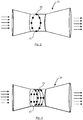
- Figs. 2 and 3 each are schematic side views of a Venturi injector 20 used in an embodiment of the present disclosure.
- the Venturi injector 20 has multiple injector gas inlets 25 that are schematically depicted as circles.
- two injector gas inlets 25 have been assigned a reference numeral for sake of simplicity; however, it is understood that each of the circles represents one of the multiple gas inlets 25.
- the connecting lines between the circles are for visualization purposes only.
- the number of multiple injector gas inlets 25 is not limited to that shown in Figs. 2 or 3 , and different numbers of multiple injector gas inlets 25 can be used.
- the multiple injector gas inlets 25 in Fig. 2 are arranged in a circular pattern.
- the multiple injector gas inlets 25 are arranged in a helical or cylindrical pattern. These arrangements may help to ensure an advantageous mixing of the treated gas and the ballast water.
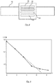
- Fig. 4 is a schematic partial view of a ballast water treatment apparatus 100 according to an embodiment of the present disclosure.
- the ballast water treatment apparatus 100 comprises a ballast water transport line 10 and multiple Venturi injectors 20 stacked in a parallel configuration.
- Fig. 4 not all components of the ballast water treatment apparatus 100 are shown, and the further components are, for example, present, in particular arranged and configured, as in the embodiment shown in Fig. 1 .
- the number of multiple injectors 20 is not limited to that shown in Fig. 4 , and different numbers of multiple injectors 20 may be used.
- Fig. 5 is a diagram showing experimental treatment results for a biological species that has undergone a treatment by a ballast water treatment apparatus as disclosed herein.
- the abscissa shows a number of treatments applied to a solution containing the biological species, and the ordinate shows the concentration of the biological species within the solution per milliliter.
- Similar results as shown in Fig. 5 are obtainable by varying the voltage pulse frequency instead of increasing the number of treatments, for example.
- a number of treatments may also be achieved by multiple injectors 20 connected in series.
- the measurement results in Fig. 5 may assist in defining an optimal configuration, for example by changing the treatment strength (number of treatments, voltage pulse frequency and the like) shown on the abscissa.
- a Marine micro algae organism Tetraselmis suecica
- the algae cultures were maintained at 20-22 °C with constant air flow.
- a calibration curve was created.
- a set of standard dilutions from the stock algae solution with salt water using marine salt, e.g. Tetra marine sea salt) was first prepared. Then, the cell concentration was determined using direct microscopic cell counts. For that, an improved Neubauer cell counting chamber was used. 25-50 ⁇ l of Lugol's fixation agent was added to the sample prior to microscopic observation. Thereafter, the OJIP (fluorescence curve of chlorophyll) and optical density (OD) were measured by using a fluorimeter (AquaPen-C AP-C 100, Photo Systems Instruments Inc.). The samples were kept in the dark for 10 minutes before measuring OJIP.
Landscapes
- Chemical & Material Sciences (AREA)
- Engineering & Computer Science (AREA)
- Chemical Kinetics & Catalysis (AREA)
- Organic Chemistry (AREA)
- Environmental & Geological Engineering (AREA)
- General Health & Medical Sciences (AREA)
- Mechanical Engineering (AREA)
- Health & Medical Sciences (AREA)
- Life Sciences & Earth Sciences (AREA)
- Public Health (AREA)
- Toxicology (AREA)
- Combustion & Propulsion (AREA)
- Water Supply & Treatment (AREA)
- Ocean & Marine Engineering (AREA)
- Hydrology & Water Resources (AREA)
- Inorganic Chemistry (AREA)
- Physical Water Treatments (AREA)
- Treatment Of Water By Oxidation Or Reduction (AREA)
- Water Treatment By Electricity Or Magnetism (AREA)
Priority Applications (5)
| Application Number | Priority Date | Filing Date | Title |
|---|---|---|---|
| EP18167319.5A EP3553033A1 (fr) | 2018-04-13 | 2018-04-13 | Appareil de traitement d'eau de ballast et système de traitement d'eau de ballast |
| PCT/EP2019/059500 WO2019197649A1 (fr) | 2018-04-13 | 2019-04-12 | Appareil et procédé de traitement d'eaux de ballast |
| CN201980033658.3A CN112154126A (zh) | 2018-04-13 | 2019-04-12 | 压载水处理设备和压载水处理系统 |
| EP19717882.5A EP3774669B1 (fr) | 2018-04-13 | 2019-04-12 | Appareil de traitement d'eau de ballast et système de traitement d'eau de ballast |
| US17/069,114 US11577812B2 (en) | 2018-04-13 | 2020-10-13 | Ballast water treatment apparatus and ballast water treatment system |
Applications Claiming Priority (1)
| Application Number | Priority Date | Filing Date | Title |
|---|---|---|---|
| EP18167319.5A EP3553033A1 (fr) | 2018-04-13 | 2018-04-13 | Appareil de traitement d'eau de ballast et système de traitement d'eau de ballast |
Publications (1)
| Publication Number | Publication Date |
|---|---|
| EP3553033A1 true EP3553033A1 (fr) | 2019-10-16 |
Family
ID=62002010
Family Applications (2)
| Application Number | Title | Priority Date | Filing Date |
|---|---|---|---|
| EP18167319.5A Withdrawn EP3553033A1 (fr) | 2018-04-13 | 2018-04-13 | Appareil de traitement d'eau de ballast et système de traitement d'eau de ballast |
| EP19717882.5A Active EP3774669B1 (fr) | 2018-04-13 | 2019-04-12 | Appareil de traitement d'eau de ballast et système de traitement d'eau de ballast |
Family Applications After (1)
| Application Number | Title | Priority Date | Filing Date |
|---|---|---|---|
| EP19717882.5A Active EP3774669B1 (fr) | 2018-04-13 | 2019-04-12 | Appareil de traitement d'eau de ballast et système de traitement d'eau de ballast |
Country Status (4)
| Country | Link |
|---|---|
| US (1) | US11577812B2 (fr) |
| EP (2) | EP3553033A1 (fr) |
| CN (1) | CN112154126A (fr) |
| WO (1) | WO2019197649A1 (fr) |
Cited By (1)
| Publication number | Priority date | Publication date | Assignee | Title |
|---|---|---|---|---|
| WO2022006037A1 (fr) | 2020-06-30 | 2022-01-06 | Onvector, Llc | Système et procédé de traitement de l'eau au moyen de décharge de plasma venturi |
Families Citing this family (4)
| Publication number | Priority date | Publication date | Assignee | Title |
|---|---|---|---|---|
| US11492274B2 (en) * | 2020-05-28 | 2022-11-08 | National Chiao Tung University | Liquid treatment apparatus |
| KR102502054B1 (ko) * | 2022-07-21 | 2023-02-22 | (주)이엠씨 | 모듈타입의 조립체를 구비한 선박용 플라즈마 밸러스트수 처리장치 |
| CN116634645B (zh) * | 2023-01-16 | 2026-03-24 | 费勉仪器科技(上海)有限公司 | 等离子液体活化装置 |
| CN116395784A (zh) * | 2023-04-25 | 2023-07-07 | 深圳先进技术研究院 | 一种基于空化等离子体技术的医疗废水处理装置 |
Citations (2)
| Publication number | Priority date | Publication date | Assignee | Title |
|---|---|---|---|---|
| CN102689974A (zh) * | 2010-11-20 | 2012-09-26 | 大连海事大学 | 一种氧活性粒子处理污水的设备 |
| KR20170121425A (ko) * | 2016-04-25 | 2017-11-02 | 주식회사 엔팩 | 플라즈마 수처리 장치 |
Family Cites Families (18)
| Publication number | Priority date | Publication date | Assignee | Title |
|---|---|---|---|---|
| US20030015481A1 (en) * | 2001-06-28 | 2003-01-23 | Eidem Ola Magne | Method and apparatus for treating/disinfecting ballast water in ships |
| CN1197786C (zh) * | 2003-06-13 | 2005-04-20 | 大连海事大学 | 在船上输送压载水过程中杀灭生物的方法及设备 |
| CA2595734C (fr) * | 2005-01-24 | 2010-02-16 | Nutech O3, Inc. | Procede et systeme d'injection d'ozone |
| CN100415412C (zh) * | 2005-09-30 | 2008-09-03 | 中国工程物理研究院激光聚变研究中心 | 有机包覆金属纳米粉末的制备方法及其装置 |
| DE102006027677A1 (de) * | 2006-06-14 | 2008-01-10 | Siemens Ag | Verfahren zur Reduzierung von Verunreinigungen in einem Wassersystem bei der Herstellung von Flächengebilden |
| CN100519439C (zh) * | 2006-10-25 | 2009-07-29 | 浙江工业大学 | 臭氧与高压电晕联用处理高浓度有机废水的方法及设备 |
| EP2146933A4 (fr) * | 2007-04-10 | 2012-02-29 | Samkun Century Co Ltd | Dispositif de traitement à plasma sous-marin et système et procédé de traitement d'eau de ballast d'un navire au moyen de ce dispositif |
| CN102803152B (zh) * | 2009-05-29 | 2014-10-15 | H·布卢姆 | 用丙烯醛处理压舱水的方法和设备 |
| US9073766B2 (en) * | 2009-08-25 | 2015-07-07 | Fahs Stagemyer, Llc | Methods for the treatment of ballast water |
| CN201907997U (zh) * | 2010-11-20 | 2011-07-27 | 大连海事大学 | 一种氧活性粒子治理赤潮的装置 |
| CN102501945A (zh) * | 2011-11-17 | 2012-06-20 | 扬州大洋造船有限公司 | 远洋船舶压载水处理装置 |
| CN103922459A (zh) * | 2014-04-27 | 2014-07-16 | 大连海事大学 | 一种水力空化协同高浓度活性氧制备羟自由基的方法 |
| JP6322477B2 (ja) * | 2014-05-20 | 2018-05-09 | 国立大学法人 熊本大学 | 有機物含有水の処理装置及び方法 |
| CN204142465U (zh) * | 2014-09-01 | 2015-02-04 | 江苏大学 | 一种气液两相流相含率控制及气液两相混合装置 |
| ES2869598T3 (es) * | 2014-12-15 | 2021-10-25 | Vitalfluid B V | Sistema de reactor de agua activado por plasma térmico y no térmico |
| CN205101083U (zh) * | 2015-11-19 | 2016-03-23 | 大连海事大学 | 一种应用于船用柴油机scr系统自激振荡脉冲雾化喷嘴 |
| JP6671683B2 (ja) * | 2016-03-28 | 2020-03-25 | 日本スピンドル製造株式会社 | 液状物質の殺菌方法及び装置 |
| EP3666736A1 (fr) * | 2018-12-14 | 2020-06-17 | ABB Schweiz AG | Appareil de traitement d'eau de ballast et procédé pour le traitement d'eau de ballast |
-
2018
- 2018-04-13 EP EP18167319.5A patent/EP3553033A1/fr not_active Withdrawn
-
2019
- 2019-04-12 EP EP19717882.5A patent/EP3774669B1/fr active Active
- 2019-04-12 WO PCT/EP2019/059500 patent/WO2019197649A1/fr not_active Ceased
- 2019-04-12 CN CN201980033658.3A patent/CN112154126A/zh active Pending
-
2020
- 2020-10-13 US US17/069,114 patent/US11577812B2/en active Active
Patent Citations (2)
| Publication number | Priority date | Publication date | Assignee | Title |
|---|---|---|---|---|
| CN102689974A (zh) * | 2010-11-20 | 2012-09-26 | 大连海事大学 | 一种氧活性粒子处理污水的设备 |
| KR20170121425A (ko) * | 2016-04-25 | 2017-11-02 | 주식회사 엔팩 | 플라즈마 수처리 장치 |
Non-Patent Citations (2)
| Title |
|---|
| KEN-ICHI KUDO ET AL: "Oxidative DNA damage caused by pulsed discharge with cavitation on the bactericidal function", JOURNAL OF PHYSICS D: APPLIED PHYSICS, INSTITUTE OF PHYSICS PUBLISHING LTD, GB, vol. 48, no. 36, 12 August 2015 (2015-08-12), pages 365401, XP020289214, ISSN: 0022-3727, [retrieved on 20150812], DOI: 10.1088/0022-3727/48/36/365401 * |
| XIANGYING MENG ET AL: "Treatment of Microalgae in Ballast Water Using Hydroxyl Radical in Accordance with the D-2 Ballast Water Discharge Standard", HIGH VOLTAGE ENGINEERING, vol. 40, no. 1, 31 January 2014 (2014-01-31), pages 232 - 236, XP055495165, ISSN: 1003-6520, DOI: 10.13336/j.1003-6520.hve.2014.01.034 * |
Cited By (4)
| Publication number | Priority date | Publication date | Assignee | Title |
|---|---|---|---|---|
| WO2022006037A1 (fr) | 2020-06-30 | 2022-01-06 | Onvector, Llc | Système et procédé de traitement de l'eau au moyen de décharge de plasma venturi |
| JP2023532307A (ja) * | 2020-06-30 | 2023-07-27 | オンベクター・エル・エル・シー | ベンチュリプラズマ放電を用いた水処理のためのシステム及び方法 |
| EP4172107A4 (fr) * | 2020-06-30 | 2023-11-29 | Onvector, LLC | Système et procédé de traitement de l'eau au moyen de décharge de plasma venturi |
| IL299485B1 (en) * | 2020-06-30 | 2026-02-01 | Onvector Llc | System and method for treating water with venturi plasma discharge |
Also Published As
| Publication number | Publication date |
|---|---|
| CN112154126A (zh) | 2020-12-29 |
| WO2019197649A1 (fr) | 2019-10-17 |
| US20210031896A1 (en) | 2021-02-04 |
| EP3774669A1 (fr) | 2021-02-17 |
| EP3774669B1 (fr) | 2024-03-20 |
| US11577812B2 (en) | 2023-02-14 |
Similar Documents
| Publication | Publication Date | Title |
|---|---|---|
| US11577812B2 (en) | Ballast water treatment apparatus and ballast water treatment system | |
| US9352984B2 (en) | Fluid treatment using plasma technology | |
| Wang et al. | Micro hollow cathode excited dielectric barrier discharge (DBD) plasma bubble and the application in organic wastewater treatment | |
| JP5099612B2 (ja) | 液体処理装置 | |
| WO2008047084A2 (fr) | Procédés et appareil de traitement de liquide | |
| EP3894360B1 (fr) | Dispositif de traitement d'eau et procédé pour le traitement d'eau | |
| US20150139853A1 (en) | Method and apparatus for transforming a liquid stream into plasma and eliminating pathogens therein | |
| US20250002376A1 (en) | Plasma water treatment | |
| US9409800B2 (en) | Electric arc for aqueous fluid treatment | |
| US12264083B2 (en) | Water treatment system and method for treatment of water | |
| CN111115773A (zh) | 气液固三相脉冲放电水处理系统及其处理方法 | |
| CN111137957A (zh) | 气液固三相脉冲放电电气特性研究实验装置及其方法 | |
| RU2478580C1 (ru) | Устройство для обеззараживания стоков электрическими разрядами | |
| CN102050510A (zh) | 一种船舶压载水处理方法和设备 | |
| Sone et al. | Sterilization of E. coli in Seawater using Discharge in water and Dielectric Barrier Discharge | |
| El Shaer et al. | Effect of Water Parameters on Decolourization Efficiency of Organic Dyes by Dielectric Barrier Discharge Plasma | |
| Pandiyaraj et al. | Non-thermal atmospheric pressure plasma jet-assisted degradation of azo dye–acid orange 7 (AO7): influence of operating parameters and toxicity evaluation | |
| RU189390U1 (ru) | Плазмогазокаталитический реактор обработки жидкости | |
| Lukes et al. | Bulk-phase chemistry induced by nanosecond discharge plasma in water | |
| WO2016182548A1 (fr) | Arc électrique pour traitement de fluides aqueux | |
| EP3981743A1 (fr) | Procédé et dispositif de désinfection de liquide | |
| Hosano et al. | Effect of Gas Bubbling on the Physical and Chemical Activity of High Voltage Discharge Plasma in Water | |
| KR20250158605A (ko) | 파동형 축전식탈염 기반의 자기장 및 전기장을 기반으로 하는 마이크로 플라즈마 aop 수처리 장치 및 방법 | |
| Mok | PURIFICATION OF DYEING WASTEWATER BY USING ELECTRICAL DISCHARGE PLASMA. | |
| Miron et al. | Spectroscopic investigations of chemical reactions in liquids plasma |
Legal Events
| Date | Code | Title | Description |
|---|---|---|---|
| PUAI | Public reference made under article 153(3) epc to a published international application that has entered the european phase |
Free format text: ORIGINAL CODE: 0009012 |
|
| AK | Designated contracting states |
Kind code of ref document: A1 Designated state(s): AL AT BE BG CH CY CZ DE DK EE ES FI FR GB GR HR HU IE IS IT LI LT LU LV MC MK MT NL NO PL PT RO RS SE SI SK SM TR |
|
| AX | Request for extension of the european patent |
Extension state: BA ME |
|
| STAA | Information on the status of an ep patent application or granted ep patent |
Free format text: STATUS: THE APPLICATION IS DEEMED TO BE WITHDRAWN |
|
| 18D | Application deemed to be withdrawn |
Effective date: 20200603 |