EP3552979B1 - Preparation of multilayer packages - Google Patents
Preparation of multilayer packages Download PDFInfo
- Publication number
- EP3552979B1 EP3552979B1 EP19156456.6A EP19156456A EP3552979B1 EP 3552979 B1 EP3552979 B1 EP 3552979B1 EP 19156456 A EP19156456 A EP 19156456A EP 3552979 B1 EP3552979 B1 EP 3552979B1
- Authority
- EP
- European Patent Office
- Prior art keywords
- film
- sealing
- transport direction
- accordance
- packaging machine
- Prior art date
- Legal status (The legal status is an assumption and is not a legal conclusion. Google has not performed a legal analysis and makes no representation as to the accuracy of the status listed.)
- Not-in-force
Links
Images
Classifications
-
- B—PERFORMING OPERATIONS; TRANSPORTING
- B65—CONVEYING; PACKING; STORING; HANDLING THIN OR FILAMENTARY MATERIAL
- B65B—MACHINES, APPARATUS OR DEVICES FOR, OR METHODS OF, PACKAGING ARTICLES OR MATERIALS; UNPACKING
- B65B9/00—Enclosing successive articles, or quantities of material, e.g. liquids or semiliquids, in flat, folded, or tubular webs of flexible sheet material; Subdividing filled flexible tubes to form packages
- B65B9/02—Enclosing successive articles, or quantities of material between opposed webs
-
- B—PERFORMING OPERATIONS; TRANSPORTING
- B65—CONVEYING; PACKING; STORING; HANDLING THIN OR FILAMENTARY MATERIAL
- B65B—MACHINES, APPARATUS OR DEVICES FOR, OR METHODS OF, PACKAGING ARTICLES OR MATERIALS; UNPACKING
- B65B25/00—Packaging other articles presenting special problems
- B65B25/06—Packaging slices or specially-shaped pieces of meat, cheese, or other plastic or tacky products
- B65B25/08—Packaging slices or specially-shaped pieces of meat, cheese, or other plastic or tacky products between layers or strips of sheet or web material, e.g. in webs folded to zig-zag form
-
- B—PERFORMING OPERATIONS; TRANSPORTING
- B65—CONVEYING; PACKING; STORING; HANDLING THIN OR FILAMENTARY MATERIAL
- B65B—MACHINES, APPARATUS OR DEVICES FOR, OR METHODS OF, PACKAGING ARTICLES OR MATERIALS; UNPACKING
- B65B31/00—Packaging articles or materials under special atmospheric or gaseous conditions; Adding propellants to aerosol containers
- B65B31/02—Filling, closing, or filling and closing, containers or wrappers in chambers maintained under vacuum or superatmospheric pressure or containing a special atmosphere, e.g. of inert gas
Definitions
- the invention relates to a packaging machine, in particular for food products, with several workstations arranged one behind the other along a transport direction for the production of multi-layer packs from a lower film, an upper film and at least one intermediate film, the lower film with the central film being a lower product layer and the upper film with the or a further central film encloses an upper product layer of a respective pack, the films each having a product area and laterally adjacent to the product area edge areas running parallel to the transport direction.
- the invention also relates to a method for producing such multi-layer packs.
- the invention also relates to uses of certain films in such a packaging machine and / or in such a method.
- the invention also relates to a multi-layer pack which is produced or can be produced by such a packaging machine and / or which is obtained or obtainable by such a method.
- multi-layer packs for example for packaging food products
- multi-layer packs at least two products lie on top of one another, with two product layers lying directly on top of one another being separated from one another by a central film.
- the middle foils are also sometimes called intermediate foils or - just like the top one Foil of the pack - referred to as top foils.
- all of the films located between the lowest film (the lower film) and the uppermost film (the upper film) are each referred to as the middle film.
- film webs are used, each of which has a web width to which the packaging machine must be adapted.
- the edge areas of the foils are used to connect the foils to one another by sealing.
- the edge areas of the foils can be provided with perforations through which the product layers are accessible in order to evacuate the product layers and to fill them with a protective gas.
- a gas exchange is often preferred in practice, but in principle not mandatory. In some applications it is sufficient to simply evacuate the product layers before the final sealing. If gas exchange is desired, evacuation and gassing can take place one after the other, for example through the same perforations. Usually, however, different holes are used for evacuation and gassing.
- both the application of vacuum and / or gas and the final closing of the product layers usually take place in a single work station, which is referred to as the sealing station, since the closing of the product layers and thus the final closing of the multi-layer pack is carried out by sealing.
- This end seal surrounding the product areas which is in the In practice, also referred to as a sealing seam, lies within the perforations of the edge areas, since the perforated sections of the edge areas are then separated - usually in a work station connected to the sealing station.
- the packs are usually provided with a label in practice.
- the products forming the lower product layer are placed on the product area of the lower film that is fed to the machine on the input side.
- the central film is fed downstream of the product depositing point, thereby enclosing the lower product layer.
- the central film is often fixed to the lower film in order to ensure a correct relative position between the central film and the lower film during further transport in the packaging machine. This fixing is usually done by what is known as sealing, in which the middle film and the lower film are attached to one another by forming sealing points.
- sealing does not yet represent a gas-tight end seal, but rather serves - as mentioned - only to fix the two films to one another.
- the products forming the upper product layer are then placed on the middle film, specifically at those points where the first product layer was previously placed. Further product layers and middle films can then be applied in order to produce multi-layer packs with more than two product layers lying one above the other.
- such packaging machines are operated cyclically.
- the film webs are moved by one working length in the transport direction, the working length corresponding to the length measured in the transport direction of at least one pack.
- this working length also referred to as the preferred or format length, is usually n times the length of a pack, possibly plus scrap between two immediately consecutive packs, where n is the number of packs following one another in the transport direction in a respective format.
- the top film is fed in so that the top or top product layer is also enclosed.
- the at least three film webs with the enclosed product layers then reach the sealing station already mentioned, in which the product layers are subjected to vacuum and / or gas through the perforations in the edge areas of the films and are finally sealed.
- the lower film often has to be reshaped in order to form shell-like lower packaging parts.
- the lower film must pass through a so-called deep-drawing station on the packaging machine.
- each central film is narrower than the lower film and than the upper film, so that the perforations of the lower film are not overlapped by the central film. This means that it is not necessary to punch holes in the middle foils.
- a comparatively simple sealing as mentioned above, is not possible, since the middle foils each do not have a sufficiently wide edge area for this.
- all product layers must be evacuated and / or gassed via the perforations formed in the lower film. In many cases, advantageous individual treatment of the product layers during evacuation and / or gassing, in each case with direct access to the relevant product layer, is then not possible.
- the evacuation and / or gassing takes place again exclusively via perforations in the lower film, with the edge regions of the middle films overlapping the edge regions and thus the perforations in the lower film.
- the middle foils are also perforated here, with the resulting openings each having to be provided with a seal in order to ensure a gas-tight passage through the respective foils involved.
- the object of the invention is to create a possibility of producing multi-layer packs as simply as possible, with the packaging machine used for this purpose in particular having the simplest possible structure and in particular the shortest possible machine length.
- a work station is a sealing station which is designed to apply vacuum and / or gas to the product layers through perforations in the edge areas of the upper film and the lower film and then to close them by sealing the films
- the sealing station being a comprises the upper evacuation and / or gassing tool aligned with the perforation of the upper film and a lower evacuation and / or gassing tool aligned with the perforation of the lower film
- a further work station being a sealing station located upstream of the sealing station, which is designed to attach the central film to seal the lower film to a seal located in the edge areas, and wherein the lower evacuation and / or gassing tool of the sealing station and a sealing tool of the sealing station serving to produce the seal on a common, parallel to the transport direction ve running working line.
- the packaging machine is designed to produce a seal during operation on overlapping edge areas of foils transported in the transport direction and to interact with a perforation, the sealing and the perforation in the same transverse position, ie on a common, parallel to the transport direction running line or within a strip running parallel to the transport direction, the width of which is not greater than the width of the edge areas.
- This embodiment of the packaging machine according to the invention does not rule out a common or independent adjustability of the tools transversely to the transport direction, even for other applications.
- vacuum and / or gas are applied to the product layers through perforations in the edge areas of the upper film and the lower film and then closed by sealing the films, the application of vacuum and / or gas taking place, while the unperforated edge region of the The middle film and the perforated edge areas of the lower film and the upper film overlap one another, and the lower product layer is acted upon by the perforation of the lower film and the upper product layer is acted upon through the perforation of the upper film.
- the edge area of the middle film can overlap the edge areas of the lower film and the upper film and does not need to be perforated if the sealing station of the packaging machine is designed to pass the upper product layer through the upper film and the lower product layer through the lower film to apply.
- a work station for perforating the central film can therefore be saved.
- the packaging machine can therefore be shortened by at least one working length and thus cycle length.
- a further simplification of the packaging machine results from the fact that no seals have to be formed on the perforations of the lower film and the upper film, since the perforation of the lower film only has to provide access to the lower product layer and the perforation of the upper film only has to provide access to the upper product layer.
- the ability of the sealing station according to the invention to act on the superimposed foils both from below and from above for evacuation and / or gassing increases the expenditure for the construction and operation of the sealing station and the packaging machine overall, however, only apparently. This is because the lower tool and the upper tool can each be constructed and operated more simply than with a sealing station, which has to be able to act on several product layers lying one above the other from a single side.
- the sealing station according to the invention does not have to have any complex additional measures such as devices for producing hole seals, which are required when direct access to the individual product layers is required from a single side.
- the overlapping of the edge areas of the lower film and the upper film by the unperforated edge regions of the central film also has the further advantage that the central film is simply fixed to the lower film by sealing, thus ensuring correct alignment of the central film and the lower film relative to one another. This makes it possible to use the edge area of the lower film both for evacuating and / or gassing the lower product layer and for sealing the middle film to the lower film.
- edge areas only need to be as wide as is necessary either for the perforation or the sealing if, according to the packaging machine according to the invention, the lower evacuation and / or gassing tool of the sealing station and the sealing tool of the sealing station are aligned with each other transversely to the transport direction, ie lie on a common working line running parallel to the transport direction. It has been recognized that the perforation of the lower film and the seal can be formed in such a way that neither the evacuation and / or gassing process, nor the production of the seal or the fixing function of the seal are impaired.
- the middle film does not have to be wider or narrower than the lower film. Rather, the invention results in the advantage that not only the middle film and the lower film, but all film webs at least can have essentially the same web width. This considerably simplifies the procurement and storage of the individual films for the operator of the packaging machine.
- the invention consequently also relates to the use of a non-perforated film as a central film in a packaging machine of the type disclosed herein and / or in a method of the type disclosed herein.
- the invention also relates to the use of at least three films of at least essentially the same web width as the lower film, upper film and middle film in a packaging machine of the type disclosed herein and / or in a method of the type disclosed herein.
- "at least essentially the same web width” also includes slight deviations, e.g. due to unavoidable manufacturing tolerances, which in practice can be up to 2mm and sometimes up to 5mm, with a nominal web width of typically several 100mm.
- the lower evacuation and / or gassing tool and the sealing tool in Do not overlap the transport directions. Both tools can consequently be made comparatively short, namely shorter than a package length. This enables a further reduction in the length of the packaging machine.
- the tools can also be arranged relative to one another in the transport direction in such a way that, with respect to a respective pack, a sealing area and a perforation area overlap in the transport direction.
- the sealing area and the perforation area can each extend over the entire length of the pack or at least over a substantial part of the length of the pack. So that the perforation and the seal do not affect one another, it can be provided, for example, that a gas passage of the perforation and a sealing point of the seal alternate in the transport direction.
- at least essentially the entire length of the pack and thus the entire edge regions of the lower film and the middle film, which can also be made comparatively narrow can be used both for the perforation and for the sealing.
- the packaging machine can preferably be operated cyclically, the foils being movable in the transport direction by a working length corresponding to at least one pack length in a respective cycle.
- the entire length of the pack is not to be used both for applying a vacuum and / or gas and for sealing, then it can be provided that, based on a respective pack, the lower and / or upper evacuation and / or gas injection tool on the one hand and the Sealing tools on the other hand each have a length in the transport direction, the sum of which is smaller than the working length.
- the functions of the sealing station namely evacuation and / or gassing on the one hand and the final closing by sealing on the other hand, are often in a single joint Tool unites, ie one does not speak of different tools in this case.
- this exemplary embodiment is to be understood as meaning that an evacuation and / or gassing area is provided on the common tool which does not extend over the entire working length of the tool.
- the upper evacuation and / or gassing tool also lies on the common working line.
- the construction of the sealing station can hereby be further simplified.
- the upper evacuation and / or gassing tool and the sealing tool overlap one another in the transport direction, with reference to a respective pack.
- the separation of the lower package layer and the upper package layer with regard to the application of vacuum and / or gas consequently makes it possible to select the position of the upper evacuation and / or gas injection tool with regard to the sealing tool for sealing the middle film to the lower film in the transport direction. Because the sealing between the middle film and the lower film on the one hand and the perforation of the upper film on the other hand do not influence each other.
- the lower evacuation and / or gassing tool on the one hand and the evacuation and / or gassing tool on the other hand do not overlap in the transport direction.
- Such an arrangement of the tools offset in the transport direction can be advantageous for certain applications and / or with regard to a simpler construction and / or operation of the sealing station and thus the packaging machine.
- a middle film that overlaps the edge areas of the lower film and the upper film is particularly advantageous when the product layers are not in shaped depressions should or must lie, but when it is sufficient or desired to pack the products between two unformed film webs. Therefore, according to a preferred embodiment, it can be provided that the packaging machine does not have a deep-drawing or forming station for producing deformations in one or more of the foils. The packaging machine can be further simplified and shortened as a result.
- the lower product layer and the upper product layer are simultaneously subjected to vacuum and / or gas.
- the application of vacuum and / or gas on the one hand and the closing on the other hand preferably takes place in a sealing station forming one of the work stations.
- the edge region of the central film is sealed to the edge region of the lower film.
- a fixing of the lower film and the middle film to one another can in principle also take place in a different manner.
- the sealing takes place along a working line running parallel to the transport direction, on which at least the perforation of the lower film, preferably also the perforation of the upper film, lies.
- the lower film and the upper film are not simultaneously and / or on different ones, in particular in the transport direction spaced apart locations of the packaging machine.
- the construction of the packaging machine can hereby be designed more flexibly.
- the lower film and / or the upper film are preferably perforated during feeding.
- a work station performing the punching within the machine frame of the packaging machine.
- a tool for perforating the respective film outside the machine frame and in particular in the feed path of the film.
- a space that is to be made available anyway for feeding the respective film can thus be used at the same time for perforating the film.
- the perforation of the lower film and the perforation of the upper film do not necessarily have to be integrated into the operation of the packaging machine. Rather, according to the invention, it is also possible to use a pre-perforated lower film and / or a pre-perforated upper film, i.e. films which are already perforated during their production and are used by the operator of the packaging machine in the already perforated state.
- the lower film and the upper film are perforated or correspondingly pre-perforated films are used in such a way that the perforations of the lower film and the upper film do not overlap in the transport direction in a respective pack.
- the perforations each have one or more gas passages, each of which was created either by removing material or by cutting, slitting or perforating the material without removing material, preferably additionally by exposing one or more material sections.
- the formation of the gas passages without removing material has the advantage that no disruptive material snippets arise.
- the lower film, the upper film and the central film each have the same web width.
- the packaging machine can be constructed and / or operated symmetrically with respect to a central axis of the foils running parallel to the transport direction and thus the machine.
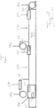
- the packaging machine shown comprises an elongated machine frame 35 which extends in a transport direction T in which the foils 11, 13, 15 used for the desired production of multi-layer packs are moved.
- the foils 11, 13, 15 are each in the form of a foil web which is fed from a supply roll 11a, 13a, 15a.
- a circulating endless transport chain (not shown) is provided in a basically known manner on both sides of the machine frame 35, which is guided on the machine frame 35 in a respective chain guide and holds the lower film 11 at an edge area.
- the lower film 11 is clamped in this way between the two transport chains spaced apart transversely to the transport direction T.
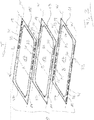
- the perforations 31 each include a plurality of gas passages 32, oval in this exemplary embodiment, which are formed in a front region of the respective film edge region 29, as seen in the transport direction T.
- the gas passages 32 can each be an opening produced by removing material, for example by punching.
- the passages 32 can each be formed without removing material, for example by cutting and then opening out a respective flap-like material section.
- the work station 21 can be saved and the length of the packaging machine can be reduced if a pre-perforated lower film 11 is used and, in addition, reshaping of the lower film is not required.
- a product to be packaged (not shown) is placed on the lower film 11.
- the product can, for example, be a portion of one or more product slices separated from a food product, for example sausage, ham or cheese, by means of a high-performance slicer.
- the transport path in which the lower film 11 is transported is fed from above a middle film 13, which has at least essentially the same web width B ( Fig. 2 ) as the lower film 11.
- the edge regions 19 of the central film 13 each have the same width as the corresponding edge region 19 of the lower film 11.
- the edge regions 19 of the central film 13 are unperforated, so that the perforations 31 of the lower film 11 each come from the corresponding edge region 19 of the Central film 13 are covered when the central film 13 lies on the lower film 11.
- the area between two superimposed product areas 17 of the lower film 11 and the upper film 13 contains the previously placed product and is also referred to as the product layer in the present disclosure. If - as shown - the lower film does not have any depressions produced by forming, these product layers are not chambers or compartments with a receiving volume determined by the forming, but rather only around areas between the lower film 11 and the upper film 13 in which a product is located.
- the lateral, front and rear boundaries of the product layers are each defined by a circumferential end seal 37, which will be discussed in more detail below.
- each film is often a composite of a plurality of individual film layers connected to one another, one on top of the other, which have different functions and therefore have different properties and / or can consist of different materials.
- each of these individual layers is not necessarily melted, but rather only one outer film layer, for example.
- a lower evacuation and / or gassing tool 41 which is explained in more detail below, is on the one hand a lower evacuation and / or gas supply tool 41 of a sealing station 29 explained in more detail below and the sealing tool 43 of the sealing station 25, on the other hand, arranged offset from one another in the transport direction T and each shorter than a pack length L ( Fig. 2 ).
- the length of each of these tools 43, 41 is only about half the length of a pack L. Consequently, the sealing station 25 only needs to be about half the length of a pack length L.
- the packaging machine does not require any additional means of transport and, in particular, no transport chains, as are provided for the lower film 11, since the sealing of the central film 13 to the lower film 11 explained above, both for reliable transport of the central film 13 and for always correct transport Alignment of the central film 13 relative to the lower film 11 ensures.
- the middle film 13 thus forms an upper product layer between the two product areas 17, which contains the previously placed upper product.
- FIG. 1 A work station 28 is arranged in the feed path of the upper film 15, in which a perforation 31 is made in each of the edge areas 19 of the upper film 15 ( Fig. 2 ).
- the perforations 31 of the upper film 15 can be identical in size, shape and position to the perforations 31 of the lower film 11. But this is not mandatory.
- the perforations 31 of the upper film 15 - in contrast to the lower film 11 - are each formed in a rear region of the respective edge region 19, as seen in the transport direction T.
- the perforations 31 of the upper film 15 are consequently, viewed in the transport direction T, arranged offset with respect to the perforations 31 of the lower film 11, the perforations 31 of the upper film 15 being located do not overlap with the perforations 31 of the lower film 11.
- the perforations 31 of the upper film 15 overlap with the seals 33 of the central film 13.
- all perforations 31 and seals 33 of the left edge areas 19, seen in transport direction T, and all perforations 31 and seals 33 of right edge areas 19, seen in transport direction T, are each located on a common working line W running parallel to transport direction T.
- the left working line W is indicated in all three foils 11, 13 and 15 by a dashed line, while the right working line W is indicated by a dash-dotted line.
- the lower product layer between the middle film 13 and the lower film 17 and the upper product layer between the middle film 13 and the upper film 15 are simultaneously subjected to a gas exchange by first evacuating the product layers and then applying a protective gas.
- a gas exchange by first evacuating the product layers and then applying a protective gas.
- the tools 41, 45 for evacuating and gassing the product layers are aligned with the respective gas outlets 32 of the lower film 11 and the upper film 15 in terms of their position transverse to the transport direction T and in relation to a respective pack P in the transport direction T.
- These tools 41, 45 can each be nozzles which are each aligned with one of the gas passages 32.
- the sealing station 29 comprises a sealing tool, not shown, which is designed in a basically known manner to connect all three foils 11, 13 and 15 to one another by forming an end seal 37 that runs around the product areas 17 of the foils and thereby the lower product layer and the to close the upper product layer in a gastight manner.
- the lateral areas of the end seal 37 lie within the edge areas 19 of the foils 11, 13, 15.
- the sections of the edge areas 19 lying outside the end seal 37 are separated downstream of the sealing station 29, optionally before or after the packs P are labeled.
- the seals 33 and the perforations 31 are no longer present on the final packs, as they will be commercially available for example later.
- the packaging machine according to the invention works in cycles. In each work cycle, the foils 11, 13 and 15 are moved together by one working length in the transport direction T, the working length of the packaging machine corresponding to the format length already mentioned at the beginning, i.e. at least one pack length L.
- the packaging machine can produce the packs P in one or more lanes.
- the upper film 11, the central film 13 and the upper film 15 can each be formed by a separate film web for each of the tracks running parallel next to one another in the transport direction T.
- all tracks can have a common lower film 11, a common central film 13 and also a have common upper film 15.
- the tools of the individual work stations are designed in such a way that between two adjacent tracks the edge regions 19 according to FIG Fig. 2 corresponding areas can be provided with the perforations 31 or seals 33.
- each unperforated middle foils can be fed in one after the other. This consequently results in at least one product layer that is delimited neither by the lower film 11 nor by the upper film 15, but rather by two unperforated central films.
- a certain gas exchange can also take place from the side between the foils lying on top of one another.
- this product layer can optionally be used for products for which a gas exchange is not absolutely necessary and generally dispensable, for example for small packaging of additives such as mustard or dry spices (e.g. salt and pepper), for napkins, cutlery and / or toothpicks or for product information, advertising flyers, raffle tickets, etc.
Landscapes
- Engineering & Computer Science (AREA)
- Mechanical Engineering (AREA)
- Chemical & Material Sciences (AREA)
- Dispersion Chemistry (AREA)
- Containers And Plastic Fillers For Packaging (AREA)
Description
Die Erfindung betrifft eine Verpackungsmaschine, insbesondere für Lebensmittelprodukte, mit mehreren längs einer Transportrichtung hintereinander angeordneten Arbeitsstationen zum Herstellen von Mehrlagenpackungen aus einer Unterfolie, einer Oberfolie und wenigstens einer dazwischen liegenden Mittelfolie, wobei die Unterfolie mit der Mittelfolie eine untere Produktlage und die Oberfolie mit der oder einer weiteren Mittelfolie eine obere Produktlage einer jeweiligen Packung einschließt, wobei die Folien jeweils einen Produktbereich und seitlich neben dem Produktbereich parallel zur Transportrichtung verlaufende Randbereiche aufweisen.The invention relates to a packaging machine, in particular for food products, with several workstations arranged one behind the other along a transport direction for the production of multi-layer packs from a lower film, an upper film and at least one intermediate film, the lower film with the central film being a lower product layer and the upper film with the or a further central film encloses an upper product layer of a respective pack, the films each having a product area and laterally adjacent to the product area edge areas running parallel to the transport direction.
Die Erfindung betrifft außerdem ein Verfahren zum Herstellen derartiger Mehrlagenpackungen.The invention also relates to a method for producing such multi-layer packs.
Außerdem betrifft die Erfindung Verwendungen bestimmter Folien in einer derartigen Verpackungsmaschine und/oder in einem derartigen Verfahren.The invention also relates to uses of certain films in such a packaging machine and / or in such a method.
Des Weiteren betrifft die Erfindung eine Mehrlagenpackung, die durch eine derartige Verpackungsmaschine hergestellt oder herstellbar ist und/oder die durch ein derartiges Verfahren erhalten oder erhältlich ist.The invention also relates to a multi-layer pack which is produced or can be produced by such a packaging machine and / or which is obtained or obtainable by such a method.
Die Herstellung von Mehrlagenpackungen beispielsweise zum Verpacken von Lebensmittelprodukten ist grundsätzlich bekannt. In Mehrlagenpackungen liegen wenigstens zwei Produkte übereinander, wobei jeweils zwei unmittelbar übereinander liegende Produktlagen durch eine Mittelfolie voneinander getrennt sind. Die Mittelfolien werden auch manchmal als Zwischenfolien oder - genauso wie die oberste Folie der Packung - als Oberfolien bezeichnet. In der vorliegenden Offenbarung werden alle zwischen der untersten Folie (der Unterfolie) und der obersten Folie (der Oberfolie) liegenden Folien jeweils als Mittelfolie bezeichnet.The production of multi-layer packs, for example for packaging food products, is known in principle. In multi-layer packs, at least two products lie on top of one another, with two product layers lying directly on top of one another being separated from one another by a central film. The middle foils are also sometimes called intermediate foils or - just like the top one Foil of the pack - referred to as top foils. In the present disclosure, all of the films located between the lowest film (the lower film) and the uppermost film (the upper film) are each referred to as the middle film.
In derartigen Packungen kommen Folienbahnen zum Einsatz, die jeweils eine Bahnbreite aufweisen, auf welche die Verpackungsmaschine abgestimmt sein muss. Die Randbereiche der Folien werden dazu verwendet, die Folien durch Siegeln miteinander zu verbinden. Außerdem können die Randbereiche der Folien mit Lochungen versehen werden, über welche die Produktlagen zugänglich sind, um die Produktlagen zu evakuieren und mit einem Schutzgas zu befüllen. Ein derartiger Gasaustausch ist in der Praxis häufig bevorzugt, grundsätzlich aber nicht zwingend. In manchen Anwendungen genügt es, die Produktlagen vor dem endgültigen Versiegeln lediglich zu evakuieren. Wenn ein Gasaustausch erwünscht ist, kann das Evakuieren und Begasen nacheinander zum Beispiel über die gleichen Lochungen erfolgen. Üblicherweise werden allerdings für das Evakuieren und das Begasen verschiedene Löcher verwendet. Allgemein ist es in der Praxis - insbesondere aus hygienischen Gründen - also bevorzugt, das Evakuieren und das Begasen auf unterschiedlichen Strömungswegen durchzuführen, Es ist z.B. möglich, die Produktlagen gleichzeitig über den einen gelochten Randbereich zu begasen und über den gegenüberliegenden Randbereich zu evakuieren. Ein aktives Evakuieren kann auch entfallen, wenn Schutzgas über den einen gelochten Randbereich eingeführt wird und über den gegenüberliegenden gelochten Randbereich austritt, die betreffende Produktlage also gewissermaßen mit dem Schutzgas gespült wird.In such packs, film webs are used, each of which has a web width to which the packaging machine must be adapted. The edge areas of the foils are used to connect the foils to one another by sealing. In addition, the edge areas of the foils can be provided with perforations through which the product layers are accessible in order to evacuate the product layers and to fill them with a protective gas. Such a gas exchange is often preferred in practice, but in principle not mandatory. In some applications it is sufficient to simply evacuate the product layers before the final sealing. If gas exchange is desired, evacuation and gassing can take place one after the other, for example through the same perforations. Usually, however, different holes are used for evacuation and gassing. In general, it is therefore preferred in practice - especially for hygienic reasons - to carry out evacuation and gassing on different flow paths.For example, it is possible to simultaneously gass the product layers via one perforated edge area and evacuate them via the opposite edge area. Active evacuation can also be dispensed with if protective gas is introduced through one perforated edge area and exits through the opposite perforated edge area, that is to say the product layer in question is flushed with the protective gas, so to speak.
Sowohl das Beaufschlagen mit Vakuum und/oder Gas als auch das endgültige Verschließen der Produktlagen erfolgt in der Praxis meist in einer einzigen Arbeitsstation, die als Siegelstation bezeichnet wird, da das Verschließen der Produktlagen und damit das endgültige Verschließen der Mehrlagenpackung durch Versiegeln erfolgt. Diese um die Produktbereiche umlaufende Endsiegelung, die in der Praxis auch als Siegelnaht bezeichnet wird, liegt innerhalb der Lochungen der Randbereiche, da die gelochten Abschnitte der Randbereiche anschließend - üblicherweise in einer sich an die Siegelstation anschließenden Arbeitsstation - abgetrennt werden. Davor oder danach werden die Packungen in der Praxis meist noch mit einem Etikett versehen.In practice, both the application of vacuum and / or gas and the final closing of the product layers usually take place in a single work station, which is referred to as the sealing station, since the closing of the product layers and thus the final closing of the multi-layer pack is carried out by sealing. This end seal surrounding the product areas, which is in the In practice, also referred to as a sealing seam, lies within the perforations of the edge areas, since the perforated sections of the edge areas are then separated - usually in a work station connected to the sealing station. Before or after this, the packs are usually provided with a label in practice.
Bei einer typischen Verpackungsmaschine der hier in Rede stehenden Art werden die die untere Produktlage bildenden Produkte auf den Produktbereich der Unterfolie gelegt, die der Maschine eingangsseitig zugeführt wird. Stromabwärts der Produktablagestelle wird die Mittelfolie zugeführt, wodurch die untere Produktlage eingeschlossen wird. In der Praxis wird häufig die Mittelfolie an der Unterfolie fixiert, um während des weiteren Transports in der Verpackungsmaschine eine korrekte Relativlage zwischen Mittelfolie und Unterfolie zu gewährleisten. Dieses Fixieren erfolgt meist durch sogenanntes Ansiegeln, bei dem die Mittelfolie und die Unterfolie durch Bilden von Siegelpunkten aneinander geheftet werden. Eine derartige Ansiegelung stellt noch keine gasdichte Endversiegelung dar, sondern dient - wie erwähnt - lediglich einer Fixierung der beiden Folien aneinander.In a typical packaging machine of the type in question here, the products forming the lower product layer are placed on the product area of the lower film that is fed to the machine on the input side. The central film is fed downstream of the product depositing point, thereby enclosing the lower product layer. In practice, the central film is often fixed to the lower film in order to ensure a correct relative position between the central film and the lower film during further transport in the packaging machine. This fixing is usually done by what is known as sealing, in which the middle film and the lower film are attached to one another by forming sealing points. Such a seal does not yet represent a gas-tight end seal, but rather serves - as mentioned - only to fix the two films to one another.
Anschließend werden die die obere Produktlage bildenden Produkte auf die Mittelfolie aufgelegt, und zwar an denjenigen Stellen, an denen zuvor die erste Produktlage aufgelegt wurde. Es können daraufhin noch weitere Produktlagen und Mittelfolien aufgebracht werden, um Mehrlagenpackungen mit mehr als zwei übereinander liegenden Produktlagen herzustellen.The products forming the upper product layer are then placed on the middle film, specifically at those points where the first product layer was previously placed. Further product layers and middle films can then be applied in order to produce multi-layer packs with more than two product layers lying one above the other.
Typischerweise werden derartige Verpackungsmaschinen taktweise betrieben. Dabei werden in jedem Takt die Folienbahnen jeweils um eine Arbeitslänge in Transportrichtung bewegt, wobei die Arbeitslänge der in Transportrichtung gemessenen Länge zumindest einer Packung entspricht. In der Praxis beträgt diese auch als Vorzug oder Formatlänge bezeichnete Arbeitslänge meistens das n-fache einer Packungslänge, gegebenenfalls zuzüglich Verschnitt jeweils zwischen zwei unmittelbar aufeinander folgenden Packungen, wobei n die Anzahl der in Transportrichtung aufeinander folgenden Packungen in einem jeweiligen Format ist.Typically, such packaging machines are operated cyclically. In each cycle, the film webs are moved by one working length in the transport direction, the working length corresponding to the length measured in the transport direction of at least one pack. In practice, this working length, also referred to as the preferred or format length, is usually n times the length of a pack, possibly plus scrap between two immediately consecutive packs, where n is the number of packs following one another in the transport direction in a respective format.
Nach dem Aufbringen der einzigen oberen Produktlage oder der letzten von mehreren oberen Produktlagen wird die Oberfolie zugeführt, sodass auch die obere bzw. oberste Produktlage eingeschlossen wird. Die wenigstens drei Folienbahnen mit den eingeschlossenen Produktlagen gelangen anschließend in die bereits erwähnte Siegelstation, in welcher die Produktlagen durch die in den Randbereichen der Folien vorhandenen Lochungen hindurch mit Vakuum und/oder Gas beaufschlagt und endgültig versiegelt werden.After the single top product layer or the last of several top product layers have been applied, the top film is fed in so that the top or top product layer is also enclosed. The at least three film webs with the enclosed product layers then reach the sealing station already mentioned, in which the product layers are subjected to vacuum and / or gas through the perforations in the edge areas of the films and are finally sealed.
In Abhängigkeit von dem jeweiligen Arbeitsprinzip der Verpackungsmaschine sind für die einzelnen Arbeitsschritte entsprechende Arbeitsstationen erforderlich, die in Transportrichtung hintereinander angeordnet werden müssen. Bereits dann, wenn die herzustellende Packung lediglich zwei Produktlagen und somit lediglich eine einzige Mittelfolie aufweist, können die erforderlichen Arbeitsschritte zu einem relativ komplexen Aufbau der Verpackungsmaschine und insbesondere zu einer vergleichsweise großen Maschinenlänge führen. Dies erhöht die Kosten und erfordert vergleichsweise viel Platz beim Betreiber der Verpackungsmaschine.Depending on the respective working principle of the packaging machine, corresponding work stations are required for the individual work steps, which must be arranged one behind the other in the transport direction. Even when the pack to be produced has only two product layers and thus only a single central film, the necessary work steps can lead to a relatively complex structure of the packaging machine and, in particular, to a comparatively long machine length. This increases the costs and requires a comparatively large amount of space for the operator of the packaging machine.
Hierbei ist auch zu berücksichtigen, dass häufig zumindest die Unterfolie umgeformt werden muss, um schalenartige Verpackungsunterteile zu bilden. Hierzu muss die Unterfolie eine sogenannte Tiefziehstation der Verpackungsmaschine durchlaufen. In manchen Anwendungen ist es gewünscht, auch die Mittelfolie umzuformen. Dies erhöht die Komplexität und die Länge der Verarbeitungsmaschine weiter. Der Aufwand vergrößert sich noch weiter, wenn die Verpackungsmaschine dazu in der Lage sein muss, auch die oder jede Mittelfolie zu lochen, um den erforderlichen Zugang zu einer betreffenden Produktlage zum Evakuieren und/oder Begasen zu gewährleisten.It should also be taken into account here that at least the lower film often has to be reshaped in order to form shell-like lower packaging parts. To do this, the lower film must pass through a so-called deep-drawing station on the packaging machine. In some applications it is desirable to reshape the central film as well. This further increases the complexity and length of the processing machine. The effort increases even further if the packaging machine must also be able to perforate the or each central film in order to ensure the necessary access to a relevant product layer for evacuation and / or gassing.
Bei einer aus
Bei einer in
Auch bei der aus
Aufgabe der Erfindung ist es, eine Möglichkeit zu schaffen, Mehrlagenpackungen so einfach wie möglich herzustellen, wobei insbesondere die hierfür verwendete Verpackungsmaschine einen möglichst einfachen Aufbau und insbesondere eine möglichst geringe Maschinenlänge aufweisen soll.The object of the invention is to create a possibility of producing multi-layer packs as simply as possible, with the packaging machine used for this purpose in particular having the simplest possible structure and in particular the shortest possible machine length.
Die Lösung dieser Aufgabe erfolgt jeweils durch die Merkmale der unabhängigen Ansprüche.This object is achieved in each case by the features of the independent claims.
Bei der erfindungsgemäßen Verpackungsmaschine ist eine Arbeitsstation eine Siegelstation, die dazu ausgebildet ist, die Produktlagen durch in den Randbereichen der Oberfolie und der Unterfolie vorhandene Lochungen hindurch mit Vakuum und/oder Gas zu beaufschlagen und dann durch Versiegeln der Folien zu verschließen, wobei die Siegelstation ein mit der Lochung der Oberfolie ausgerichtetes oberes Evakuierungs- und/oder Begasungswerkzeug und ein mit der Lochung der Unterfolie ausgerichtetes unteres Evakuierungs- und/oder Begasungswerkzeug umfasst, wobei eine weitere Arbeitsstation eine stromaufwärts der Siegelstation gelegene Ansiegelstation ist, die dazu ausgebildet ist, die Mittelfolie an die Unterfolie an einer in den Randbereichen gelegenen Ansiegelung anzusiegeln, und wobei das untere Evakuierungs- und/oder Begasungswerkzeug der Siegelstation und ein zur Herstellung der Ansiegelung dienendes Ansiegelwerkzeug der Ansiegelstation auf einen gemeinsamen, parallel zur Transportrichtung verlaufenden Arbeitslinie liegen.In the packaging machine according to the invention, a work station is a sealing station which is designed to apply vacuum and / or gas to the product layers through perforations in the edge areas of the upper film and the lower film and then to close them by sealing the films, the sealing station being a comprises the upper evacuation and / or gassing tool aligned with the perforation of the upper film and a lower evacuation and / or gassing tool aligned with the perforation of the lower film, a further work station being a sealing station located upstream of the sealing station, which is designed to attach the central film to seal the lower film to a seal located in the edge areas, and wherein the lower evacuation and / or gassing tool of the sealing station and a sealing tool of the sealing station serving to produce the seal on a common, parallel to the transport direction ve running working line.
Dass das untere Evakuierungs- und/oder Begasungswerkzeug und das Ansiegelwerkzeug auf einer Arbeitslinie liegen, bedeutet, dass die Verpackungsmaschine dazu ausgebildet ist, während des Betriebs auf überlappenden Randbereichen von in Transportrichtung transportierten Folien eine Ansiegelung herzustellen und mit einer Lochung zusammenzuwirken, wobei die Ansiegelung und die Lochung auf der gleichen Querposition, d.h. auf einer gemeinsamen, parallel zur Transportrichtung verlaufenden Linie oder innerhalb eines parallel zur Transportrichtung verlaufenden Streifens liegen, dessen Breite nicht größer als die Breite der Randbereiche ist.The fact that the lower evacuation and / or gassing tool and the sealing tool are on a working line means that the packaging machine is designed to produce a seal during operation on overlapping edge areas of foils transported in the transport direction and to interact with a perforation, the sealing and the perforation in the same transverse position, ie on a common, parallel to the transport direction running line or within a strip running parallel to the transport direction, the width of which is not greater than the width of the edge areas.
Diese Ausgestaltung der erfindungsgemäßen Verpackungsmaschine schließt eine gemeinsame oder unabhängige Verstellbarkeit der Werkzeuge quer zur Transportrichtung auch für andere Anwendungen nicht aus.This embodiment of the packaging machine according to the invention does not rule out a common or independent adjustability of the tools transversely to the transport direction, even for other applications.
Bei dem erfindungsgemäßen Verfahren werden die Produktlagen durch in den Randbereichen der Oberfolie und der Unterfolie vorhandene Lochungen hindurch mit Vakuum und/oder Gas beaufschlagt und dann durch Versiegeln der Folien verschlossen, wobei das Beaufschlagen mit Vakuum und/oder Gas erfolgt, während der ungelochte Randbereich der Mittelfolie und die gelochten Randbereiche der Unterfolie und der Oberfolie einander überlappen, und wobei die untere Produktlage durch die Lochung der Unterfolie und die obere Produktlage durch die Lochung der Oberfolie hindurch beaufschlagt wird.In the method according to the invention, vacuum and / or gas are applied to the product layers through perforations in the edge areas of the upper film and the lower film and then closed by sealing the films, the application of vacuum and / or gas taking place, while the unperforated edge region of the The middle film and the perforated edge areas of the lower film and the upper film overlap one another, and the lower product layer is acted upon by the perforation of the lower film and the upper product layer is acted upon through the perforation of the upper film.
Erfindungsgemäß wurde erkannt, dass der Randbereich der Mittelfolie die Randbereiche der Unterfolie und der Oberfolie überlappen kann und dabei nicht gelocht zu sein braucht, wenn die Siegelstation der Verpackungsmaschine dazu ausgebildet ist, die obere Produktlage durch die Oberfolie hindurch und die untere Produktlage durch die Unterfolie hindurch zu beaufschlagen. Eine Arbeitsstation zum Lochen der Mittelfolie kann folglich eingespart werden. Die Verpackungsmaschine kann deshalb um zumindest eine Arbeitslänge und damit Taktlänge verkürzt werden. Eine weitere Vereinfachung der Verpackungsmaschine ergibt sich dadurch, dass an den Lochungen der Unterfolie und der Oberfolie keine Umsiegelungen gebildet werden müssen, da die Lochung der Unterfolie nur Zugang zur unteren Produktlage und die Lochung der Oberfolie nur Zugang zur oberen Produktlage verschaffen muss.According to the invention, it was recognized that the edge area of the middle film can overlap the edge areas of the lower film and the upper film and does not need to be perforated if the sealing station of the packaging machine is designed to pass the upper product layer through the upper film and the lower product layer through the lower film to apply. A work station for perforating the central film can therefore be saved. The packaging machine can therefore be shortened by at least one working length and thus cycle length. A further simplification of the packaging machine results from the fact that no seals have to be formed on the perforations of the lower film and the upper film, since the perforation of the lower film only has to provide access to the lower product layer and the perforation of the upper film only has to provide access to the upper product layer.
Die Fähigkeit der erfindungsgemäßen Siegelstation, die übereinanderliegenden Folien sowohl von unten als auch von oben zur Evakuierung und/oder Begasung zu beaufschlagen, erhöht den Aufwand für Konstruktion und Betrieb der Siegelstation und der Verpackungsmaschine insgesamt allerdings nur scheinbar. Denn das untere Werkzeug und das obere Werkzeug können jeweils einfacher aufgebaut sein und betrieben werden als bei einer Siegelstation, die mehrere übereinander liegende Produktlagen von einer einzigen Seite aus beaufschlagen können muss. Zudem braucht die erfindungsgemäße Siegelstation keine aufwendigen Zusatzmaßnahmen wie Einrichtungen zur Herstellung von Lochumsiegelungen aufzuweisen, die dann erforderlich sind, wenn von einer einzigen Seite aus ein direkter Zugang zu den einzelnen Produktlagen erforderlich ist.The ability of the sealing station according to the invention to act on the superimposed foils both from below and from above for evacuation and / or gassing increases the expenditure for the construction and operation of the sealing station and the packaging machine overall, however, only apparently. This is because the lower tool and the upper tool can each be constructed and operated more simply than with a sealing station, which has to be able to act on several product layers lying one above the other from a single side. In addition, the sealing station according to the invention does not have to have any complex additional measures such as devices for producing hole seals, which are required when direct access to the individual product layers is required from a single side.
Das Überlappen der Randbereiche von Unterfolie und Oberfolie durch die ungelochten Randbereiche der Mittelfolie hat zudem den weiteren Vorteil, dass die Mittelfolie einfach durch Ansiegeln an die Unterfolie fixiert und so eine korrekte Ausrichtung von Mittelfolie und Unterfolie relativ zueinander gewährleistet werden kann. Hierdurch ist es möglich, den Randbereich der Unterfolie sowohl zum Evakuieren und/oder Begasen der unteren Produktlage als auch zum Ansiegeln der Mittelfolie an die Unterfolie zu nutzen.The overlapping of the edge areas of the lower film and the upper film by the unperforated edge regions of the central film also has the further advantage that the central film is simply fixed to the lower film by sealing, thus ensuring correct alignment of the central film and the lower film relative to one another. This makes it possible to use the edge area of the lower film both for evacuating and / or gassing the lower product layer and for sealing the middle film to the lower film.
Dabei brauchen die Randbereiche nur so breit zu sein, wie es entweder für die Lochung oder die Ansiegelung erforderlich ist, wenn gemäß der erfindungsgemäßen Verpackungsmaschine das untere Evakuierungs- und/oder Begasungswerkzeug der Siegelstation und das Ansiegelwerkzeug der Ansiegelstation quer zur Transportrichtung miteinander ausgerichtet sind, d.h. auf einer gemeinsamen, parallel zur Transportrichtung verlaufenden Arbeitslinie liegen. Es wurde erkannt, dass die Lochung der Unterfolie und die Ansiegelung derart gebildet werden können, dass weder der Evakuierungs- und/oder Begasungsvorgang, noch das Herstellen der Ansiegelung oder die Fixierungsfunktion der Ansiegelung beeinträchtigt werden.The edge areas only need to be as wide as is necessary either for the perforation or the sealing if, according to the packaging machine according to the invention, the lower evacuation and / or gassing tool of the sealing station and the sealing tool of the sealing station are aligned with each other transversely to the transport direction, ie lie on a common working line running parallel to the transport direction. It has been recognized that the perforation of the lower film and the seal can be formed in such a way that neither the evacuation and / or gassing process, nor the production of the seal or the fixing function of the seal are impaired.
Dies bedeutet außerdem, dass die Mittelfolie weder breiter noch schmaler sein muss als die Unterfolie. Vielmehr ergibt sich durch die Erfindung der Vorteil, dass nicht nur die Mittelfolie und die Unterfolie, sondern alle Folienbahnen zumindes im Wesentlichen die gleiche Bahnbreite aufweisen können. Für den Betreiber der Verpackungsmaschine vereinfachen sich hierdurch Beschaffung und Lagerhaltung der einzelnen Folien erheblich.This also means that the middle film does not have to be wider or narrower than the lower film. Rather, the invention results in the advantage that not only the middle film and the lower film, but all film webs at least can have essentially the same web width. This considerably simplifies the procurement and storage of the individual films for the operator of the packaging machine.
Die Erfindung betrifft folglich außerdem die Verwendung einer ungelochten Folie als Mittelfolie in einer Verpackungsmaschine der hierin offenbarten Art und/oder in einem Verfahren der hierin offenbarten Art.The invention consequently also relates to the use of a non-perforated film as a central film in a packaging machine of the type disclosed herein and / or in a method of the type disclosed herein.
Des Weiteren betrifft die Erfindung außerdem eine Verwendung wenigstens dreier Folien zumindest im Wesentlichen gleicher Bahnbreite als Unterfolie, Oberfolie und Mittelfolie in einer Verpackungsmaschine der hierin offenbarten Art und/oder in einem Verfahren der hierin offenbarten Art.Furthermore, the invention also relates to the use of at least three films of at least essentially the same web width as the lower film, upper film and middle film in a packaging machine of the type disclosed herein and / or in a method of the type disclosed herein.
Generell sind hierin unter "zumindest im Wesentlichen gleicher Bahnbreite" auch geringfügige Abweichungen z.B. aufgrund nicht zu vermeidender Herstellungstoleranzen zu verstehen, die in der Praxis bis zu 2mm und manchmal auch bis zu 5mm betragen können, und zwar bei einer Nennbahnbreite von typischerweise mehreren 100mm.In general, "at least essentially the same web width" also includes slight deviations, e.g. due to unavoidable manufacturing tolerances, which in practice can be up to 2mm and sometimes up to 5mm, with a nominal web width of typically several 100mm.
Vorteilhafte Ausführungsformen sowohl der erfindungsgemäßen Verpackungsmaschine als auch des erfindungsgemäßen Herstellungsverfahrens sind auch in den abhängigen Ansprüchen, der nachfolgenden Beschreibung sowie den Figuren angegeben.Advantageous embodiments of both the packaging machine according to the invention and the production method according to the invention are also specified in the dependent claims, the following description and the figures.
Bevorzugt ist vorgesehen, dass bezogen auf eine jeweilige Packung das untere Evakuierungs- und/oder Begasungswerkzeug und das Ansiegelwerkzeug in Transportrichtung einander nicht überlappen. Beide Werkzeuge können folglich vergleichsweise kurz, nämlich kürzer als eine Packungslänge, ausgebildet sein. Dies ermöglicht eine weitere Reduzierung der Länge der Verpackungsmaschine.It is preferably provided that, based on a respective pack, the lower evacuation and / or gassing tool and the sealing tool in Do not overlap the transport directions. Both tools can consequently be made comparatively short, namely shorter than a package length. This enables a further reduction in the length of the packaging machine.
Eine solche Anordnung der Werkzeuge ist allerdings nicht zwingend. Die Werkzeuge können auch derart in Transportrichtung relativ zueinander angeordnet sein, dass bezogen auf eine jeweilige Packung ein Ansiegelbereich und ein Lochungsbereich in Transportrichtung einander überlappen. Der Ansiegelbereich und der Lochungsbereich können sich dabei jeweils über die gesamte Packungslänge oder zumindest über einen wesentlichen Teil der Packungslänge erstrecken. Damit die Lochung und die Ansiegelung einander nicht beeinträchtigen, kann beispielsweise vorgesehen sein, dass in Transportrichtung abwechselnd jeweils ein Gasdurchlass der Lochung und eine Ansiegelstelle der Ansiegelung aufeinanderfolgen. Hierdurch können zumindest im Wesentlichen die gesamte Packungslänge und somit die gesamten, zudem vergleichsweise schmal ausführbaren Randbereiche von Unterfolie und Mittelfolie sowohl für die Lochung als auch für die Ansiegelung genutzt werden.However, such an arrangement of the tools is not mandatory. The tools can also be arranged relative to one another in the transport direction in such a way that, with respect to a respective pack, a sealing area and a perforation area overlap in the transport direction. The sealing area and the perforation area can each extend over the entire length of the pack or at least over a substantial part of the length of the pack. So that the perforation and the seal do not affect one another, it can be provided, for example, that a gas passage of the perforation and a sealing point of the seal alternate in the transport direction. As a result, at least essentially the entire length of the pack and thus the entire edge regions of the lower film and the middle film, which can also be made comparatively narrow, can be used both for the perforation and for the sealing.
Bevorzugt ist die Verpackungsmaschine taktweise betreibbar, wobei in einem jeweiligen Takt die Folien um eine zumindest einer Packungslänge entsprechende Arbeitslänge in Transportrichtung bewegbar sind.The packaging machine can preferably be operated cyclically, the foils being movable in the transport direction by a working length corresponding to at least one pack length in a respective cycle.
Wenn nicht die gesamte Packungslänge sowohl für das Beaufschlagen mit Vakuum und/oder Gas als auch für das Ansiegeln genutzt werden soll, dann kann vorgesehen sein, dass bezogen auf eine jeweilige Packung das untere und/oder obere Evakuierungs- und/oder Begasungswerkzeug einerseits und das Ansiegelwerkzeug andererseits jeweils eine Länge in Transportrichtung aufweisen, deren Summe kleiner als die Arbeitslänge ist. In der Praxis sind häufig die Funktionen der Siegelstation, nämlich das Evakuieren und/oder Begasen einerseits und das endgültige Verschließen durch Versiegeln andererseits in einem einzigen gemeinsamen Werkzeug vereinigt, d.h. man spricht in diesem Fall nicht von unterschiedlichen Werkzeugen. In diesem Fall ist unter diesem Ausführungsbeispiel zu verstehen, dass an dem gemeinsamen Werkzeug ein Evakuierungs- und/oder Begasungsbereich vorgesehen ist, der sich nicht über die gesamte Arbeitslänge des Werkzeugs erstreckt.If the entire length of the pack is not to be used both for applying a vacuum and / or gas and for sealing, then it can be provided that, based on a respective pack, the lower and / or upper evacuation and / or gas injection tool on the one hand and the Sealing tools on the other hand each have a length in the transport direction, the sum of which is smaller than the working length. In practice, the functions of the sealing station, namely evacuation and / or gassing on the one hand and the final closing by sealing on the other hand, are often in a single joint Tool unites, ie one does not speak of different tools in this case. In this case, this exemplary embodiment is to be understood as meaning that an evacuation and / or gassing area is provided on the common tool which does not extend over the entire working length of the tool.
Des Weiteren kann erfindungsgemäß vorgesehen sein, dass auch das obere Evakuierungs- und/oder Begasungswerkzeug auf der gemeinsamen Arbeitslinie liegt. Der Aufbau der Siegelstation kann hierdurch weiter vereinfacht werden.Furthermore, it can be provided according to the invention that the upper evacuation and / or gassing tool also lies on the common working line. The construction of the sealing station can hereby be further simplified.
Gemäß einem weiteren Ausführungsbeispiel ist vorgesehen, dass bezogen auf eine jeweilige Packung das obere Evakuierungs- und/oder Begasungswerkzeug und das Ansiegelwerkzeug in Transportrichtung einander überlappen. Die Trennung von unterer Packungslage und oberer Packungslage hinsichtlich des Beaufschlagens mit Vakuum und/oder Gas ermöglicht es folglich, die Position des oberen Evakuierungs- und/oder Begasungswerkzeugs hinsichtlich des Ansiegelwerkzeugs zum Ansiegeln der Mittelfolie an die Unterfolie in Transportrichtung variabel zu wählen. Denn die Ansiegelung zwischen Mittelfolie und Unterfolie einerseits und die Lochung der Oberfolie andererseits beeinflussen einander nicht.According to a further exemplary embodiment, it is provided that the upper evacuation and / or gassing tool and the sealing tool overlap one another in the transport direction, with reference to a respective pack. The separation of the lower package layer and the upper package layer with regard to the application of vacuum and / or gas consequently makes it possible to select the position of the upper evacuation and / or gas injection tool with regard to the sealing tool for sealing the middle film to the lower film in the transport direction. Because the sealing between the middle film and the lower film on the one hand and the perforation of the upper film on the other hand do not influence each other.
Gemäß einer bevorzugten Ausgestaltung ist vorgesehen, dass das untere Evakuierungs- und/oder Begasungswerkzeug einerseits und das Evakuierungs- und/oder Begasungswerkzeug andererseits in Transportrichtung einander nicht überlappen. Eine derartige in Transportrichtung versetzte Anordnung der Werkzeuge kann für bestimmte Anwendungen und/oder im Hinblick auf einen einfacheren Aufbau und/oder Betrieb der Siegelstation und damit der Verpackungsmaschine von Vorteil sein.According to a preferred embodiment, it is provided that the lower evacuation and / or gassing tool on the one hand and the evacuation and / or gassing tool on the other hand do not overlap in the transport direction. Such an arrangement of the tools offset in the transport direction can be advantageous for certain applications and / or with regard to a simpler construction and / or operation of the sealing station and thus the packaging machine.
Eine Randbereiche der Unterfolie und der Oberfolie überlappende Mittelfolie ist insbesondere dann von Vorteil, wenn die Produktlagen nicht in geformten Vertiefungen liegen sollen oder müssen, sondern wenn es ausreichend oder gewünscht ist, die Produkte jeweils zwischen zwei ungeformten Folienbahnen zu verpacken. Daher kann gemäß einer bevorzugten Ausführungsform vorgesehen sein, dass die Verpackungsmaschine keine Tiefzieh- oder Formstation zur Herstellung von Umformungen in einer oder mehreren der Folien aufweist. Die Verpackungsmaschine kann hierdurch weiter vereinfacht und verkürzt werden.A middle film that overlaps the edge areas of the lower film and the upper film is particularly advantageous when the product layers are not in shaped depressions should or must lie, but when it is sufficient or desired to pack the products between two unformed film webs. Therefore, according to a preferred embodiment, it can be provided that the packaging machine does not have a deep-drawing or forming station for producing deformations in one or more of the foils. The packaging machine can be further simplified and shortened as a result.
Bei dem erfindungsgemäßen Verfahren kann vorgesehen sein, dass die untere Produktlage und die obere Produktlage gleichzeitig mit Vakuum und/oder Gas beaufschlagt werden.In the method according to the invention, it can be provided that the lower product layer and the upper product layer are simultaneously subjected to vacuum and / or gas.
Vorzugsweise erfolgt das Beaufschlagen mit Vakuum und/oder Gas einerseits und das Verschließen andererseits in einer eine der Arbeitsstationen bildenden Siegelstation.The application of vacuum and / or gas on the one hand and the closing on the other hand preferably takes place in a sealing station forming one of the work stations.
Vorzugsweise wird nach dem Zuführen der Unterfolie und der Mittelfolie der Randbereich der Mittelfolie an den Randbereich der Unterfolie angesiegelt. Ein Fixieren von Unterfolie und Mittelfolie aneinander kann grundsätzlich auch auf andere Art und Weise erfolgen.Preferably, after the lower film and the central film have been fed in, the edge region of the central film is sealed to the edge region of the lower film. A fixing of the lower film and the middle film to one another can in principle also take place in a different manner.
Des Weiteren ist bevorzugt vorgesehen, dass das Ansiegeln entlang einer parallel zur Transportrichtung verlaufenden Arbeitslinie erfolgt, auf der zumindest die Lochung der Unterfolie, bevorzugt auch die Lochung der Oberfolie, liegt.Furthermore, it is preferably provided that the sealing takes place along a working line running parallel to the transport direction, on which at least the perforation of the lower film, preferably also the perforation of the upper film, lies.
Es kann vorgesehen sein, dass in einer jeweiligen Packung das Ansiegeln in einem Ansiegelbereich erfolgt, der mit einem Lochungsbereich der Unterfolie in Transportrichtung nicht überlappt.It can be provided that in a respective pack the sealing takes place in a sealing area which does not overlap with a perforation area of the lower film in the transport direction.
Gemäß einem weiteren Ausführungsbeispiel werden die Unterfolie und die Oberfolie nicht gleichzeitig und/oder an unterschiedlichen, insbesondere in Transportrichtung voneinander beabstandeten, Orten der Verpackungsmaschine gelocht. Der Aufbau der Verpackungsmaschine kann hierdurch flexibler gestaltet werden.According to a further embodiment, the lower film and the upper film are not simultaneously and / or on different ones, in particular in the transport direction spaced apart locations of the packaging machine. The construction of the packaging machine can hereby be designed more flexibly.
Vorzugsweise werden die Unterfolie und/oder die Oberfolie beim Zuführen gelocht. Hierdurch ist es nicht notwendig, eine das Lochen durchführende Arbeitsstation innerhalb des Maschinenrahmens der Verpackungsmaschine anzuordnen. Vielmehr ist es möglich, ein Werkzeug zum Lochen der jeweiligen Folie außerhalb des Maschinenrahmens und insbesondere im Zuführweg der Folie anzuordnen. Ein ohnehin zum Zuführen der jeweiligen Folie zur Verfügung zu stellender Raum kann so gleichzeitig zum Lochen der Folie genutzt werden.The lower film and / or the upper film are preferably perforated during feeding. As a result, it is not necessary to arrange a work station performing the punching within the machine frame of the packaging machine. Rather, it is possible to arrange a tool for perforating the respective film outside the machine frame and in particular in the feed path of the film. A space that is to be made available anyway for feeding the respective film can thus be used at the same time for perforating the film.
Das Lochen der Unterfolie sowie das Lochen der Oberfolie müssen nicht zwingend in den Betrieb der Verpackungsmaschine integriert werden. Vielmehr ist es erfindungsgemäß auch möglich, eine vorgelochte Unterfolie und/oder eine vorgelochte Oberfolie zu verwenden, also Folien, die bereits bei ihrer Herstellung gelocht werden und im bereits gelochten Zustand vom Betreiber der Verpackungsmaschine eingesetzt werden.The perforation of the lower film and the perforation of the upper film do not necessarily have to be integrated into the operation of the packaging machine. Rather, according to the invention, it is also possible to use a pre-perforated lower film and / or a pre-perforated upper film, i.e. films which are already perforated during their production and are used by the operator of the packaging machine in the already perforated state.
Es kann vorgesehen sein, dass die Unterfolie und die Oberfolie derart gelocht oder entsprechend vorgelochte Folien verwendet werden, dass in einer jeweiligen Packung die Lochungen der Unterfolie und der Oberfolie in Transportrichtung einander nicht überlappen.It can be provided that the lower film and the upper film are perforated or correspondingly pre-perforated films are used in such a way that the perforations of the lower film and the upper film do not overlap in the transport direction in a respective pack.
Des Weiteren ist bevorzugt vorgesehen, dass die Lochungen jeweils einen oder mehrere Gasdurchlässe aufweisen, die jeweils entweder durch Materialwegnahme entstanden sind oder die ohne Materialwegnahme durch Einschneiden, Schlitzen oder Perforieren des Materials entstanden sind, bevorzugt zusätzlich durch Ausstellen eines oder mehrerer Materialabschnitte.Furthermore, it is preferably provided that the perforations each have one or more gas passages, each of which was created either by removing material or by cutting, slitting or perforating the material without removing material, preferably additionally by exposing one or more material sections.
Insbesondere dann, wenn die Lochungen während des Betriebs der Verpackungsmaschine erzeugt werden, hat die Bildung der Gasdurchlässe ohne Materialwegnahme den Vorteil, dass keine störenden Materialschnipsel entstehen.Particularly when the perforations are produced during the operation of the packaging machine, the formation of the gas passages without removing material has the advantage that no disruptive material snippets arise.
Bevorzugt ist vorgesehen, dass die Unterfolie, die Oberfolie und die Mittelfolie jeweils die gleiche Bahnweite aufweisen.It is preferably provided that the lower film, the upper film and the central film each have the same web width.
Wie bereits vorstehend anhand eines bevorzugten Ausführungsbeispiels der Verpackungsmaschine erwähnt, kann erfindungsgemäß vorgesehen sein, dass an keiner der Folien ein Tiefzieh- oder Formgebungsvorgang zur Herstellung von Umformungen durchgeführt werden kann.As already mentioned above with reference to a preferred exemplary embodiment of the packaging machine, it can be provided according to the invention that a deep-drawing or shaping process for the production of reshapes cannot be carried out on any of the foils.
Des Weiteren ist bevorzugt vorgesehen, dass das Beaufschlagen mit Vakuum und/oder Gas und das Ansiegeln jeweils auf beiden Seiten des Produktbereiches erfolgt, insbesondere gleichzeitig und/oder auf gleiche Weise.Furthermore, it is preferably provided that the application of vacuum and / or gas and the sealing take place on both sides of the product area, in particular simultaneously and / or in the same way.
Die Verpackungsmaschine kann hierbei bezüglich einer parallel zur Transportrichtung verlaufenden Mittelachse der Folien und somit der Maschine symmetrisch aufgebaut sein und/oder betrieben werden.The packaging machine can be constructed and / or operated symmetrically with respect to a central axis of the foils running parallel to the transport direction and thus the machine.
Die Erfindung wird im Folgenden beispielhaft unter Bezugnahme auf die Zeichnung beschrieben. Es zeigen:
- Fig. 1
- schematisch ein mögliches Ausführungsbeispiel einer erfindungsgemäßen Verpackungsmaschine in einer Seitenansicht, und
- Fig. 2
- den Aufbau einer erfindungsgemäßen Mehrlagenpackung aus drei Folien, die jeweils mit noch nicht abgetrennten Randbereichen und der besseren Übersichtlichkeit halber mit Abstand voneinander dargestellt sind.
- Fig. 1
- schematically a possible embodiment of a packaging machine according to the invention in a side view, and
- Fig. 2
- the structure of a multi-layer pack according to the invention from three films, each with not yet separated Edge areas and for the sake of clarity are shown at a distance from one another.
Die in
Für die Unterfolie 11 ist in grundsätzlich bekannter Weise an beiden Seiten des Maschinenrahmens 35 jeweils eine umlaufende Endlos-Transportkette (nicht dargestellt) vorgesehen, die am Maschinenrahmen 35 in einer jeweiligen Kettenführung geführt ist und die Unterfolie 11 jeweils an einem Randbereich festhält. Die Unterfolie 11 ist auf diese Weise zwischen den beiden quer zur Transportrichtung T beabstandeten Transportketten eingespannt.For the
Wenn keine vorgelochte Unterfolie 11 verwendet wird, dann schließt sich an die Zuführung der Unterfolie 11 eine Arbeitsstation 21 an, in welcher die Randbereiche der Unterfolie 11 jeweils mit einer Lochung 31 (
Des Weiteren ist es möglich, an der Arbeitsstation 21 eine Umformung der Unterfolie 11, insbesondere mittels eines Tiefziehvorgangs, durchzuführen, wenn die herzustellenden Packungen jeweils ein schalenförmiges Unterteil aufweisen sollen.Furthermore, it is possible to reshape the
Wie auch im Einleitungsteil erwähnt, kann die Arbeitsstation 21 eingespart und dadurch die Länge der Verpackungsmaschine reduziert werden, wenn eine vorgelochte Unterfolie 11 verwendet und außerdem eine Umformung der Unterfolie nicht benötigt wird.As also mentioned in the introductory part, the
Anschließend wird an einer lediglich durch einen Pfeil angedeuteten ersten Produktauflagestation 23 auf die einzelnen Produktbereiche 17 (
Anschließend wird der Transportstrecke, in welcher die Unterfolie 11 transportiert wird, von oben eine Mittelfolie 13 zugeführt, welche zumindest im Wesentlichen die gleiche Bahnbreite B (
Der Bereich zwischen jeweils zwei übereinander liegenden Produktbereichen 17 der Unterfolie 11 und der Oberfolie 13 enthält das jeweils zuvor aufgelegte Produkt und wird in der vorliegenden Offenbarung auch als Produktlage bezeichnet. Wenn - wie dargestellt - die Unterfolie keine durch Umformen hergestellte Vertiefungen aufweist, dann handelt es sich bei diesen Produktlagen nicht um Kammern oder Fächer mit einem durch die Umformung bestimmten Aufnahmevolumen, sondern lediglich um zwischen der Unterfolie 11 und der Oberfolie 13 vorhandene Bereiche, in denen sich ein Produkt befindet. Die seitlichen, vorderen und hinteren Begrenzungen der Produktlagen sind jeweils durch eine umlaufende Endsiegelung 37 definiert, auf die nachstehend näher eingegangen wird.The area between two
Nach dem Zuführen der Mittelfolie 13 wird diese an der Unterfolie 11 fixiert. Dies erfolgt durch Ansiegeln in einer Ansiegelstation 25, in der ein, in Transportrichtung T gesehen, hinterer Bereich jedes Randbereiches 19 der Mittelfolie 13 an einen entsprechenden Bereich der Unterfolie 11 angesiegelt wird.After the
Das Ansiegeln sowie das endgültige Versiegeln erfolgt jeweils in grundsätzlich bekannter Weise durch auf ausreichend hohe Temperaturen geheizte Siegelwerkzeuge, welche die beteiligten Folien lokal zum Schmelzen bringen und folglich miteinander verschmelzen. In der Praxis ist jede Folie häufig ein Verbund aus einer Mehrzahl von miteinander verbundenen, übereinander liegenden Einzelfolienlagen, die verschiedene Funktionen haben und deshalb unterschiedliche Eigenschaften aufweisen und/oder aus unterschiedlichen Materialien bestehen können. In einem Siegelprozess wird nicht notwendigerweise jede dieser Einzellagen aufgeschmolzen, sondern zum Beispiel jeweils nur eine äußere Folienlage.The sealing and the final sealing are each carried out in a basically known manner by means of sealing tools heated to sufficiently high temperatures, which locally melt the foils involved and consequently fuse them together. In practice, each film is often a composite of a plurality of individual film layers connected to one another, one on top of the other, which have different functions and therefore have different properties and / or can consist of different materials. In a sealing process, each of these individual layers is not necessarily melted, but rather only one outer film layer, for example.
Die mittels eines Ansiegelwerkzeugs 43 der Ansiegelstation 25 gebildeten Ansiegelungen 33 überlappen die Lochungen 31, d.h. bezogen auf eine jeweilige Packung sind ein mit der Lochung 31 der Unterfolie 11 zusammenwirkendes unteres Evakuierungs- und/oder Begasungswerkzeug 41 einer nachfolgend näher erläuterten Siegelstation 29 einerseits und das Ansiegelwerkzeug 43 der Ansiegelstation 25 andererseits in Transportrichtung T gegeneinander versetzt angeordnet und jeweils kürzer als eine Packungslänge L (
Für die Mittelfolie 13 benötigt die Verpackungsmaschine keine zusätzlichen Transportmittel und insbesondere keine Transportketten, wie sie für die Unterfolie 11 vorgesehen sind, da die vorstehend erläuterte Ansiegelung der Mittelfolie 13 an die Unterfolie 11 sowohl für einen zuverlässigen Transport der Mittelfolie 13 als auch für eine stets korrekte Ausrichtung der Mittelfolie 13 relativ zur Unterfolie 11 sorgt.For the
Stromabwärts der Ansiegelstation 25 ist eine wiederum lediglich durch einen Pfeil angedeutete zweite Produktauflagestation 27 vorgesehen, an der auf die einzelnen Produktbereiche 17 der Mittelfolie 13 jeweils ein zu verpackendes Produkt aufgelegt wird.Downstream of the sealing
Zusammen mit der anschließend zugeführten Oberfolie 15 bildet die Mittelfolie 13 somit jeweils zwischen den beiden Produktbereichen 17 eine obere Produktlage, die das zuvor aufgelegte obere Produkt enthält.Together with the subsequently fed
Wenn keine vorgelochte Oberfolie 15 verwendet wird, ist gemäß
Wie
Der Transport der Oberfolie 15 - genauso wie der Transport der Mittelfolie 13 - erfolgt letztlich durch die transportierte Unterfolie 11, da stromabwärts alle drei Folien durch das Versiegeln miteinander verbunden werden.The transport of the upper film 15 - just like the transport of the central film 13 - is ultimately carried out by the transported
Nach dem Zuführen der Oberfolie 15 werden folglich alle drei Folien 11, 13 und 15, nämlich die Unterfolie 11, die an die Unterfolie 11 angesiegelte Mittelfolie 13 sowie die zuletzt zugeführte Oberfolie 15 gemeinsam der sich in Transportrichtung T anschließenden Siegelstation 29 zugeführt. Dabei sind die drei Folien 11, 13 und 15 derart relativ zueinander ausgerichtet, wie es
Insbesondere befinden sich sowohl alle Lochungen 31 und Ansiegelungen 33 der, in Transportrichtung T gesehen, linken Randbereiche 19 als auch alle Lochungen 31 und Ansiegelungen 33 der, in Transportrichtung T gesehen, rechten Randbereiche 19 jeweils auf einer gemeinsamen, parallel zur Transportrichtung T verlaufenden Arbeitslinie W. In
In der Siegelstation 29 werden für jede Packung P die untere Produktlage zwischen Mittelfolie 13 und Unterfolie 17 sowie die obere Produktlage zwischen Mittelfolie 13 und Oberfolie 15 jeweils gleichzeitig einem Gasaustausch unterzogen, indem jeweils die Produktlagen zunächst evakuiert und anschließend mit einem Schutzgas beaufschlagt werden. Eine derartige Behandlung von Produktlagen einer Mehrlagenpackung ist grundsätzlich bekannt.In the sealing
In der erfindungsgemäßen Siegelstation 29 sind die Werkzeuge 41, 45 zum Evakuieren und Begasen der Produktlagen hinsichtlich ihrer Position quer zur Transportrichtung T und bezogen auf eine jeweilige Packung P in Transportrichtung T mit den jeweiligen Gasauslässen 32 der Unterfolie 11 bzw. der Oberfolie 15 ausgerichtet. Bei diesen Werkzeugen 41, 45 kann es sich jeweils um Düsen handeln, die jeweils mit einem der Gasdurchlässe 32 ausgerichtet sind.In the sealing
Des Weiteren umfasst die Siegelstation 29 ein nicht dargestelltes Siegelwerkzeug, welches in grundsätzlich bekannter Weise dazu ausgebildet ist, alle drei Folien 11, 13 und 15 durch Ausbilden einer um die Produktbereiche 17 der Folien umlaufenden Endsiegelung 37 miteinander zu verbinden und hierdurch die untere Produktlage sowie die obere Produktlage jeweils gasdicht zu verschließen. Die seitlichen Bereiche der Endsiegelung 37 liegen dabei innerhalb der Randbereiche 19 der Folien 11, 13, 15. Die außerhalb der Endsiegelung 37 liegenden Abschnitte der Randbereiche 19 werden stromabwärts der Siegelstation 29, gegebenenfalls vor oder nach einem Etikettieren der Packungen P, abgetrennt. An den endgültigen Packungen, wie sie beispielsweise später im Handel erhältlich sind, sind folglich die Ansiegelungen 33 sowie die Lochungen 31 nicht mehr vorhanden.Furthermore, the sealing
Wie im Einleitungsteil bereits erwähnt, arbeitet die erfindungsgemäße Verpackungsmaschine taktweise. In jedem Arbeitstakt werden die Folien 11, 13 und 15 gemeinsam um eine Arbeitslänge in Transportrichtung T bewegt, wobei die Arbeitslänge der Verpackungsmaschine der eingangs bereits erwähnten Formatlänge, d.h. zumindest einer Packungslänge L, entspricht.As already mentioned in the introductory part, the packaging machine according to the invention works in cycles. In each work cycle, the
Die Verpackungsmaschine kann die Packungen P einspurig oder mehrspurig erzeugen. Dabei können für jede der parallel nebeneinander in Transportrichtung T verlaufenden Spuren die Oberfolie 11, die Mittelfolie 13 sowie die Oberfolie 15 jeweils von einer eigenen Folienbahn gebildet werden. Alternativ können alle Spuren eine gemeinsame Unterfolie 11, eine gemeinsame Mittelfolie 13 sowie eine gemeinsame Oberfolie 15 aufweisen. In letzterem Fall sind die Werkzeuge der einzelnen Arbeitsstationen derart ausgebildet, dass zwischen zwei benachbarten Spuren die den Randbereichen 19 gemäß
Um Mehrlagenpackungen mit mehr als zwei Produktlagen zu erzeugen, können nacheinander mehrere, jeweils ungelochte Mittelfolien zugeführt werden. Hierdurch entsteht folglich wenigstens eine Produktlage, die weder von der Unterfolie 11 noch von der Oberfolie 15, sondern von zwei ungelochten Mittelfolien begrenzt wird. Ein direkter Zugang zum Beaufschlagen mit Vakuum und/oder Gas wie bei den anderen Produktlagen ist für diese Produktlage oder Produktlagen nicht gegeben. Zum einen kann aber in Abhängigkeit von den jeweiligen Gegebenheiten ein gewisser Gasaustausch auch von der Seite aus zwischen den aufeinander liegenden Folien hindurch erfolgen. Zum anderen kann diese Produktlage gegebenenfalls für Produkte genutzt werden, für die ein Gasaustausch nicht unbedingt erforderlich und generell entbehrlich ist, beispielsweise für Kleinverpackungen von Zugaben wie z.B. Senf oder trockenen Gewürzen (z.B. Salz und Pfeffer), für Servietten, Besteck und/oder Zahnstocher oder für Produktinformationen, Werbeflyer, Gewinnspiellose etc.In order to produce multi-layer packs with more than two product layers, several, each unperforated middle foils can be fed in one after the other. This consequently results in at least one product layer that is delimited neither by the
- 1111
- UnterfolieLower film
- 11a11a
- VorratsrolleSupply roll
- 1313
- MittelfolieMiddle foil
- 13a13a
- VorratsrolleSupply roll
- 1515th
- OberfolieUpper film
- 15a15a
- VorratsrolleSupply roll
- 1717th
- ProduktbereichProduct area
- 1919th
- RandbereichEdge area
- 2121st
- LochungsstationPunching station
- 2323
- ProduktauflagestationProduct support station
- 2525th
- AnsiegelstationSealing station
- 2727
- ProduktauflagestationProduct support station
- 2828
- LochungsstationPunching station
- 2929
- SiegelstationSealing station
- 3131
- LochungPerforation
- 3232
- GasdurchlassGas passage
- 3333
- AnsiegelungSealing
- 3434
- AnsiegelstelleSealing point
- 3535
- MaschinenrahmenMachine frame
- 3737
- Endsiegelung, SiegelnahtEnd seal, sealed seam
- 4141
- unteres Evakuierungs- und/oder Begasungswerkzeuglower evacuation and / or gassing tool
- 4343
- AnsiegelwerkzeugSealing tool
- 4545
- oberes Evakuierungs- und/oder Begasungswerkzeugupper evacuation and / or gassing tool
- PP
- Packungpack
- TT
- TransportrichtungTransport direction
- WW.
- ArbeitslinieWorking line
- LL.
- PackungslängePackage length
- BB.
- BahnbreiteWeb width
Claims (15)
- A packaging machine, in particular for food products, preferably for carrying out a method in accordance with any one of the claims 9 to 21,
having a plurality of working stations arranged behind one another along a transport direction (T) for producing multilayer packs (P) from a bottom film (11), a top film (15) and at least one middle film (13) disposed therebetween, wherein the bottom film (11) encloses a bottom product layer with the middle film (13) and the top film (15) encloses a top product layer of a respective pack (P) with the or a further middle film (13);
wherein the films each have a product region (17) and marginal regions (19) extending laterally next to the product region (17) in parallel with the transport direction (T);
wherein one working station is a sealing station (29) which is configured to apply vacuum and/or gas to the product layers through perforations (31) present in the marginal regions (19) of the top film (15) and of the bottom film (11) and then to close said product layers by sealing the films, wherein the sealing station (29) comprises an upper evacuation and/or gassing tool (45) aligned with the perforation (31) of the top film (15) and a lower evacuation and/or gassing tool (41) aligned with the perforation (31) of the bottom film (11);
wherein a further working station is an affixing sealing station (25) which is disposed upstream of the sealing station (29) and which is configured to seal the middle film (13) to the bottom film (11) in an affixing manner at an affixing sealing (33) disposed in the marginal regions (19); and
wherein the lower evacuation and/or gassing tool (41) of the sealing station (29) and an affixing sealing tool (43) of the affixing sealing station (25) serving for the making of the affixing sealing (33) are disposed on a common working line (W) extending in parallel with the transport direction (T). - A packaging machine in accordance with claim 1,
wherein, with respect to a respective pack (P), the lower evacuation and/or gassing tool (41) and the affixing sealing tool (43) do not overlap one another in the transport direction (T). - A packaging machine in accordance with claim 1 or claim 2,
wherein the packaging machine can be operated cyclically, with, in a respective cycle, the films being movable in the transport direction (T) by a working length corresponding to at least one pack length (L),
in particular wherein, with respect to a respective pack (P), the lower and/or upper evacuation and/or gassing tool (41, 45), on the one hand, and the affixing sealing tool (43), on the other hand, each have a length in the transport direction (T) whose sum is less than the working length. - A packaging machine in accordance with any one of the preceding claims,
wherein the upper evacuation and/or gassing tool (45) is also disposed on the common working line (W). - A packaging machine in accordance with any one of the preceding claims,
wherein the lower evacuation and/or gassing tool (41) and the upper evacuation and/or gassing tool (45) do not overlap one another in the transport direction (T), and/or wherein, with respect to a respective pack (P), the upper evacuation and/or gassing tool (45) and the affixing sealing tool (43) overlap one another in the transport direction. - A method of manufacturing multilayer packs (P), which in particular include food products, from a bottom film (11), a top film (15) and at least one middle film (13) disposed therebetween, in particular by means of an apparatus in accordance with any one of the preceding claims, wherein the bottom film (11) encloses a bottom product layer with the middle film (13) and the top film (15) encloses a top product layer of a respective pack (P) with the or a further middle film (13), and wherein the films transported along a transport direction (T) each have a product region (17) and marginal regions (19) extending laterally next to the product region (17) in parallel with the transport direction (T);
wherein, in the method, the product layers are acted on by vacuum and/or gas through perforations (31) present in the marginal regions (19) of the top film (15) and of the bottom film (11) and are then closed by sealing the films;
wherein the application of vacuum and/or gas takes place while the unperforated marginal region (19) of the middle film (13) and the perforated marginal regions (19) of the bottom film (11) and of the top film (15) overlap one another; and
wherein the bottom product layer is acted on through the perforation (31) of the bottom film (11) and the top product layer is acted on through the perforation (31) of the top film (15). - A packaging machine in accordance with claim 6,
wherein the bottom product layer and the top product layer are simultaneously acted on by vacuum and/or gas, and/or wherein the application of vacuum and/or gas and the closing take place in a sealing station (29) forming one of the working stations. - A method in accordance with claim 6 or claim 7,
wherein, after the supply of the bottom film (11) and of the middle film (13), the marginal region (19) of the middle film (13) is sealed in an affixing manner to the marginal region (19) of the bottom film (11), and/or wherein the affixing sealing takes place along a working line (W) which extends in parallel with the transport direction (T) and on which at least the perforation (31) of the bottom film (11), preferably also the perforation (31) of the top film (15), is disposed, and/or wherein, in a respective pack (P), the affixing sealing takes place in an affixing sealing region which does not overlap with a perforation region of the bottom film (11) in the transport direction (T). - A method in accordance with any one of the claims 6 to 8,
wherein the bottom film (11) and the top film (15) are not perforated simultaneously and/or at different locations of the packaging machine that are in particular spaced apart from one another in the transport direction (T), and/or wherein the bottom film (11) and/or the top film (15) is/are perforated on the supply, or wherein a pre-perforated bottom film (11) and/or a pre-perforated top film (15) is/are used. - A method in accordance with any one of the claims 6 to 9,
wherein the bottom film (11) and the top film (15) are perforated such that or correspondingly pre-perforated films are used such that, in a respective pack (P), the perforations (31) of the bottom film (11) and of the top film (13) do not overlap one another in the transport direction (T). - A method in accordance with any one of the claims 6 to 10,
wherein the perforations (31) each have one or more gas passages (32) which, respectively, were either produced by material removal or were produced without material removal by cutting into, slitting or perforating the material, preferably additionally by erecting one or more material sections. - A method in accordance with any one of the claims 6 to 11,
wherein the bottom film (11), the top film (15) and the middle film (13) each have at least substantially the same web width (B). - Use of an unperforated film as the middle film (13) in a packaging machine in accordance with any one of the claims 1 to 5 and/or in a method in accordance with any one of the claims 6 to 12.
- Use of at least three films, having at least substantially the same web width, as the bottom film (11), as the top film (15) and as the middle film (13) in a packaging machine in accordance with any one of the claims 1 to 5 and/or in a method in accordance with any one of the claims 6 to 12.
- A multilayer pack,
which is producing or can be produced by a packaging machine in accordance with any one of the claims 1 to 5 and/or which is obtained or can be obtained by a method in accordance with any one of the claims 6 to 12,
comprising a bottom film (11); a top film (15); and at least one middle film (13) disposed therebetween, wherein the bottom film (11) encloses a bottom product layer with the middle film (13) and the top film (15) encloses a top product layer with the or a further middle film (13).
Applications Claiming Priority (1)
| Application Number | Priority Date | Filing Date | Title |
|---|---|---|---|
| DE102018108640.7A DE102018108640A1 (en) | 2018-04-11 | 2018-04-11 | MANUFACTURE OF MULTILAYER PACKINGS |
Publications (2)
| Publication Number | Publication Date |
|---|---|
| EP3552979A1 EP3552979A1 (en) | 2019-10-16 |
| EP3552979B1 true EP3552979B1 (en) | 2021-01-06 |
Family
ID=65408964
Family Applications (1)
| Application Number | Title | Priority Date | Filing Date |
|---|---|---|---|
| EP19156456.6A Not-in-force EP3552979B1 (en) | 2018-04-11 | 2019-02-11 | Preparation of multilayer packages |
Country Status (2)
| Country | Link |
|---|---|
| EP (1) | EP3552979B1 (en) |
| DE (1) | DE102018108640A1 (en) |
Families Citing this family (3)
| Publication number | Priority date | Publication date | Assignee | Title |
|---|---|---|---|---|
| DE102020130654A1 (en) | 2020-11-19 | 2022-05-19 | Multivac Sepp Haggenmüller Se & Co. Kg | packaging device |
| DE102021103685A1 (en) | 2020-12-11 | 2022-06-15 | Weber Maschinenbau Gmbh Breidenbach | sealing station |
| EP4011603B1 (en) | 2020-12-11 | 2024-10-09 | Weber Food Technology GmbH | Sealing station |
Family Cites Families (6)
| Publication number | Priority date | Publication date | Assignee | Title |
|---|---|---|---|---|
| US3481100A (en) * | 1966-11-23 | 1969-12-02 | Anderson Bros Mfg Co | Method and apparatus for packaging in protective atmosphere |
| GB2041318B (en) * | 1979-02-14 | 1983-05-25 | Oordt & Co Holding Bv | Double-walled air-tight package and a method of manufacturing such a package |
| AU630589B2 (en) * | 1986-08-04 | 1992-11-05 | Seawell Corporation N.V. | Packaging |
| DE102005048491B4 (en) | 2005-10-07 | 2008-04-17 | Variovac Ps Systempack Gmbh | Packaging machine for producing multilayer film packaging and its use |
| DE102011010601B4 (en) | 2011-02-08 | 2013-09-05 | Multivac Sepp Haggenmüller Gmbh & Co. Kg | Packaging machine for producing a multi-layer package |
| WO2013083834A1 (en) | 2011-12-09 | 2013-06-13 | Gea Cfs Germany Gmbh | Packaging machine with a combined shaping and sealing tool |
-
2018
- 2018-04-11 DE DE102018108640.7A patent/DE102018108640A1/en not_active Withdrawn
-
2019
- 2019-02-11 EP EP19156456.6A patent/EP3552979B1/en not_active Not-in-force
Non-Patent Citations (1)
| Title |
|---|
| None * |
Also Published As
| Publication number | Publication date |
|---|---|
| DE102018108640A1 (en) | 2019-10-17 |
| EP3552979A1 (en) | 2019-10-16 |
Similar Documents
| Publication | Publication Date | Title |
|---|---|---|
| EP1255681B1 (en) | Stretch film and method for producing a stretch film | |
| EP1598276B1 (en) | Packaging machine and method for cutting packages. | |
| EP2484594B1 (en) | Packaging machine for producing multi-layer packaging | |
| EP2004491B1 (en) | Method for manufacturing a package and a packaging machine | |
| EP0983579B1 (en) | Method for producing a multi-layer label and device for implementing said method | |
| EP0718096A2 (en) | Method and apparatus for making a beverage container | |
| EP1320495A1 (en) | Gas filled bodies | |
| EP2806986A1 (en) | Method and device for joining two metal strip ends | |
| EP2621430B1 (en) | Method for packaging products and packaging plant for carrying out the method | |
| EP3552979A1 (en) | Preparation of multilayer packages | |
| EP1318083B1 (en) | Gas filled bodies | |
| EP2123585B1 (en) | Method and device for processing a moved, printed sheet of material | |
| DE2536266A1 (en) | Process for the production of laminated webs of material with rigid edge strips | |
| EP4070936B1 (en) | Deep-draw packaging machine with impulse sealing rails and impulse sealing method | |
| EP1539583B1 (en) | Method and device for producing a primary individual packing of a wafer | |
| DE602005002729T2 (en) | Packaging with at least one bag | |
| EP1797974A2 (en) | Method for manufacturing a cross beam, in particular for a motor vehicle | |
| EP3733528B1 (en) | Sealing tool and method for sealing trays | |
| EP3663080B1 (en) | Device and method for manufacturing film bags | |
| DE102019124008B4 (en) | Technique for cutting out packaging made of foil | |
| DE19822269A1 (en) | Thermoplastic foil bag, e.g. a T-shirt carrier bag | |
| DE19740831A1 (en) | Device for attaching tear tabs | |
| DE2753451A1 (en) | Two-layer polyethylene film band composed of coherent successive bags - has simultaneously applied transverse weld seams and discrete perforation lines used for food packaging | |
| DE2921109C2 (en) | Packaging device with a winding device for the film waste strips | |
| EP4045419B1 (en) | Bag, method and device for producing a bag |
Legal Events
| Date | Code | Title | Description |
|---|---|---|---|
| PUAI | Public reference made under article 153(3) epc to a published international application that has entered the european phase |
Free format text: ORIGINAL CODE: 0009012 |
|
| STAA | Information on the status of an ep patent application or granted ep patent |
Free format text: STATUS: REQUEST FOR EXAMINATION WAS MADE |
|
| 17P | Request for examination filed |
Effective date: 20190731 |
|
| AK | Designated contracting states |
Kind code of ref document: A1 Designated state(s): AL AT BE BG CH CY CZ DE DK EE ES FI FR GB GR HR HU IE IS IT LI LT LU LV MC MK MT NL NO PL PT RO RS SE SI SK SM TR |
|
| AX | Request for extension of the european patent |
Extension state: BA ME |
|
| STAA | Information on the status of an ep patent application or granted ep patent |
Free format text: STATUS: EXAMINATION IS IN PROGRESS |
|
| 17Q | First examination report despatched |
Effective date: 20200123 |
|
| GRAP | Despatch of communication of intention to grant a patent |
Free format text: ORIGINAL CODE: EPIDOSNIGR1 |
|
| STAA | Information on the status of an ep patent application or granted ep patent |
Free format text: STATUS: GRANT OF PATENT IS INTENDED |
|
| INTG | Intention to grant announced |
Effective date: 20200810 |
|
| GRAS | Grant fee paid |
Free format text: ORIGINAL CODE: EPIDOSNIGR3 |
|
| GRAA | (expected) grant |
Free format text: ORIGINAL CODE: 0009210 |
|
| STAA | Information on the status of an ep patent application or granted ep patent |
Free format text: STATUS: THE PATENT HAS BEEN GRANTED |
|
| AK | Designated contracting states |
Kind code of ref document: B1 Designated state(s): AL AT BE BG CH CY CZ DE DK EE ES FI FR GB GR HR HU IE IS IT LI LT LU LV MC MK MT NL NO PL PT RO RS SE SI SK SM TR |
|
| REG | Reference to a national code |
Ref country code: GB Ref legal event code: FG4D Free format text: NOT ENGLISH |
|
| REG | Reference to a national code |
Ref country code: AT Ref legal event code: REF Ref document number: 1352091 Country of ref document: AT Kind code of ref document: T Effective date: 20210115 Ref country code: CH Ref legal event code: EP |
|
| REG | Reference to a national code |
Ref country code: DE Ref legal event code: R096 Ref document number: 502019000624 Country of ref document: DE |
|
| REG | Reference to a national code |
Ref country code: IE Ref legal event code: FG4D Free format text: LANGUAGE OF EP DOCUMENT: GERMAN |
|
| REG | Reference to a national code |
Ref country code: NL Ref legal event code: MP Effective date: 20210106 |
|
| REG | Reference to a national code |
Ref country code: LT Ref legal event code: MG9D |
|
| PG25 | Lapsed in a contracting state [announced via postgrant information from national office to epo] |
Ref country code: LT Free format text: LAPSE BECAUSE OF FAILURE TO SUBMIT A TRANSLATION OF THE DESCRIPTION OR TO PAY THE FEE WITHIN THE PRESCRIBED TIME-LIMIT Effective date: 20210106 Ref country code: PT Free format text: LAPSE BECAUSE OF FAILURE TO SUBMIT A TRANSLATION OF THE DESCRIPTION OR TO PAY THE FEE WITHIN THE PRESCRIBED TIME-LIMIT Effective date: 20210506 Ref country code: NO Free format text: LAPSE BECAUSE OF FAILURE TO SUBMIT A TRANSLATION OF THE DESCRIPTION OR TO PAY THE FEE WITHIN THE PRESCRIBED TIME-LIMIT Effective date: 20210406 Ref country code: GR Free format text: LAPSE BECAUSE OF FAILURE TO SUBMIT A TRANSLATION OF THE DESCRIPTION OR TO PAY THE FEE WITHIN THE PRESCRIBED TIME-LIMIT Effective date: 20210407 Ref country code: FI Free format text: LAPSE BECAUSE OF FAILURE TO SUBMIT A TRANSLATION OF THE DESCRIPTION OR TO PAY THE FEE WITHIN THE PRESCRIBED TIME-LIMIT Effective date: 20210106 Ref country code: HR Free format text: LAPSE BECAUSE OF FAILURE TO SUBMIT A TRANSLATION OF THE DESCRIPTION OR TO PAY THE FEE WITHIN THE PRESCRIBED TIME-LIMIT Effective date: 20210106 Ref country code: BG Free format text: LAPSE BECAUSE OF FAILURE TO SUBMIT A TRANSLATION OF THE DESCRIPTION OR TO PAY THE FEE WITHIN THE PRESCRIBED TIME-LIMIT Effective date: 20210406 |
|
| PG25 | Lapsed in a contracting state [announced via postgrant information from national office to epo] |
Ref country code: SE Free format text: LAPSE BECAUSE OF FAILURE TO SUBMIT A TRANSLATION OF THE DESCRIPTION OR TO PAY THE FEE WITHIN THE PRESCRIBED TIME-LIMIT Effective date: 20210106 Ref country code: LV Free format text: LAPSE BECAUSE OF FAILURE TO SUBMIT A TRANSLATION OF THE DESCRIPTION OR TO PAY THE FEE WITHIN THE PRESCRIBED TIME-LIMIT Effective date: 20210106 Ref country code: RS Free format text: LAPSE BECAUSE OF FAILURE TO SUBMIT A TRANSLATION OF THE DESCRIPTION OR TO PAY THE FEE WITHIN THE PRESCRIBED TIME-LIMIT Effective date: 20210106 Ref country code: PL Free format text: LAPSE BECAUSE OF FAILURE TO SUBMIT A TRANSLATION OF THE DESCRIPTION OR TO PAY THE FEE WITHIN THE PRESCRIBED TIME-LIMIT Effective date: 20210106 |
|
| PG25 | Lapsed in a contracting state [announced via postgrant information from national office to epo] |
Ref country code: IS Free format text: LAPSE BECAUSE OF FAILURE TO SUBMIT A TRANSLATION OF THE DESCRIPTION OR TO PAY THE FEE WITHIN THE PRESCRIBED TIME-LIMIT Effective date: 20210506 |
|
| REG | Reference to a national code |
Ref country code: DE Ref legal event code: R097 Ref document number: 502019000624 Country of ref document: DE |
|
| REG | Reference to a national code |
Ref country code: BE Ref legal event code: MM Effective date: 20210228 |
|
| PG25 | Lapsed in a contracting state [announced via postgrant information from national office to epo] |
Ref country code: SM Free format text: LAPSE BECAUSE OF FAILURE TO SUBMIT A TRANSLATION OF THE DESCRIPTION OR TO PAY THE FEE WITHIN THE PRESCRIBED TIME-LIMIT Effective date: 20210106 Ref country code: CZ Free format text: LAPSE BECAUSE OF FAILURE TO SUBMIT A TRANSLATION OF THE DESCRIPTION OR TO PAY THE FEE WITHIN THE PRESCRIBED TIME-LIMIT Effective date: 20210106 Ref country code: EE Free format text: LAPSE BECAUSE OF FAILURE TO SUBMIT A TRANSLATION OF THE DESCRIPTION OR TO PAY THE FEE WITHIN THE PRESCRIBED TIME-LIMIT Effective date: 20210106 Ref country code: LU Free format text: LAPSE BECAUSE OF NON-PAYMENT OF DUE FEES Effective date: 20210211 Ref country code: MC Free format text: LAPSE BECAUSE OF FAILURE TO SUBMIT A TRANSLATION OF THE DESCRIPTION OR TO PAY THE FEE WITHIN THE PRESCRIBED TIME-LIMIT Effective date: 20210106 |
|
| PLBE | No opposition filed within time limit |
Free format text: ORIGINAL CODE: 0009261 |
|
| STAA | Information on the status of an ep patent application or granted ep patent |
Free format text: STATUS: NO OPPOSITION FILED WITHIN TIME LIMIT |
|
| PG25 | Lapsed in a contracting state [announced via postgrant information from national office to epo] |
Ref country code: DK Free format text: LAPSE BECAUSE OF FAILURE TO SUBMIT A TRANSLATION OF THE DESCRIPTION OR TO PAY THE FEE WITHIN THE PRESCRIBED TIME-LIMIT Effective date: 20210106 Ref country code: RO Free format text: LAPSE BECAUSE OF FAILURE TO SUBMIT A TRANSLATION OF THE DESCRIPTION OR TO PAY THE FEE WITHIN THE PRESCRIBED TIME-LIMIT Effective date: 20210106 Ref country code: SK Free format text: LAPSE BECAUSE OF FAILURE TO SUBMIT A TRANSLATION OF THE DESCRIPTION OR TO PAY THE FEE WITHIN THE PRESCRIBED TIME-LIMIT Effective date: 20210106 |
|
| 26N | No opposition filed |
Effective date: 20211007 |
|
| PG25 | Lapsed in a contracting state [announced via postgrant information from national office to epo] |
Ref country code: ES Free format text: LAPSE BECAUSE OF FAILURE TO SUBMIT A TRANSLATION OF THE DESCRIPTION OR TO PAY THE FEE WITHIN THE PRESCRIBED TIME-LIMIT Effective date: 20210106 Ref country code: AL Free format text: LAPSE BECAUSE OF FAILURE TO SUBMIT A TRANSLATION OF THE DESCRIPTION OR TO PAY THE FEE WITHIN THE PRESCRIBED TIME-LIMIT Effective date: 20210106 Ref country code: IE Free format text: LAPSE BECAUSE OF NON-PAYMENT OF DUE FEES Effective date: 20210211 Ref country code: FR Free format text: LAPSE BECAUSE OF NON-PAYMENT OF DUE FEES Effective date: 20210306 |
|
| PG25 | Lapsed in a contracting state [announced via postgrant information from national office to epo] |
Ref country code: SI Free format text: LAPSE BECAUSE OF FAILURE TO SUBMIT A TRANSLATION OF THE DESCRIPTION OR TO PAY THE FEE WITHIN THE PRESCRIBED TIME-LIMIT Effective date: 20210106 |
|
| PG25 | Lapsed in a contracting state [announced via postgrant information from national office to epo] |
Ref country code: IT Free format text: LAPSE BECAUSE OF FAILURE TO SUBMIT A TRANSLATION OF THE DESCRIPTION OR TO PAY THE FEE WITHIN THE PRESCRIBED TIME-LIMIT Effective date: 20210106 |
|
| PG25 | Lapsed in a contracting state [announced via postgrant information from national office to epo] |
Ref country code: IS Free format text: LAPSE BECAUSE OF FAILURE TO SUBMIT A TRANSLATION OF THE DESCRIPTION OR TO PAY THE FEE WITHIN THE PRESCRIBED TIME-LIMIT Effective date: 20210506 |
|
| PG25 | Lapsed in a contracting state [announced via postgrant information from national office to epo] |
Ref country code: BE Free format text: LAPSE BECAUSE OF NON-PAYMENT OF DUE FEES Effective date: 20210228 |
|
| REG | Reference to a national code |
Ref country code: CH Ref legal event code: PL |
|
| PG25 | Lapsed in a contracting state [announced via postgrant information from national office to epo] |
Ref country code: LI Free format text: LAPSE BECAUSE OF NON-PAYMENT OF DUE FEES Effective date: 20220228 Ref country code: CH Free format text: LAPSE BECAUSE OF NON-PAYMENT OF DUE FEES Effective date: 20220228 |
|
| PGFP | Annual fee paid to national office [announced via postgrant information from national office to epo] |
Ref country code: DE Payment date: 20230216 Year of fee payment: 5 |
|
| P01 | Opt-out of the competence of the unified patent court (upc) registered |
Effective date: 20230522 |
|
| PG25 | Lapsed in a contracting state [announced via postgrant information from national office to epo] |
Ref country code: NL Free format text: LAPSE BECAUSE OF NON-PAYMENT OF DUE FEES Effective date: 20210206 Ref country code: CY Free format text: LAPSE BECAUSE OF FAILURE TO SUBMIT A TRANSLATION OF THE DESCRIPTION OR TO PAY THE FEE WITHIN THE PRESCRIBED TIME-LIMIT Effective date: 20210106 |
|
| PG25 | Lapsed in a contracting state [announced via postgrant information from national office to epo] |
Ref country code: HU Free format text: LAPSE BECAUSE OF FAILURE TO SUBMIT A TRANSLATION OF THE DESCRIPTION OR TO PAY THE FEE WITHIN THE PRESCRIBED TIME-LIMIT; INVALID AB INITIO Effective date: 20190211 |
|
| GBPC | Gb: european patent ceased through non-payment of renewal fee |
Effective date: 20230211 |
|
| PG25 | Lapsed in a contracting state [announced via postgrant information from national office to epo] |
Ref country code: GB Free format text: LAPSE BECAUSE OF NON-PAYMENT OF DUE FEES Effective date: 20230211 |
|
| PG25 | Lapsed in a contracting state [announced via postgrant information from national office to epo] |
Ref country code: GB Free format text: LAPSE BECAUSE OF NON-PAYMENT OF DUE FEES Effective date: 20230211 |
|
| PG25 | Lapsed in a contracting state [announced via postgrant information from national office to epo] |
Ref country code: MK Free format text: LAPSE BECAUSE OF FAILURE TO SUBMIT A TRANSLATION OF THE DESCRIPTION OR TO PAY THE FEE WITHIN THE PRESCRIBED TIME-LIMIT Effective date: 20210106 |
|
| PG25 | Lapsed in a contracting state [announced via postgrant information from national office to epo] |
Ref country code: TR Free format text: LAPSE BECAUSE OF FAILURE TO SUBMIT A TRANSLATION OF THE DESCRIPTION OR TO PAY THE FEE WITHIN THE PRESCRIBED TIME-LIMIT Effective date: 20210106 |
|
| REG | Reference to a national code |
Ref country code: DE Ref legal event code: R119 Ref document number: 502019000624 Country of ref document: DE |
|
| PG25 | Lapsed in a contracting state [announced via postgrant information from national office to epo] |
Ref country code: MT Free format text: LAPSE BECAUSE OF FAILURE TO SUBMIT A TRANSLATION OF THE DESCRIPTION OR TO PAY THE FEE WITHIN THE PRESCRIBED TIME-LIMIT Effective date: 20210106 |
|
| PG25 | Lapsed in a contracting state [announced via postgrant information from national office to epo] |
Ref country code: DE Free format text: LAPSE BECAUSE OF NON-PAYMENT OF DUE FEES Effective date: 20240903 |
|
| PG25 | Lapsed in a contracting state [announced via postgrant information from national office to epo] |
Ref country code: DE Free format text: LAPSE BECAUSE OF NON-PAYMENT OF DUE FEES Effective date: 20240903 |
|
| REG | Reference to a national code |
Ref country code: AT Ref legal event code: MM01 Ref document number: 1352091 Country of ref document: AT Kind code of ref document: T Effective date: 20240211 |
|
| PG25 | Lapsed in a contracting state [announced via postgrant information from national office to epo] |
Ref country code: AT Free format text: LAPSE BECAUSE OF NON-PAYMENT OF DUE FEES Effective date: 20240211 |
|
| PGFP | Annual fee paid to national office [announced via postgrant information from national office to epo] |
Ref country code: AT Payment date: 20260410 Year of fee payment: 5 |