EP3552900B1 - Vorrichtung zum aktivieren und deaktivieren einer start-stopp-automatik eines fahrzeugs - Google Patents
Vorrichtung zum aktivieren und deaktivieren einer start-stopp-automatik eines fahrzeugs Download PDFInfo
- Publication number
- EP3552900B1 EP3552900B1 EP19165261.9A EP19165261A EP3552900B1 EP 3552900 B1 EP3552900 B1 EP 3552900B1 EP 19165261 A EP19165261 A EP 19165261A EP 3552900 B1 EP3552900 B1 EP 3552900B1
- Authority
- EP
- European Patent Office
- Prior art keywords
- automatic start
- stop system
- vehicle
- hood
- actuating means
- Prior art date
- Legal status (The legal status is an assumption and is not a legal conclusion. Google has not performed a legal analysis and makes no representation as to the accuracy of the status listed.)
- Active
Links
Images

Classifications
-
- F—MECHANICAL ENGINEERING; LIGHTING; HEATING; WEAPONS; BLASTING
- F02—COMBUSTION ENGINES; HOT-GAS OR COMBUSTION-PRODUCT ENGINE PLANTS
- F02N—STARTING OF COMBUSTION ENGINES; STARTING AIDS FOR SUCH ENGINES, NOT OTHERWISE PROVIDED FOR
- F02N11/00—Starting of engines by means of electric motors
- F02N11/10—Safety devices
- F02N11/101—Safety devices for preventing engine starter actuation or engagement
-
- F—MECHANICAL ENGINEERING; LIGHTING; HEATING; WEAPONS; BLASTING
- F02—COMBUSTION ENGINES; HOT-GAS OR COMBUSTION-PRODUCT ENGINE PLANTS
- F02N—STARTING OF COMBUSTION ENGINES; STARTING AIDS FOR SUCH ENGINES, NOT OTHERWISE PROVIDED FOR
- F02N11/00—Starting of engines by means of electric motors
- F02N11/08—Circuits specially adapted for starting of engines
- F02N11/0814—Circuits specially adapted for starting of engines comprising means for controlling automatic idle-start-stop
- F02N11/0818—Conditions for starting or stopping the engine or for deactivating the idle-start-stop mode
-
- H—ELECTRICITY
- H01—ELECTRIC ELEMENTS
- H01H—ELECTRIC SWITCHES; RELAYS; SELECTORS; EMERGENCY PROTECTIVE DEVICES
- H01H3/00—Mechanisms for operating contacts
- H01H3/32—Driving mechanisms, i.e. for transmitting driving force to the contacts
- H01H3/42—Driving mechanisms, i.e. for transmitting driving force to the contacts using cam or eccentric
-
- H—ELECTRICITY
- H01—ELECTRIC ELEMENTS
- H01H—ELECTRIC SWITCHES; RELAYS; SELECTORS; EMERGENCY PROTECTIVE DEVICES
- H01H3/00—Mechanisms for operating contacts
- H01H3/32—Driving mechanisms, i.e. for transmitting driving force to the contacts
- H01H3/46—Driving mechanisms, i.e. for transmitting driving force to the contacts using rod or lever linkage, e.g. toggle
-
- F—MECHANICAL ENGINEERING; LIGHTING; HEATING; WEAPONS; BLASTING
- F02—COMBUSTION ENGINES; HOT-GAS OR COMBUSTION-PRODUCT ENGINE PLANTS
- F02N—STARTING OF COMBUSTION ENGINES; STARTING AIDS FOR SUCH ENGINES, NOT OTHERWISE PROVIDED FOR
- F02N11/00—Starting of engines by means of electric motors
-
- F—MECHANICAL ENGINEERING; LIGHTING; HEATING; WEAPONS; BLASTING
- F02—COMBUSTION ENGINES; HOT-GAS OR COMBUSTION-PRODUCT ENGINE PLANTS
- F02N—STARTING OF COMBUSTION ENGINES; STARTING AIDS FOR SUCH ENGINES, NOT OTHERWISE PROVIDED FOR
- F02N11/00—Starting of engines by means of electric motors
- F02N11/08—Circuits specially adapted for starting of engines
- F02N11/0803—Circuits specially adapted for starting of engines characterised by means for initiating engine start or stop
-
- F—MECHANICAL ENGINEERING; LIGHTING; HEATING; WEAPONS; BLASTING
- F02—COMBUSTION ENGINES; HOT-GAS OR COMBUSTION-PRODUCT ENGINE PLANTS
- F02N—STARTING OF COMBUSTION ENGINES; STARTING AIDS FOR SUCH ENGINES, NOT OTHERWISE PROVIDED FOR
- F02N11/00—Starting of engines by means of electric motors
- F02N11/10—Safety devices
- F02N11/108—Safety devices for diagnosis of the starter or its components
-
- F—MECHANICAL ENGINEERING; LIGHTING; HEATING; WEAPONS; BLASTING
- F02—COMBUSTION ENGINES; HOT-GAS OR COMBUSTION-PRODUCT ENGINE PLANTS
- F02N—STARTING OF COMBUSTION ENGINES; STARTING AIDS FOR SUCH ENGINES, NOT OTHERWISE PROVIDED FOR
- F02N2200/00—Parameters used for control of starting apparatus
- F02N2200/08—Parameters used for control of starting apparatus said parameters being related to the vehicle or its components
- F02N2200/0814—Bonnet switches
-
- Y—GENERAL TAGGING OF NEW TECHNOLOGICAL DEVELOPMENTS; GENERAL TAGGING OF CROSS-SECTIONAL TECHNOLOGIES SPANNING OVER SEVERAL SECTIONS OF THE IPC; TECHNICAL SUBJECTS COVERED BY FORMER USPC CROSS-REFERENCE ART COLLECTIONS [XRACs] AND DIGESTS
- Y02—TECHNOLOGIES OR APPLICATIONS FOR MITIGATION OR ADAPTATION AGAINST CLIMATE CHANGE
- Y02T—CLIMATE CHANGE MITIGATION TECHNOLOGIES RELATED TO TRANSPORTATION
- Y02T10/00—Road transport of goods or passengers
- Y02T10/10—Internal combustion engine [ICE] based vehicles
- Y02T10/40—Engine management systems
Definitions
- the invention relates to a vehicle according to the preamble of patent claim 1.
- the DE 102 11 466 C1 describes a motor vehicle and methods for automatically switching off and starting an internal combustion engine.
- a device for activating or deactivating an automatic start-stop system is arranged in the engine compartment, by means of which, for example, the risk of accidents is intended to be reduced by preventing the engine from starting when the hood is open.
- the hood which is operatively connected to the actuating means, is moved in a substantially vertical direction for opening or closing.
- the object of the invention is therefore to provide a vehicle with a device for activating and deactivating an automatic start-stop system, which can be used flexibly with simple design measures.
- a vehicle with a device for activating and deactivating an automatic start-stop system of the vehicle by means of a hood is proposed, the device for activating and deactivating the automatic start-stop system comprising an actuating means.
- the actuating means is operatively connected to at least one deflection means in such a way that the hood can be moved horizontally towards the automatic start-stop system and away from the automatic start-stop system.
- the actuating means is designed as a mandrel and that the automatic start-stop system comprises an opening, wherein the automatic start-stop system can be activated by moving the mandrel into the opening and can be deactivated by moving the mandrel out of the opening.
- the deflection means is designed as a spring-loaded rocker. This represents a possibility of providing a particularly simple and very effective deflection means.
- the actuating means is arranged on the deflection means in an adjustable manner by an adjusting means.
- the vehicle can be designed as a mobile home, motorhome or travel or leisure vehicle.
- a substantially vertical movement of the movement means is made possible by horizontal movement of the hood, which can result in increased flexibility of the device.
- This can also influence the design freedom of the automatic start-stop system or of the entire vehicle, in particular the hood, since it becomes possible, for example, to continue to use a standard automatic start-stop system even after complex modifications to the vehicle, which is due to the increased flexibility of the device can be attributed.
- the vehicle can be designed as a fully integrated mobile home.
- an automatic start-stop system installed as standard in the engine compartment can be used using modified kinematics. Modifications to the automatic start-stop system are therefore not necessary.
- the automatic start-stop system is activated by closing the hood and deactivated by opening the hood. A horizontal movement of the hood takes place, as a result of which a substantially vertical movement of the actuating means arranged on the device takes place. This change in movement is made possible by the deflection means.
- Fig. 1 a greatly simplified schematic representation of a device 1 according to the invention.
- the device 1 is for
- the device 1 includes an actuating means 2 for activating and deactivating the automatic start-stop system.
- the device 1 is operatively connected to a hood (not shown).
- the actuating means 2 is operatively connected to a deflection means 3 in such a way that a horizontal movement of a bonnet (not shown) results in the actuating means 2 moving in a substantially vertical direction, corresponding to the direction of movement 7 to the automatic start-stop system (see Fig. 2 , 3 ) can be moved and controlled by the automatic start-stop system (see Fig. 2 , 3 ) can be moved away.
- Horizontal movements or directions of movement are to be understood as meaning that they are or are oriented essentially perpendicularly or orthogonally to the direction of movement 7.
- the actuating means 2 is designed as a mandrel.
- the deflection means 3 is designed as a spring-loaded rocker.
- FIG. 2 is a perspective view of the device 1 shown in a first positioning. It can be assumed here that the automatic start-stop system 5 is arranged in an engine compartment 6 of a vehicle, not shown in detail. The vehicle accordingly includes a hood, not shown, by means of which the automatic start-stop system 5 can be activated or deactivated.
- the automatic start-stop system 5 is deactivated when the hood is in an open state, in the first positioning shown here is present.
- the actuating means 2 is not in effective contact with the automatic start-stop system 5, ie it is not arranged far enough within the opening 4.
- a deactivated automatic start-stop system 5 can be understood as an ignition interruption within the meaning of the invention.
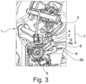
- FIG. 3 is a perspective view of the device 1 shown in a second positioning.
- the automatic start-stop system 5 is arranged in an engine compartment 6 of a vehicle, not shown in detail.
- the vehicle accordingly includes a hood, not shown, by means of which the automatic start-stop system 5 can be activated or deactivated.
- the automatic start-stop system 5 is activated when the hood is in a closed state, which is in the second positioning shown here.
- the actuating means 2 is in effective contact with the automatic start-stop system 5, so that, according to the above statements, the ignition interruption mentioned no longer occurs.
- the hood moves horizontally.
- the device 1 which is arranged operatively connected to the hood and comprises a deflection means 3, enables the actuating means 2, which is operatively connected to the device 1, to be movable essentially vertically far enough into the opening 4.
- a locking means can enable the hood to remain closed and thus the automatic start-stop system 5 to remain activated.
- the actuating means 2 interacts with a boom 8 to activate or deactivate the automatic start-stop system 5.
- Different states 9, 9a, 9b of the boom 8 are shown here. These states 9, 9a, 9b of the boom 8 can also be understood as different positionings of the boom 8. So the boom 8 is in the state 9b, so to speak, in a lowest positioning or position and in the state 9 in a top positioning or position. In state 9a, the boom 8 is arranged in a corresponding intermediate position, which is intended to represent a movement sequence of the boom 8.
Landscapes
- Engineering & Computer Science (AREA)
- Chemical & Material Sciences (AREA)
- Combustion & Propulsion (AREA)
- Mechanical Engineering (AREA)
- General Engineering & Computer Science (AREA)
- Control Of Vehicle Engines Or Engines For Specific Uses (AREA)
- Output Control And Ontrol Of Special Type Engine (AREA)
- Superstructure Of Vehicle (AREA)
Description
- Die Erfindung betrifft ein Fahrzeug nach dem Oberbegriff des Patentanspruchs 1.
- Vorrichtungen zum Aktivieren und Deaktivieren einer Start-Stopp-Automatik von Fahrzeugen sowie Fahrzeuge mit entsprechenden Vorrichtungen zum Aktivieren und Deaktivieren einer Start-Stopp-Automatik sind aus dem Stand der Technik bereits bekannt.
- Aus der
DE 199 82 154 B4 kennt man bereits ein Verfahren zur Start/Stop-Steuerung eines Kraftfahrzeuges mit automatisierbarer Kupplung. - Die
DE 102 11 466 C1 beschreibt ein Kraftfahrzeug und Verfahren zum automatisierten Abschalten und Anlassen eines Verbrennungsmotors. - Aus der
DE 10 2012 215 604 A1 ist eine mechanisch wirkende Sicherheitsanordnung für ein gewerbliches Fahrzeug und ein entsprechendes gewerbliches Fahrzeug bekannt. - In diesem Zusammenhang ist es auch bekannt, dass z.B. im Motorraum eine Vorrichtung zum Aktivieren bzw. Deaktivieren einer Start-Stopp-Automatik angeordnet ist, mittels der beispielsweise Unfallgefahren dahingehend reduziert werden sollen, als dass ein Starten des Motors bei geöffneter Motorhaube unterbunden wird. Dies resultiert daraus, dass die Start-Stopp-Automatik bei geöffneter Motorhaube deaktiviert wird, wodurch ein Starten des Motors unmöglich wird. Um einen Startvorgang des Motors durchführen zu können, ist es erforderlich, die Start-Stopp-Automatik mittels der Vorrichtung zu aktivieren. Dies erfolgt in bekannter Weise durch Schließen der Motorhaube, wobei hierdurch ein Betätigungsmittel der Vorrichtung im Wesentlichen durch vertikales Bewegen des Betätigungsmittels zu der Vorrichtung hin und von der Vorrichtung weg durchführbar ist. In entsprechender Weise wird dabei die Motorhaube, die mit dem Betätigungsmittel wirkverbunden ist, in im Wesentlichen vertikaler Richtung zum Öffnen bzw. Schließen bewegt.
- Dies ist insofern von Nachteil, dass die im Wesentlichen vertikale Bewegungsrichtung des Betätigungsmittels eine entsprechende Motorhauben-Anordnung bzw. -Ausbildung voraussetzt, d.h. die Motorhaube muss in analoger Weise im Wesentlichen vertikal bewegbar ausgebildet sein bzw. im Wesentlichen bewegt werden. Hierdurch wird die gestalterische Freiheit z.B. der Motorhauben-Anordnung bzw. die Ausbildung der Motorhaube an sich eingeschränkt, d.h. die bekannten Vorrichtungen zum Aktivieren und Deaktivieren einer Start-Stopp-Automatik eines Fahrzeugs sind nur bedingt flexibel einsetzbar.
- Aufgabe der Erfindung ist es daher, ein Fahrzeug mit einer Vorrichtung zum Aktivieren und Deaktivieren einer Start-Stopp-Automatik bereitzustellen, die mit einfachen konstruktiven Maßnahmen flexibel einsetzbar ist.
- Zur Lösung der Aufgabe wird ein Fahrzeug mit einer Vorrichtung zum Aktivieren und Deaktivieren einer Start-Stopp-Automatik des Fahrzeugs mittels einer Motorhaube vorgeschlagen, wobei die Vorrichtung zum Aktivieren und Deaktivieren der Start-Stopp-Automatik ein Betätigungsmittel umfasst.
- Erfindungsgemäß ist vorgesehen, dass das Betätigungsmittel mit wenigstens einem Umlenkmittel derart wirkverbunden ist, dass ein horizontales Bewegen der Motorhaube zu der Start-Stopp-Automatik hin und von der Start-Stopp-Automatik weg durchführbar ist.
- Aufgrund des Umlenkmittels wird trotz horizontaler Bewegung bzw. horizontalem Bewegen der Motorhaube ein im Wesentlichen vertikales Bewegen des Bewegungsmittels ermöglicht, woraus eine erhöhte Flexibilität der Vorrichtung resultieren kann. Hierdurch kann auch die Gestaltungsfreiheit der Start-Stopp-Automatik bzw. des gesamten Fahrzeugs beeinflusst werden, da es z.B. möglich wird, eine serienmäßig verbaute Start-Stopp-Automatik auch nach aufwendigen Umbauten des Fahrzeugs weiterhin verwenden zu können, was auf die erhöhte Flexibilität der Vorrichtung, insbesondere auf die Ausbildung eines Umlenkmittels daran zurückführbar ist.
- Um ein möglichst einfaches und zuverlässiges Aktivieren bzw. Deaktivieren zu ermöglichen, kann in einer besonders vorteilhaften Ausgestaltung der Erfindung vorgesehen sein, dass das Betätigungsmittel als Dorn ausgebildet ist und dass die Start-Stopp-Automatik eine Öffnung umfasst, wobei die Start-Stopp-Automatik durch Bewegung des Dorns in die Öffnung aktivierbar und durch Bewegen des Dorns aus der Öffnung deaktivierbar ist.
- In einer weiteren vorteilhaften Ausgestaltung der Erfindung kann vorgesehen sein, dass das Umlenkmittel als federbelastete Wippe ausgebildet ist. Dies stellt eine Möglichkeit dar, ein besonders einfach und sehr wirkungsvolles Umlenkmittel bereitzustellen.
- Um etwaige Toleranzen ausgleichen zu können und um somit die Zuverlässigkeit der Vorrichtung zu erhöhen, kann in einer Weiterbildung der Erfindung auch vorgesehen sein, dass das Betätigungsmittel an dem Umlenkmittel durch ein Verstellmittel verstellbar angeordnet ist.
- Das Fahrzeug kann als Wohnmobil, Reisemobil oder Reise- oder Freizeitfahrzeug ausgebildet sein.
- Aufgrund des Umlenkmittels wird ein im Wesentlichen vertikales Bewegen des Bewegungsmittels durch horizontales Bewegen der Motorhaube ermöglicht, woraus eine erhöhte Flexibilität der Vorrichtung resultieren kann. Hierdurch kann auch die Gestaltungsfreiheit der Start-Stopp-Automatik bzw. des gesamten Fahrzeugs, insbesondere der Motorhaube beeinflusst werden, da es z.B. möglich wird, eine serienmäßig verbaute Start-Stopp-Automatik auch nach aufwendigen Umbauten des Fahrzeugs weiterhin verwenden zu können, was auf die erhöhte Flexibilität der Vorrichtung zurückführbar ist.
- Dies ist weiterhin insofern besonders vorteilhaft, da das Fahrzeug als vollintegriertes Wohnmobil ausgebildet werden kann.
- Insbesondere bei vollintegrierten Wohnmobilen kann somit aufgrund deren spezieller Ausgestaltung der Motorhaube bzw. Motorhauben-Kinematik, die horizontal bewegbar ist, um geschlossen bzw. geöffnet zu werden, eine serienmäßig im Motorraum verbaute Start-Stopp-Automatik mittels einer geänderten Kinematik verwendet werden. Umbauten der Start-Stopp-Automatik sind somit nicht erforderlich. Die Start-Stopp-Automatik wird durch Schließen der Motorhaube aktiviert ist und durch Öffnen der Motorhaube deaktiviert. Dabei erfolgt eine horizontale Bewegung der Motorhaube in dessen Folge eine im Wesentlichen vertikale Bewegung des an der Vorrichtung angeordneten Betätigungsmittels erfolgt. Diese Bewegungsänderung wird durch das Umlenkmittel ermöglicht.
- Im Weiteren wird die Erfindung anhand von Zeichnungen näher beschrieben. Hierbei zeigt:
- Fig. 1:
- eine stark vereinfachte schematische Darstellung erfindungsgemäßen Vorrichtung;
- Fig. 2:
- eine perspektivische Darstellung einer erfindungsgemäßen Vorrichtung in einer ersten Positionierung;
- Fig. 3:
- die in
Fig. 1 gezeigte Vorrichtung in einer zweiten Positionierung; -
Fig. 1 eine stark vereinfachte schematische Darstellung einer erfindungsgemäßen Vorrichtung 1. Die Vorrichtung 1 ist zum - Aktivieren und Deaktivieren einer Start-Stopp-Automatik (siehe
Fig. 2 ,3 ) eines Fahrzeugs (nicht dargestellt) ausgebildet und vorgesehen. Die Vorrichtung 1 umfasst zum Aktivieren und Deaktivieren der Start-Stopp-Automatik ein Betätigungsmittel 2. Die Vorrichtung 1 ist mit einer Motorhaube (nicht gezeigt) wirkverbunden. - Weiterhin ist das Betätigungsmittel 2 mit einem Umlenkmittel 3 derart wirkverbunden, dass ein horizontales Bewegen einer Motorhaube (nicht gezeigt) dazu führt, dass das Betätigungsmittel 2 in einer im Wesentlichen vertikalen Richtung, entsprechend der Bewegungsrichtung 7 zu der Start-Stopp-Automatik (siehe
Fig. 2 ,3 ) hin bewegbar und von der Start-Stopp-Automatik (sieheFig. 2 ,3 ) wegbewegbar ist. Horizontale Bewegungen bzw. Bewegungsrichtungen (nicht gezeigt) sind dabei so zu verstehen, dass sie im Wesentlichen senkrecht bzw. orthogonal zu der Bewegungsrichtung 7 orientiert sind bzw. erfolgen. - Im gezeigten Ausführungsbeispiel ist das Betätigungsmittel 2 als Dorn ausgebildet. Das Umlenkmittel 3 ist als federbelastete Wippe ausgebildet.
- In der
Fig. 2 ist eine perspektivische Darstellung der Vorrichtung 1 in einer ersten Positionierung gezeigt. Hierbei ist anzunehmen, dass die Start-Stopp-Automatik 5 in einem Motorraum 6 eines nicht näher gezeigten Fahrzeugs angeordnet ist. Das Fahrzeug umfasst entsprechend eine nicht näher gezeigte Motorhaube, mittels der die Start-Stopp-Automatik 5 aktivierbar bzw. deaktivierbar ist. - In der Darstellung gemäß
Fig. 2 ist die Start-Stopp-Automatik 5 deaktiviert, wenn die Motorhaube in einem geöffneten Zustand vorliegt, der in der hier gezeigten ersten Positionierung vorliegt. Bei einer deaktivierten Start-Stopp-Automatik 5 ist das Betätigungsmittel 2 nicht in Wirkkontakt mit der Start-Stopp-Automatik 5, d.h. es ist nicht weit genug innerhalb der Öffnung 4 angeordnet. - Bei einer deaktivierten Start-Stopp-Automatik 5 ist ein versehentliches Starten des Motors unterbunden, wodurch etwaige Unfallgefahren hierdurch ausgeschlossen werden können. Eine deaktivierte Start-Stopp-Automatik 5 kann im Sinne der Erfindung als Zündunterbrechung aufgefasst werden.
- In der
Fig. 3 ist eine perspektivische Darstellung der Vorrichtung 1 in einer zweiten Positionierung gezeigt. Gleichermaßen ist hierbei davon auszugehen, dass die Start-Stopp-Automatik 5 in einem Motorraum 6 eines nicht näher gezeigten Fahrzeugs angeordnet ist. Das Fahrzeug umfasst entsprechend eine nicht näher gezeigte Motorhaube, mittels der die Start-Stopp-Automatik 5 aktivierbar bzw. deaktivierbar ist. - In der Darstellung gemäß
Fig. 3 ist die Start-Stopp-Automatik 5 aktiviert, wenn die Motorhaube in einem geschlossenen Zustand vorliegt, der in der hier gezeigten zweiten Positionierung vorliegt. Bei einer aktivierten Start-Stopp-Automatik 5 ist das Betätigungsmittel 2 in Wirkkontakt mit der Start-Stopp-Automatik 5, so dass gemäß obigen Ausführungen die genannte Zündunterbrechung nicht mehr vorliegt. - Um die Start-Stopp-Automatik 5 zu aktivieren, erfolgt eine horizontale Bewegung der Motorhaube. Die mit der Motorhaube wirkverbunden angeordnete Vorrichtung 1, die ein Umlenkmittel 3 umfasst, ermöglicht, dass das mit der Vorrichtung 1 wirkverbundene Betätigungsmittel 2 im Wesentlichen vertikal weit genug in die Öffnung 4 bewegbar ist. In nicht näher gezeigter Art und Weise kann ein Verschließmittel ermöglichen, dass die Motorhaube verschlossen bleibt und damit, dass die Start-Stopp-Automatik 5 aktiviert bleibt.
- Zum verbesserten Verständnis ist in der
Fig. 2 und in derFig. 3 dargestellt, dass das Betätigungsmittel 2 zur Aktivierung bzw. zur Deaktivierung der Start-Stopp-Automatik 5 mit einem Ausleger 8 interagiert. Hierbei sind jeweils verschiedene Zustände 9, 9a, 9b des Auslegers 8 dargestellt. Diese Zustände 9, 9a, 9b des Auslegers 8 können auch als unterschiedliche Positionierungen des Auslegers 8 aufgefasst werden. So ist der Ausleger 8 in dem Zustand 9b sozusagen in einer untersten Positionierung bzw. Stellung und in dem Zustand 9 in einer obersten Positionierung bzw. Stellung. In dem Zustand 9a ist der Ausleger 8 in einer entsprechenden Zwischenstellung angeordnet, die einen Bewegungsablauf des Auslegers 8 darstellen soll. -
- 1
- Vorrichtung
- 2
- Betätigungsmittel
- 3
- Umlenkmittel
- 4
- Öffnung
- 5
- Start-Stopp-Automatik
- 6
- Motorraum
- 7
- Vertikale Bewegungsrichtung
- 8
- Ausleger
- 9
- Zustand
- 9a
- Zustand
- 9b
- Zustand
Claims (5)
- Fahrzeug, wobei das Fahrzeug eine Start-Stopp-Automatik (5) umfasst, die Start-Stopp-Automatik (5) innerhalb eines Motorraums (6) des Fahrzeugs angeordnet ist und das Fahrzeug eine Vorrichtung (1) zum Aktivieren und Deaktivieren der Start-Stopp-Automatik (5) mittels einer Motorhaube umfasst sowie die Vorrichtung (1) ein Betätigungsmittel (2) umfasst,
dadurch gekennzeichnet,
dass das Betätigungsmittel (2) mit wenigstens einem Umlenkmittel (3) derart wirkverbunden ist, dass ein horizontales Bewegen der Motorhaube zu der Start-Stopp-Automatik (5) hin und von der Start-Stopp-Automatik (5) weg durchführbar ist. - Fahrzeug nach Anspruch 1,
dadurch gekennzeichnet,
dass das Betätigungsmittel (2) als Dorn ausgebildet ist und dass die Start-Stopp-Automatik (5) eine Öffnung (4) umfasst, wobei die Start-Stopp-Automatik (5) durch Bewegung des Dorns in die Öffnung (4) aktivierbar und durch Bewegen des Dorns aus der Öffnung (4) deaktivierbar ist. - Fahrzeug nach Anspruch 1 oder 2,
dadurch gekennzeichnet,
dass das Umlenkmittel (3) als federbelastete Wippe ausgebildet ist. - Fahrzeug nach einem der Ansprüche 1 bis 3,
dadurch gekennzeichnet,
dass das Betätigungsmittel (2) an dem Umlenkmittel (3) durch ein Verstellmittel verstellbar angeordnet ist. - Fahrzeug nach einem der vorhergehenden Ansprüche, wobei das Fahrzeug als Wohnmobil, Reisemobil oder Reise- oder Freizeitfahrzeug ausgebildet ist.
Priority Applications (1)
| Application Number | Priority Date | Filing Date | Title |
|---|---|---|---|
| SI201930736T SI3552900T1 (sl) | 2018-04-10 | 2019-03-26 | Naprava za aktiviranje in deaktiviranje start-stop avtomatike vozila |
Applications Claiming Priority (2)
| Application Number | Priority Date | Filing Date | Title |
|---|---|---|---|
| DE102018108500 | 2018-04-10 | ||
| DE102018111744.2A DE102018111744B3 (de) | 2018-04-10 | 2018-05-16 | Vorrichtung zum Aktivieren und Deaktivieren einer Start-Stopp-Automatik eines Fahrzeugs |
Publications (2)
| Publication Number | Publication Date |
|---|---|
| EP3552900A1 EP3552900A1 (de) | 2019-10-16 |
| EP3552900B1 true EP3552900B1 (de) | 2024-03-13 |
Family
ID=67774532
Family Applications (1)
| Application Number | Title | Priority Date | Filing Date |
|---|---|---|---|
| EP19165261.9A Active EP3552900B1 (de) | 2018-04-10 | 2019-03-26 | Vorrichtung zum aktivieren und deaktivieren einer start-stopp-automatik eines fahrzeugs |
Country Status (4)
| Country | Link |
|---|---|
| EP (1) | EP3552900B1 (de) |
| DE (1) | DE102018111744B3 (de) |
| PL (1) | PL3552900T3 (de) |
| SI (1) | SI3552900T1 (de) |
Citations (1)
| Publication number | Priority date | Publication date | Assignee | Title |
|---|---|---|---|---|
| EP1445784A1 (de) * | 2003-02-10 | 2004-08-11 | Chr. Mayr GmbH & Co. KG | Mikroschalter mit integrierter Hebelübersetzung |
Family Cites Families (5)
| Publication number | Priority date | Publication date | Assignee | Title |
|---|---|---|---|---|
| US5377641A (en) * | 1993-05-19 | 1995-01-03 | Salazar; Gerardo S. | Timer-controlled start/stop device for an automobile |
| DE19982154B4 (de) | 1998-10-28 | 2013-07-18 | Schaeffler Technologies AG & Co. KG | Verfahren zur Start/Stop-Steuerung eines Kraftfahrzeuges mit automatisierter Kupplung |
| DE10211466C1 (de) | 2002-03-15 | 2003-08-28 | Daimler Chrysler Ag | Kraftfahrzeug und Verfahren zum automatischen Abschalten und Anlassen eines Verbrennungsmotors |
| DE102012215604A1 (de) * | 2011-11-29 | 2013-05-29 | Jungheinrich Aktiengesellschaft | Mechanisch wirkende Sicherheitsanordnung für ein gewerbliches Fahrzeug und entsprechendes gewerbliches Fahrzeug |
| JP2016053330A (ja) * | 2014-09-03 | 2016-04-14 | トヨタ自動車株式会社 | エンジン再始動制御装置及びエンジン再始動禁止装置 |
-
2018
- 2018-05-16 DE DE102018111744.2A patent/DE102018111744B3/de not_active Expired - Fee Related
-
2019
- 2019-03-26 SI SI201930736T patent/SI3552900T1/sl unknown
- 2019-03-26 EP EP19165261.9A patent/EP3552900B1/de active Active
- 2019-03-26 PL PL19165261.9T patent/PL3552900T3/pl unknown
Patent Citations (1)
| Publication number | Priority date | Publication date | Assignee | Title |
|---|---|---|---|---|
| EP1445784A1 (de) * | 2003-02-10 | 2004-08-11 | Chr. Mayr GmbH & Co. KG | Mikroschalter mit integrierter Hebelübersetzung |
Also Published As
| Publication number | Publication date |
|---|---|
| SI3552900T1 (sl) | 2024-05-31 |
| DE102018111744B3 (de) | 2019-09-19 |
| PL3552900T3 (pl) | 2024-07-22 |
| EP3552900A1 (de) | 2019-10-16 |
Similar Documents
| Publication | Publication Date | Title |
|---|---|---|
| EP3612697B1 (de) | Schloss für ein kraftfahrzeug | |
| EP3612695B1 (de) | Schloss für ein kraftfahrzeug | |
| EP3253604B1 (de) | Anordnung mit einem deckel für ein fahrzeugdach | |
| DE102007035491A1 (de) | Tankklappeneinheit | |
| EP3775451B1 (de) | Kraftfahrzeugtürschloss | |
| DE102008057880B4 (de) | Vorrichtung zur Verstellung einer Klappe für ein Kraftfahrzeug | |
| EP3331742B1 (de) | Zwangsverriegelung eines frischwasseranschlusses eines schienenfahrzeugs | |
| DE102015116511A1 (de) | Werkzeugwechselvorrichtung, Verfahren und Controller für einen automatischen Werkzeugwechsel | |
| EP0230524A2 (de) | Stellvorrichtung für eine Kraftfahrzeugtür | |
| DE102018208398A1 (de) | Befüllvorrichtung für ein fahrzeug sowie fahrzeug mit einer solchen befüllvorrichtung | |
| DE102021134396A1 (de) | Abdeckvorrichtung, insbesondere ladeklappenvorrichtung | |
| EP2159461B1 (de) | Anlage zum Heben und Senken eines Fahrzeugaufbaus | |
| EP3552900B1 (de) | Vorrichtung zum aktivieren und deaktivieren einer start-stopp-automatik eines fahrzeugs | |
| DE202012007232U1 (de) | Kraftfahrzeugschlossanordnung | |
| DE102014106803B4 (de) | Anordnung mit einem Deckel für ein Fahrzeugdach | |
| DE202015105137U1 (de) | Werkzeugwechselvorrichtung und Controller für einen automatischen Werkzeugwechsel | |
| DE102014013771B4 (de) | Verstelleinrichtung zum Anheben der Hinterkante einer Frontklappe eines Kraftfahrzeugs | |
| DE102020133889A1 (de) | Kraftfahrzeug | |
| EP1076148A2 (de) | Vorrichtung zur Verriegelung einer Schiebetür | |
| WO2023169942A1 (de) | Fahrzeug mit einer rahmenlosen fahrzeugtür | |
| EP3870785B1 (de) | Kraftfahrzeugschloss, insbesondere kraftfahrzeugtürschloss | |
| EP1849940A2 (de) | Schliessvorrichtung für eine Schiebetür mit Arretierungsmittel zum Fixieren der geöffneten Schiebetür | |
| DE102016111658A1 (de) | Verschattungsvorrichtung für ein Fahrzeug | |
| DE102014216760A1 (de) | Kraftfahrzeug mit einer Heckklappenanordnung bestehend aus einer schwenkbaren unteren Heckklappe und einer schwenkbaren oberen Heckklappe | |
| DE102011115404A1 (de) | Sicherheitseinrichtung eines Fahrzeugs |
Legal Events
| Date | Code | Title | Description |
|---|---|---|---|
| PUAI | Public reference made under article 153(3) epc to a published international application that has entered the european phase |
Free format text: ORIGINAL CODE: 0009012 |
|
| STAA | Information on the status of an ep patent application or granted ep patent |
Free format text: STATUS: THE APPLICATION HAS BEEN PUBLISHED |
|
| AK | Designated contracting states |
Kind code of ref document: A1 Designated state(s): AL AT BE BG CH CY CZ DE DK EE ES FI FR GB GR HR HU IE IS IT LI LT LU LV MC MK MT NL NO PL PT RO RS SE SI SK SM TR |
|
| AX | Request for extension of the european patent |
Extension state: BA ME |
|
| STAA | Information on the status of an ep patent application or granted ep patent |
Free format text: STATUS: REQUEST FOR EXAMINATION WAS MADE |
|
| 17P | Request for examination filed |
Effective date: 20200602 |
|
| RBV | Designated contracting states (corrected) |
Designated state(s): AL AT BE BG CH CY CZ DE DK EE ES FI FR GB GR HR HU IE IS IT LI LT LU LV MC MK MT NL NO PL PT RO RS SE SI SK SM TR |
|
| STAA | Information on the status of an ep patent application or granted ep patent |
Free format text: STATUS: EXAMINATION IS IN PROGRESS |
|
| 17Q | First examination report despatched |
Effective date: 20220330 |
|
| REG | Reference to a national code |
Ref country code: DE Free format text: PREVIOUS MAIN CLASS: B60W0030180000 Ref country code: DE Ref legal event code: R079 Ref document number: 502019010768 Country of ref document: DE Free format text: PREVIOUS MAIN CLASS: B60W0030180000 Ipc: H01H0003420000 |
|
| GRAP | Despatch of communication of intention to grant a patent |
Free format text: ORIGINAL CODE: EPIDOSNIGR1 |
|
| STAA | Information on the status of an ep patent application or granted ep patent |
Free format text: STATUS: GRANT OF PATENT IS INTENDED |
|
| RIC1 | Information provided on ipc code assigned before grant |
Ipc: H01H 3/46 20060101ALI20230919BHEP Ipc: H01H 3/42 20060101AFI20230919BHEP |
|
| INTG | Intention to grant announced |
Effective date: 20231010 |
|
| GRAS | Grant fee paid |
Free format text: ORIGINAL CODE: EPIDOSNIGR3 |
|
| GRAA | (expected) grant |
Free format text: ORIGINAL CODE: 0009210 |
|
| STAA | Information on the status of an ep patent application or granted ep patent |
Free format text: STATUS: THE PATENT HAS BEEN GRANTED |
|
| AK | Designated contracting states |
Kind code of ref document: B1 Designated state(s): AL AT BE BG CH CY CZ DE DK EE ES FI FR GB GR HR HU IE IS IT LI LT LU LV MC MK MT NL NO PL PT RO RS SE SI SK SM TR |
|
| REG | Reference to a national code |
Ref country code: GB Ref legal event code: FG4D Free format text: NOT ENGLISH |
|
| REG | Reference to a national code |
Ref country code: CH Ref legal event code: EP |
|
| REG | Reference to a national code |
Ref country code: DE Ref legal event code: R096 Ref document number: 502019010768 Country of ref document: DE |
|
| REG | Reference to a national code |
Ref country code: IE Ref legal event code: FG4D Free format text: LANGUAGE OF EP DOCUMENT: GERMAN |
|
| P01 | Opt-out of the competence of the unified patent court (upc) registered |
Effective date: 20240408 |
|
| PG25 | Lapsed in a contracting state [announced via postgrant information from national office to epo] |
Ref country code: LT Free format text: LAPSE BECAUSE OF FAILURE TO SUBMIT A TRANSLATION OF THE DESCRIPTION OR TO PAY THE FEE WITHIN THE PRESCRIBED TIME-LIMIT Effective date: 20240313 |
|
| REG | Reference to a national code |
Ref country code: LT Ref legal event code: MG9D |
|
| PG25 | Lapsed in a contracting state [announced via postgrant information from national office to epo] |
Ref country code: GR Free format text: LAPSE BECAUSE OF FAILURE TO SUBMIT A TRANSLATION OF THE DESCRIPTION OR TO PAY THE FEE WITHIN THE PRESCRIBED TIME-LIMIT Effective date: 20240614 |
|
| REG | Reference to a national code |
Ref country code: NL Ref legal event code: MP Effective date: 20240313 |
|
| PG25 | Lapsed in a contracting state [announced via postgrant information from national office to epo] |
Ref country code: HR Free format text: LAPSE BECAUSE OF FAILURE TO SUBMIT A TRANSLATION OF THE DESCRIPTION OR TO PAY THE FEE WITHIN THE PRESCRIBED TIME-LIMIT Effective date: 20240313 Ref country code: RS Free format text: LAPSE BECAUSE OF FAILURE TO SUBMIT A TRANSLATION OF THE DESCRIPTION OR TO PAY THE FEE WITHIN THE PRESCRIBED TIME-LIMIT Effective date: 20240613 |
|
| PG25 | Lapsed in a contracting state [announced via postgrant information from national office to epo] |
Ref country code: ES Free format text: LAPSE BECAUSE OF FAILURE TO SUBMIT A TRANSLATION OF THE DESCRIPTION OR TO PAY THE FEE WITHIN THE PRESCRIBED TIME-LIMIT Effective date: 20240313 |
|
| PG25 | Lapsed in a contracting state [announced via postgrant information from national office to epo] |
Ref country code: RS Free format text: LAPSE BECAUSE OF FAILURE TO SUBMIT A TRANSLATION OF THE DESCRIPTION OR TO PAY THE FEE WITHIN THE PRESCRIBED TIME-LIMIT Effective date: 20240613 Ref country code: NO Free format text: LAPSE BECAUSE OF FAILURE TO SUBMIT A TRANSLATION OF THE DESCRIPTION OR TO PAY THE FEE WITHIN THE PRESCRIBED TIME-LIMIT Effective date: 20240613 Ref country code: LT Free format text: LAPSE BECAUSE OF FAILURE TO SUBMIT A TRANSLATION OF THE DESCRIPTION OR TO PAY THE FEE WITHIN THE PRESCRIBED TIME-LIMIT Effective date: 20240313 Ref country code: HR Free format text: LAPSE BECAUSE OF FAILURE TO SUBMIT A TRANSLATION OF THE DESCRIPTION OR TO PAY THE FEE WITHIN THE PRESCRIBED TIME-LIMIT Effective date: 20240313 Ref country code: GR Free format text: LAPSE BECAUSE OF FAILURE TO SUBMIT A TRANSLATION OF THE DESCRIPTION OR TO PAY THE FEE WITHIN THE PRESCRIBED TIME-LIMIT Effective date: 20240614 Ref country code: FI Free format text: LAPSE BECAUSE OF FAILURE TO SUBMIT A TRANSLATION OF THE DESCRIPTION OR TO PAY THE FEE WITHIN THE PRESCRIBED TIME-LIMIT Effective date: 20240313 Ref country code: ES Free format text: LAPSE BECAUSE OF FAILURE TO SUBMIT A TRANSLATION OF THE DESCRIPTION OR TO PAY THE FEE WITHIN THE PRESCRIBED TIME-LIMIT Effective date: 20240313 Ref country code: BG Free format text: LAPSE BECAUSE OF FAILURE TO SUBMIT A TRANSLATION OF THE DESCRIPTION OR TO PAY THE FEE WITHIN THE PRESCRIBED TIME-LIMIT Effective date: 20240313 |
|
| PG25 | Lapsed in a contracting state [announced via postgrant information from national office to epo] |
Ref country code: SE Free format text: LAPSE BECAUSE OF FAILURE TO SUBMIT A TRANSLATION OF THE DESCRIPTION OR TO PAY THE FEE WITHIN THE PRESCRIBED TIME-LIMIT Effective date: 20240313 Ref country code: LV Free format text: LAPSE BECAUSE OF FAILURE TO SUBMIT A TRANSLATION OF THE DESCRIPTION OR TO PAY THE FEE WITHIN THE PRESCRIBED TIME-LIMIT Effective date: 20240313 |
|
| PG25 | Lapsed in a contracting state [announced via postgrant information from national office to epo] |
Ref country code: NL Free format text: LAPSE BECAUSE OF FAILURE TO SUBMIT A TRANSLATION OF THE DESCRIPTION OR TO PAY THE FEE WITHIN THE PRESCRIBED TIME-LIMIT Effective date: 20240313 |
|
| PG25 | Lapsed in a contracting state [announced via postgrant information from national office to epo] |
Ref country code: NL Free format text: LAPSE BECAUSE OF FAILURE TO SUBMIT A TRANSLATION OF THE DESCRIPTION OR TO PAY THE FEE WITHIN THE PRESCRIBED TIME-LIMIT Effective date: 20240313 |
|
| PG25 | Lapsed in a contracting state [announced via postgrant information from national office to epo] |
Ref country code: IS Free format text: LAPSE BECAUSE OF FAILURE TO SUBMIT A TRANSLATION OF THE DESCRIPTION OR TO PAY THE FEE WITHIN THE PRESCRIBED TIME-LIMIT Effective date: 20240713 |
|
| PG25 | Lapsed in a contracting state [announced via postgrant information from national office to epo] |
Ref country code: PT Free format text: LAPSE BECAUSE OF FAILURE TO SUBMIT A TRANSLATION OF THE DESCRIPTION OR TO PAY THE FEE WITHIN THE PRESCRIBED TIME-LIMIT Effective date: 20240715 Ref country code: SM Free format text: LAPSE BECAUSE OF FAILURE TO SUBMIT A TRANSLATION OF THE DESCRIPTION OR TO PAY THE FEE WITHIN THE PRESCRIBED TIME-LIMIT Effective date: 20240313 |
|
| PG25 | Lapsed in a contracting state [announced via postgrant information from national office to epo] |
Ref country code: CZ Free format text: LAPSE BECAUSE OF FAILURE TO SUBMIT A TRANSLATION OF THE DESCRIPTION OR TO PAY THE FEE WITHIN THE PRESCRIBED TIME-LIMIT Effective date: 20240313 Ref country code: EE Free format text: LAPSE BECAUSE OF FAILURE TO SUBMIT A TRANSLATION OF THE DESCRIPTION OR TO PAY THE FEE WITHIN THE PRESCRIBED TIME-LIMIT Effective date: 20240313 |
|
| PG25 | Lapsed in a contracting state [announced via postgrant information from national office to epo] |
Ref country code: SK Free format text: LAPSE BECAUSE OF FAILURE TO SUBMIT A TRANSLATION OF THE DESCRIPTION OR TO PAY THE FEE WITHIN THE PRESCRIBED TIME-LIMIT Effective date: 20240313 |
|
| PG25 | Lapsed in a contracting state [announced via postgrant information from national office to epo] |
Ref country code: SM Free format text: LAPSE BECAUSE OF FAILURE TO SUBMIT A TRANSLATION OF THE DESCRIPTION OR TO PAY THE FEE WITHIN THE PRESCRIBED TIME-LIMIT Effective date: 20240313 Ref country code: SK Free format text: LAPSE BECAUSE OF FAILURE TO SUBMIT A TRANSLATION OF THE DESCRIPTION OR TO PAY THE FEE WITHIN THE PRESCRIBED TIME-LIMIT Effective date: 20240313 Ref country code: RO Free format text: LAPSE BECAUSE OF FAILURE TO SUBMIT A TRANSLATION OF THE DESCRIPTION OR TO PAY THE FEE WITHIN THE PRESCRIBED TIME-LIMIT Effective date: 20240313 Ref country code: PT Free format text: LAPSE BECAUSE OF FAILURE TO SUBMIT A TRANSLATION OF THE DESCRIPTION OR TO PAY THE FEE WITHIN THE PRESCRIBED TIME-LIMIT Effective date: 20240715 Ref country code: IS Free format text: LAPSE BECAUSE OF FAILURE TO SUBMIT A TRANSLATION OF THE DESCRIPTION OR TO PAY THE FEE WITHIN THE PRESCRIBED TIME-LIMIT Effective date: 20240713 Ref country code: EE Free format text: LAPSE BECAUSE OF FAILURE TO SUBMIT A TRANSLATION OF THE DESCRIPTION OR TO PAY THE FEE WITHIN THE PRESCRIBED TIME-LIMIT Effective date: 20240313 Ref country code: CZ Free format text: LAPSE BECAUSE OF FAILURE TO SUBMIT A TRANSLATION OF THE DESCRIPTION OR TO PAY THE FEE WITHIN THE PRESCRIBED TIME-LIMIT Effective date: 20240313 |
|
| REG | Reference to a national code |
Ref country code: CH Ref legal event code: PL |
|
| PG25 | Lapsed in a contracting state [announced via postgrant information from national office to epo] |
Ref country code: LU Free format text: LAPSE BECAUSE OF NON-PAYMENT OF DUE FEES Effective date: 20240326 |
|
| PG25 | Lapsed in a contracting state [announced via postgrant information from national office to epo] |
Ref country code: LU Free format text: LAPSE BECAUSE OF NON-PAYMENT OF DUE FEES Effective date: 20240326 |
|
| REG | Reference to a national code |
Ref country code: DE Ref legal event code: R097 Ref document number: 502019010768 Country of ref document: DE Ref country code: BE Ref legal event code: MM Effective date: 20240331 |
|
| PG25 | Lapsed in a contracting state [announced via postgrant information from national office to epo] |
Ref country code: MC Free format text: LAPSE BECAUSE OF FAILURE TO SUBMIT A TRANSLATION OF THE DESCRIPTION OR TO PAY THE FEE WITHIN THE PRESCRIBED TIME-LIMIT Effective date: 20240313 |
|
| PG25 | Lapsed in a contracting state [announced via postgrant information from national office to epo] |
Ref country code: DK Free format text: LAPSE BECAUSE OF FAILURE TO SUBMIT A TRANSLATION OF THE DESCRIPTION OR TO PAY THE FEE WITHIN THE PRESCRIBED TIME-LIMIT Effective date: 20240313 |
|
| PG25 | Lapsed in a contracting state [announced via postgrant information from national office to epo] |
Ref country code: BE Free format text: LAPSE BECAUSE OF NON-PAYMENT OF DUE FEES Effective date: 20240331 |
|
| PLBE | No opposition filed within time limit |
Free format text: ORIGINAL CODE: 0009261 |
|
| STAA | Information on the status of an ep patent application or granted ep patent |
Free format text: STATUS: NO OPPOSITION FILED WITHIN TIME LIMIT |
|
| PG25 | Lapsed in a contracting state [announced via postgrant information from national office to epo] |
Ref country code: IE Free format text: LAPSE BECAUSE OF NON-PAYMENT OF DUE FEES Effective date: 20240326 |
|
| PG25 | Lapsed in a contracting state [announced via postgrant information from national office to epo] |
Ref country code: MC Free format text: LAPSE BECAUSE OF FAILURE TO SUBMIT A TRANSLATION OF THE DESCRIPTION OR TO PAY THE FEE WITHIN THE PRESCRIBED TIME-LIMIT Effective date: 20240313 Ref country code: IE Free format text: LAPSE BECAUSE OF NON-PAYMENT OF DUE FEES Effective date: 20240326 Ref country code: DK Free format text: LAPSE BECAUSE OF FAILURE TO SUBMIT A TRANSLATION OF THE DESCRIPTION OR TO PAY THE FEE WITHIN THE PRESCRIBED TIME-LIMIT Effective date: 20240313 Ref country code: BE Free format text: LAPSE BECAUSE OF NON-PAYMENT OF DUE FEES Effective date: 20240331 Ref country code: CH Free format text: LAPSE BECAUSE OF NON-PAYMENT OF DUE FEES Effective date: 20240331 |
|
| 26N | No opposition filed |
Effective date: 20241216 |
|
| GBPC | Gb: european patent ceased through non-payment of renewal fee |
Effective date: 20240613 |
|
| PGFP | Annual fee paid to national office [announced via postgrant information from national office to epo] |
Ref country code: SI Payment date: 20250313 Year of fee payment: 7 |
|
| PG25 | Lapsed in a contracting state [announced via postgrant information from national office to epo] |
Ref country code: GB Free format text: LAPSE BECAUSE OF NON-PAYMENT OF DUE FEES Effective date: 20240613 |
|
| REG | Reference to a national code |
Ref country code: AT Ref legal event code: MM01 Ref document number: 1666564 Country of ref document: AT Kind code of ref document: T Effective date: 20240326 |
|
| PGFP | Annual fee paid to national office [announced via postgrant information from national office to epo] |
Ref country code: IT Payment date: 20250331 Year of fee payment: 7 |
|
| PG25 | Lapsed in a contracting state [announced via postgrant information from national office to epo] |
Ref country code: AT Free format text: LAPSE BECAUSE OF NON-PAYMENT OF DUE FEES Effective date: 20240326 |
|
| PG25 | Lapsed in a contracting state [announced via postgrant information from national office to epo] |
Ref country code: CY Free format text: LAPSE BECAUSE OF FAILURE TO SUBMIT A TRANSLATION OF THE DESCRIPTION OR TO PAY THE FEE WITHIN THE PRESCRIBED TIME-LIMIT; INVALID AB INITIO Effective date: 20190326 |
|
| PG25 | Lapsed in a contracting state [announced via postgrant information from national office to epo] |
Ref country code: HU Free format text: LAPSE BECAUSE OF FAILURE TO SUBMIT A TRANSLATION OF THE DESCRIPTION OR TO PAY THE FEE WITHIN THE PRESCRIBED TIME-LIMIT; INVALID AB INITIO Effective date: 20190326 |
|
| PG25 | Lapsed in a contracting state [announced via postgrant information from national office to epo] |
Ref country code: TR Free format text: LAPSE BECAUSE OF FAILURE TO SUBMIT A TRANSLATION OF THE DESCRIPTION OR TO PAY THE FEE WITHIN THE PRESCRIBED TIME-LIMIT Effective date: 20240313 |
|
| PGFP | Annual fee paid to national office [announced via postgrant information from national office to epo] |
Ref country code: DE Payment date: 20251212 Year of fee payment: 8 |
|
| PGFP | Annual fee paid to national office [announced via postgrant information from national office to epo] |
Ref country code: FR Payment date: 20260325 Year of fee payment: 8 |
|
| PGFP | Annual fee paid to national office [announced via postgrant information from national office to epo] |
Ref country code: PL Payment date: 20260318 Year of fee payment: 8 |