EP3552799A1 - Tête d'outil pour extrudeuse de profilés creux - Google Patents
Tête d'outil pour extrudeuse de profilés creux Download PDFInfo
- Publication number
- EP3552799A1 EP3552799A1 EP19163425.2A EP19163425A EP3552799A1 EP 3552799 A1 EP3552799 A1 EP 3552799A1 EP 19163425 A EP19163425 A EP 19163425A EP 3552799 A1 EP3552799 A1 EP 3552799A1
- Authority
- EP
- European Patent Office
- Prior art keywords
- tool
- mandrel
- tool head
- extruder
- extrusion
- Prior art date
- Legal status (The legal status is an assumption and is not a legal conclusion. Google has not performed a legal analysis and makes no representation as to the accuracy of the status listed.)
- Granted
Links
- 238000001125 extrusion Methods 0.000 claims abstract description 53
- 238000009826 distribution Methods 0.000 claims abstract description 10
- 239000000463 material Substances 0.000 claims description 16
- 238000004891 communication Methods 0.000 claims description 9
- 230000001105 regulatory effect Effects 0.000 claims description 6
- 238000004519 manufacturing process Methods 0.000 abstract description 2
- 241000196324 Embryophyta Species 0.000 description 14
- 238000001816 cooling Methods 0.000 description 5
- 238000006073 displacement reaction Methods 0.000 description 4
- 238000012423 maintenance Methods 0.000 description 4
- 238000004140 cleaning Methods 0.000 description 3
- 239000011248 coating agent Substances 0.000 description 3
- 238000000576 coating method Methods 0.000 description 3
- 238000001514 detection method Methods 0.000 description 3
- 239000012530 fluid Substances 0.000 description 3
- 229920001296 polysiloxane Polymers 0.000 description 3
- 230000005540 biological transmission Effects 0.000 description 2
- 230000000295 complement effect Effects 0.000 description 2
- 239000012809 cooling fluid Substances 0.000 description 2
- 238000004663 powder metallurgy Methods 0.000 description 2
- 238000012545 processing Methods 0.000 description 2
- 230000001953 sensory effect Effects 0.000 description 2
- 238000005496 tempering Methods 0.000 description 2
- 241000309551 Arthraxon hispidus Species 0.000 description 1
- 230000001276 controlling effect Effects 0.000 description 1
- 239000000498 cooling water Substances 0.000 description 1
- 238000013461 design Methods 0.000 description 1
- 230000000694 effects Effects 0.000 description 1
- 238000005516 engineering process Methods 0.000 description 1
- 238000000265 homogenisation Methods 0.000 description 1
- 238000005259 measurement Methods 0.000 description 1
- 230000002093 peripheral effect Effects 0.000 description 1
- 229920000098 polyolefin Polymers 0.000 description 1
- 238000007493 shaping process Methods 0.000 description 1
- 230000001360 synchronised effect Effects 0.000 description 1
- 229920001169 thermoplastic Polymers 0.000 description 1
- 239000012815 thermoplastic material Substances 0.000 description 1
- 239000004416 thermosoftening plastic Substances 0.000 description 1
- 230000007704 transition Effects 0.000 description 1
- XLYOFNOQVPJJNP-UHFFFAOYSA-N water Substances O XLYOFNOQVPJJNP-UHFFFAOYSA-N 0.000 description 1
Images


Classifications
-
- B—PERFORMING OPERATIONS; TRANSPORTING
- B29—WORKING OF PLASTICS; WORKING OF SUBSTANCES IN A PLASTIC STATE IN GENERAL
- B29C—SHAPING OR JOINING OF PLASTICS; SHAPING OF MATERIAL IN A PLASTIC STATE, NOT OTHERWISE PROVIDED FOR; AFTER-TREATMENT OF THE SHAPED PRODUCTS, e.g. REPAIRING
- B29C48/00—Extrusion moulding, i.e. expressing the moulding material through a die or nozzle which imparts the desired form; Apparatus therefor
- B29C48/25—Component parts, details or accessories; Auxiliary operations
- B29C48/30—Extrusion nozzles or dies
- B29C48/32—Extrusion nozzles or dies with annular openings, e.g. for forming tubular articles
- B29C48/325—Extrusion nozzles or dies with annular openings, e.g. for forming tubular articles being adjustable, i.e. having adjustable exit sections
- B29C48/327—Extrusion nozzles or dies with annular openings, e.g. for forming tubular articles being adjustable, i.e. having adjustable exit sections with centering means
-
- B—PERFORMING OPERATIONS; TRANSPORTING
- B29—WORKING OF PLASTICS; WORKING OF SUBSTANCES IN A PLASTIC STATE IN GENERAL
- B29C—SHAPING OR JOINING OF PLASTICS; SHAPING OF MATERIAL IN A PLASTIC STATE, NOT OTHERWISE PROVIDED FOR; AFTER-TREATMENT OF THE SHAPED PRODUCTS, e.g. REPAIRING
- B29C48/00—Extrusion moulding, i.e. expressing the moulding material through a die or nozzle which imparts the desired form; Apparatus therefor
- B29C48/25—Component parts, details or accessories; Auxiliary operations
- B29C48/256—Exchangeable extruder parts
- B29C48/2562—Mounting or handling of the die
-
- B—PERFORMING OPERATIONS; TRANSPORTING
- B29—WORKING OF PLASTICS; WORKING OF SUBSTANCES IN A PLASTIC STATE IN GENERAL
- B29C—SHAPING OR JOINING OF PLASTICS; SHAPING OF MATERIAL IN A PLASTIC STATE, NOT OTHERWISE PROVIDED FOR; AFTER-TREATMENT OF THE SHAPED PRODUCTS, e.g. REPAIRING
- B29C2948/00—Indexing scheme relating to extrusion moulding
- B29C2948/92—Measuring, controlling or regulating
- B29C2948/92009—Measured parameter
- B29C2948/92114—Dimensions
- B29C2948/92152—Thickness
-
- B—PERFORMING OPERATIONS; TRANSPORTING
- B29—WORKING OF PLASTICS; WORKING OF SUBSTANCES IN A PLASTIC STATE IN GENERAL
- B29C—SHAPING OR JOINING OF PLASTICS; SHAPING OF MATERIAL IN A PLASTIC STATE, NOT OTHERWISE PROVIDED FOR; AFTER-TREATMENT OF THE SHAPED PRODUCTS, e.g. REPAIRING
- B29C48/00—Extrusion moulding, i.e. expressing the moulding material through a die or nozzle which imparts the desired form; Apparatus therefor
- B29C48/03—Extrusion moulding, i.e. expressing the moulding material through a die or nozzle which imparts the desired form; Apparatus therefor characterised by the shape of the extruded material at extrusion
- B29C48/09—Articles with cross-sections having partially or fully enclosed cavities, e.g. pipes or channels
Definitions
- the invention relates to a tool head for a hollow-section extruder, in particular for a hose extruder. Furthermore, the invention relates to a tool head assembly with such a tool head, an extruder with such a tool head or such a tool head assembly and an extrusion line with such an extruder.
- a silicone extruder is known from the WO 2005/039847 A1
- a tool head in the form of a hose extrusion head is known from DE 10 2014 103 521 B3 , of the EP 0 075 809 A1 , of the EP 2 768 653 B1 and the DE 197 24 692 A1 ,
- a specification of a circumferential distribution of a width of the extrusion annular channel which corresponds to a circumferential distribution of a hollow profile thickness to be extruded, in particular a tube thickness, is achieved by means of a predefinable tilting of the tool mandrel relative to the tool ring.
- a relative position of a hollow section to be extruded or hose jacket wall which is specified by the outer boundary of the extrusion ring channel, ie by the position of the tool ring, remains independent of the tool mandrel tilt position.
- the extrusion annulus may follow a heart curve.
- a material flow path for the material to be extruded, which opens into the extrusion ring channel, can be formed in a distributor body which is mounted in the head housing of the tool head. At least one cooling channel for cooling the tool head can be arranged in the head housing.
- the tilting joint over which the mandrel carrier is tiltable relative to the tool ring, may have hardened surfaces.
- the tilting joint may have powder metallurgy treated surfaces. At least one of the surfaces of the tilting joint may have a lubricious coating.
- the tool mandrel and / or the tool ring can be designed as replacement parts. To equip the tool head, a set with different pairings of a respective tool mandrel and a respective tool ring or a set with a plurality of tool mandrels / tool rings, which are adapted to a tool ring / tool mandrel include.
- a holder of the tool ring from the axial adjustment housing body against the direction of the force of the extrusion pressure makes it possible, for example, via a specification of an axial position of the axial adjustment housing body to specify an axial position of the tool ring to the tool mandrel.
- Such Axial somnsvorgabe allows adjustment of averaged over the circumference of the width of the extrusion annular channel.
- the axial adjustment housing body may be designed as a centering nut.
- the axial adjustment housing body may be mounted in a receptacle which in turn is mounted to the housing.
- An embodiment according to claim 2 utilizes a lever effect of the mandrel carrier for tilting the tool mandrel.
- a distance of the centering device to the tilting joint can be greater than a distance between the tilting joint and a nozzle outlet of the extrusion annular channel. For example, this distance may be more than 1, 1, more than 1.2, more than 1.25, more than 1.5, more than 2, more than that 3 times or even more than 5 times the distance between the tilting joint and the nozzle opening amount.
- Centering actuators according to claim 3 have proven themselves for setting a tilting position of the tool mandrel.
- the centering actuators can be designed as centering.
- the centering device can be carried by a centering ring, which in turn is mounted on the head housing.
- the centering ring can be mounted on the distributor body.
- a housing-side internal thread, which is designed to be complementary to the respective centering actuator, may be part of a centering bush fixedly connected to the head housing.
- a ball joint according to claim 4 has proven to be a tilting joint for stepless specification of the tilt position of the tool mandrel relative to the tool ring.
- the ball joint can with a given tolerance between the joint parts, ie a joint head or a dome part and a joint socket or a socket part, be executed.
- a socket part of the ball joint may be arranged on the housing side.
- the socket part can be embodied in a distributor body mounted in the housing and / or in a centering ring of the centering device or else directly in the head housing.
- a holder of the tool ring according to claim 6 avoids undesirable load peaks in the transmission of the extrusion pressure from the tool ring on the axial adjustment housing body.
- the advantages of a tool assembly according to claim 7 correspond to those which have already been explained above with reference to the tool head. Due to the control / regulating device, it is possible with the tool head assembly controlled certain parameters of the tube to be extruded or controlled to keep within predetermined tolerance limits. In particular, a closed-loop control can be realized.
- the at least one actuator of the centering device can be realized in the form of one or more motor-driven centering screws.
- the at least one actuator can be designed as a stepper motor.
- the at least one actuator can interact with a planetary gear.
- the control device can also cooperate with an actuator which acts on the axial adjustment housing body for the adjustment of this.
- the actuator can be designed as a stepping motor and can act on the centering nut via a planetary gear.
- the sensor may be a sensor for measuring a wall thickness of the tube extruded with the tool head.
- the sensor can be designed as a radiometric sensor, for example as an X-ray sensor. Alternatively or additionally, the sensor may be designed as a microwave or as an ultrasonic sensor.
- the control / regulating device can additionally detect a plurality of further input variables of the extruder and / or the extrusion plant and pass control signals to drive units or actuators of the extruder and the extrusion plant for controlling and / or regulating corresponding parameters. In particular, the maintenance of a constant feed pressure has proven particularly advantageous for the extrusion result.
- the input variables may be an actual feed temperature of the extrusion material or else a discharge pressure of the extruded mass in the region of the tool head or else a discharge temperature.
- the feeder of the extrusion plant may be a feeder with a feed screw and a hopper.
- the charging device according to this further aspect may also be constructed differently.
- the extruder may be a silicone extruder and / or an extruder for a thermoplastic material or for a polyolefin material.
- An extruded hollow profile or an extruded tube can be used in particular in medical technology.
- An extrusion plant 1 has an extruder 2 and a charging device 3 for feeding the extruder 2 with mass to be extruded.
- the mass to be extruded may be silicone.
- the mass to be extruded may also be another material, for example a thermoplastic.
- the extruder 2 is designed as a hollow-section extruder and in the illustrated embodiment as a tube extruder.
- the charging device 3 has a top task box 4, which opens on the bottom side in a hopper 5. The latter in turn opens into a bottom-side feed opening 6.
- the mass feed opening 6 is in fluid communication via a feed channel 7 with a feed zone of the extruder 2.
- FIG. 1 shows an embodiment of the charging device with upright feed hopper 5.
- An alternative embodiment, not shown, has a sloping feed hopper. 5
- the extruder 2 can be designed as a single-screw or as a twin-screw extruder.
- Part of the charging device 3 is a feed screw, not shown.
- the latter is mounted axially and radially on a frame housing 8 of the extrusion plant 1.
- the feeding hopper 5 is designed rotatably drivable. Near the feed opening 6, the feed hopper 5 is again mounted axially and radially relative to the frame housing 8.
- the two rotary drives for the feed screw on the one hand and the hopper 5 on the other hand are executed independently.
- a common drive for the feed screw on the one hand and the hopper 5 on the other hand be present, a predetermined speed ratio between a feed screw speed on the one hand and a hopper speed on the other hand via a transmission or reduction gear of such a common drive can be specified ,
- the rotary drives or the common drive for the feed screw and the hopper 5 can be designed as a synchronous motor.
- the charging device 3 is cooled with cooling water, which may be circulated.
- FIG. 1 shows the feeder 3 in a feed position, ie in an operating position for feeding the mass to be extruded via the feed box 4, the hopper 5, the feed opening 6 and the feed channel 7 toward the feed zone of the extruder. 2
- the feeder 3 may be in a relative to the loading position of FIG. 1 be pivoted about a vertical pivot axis swung and along this pivot axis linearly downwardly displaced cleaning or maintenance position. This swung cleaning or maintenance position is not shown in the drawing. Both the pivoting and the displacement movement are guided in a displacement frame section 9 of the frame housing 8.
- a flange connection 10 is released between two sections of the charging channel 7.
- the extrusion plant 1 has a central controller 11 with an operating terminal 12.
- the controller 11 is in signal communication with the two rotary drives of the feed screw and the hopper 5.
- a feed pressure sensor BDS (see FIG. Fig. 3 ) arranged in a transition region between the charging device 3 and the extruder 2, that is in the region of the feed channel 7, a feed pressure sensor BDS (see FIG. Fig. 3 ) arranged.
- the latter serves for Measuring an actual feed pressure of the mass to be extruded.
- the pressure sensor BDS is arranged so that a sensor signal of the pressure sensor BDS for regulating a pressure of the mass to be extruded can be generated directly in front of the feed zone of the extruder 2.
- the pressure sensor BDS can be arranged directly adjacent to the intake zone.
- Part of the controller 11 is one in the FIG. 1 schematically indicated control unit 13 (see also the signal processing scheme according to Fig. 3 ) which is in signal communication with the feed pressure sensor BDS and the feed drive means, that is, the feed rotary drive BDA and / or the hopper rotary drive ADA.
- the control unit 13 is used to specify a desired feed pressure and to forward an actuating signal to the feed drive unit BDA depending on a determined difference between the desired feed pressure and the actual feed pressure.
- a feed temperature sensor BTS for measuring an actual feed temperature of the mass to be extruded is further arranged.
- the charging temperature sensor BTS is in signal communication with the control unit 13.
- the latter is used to measure an actual discharge pressure of the mass to be extruded.
- the control unit 13 is in signal communication with the tool head pressure sensor 15 and an extruder drive unit 16.
- the extruder drive unit 16 serves to drive at least an extruder screw running in a housing cylinder 17 of the extruder 2.
- the control unit 13 also serves to specify a desired discharge pressure of the mass to be extruded and to forward a corresponding control signal to the extruder drive unit 16 as a function of a determined difference between the desired discharge pressure and the actual discharge pressure.
- the extrusion system 1 furthermore has a discharge temperature sensor 18, which is likewise arranged in the tool head 14 of the extruder 2.
- the discharge temperature sensor 18 serves to measure an actual discharge temperature of the mass to be extruded.
- the discharge temperature sensor 18 is in signal communication with the control unit 13.
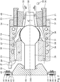
- Fig. 2 shows details of the tool head 14 in an axial longitudinal section.
- the tool head 14 has a head housing 19, in which a material or mass flow path 20 is predetermined, the outlet nozzle side opens into an extrusion annular channel 21.
- the extrusion annular channel 21 is bounded on the inside by a tool mandrel 22 and is limited to the outside by a tool ring 23.
- a longitudinal axis LE of the extruder 2 can be a longitudinal axis LWK of the tool head 14 in alignment, parallel or, as in the described embodiment, perpendicular thereto.
- the longitudinal axis LWK of the tool head 14 thus extends radially to the longitudinal axis LE of the extruder 2.
- a material inlet 24 of the extruder 2 thus extends through a jacket wall 25 of the head housing 19, as in the Fig. 2 indicated schematically.
- This material inlet 24 forms an inlet channel which is in fluid communication with the extrusion annular channel 21 via a distribution channel 26 and the material flow path 20.
- the tool mandrel 22 is supported and held by a housing-side mandrel carrier 27.
- the mandrel carrier 27 has a dome-shaped mandrel-joint portion 28 and a tilt rod portion 29.
- a centering device 30 is arranged, which will be even closer is explained.
- the mandrel carrier 27 is tiltably mounted relative to the tool ring 23 by two degrees of freedom via a tilting joint.
- the tilting joint is formed on the one hand by the mandrel-joint portion 28 as a dome part and a complementary thereto designed cup portion 31 of a manifold body 32, as a pan part.
- the distributor body 32 is mounted in the housing housing 19 fixed to the housing.
- the tilting joint 28, 31 is designed as a ball joint. Between the two joint parts of the ball joint 28, 31, so the mandrel joint portion 28 and the manifold pan portion 31, a predetermined component game, for example, be performed in the range between 50 microns and 200 microns.
- the dome part of the ball joint 28, 31 thus the mandrel joint portion may be integrally formed on the tilt rod portion 29 of the mandrel support 27.
- the tilting joint 28, 31 can be hardened Have surfaces on the mandrel hinge portion 28 and / or on the distributor pan portion 31. These may be surfaces treated with powder metallurgy.
- the sections 28, 31 of the tilting joint may have a sliding coating.
- the tiltability of the mandrel carrier 27 relative to the tool ring 23 via the tilting joint 28, 31 is such that depending on the tilt position of the mandrel carrier 27, a circumferential distribution of a width RK of the extrusion annular channel 21 between a nozzle-side portion of the tool mandrel 22 and the tool ring 23 can be predetermined.
- a circumferential distribution of a width RK of the extrusion annular channel 21 between a nozzle-side portion of the tool mandrel 22 and the tool ring 23 can be predetermined.
- a predetermined distribution of the width RK of the extrusion ring channel 21 in the circumferential direction about the longitudinal axis LWK of the tool head 14. This is a homogenization of a hose wall thickness of one extruded with the extruder 2 Hose in the circumferential direction possible.
- a displacement of the tool ring 23 is not required.
- the material flow path 20 between the material inlet 24 and the extrusion annular channel 21 can follow a heart curve.
- the expert finds for example in the textbook “ Handbuch Urformen - Edition Handbuch der Vietnamesestechnik "(second edition, 2003, Carl Hanser Verlag, publisher Bührig-Polaczek et al.).
- Cooling fluid can generally be a tempering fluid for tempering the tool head 14, ie for holding the tool head 14 at a predetermined temperature.
- the tool mandrel 22 and / or the tool ring 23 can be designed as replacement parts.
- different pairings of one type each of the tool mandrel 22 and one type of tool ring 23 can be predeterminable.
- the scope of delivery of the tool head 14 may accordingly include a set of several such pairings of tool mandrel / tool ring.
- the tool mandrel 22 may be releasably connected to the mandrel carrier 27, for example via a screw connection.
- the tool ring 23 may be held against an extrusion direction ER by an axial adjustment housing body 35.
- the latter can be screwed by a thread 36 with an adjusting portion 37 of the head housing 19.
- the axial adjustment housing body 35 may be designed as a centering nut.
- the setting section 37 represents a receptacle for the axial adjustment housing body 35.
- a specification of an axial position of the axial adjustment housing body 35 relative to the head housing 19 makes it possible to specify an axial position of the tool ring 23 relative to the tool mandrel 22.
- the tool ring 23 is floatingly received in the axial adjustment housing body 35.
- This specification of the axial position, in conjunction with a conical shaping of the tool mandrel 22 and / or the tool ring 23 in the region of the extrusion ring channel 21, enables setting of a width RK average of the circumference of the extrusion ring channel 21 Extrusion annular channel 21.
- axial position of the tool ring 23 relative to the tool mandrel 22 can thus specify a wall thickness of the tube to be extruded.
- the centering device 30 has a plurality of centering actuators in the form of centering screws 38, of which in the FIG. 2 schematically two centering 38 are shown.
- the centering screws 38 extend radially to the longitudinal axis LWK of the tool head 14 and thus to a good approximation also radially to the longitudinal axis of the mandrel carrier 27.
- the centering screws 38 are mounted on the head housing 19 in a manner not shown.
- the centering screws 38 may be screwed into ring portions 39 of an otherwise not shown centering ring, which in turn is mounted on the head housing 19 and / or on the manifold body 32.
- An internal thread of the ring portion 39 may also be part of a separate from the head housing 19 and firmly connected with this centering, which in the Fig. 2 indicated at 40.
- Free ends 41 of the centering screws 38 abut against a peripheral wall 42 of a centering head 43 of the mandrel carrier 27.
- the centering head 43 is fixedly connected to the tilting rod portion 29 of the mandrel carrier 27 and may be an integral part of the tilting rod portion 29.
- the respective tilt position ie the position of the longitudinal axis of the mandrel carrier 27 to the longitudinal axis of the entire tool head 14, are specified. It can, for example, three or more centering 38 on the type of in the Fig.
- the centering screws 38 can be driven by means of corresponding, respectively associated rotary actuators 44 motor.
- a tool head assembly 45 which is part of the tool head 14, may additionally include at least one sensor 46 for measuring a wall thickness of the extruded with the tool head hose.
- the wall thickness sensor 46 can be designed as a radiometric sensor, for example as an X-ray sensor. Both the rotary actuators 44, which then represent actuators of the centering device 30, and the at least one wall thickness sensor 46 are in signal communication with the controller 11 and the control unit 13 (see also Fig. 3 ).
- An adjustment of the average width of the extrusion ring channel 21 can in particular be made steplessly with an accuracy in the range of 1/100 millimeter.
- THz waves can also take place.
- a wall thickness of a tube to be extruded can be set to a predetermined value with a tolerance that is less than 100 microns, which may be less than 50 microns, which may be less than 30 microns, which may be less than 20 microns and also may be less than 10 microns.
- thermosensors In variants of the extrusion plant 1, it is also possible to use a plurality of feed pressure sensors and / or a plurality of feed temperature sensors and / or a plurality of tool head pressure sensors and / or a plurality of discharge temperature sensors.
- Various temperature sensors can be arranged in particular in different temperature zones of the extruder 2.
- a temperature in the at least one temperature zone in the conveying path of the extrudate mass of the extrusion plant 1 can be predetermined via a temperature control medium.
- a temperature control medium for example water, and in particular cooled.
- Another controlled variable which can be kept constant by comparing a measured actual value with a predetermined desired value via the control unit 13, is a material throughput in the conveying path of the extrusion plant 1. This throughput can be measured at different points of the entire conveying path between the charging device 3 and the tool head 14 become.
- the mass to be extruded is first introduced into the charging device 3. Subsequently, the mass to be extruded is conveyed through the charging device 3 and the extruder 2. The extrudate produced is then discharged from the extruder 2 in profile or tubular form via the tool head 14.
- These control signals of the control unit 13 can on the hopper rotational drive ADA and / or on the screw rotary drive BDA and / or on the extruder drive unit 16 and / or on actuating components of the tool head 24, for example, the actuators 44 of the centering device 30 act.
- a rotational speed of the feed hopper 5 a rotational speed of the feed screw and / or a screw speed of the extruder 2 can be predetermined or manipulated variables of adjustable components of the tool head 24, such as the circumferential distribution and / or the mean value of the width RK of the extrusion, can be selected -Ringkanals 21 pretend.
- Drives of the extrusion system 1, especially the rotary actuators 10, 15, 44 and the extrusion drive 16, can be designed to be infinitely variable.
- a tilt position specification in the region of the centering head 43 can also be effected via linearly displaceable reciprocating pistons.
- Drives of the centering device can be designed as electric motors or hydraulic cylinders.
- a cooling of the tool head 14 can be controlled or regulated and, in particular, depending on the material throughput, a Shore hardness of the material and depending on the respective design of the material flow path 20 on the one hand in the region of the manifold body 32 and on the other hand in the region of the nozzle-side outlet in the extrusion annular channel.
Landscapes
- Engineering & Computer Science (AREA)
- Mechanical Engineering (AREA)
- Manufacturing & Machinery (AREA)
- Extrusion Moulding Of Plastics Or The Like (AREA)
Priority Applications (1)
| Application Number | Priority Date | Filing Date | Title |
|---|---|---|---|
| PL19163425T PL3552799T3 (pl) | 2018-03-28 | 2019-03-18 | Głowica formująca do wytłaczarki wydrążonych profili |
Applications Claiming Priority (1)
| Application Number | Priority Date | Filing Date | Title |
|---|---|---|---|
| DE102018204729.4A DE102018204729A1 (de) | 2018-03-28 | 2018-03-28 | Werkzeugkopf für einen Hohlprofil-Extruder |
Publications (2)
| Publication Number | Publication Date |
|---|---|
| EP3552799A1 true EP3552799A1 (fr) | 2019-10-16 |
| EP3552799B1 EP3552799B1 (fr) | 2021-05-05 |
Family
ID=65818318
Family Applications (1)
| Application Number | Title | Priority Date | Filing Date |
|---|---|---|---|
| EP19163425.2A Active EP3552799B1 (fr) | 2018-03-28 | 2019-03-18 | Tête d'outil pour extrudeuse de profilés creux |
Country Status (6)
| Country | Link |
|---|---|
| US (1) | US20190299514A1 (fr) |
| EP (1) | EP3552799B1 (fr) |
| DE (1) | DE102018204729A1 (fr) |
| DK (1) | DK3552799T3 (fr) |
| HU (1) | HUE055612T2 (fr) |
| PL (1) | PL3552799T3 (fr) |
Cited By (1)
| Publication number | Priority date | Publication date | Assignee | Title |
|---|---|---|---|---|
| EP3974150A1 (fr) * | 2020-09-28 | 2022-03-30 | TROESTER GmbH & Co. KG | Tète d'extrusion et procédé de fabrication d'un corps creux oblong au moyen de ladite tète d'extrusion |
Families Citing this family (2)
| Publication number | Priority date | Publication date | Assignee | Title |
|---|---|---|---|---|
| CN114603817B (zh) * | 2022-05-11 | 2022-07-19 | 山东银宝轮胎集团有限公司 | 一种轮胎橡胶用挤出机 |
| CN116181111B (zh) * | 2023-04-26 | 2023-07-04 | 山西建筑工程集团有限公司 | 一种建筑物孔洞封堵用发泡胶喷射装置 |
Citations (1)
| Publication number | Priority date | Publication date | Assignee | Title |
|---|---|---|---|---|
| FR2031597A1 (fr) * | 1969-02-22 | 1970-11-20 | Voith |
Family Cites Families (15)
| Publication number | Priority date | Publication date | Assignee | Title |
|---|---|---|---|---|
| US2349178A (en) * | 1941-08-04 | 1944-05-16 | Plax Corp | Method of and apparatus for extruding and blowing organic plastic materials |
| DE1037697B (de) * | 1954-04-30 | 1958-08-28 | Siemens Ag | Strangspritzmaschine zur Herstellung von Schlaeuchen, insbesondere von Isolierstoffhuellen fuer elektrische Leiter |
| US3111714A (en) * | 1962-05-14 | 1963-11-26 | Phillips Petroleum Co | Self-centering extrusion die |
| DE6907010U (de) * | 1969-02-22 | 1972-02-03 | Voith Gmbh J M | Ringduese fuer einen extruder. |
| DE3216377A1 (de) | 1981-09-26 | 1983-06-16 | Detlef Dipl.-Ing. 4970 Bad Oeynhausen Gneuss | Vorrichtung zur herstellung von rohren aus plastischen massen |
| US4551087A (en) * | 1984-06-11 | 1985-11-05 | Northern Telecom Limited | Extrusion apparatus |
| CA1221519A (fr) * | 1985-03-08 | 1987-05-12 | Northern Telecom Limited | Garnissage d'un conducteur electrique avec une gaine isolante |
| DE3617652A1 (de) * | 1986-05-26 | 1987-12-03 | Troester Maschf Paul | Extruderanlage zum ummanteln eines strangfoermigen produktes, insbesondere eines kabels |
| US4882104A (en) * | 1987-04-03 | 1989-11-21 | Cincinnati Milacron, Inc. | Method of controlling the thickness of an extruded plastic article |
| DE19724692A1 (de) | 1997-06-12 | 1998-12-24 | Harald Feuerherm | Extrusionskopf für eine Anlage zum Extrusionsblasformen von Hohlkörpern, insbesondere Kunststoff-Kraftstoffbehältern |
| WO2002026470A1 (fr) * | 2000-09-28 | 2002-04-04 | Genca Corporation | Tete d'equerre a reglage precis pour la dispersion uniforme de melange extrude |
| DE60325788D1 (de) | 2003-10-28 | 2009-02-26 | Colmec S P A | Vorrichtung zum mischen und zum extrudieren von kunststoffmaterialien auf kautschukbasis und auf siliconbasis und deren herstellungsverfahren |
| DE102008061286A1 (de) * | 2008-12-11 | 2010-06-17 | Troester Gmbh & Co. Kg | Extrusionsvorrichtung und Verfahren zur Herstellung von schlauchförmigen Hohlkörpern oder Ummantelungen |
| DE102011116680A1 (de) | 2011-10-21 | 2013-04-25 | Heinz Gross | 3-D-Kopf |
| DE102014103521B3 (de) | 2014-03-14 | 2015-05-07 | Kraussmaffei Berstorff Gmbh | Schlauchspritzkopf |
-
2018
- 2018-03-28 DE DE102018204729.4A patent/DE102018204729A1/de active Pending
-
2019
- 2019-03-18 EP EP19163425.2A patent/EP3552799B1/fr active Active
- 2019-03-18 HU HUE19163425A patent/HUE055612T2/hu unknown
- 2019-03-18 DK DK19163425.2T patent/DK3552799T3/da active
- 2019-03-18 PL PL19163425T patent/PL3552799T3/pl unknown
- 2019-03-26 US US16/364,708 patent/US20190299514A1/en not_active Abandoned
Patent Citations (1)
| Publication number | Priority date | Publication date | Assignee | Title |
|---|---|---|---|---|
| FR2031597A1 (fr) * | 1969-02-22 | 1970-11-20 | Voith |
Cited By (1)
| Publication number | Priority date | Publication date | Assignee | Title |
|---|---|---|---|---|
| EP3974150A1 (fr) * | 2020-09-28 | 2022-03-30 | TROESTER GmbH & Co. KG | Tète d'extrusion et procédé de fabrication d'un corps creux oblong au moyen de ladite tète d'extrusion |
Also Published As
| Publication number | Publication date |
|---|---|
| HUE055612T2 (hu) | 2021-12-28 |
| EP3552799B1 (fr) | 2021-05-05 |
| PL3552799T3 (pl) | 2021-11-29 |
| US20190299514A1 (en) | 2019-10-03 |
| DK3552799T3 (da) | 2021-08-02 |
| DE102018204729A1 (de) | 2019-10-02 |
Similar Documents
| Publication | Publication Date | Title |
|---|---|---|
| DE3815897C2 (de) | Schneckenmaschine mit Anfahrventil und Drossel | |
| EP3552799B1 (fr) | Tête d'outil pour extrudeuse de profilés creux | |
| EP3332940B1 (fr) | Installation d'extrusion de silicone et procédé d'extrusion de silicone | |
| EP0652824B2 (fr) | Extrudeuse a vis | |
| DE69523651T2 (de) | Spritzgiessvorrichtung vom Vorplastifiziertyp | |
| EP0171756B1 (fr) | Extrudeuse à vis | |
| EP1620246B1 (fr) | Extrudeur a arbres multiples | |
| DE2548490A1 (de) | Schneckenextruder | |
| EP3711923A1 (fr) | Agencement de buse pourvu de dispositif de régulation de pression, dispositif de granulation ainsi que procédé associé | |
| DE1191512B (de) | Vorrichtung zum Herstellen von Faeden oder sonstigen Gebilden aus thermoplastischen Kunststoffen | |
| DE69108471T2 (de) | Koextrusionsmaschine zum Verändern des Innen- und Aussenprofils eines rohrförmigen Extrudats. | |
| DE2108911A1 (de) | Schneckendosiervorrichtung mit Verschließeinrichtung | |
| DE102017009014A1 (de) | Spritzgussmaschine | |
| DE69608711T2 (de) | Drückwellenregler für einen Extruder und Verfahren dafür | |
| EP2814654B1 (fr) | Mélangeur pour moulage par injection, procédé et produit programme | |
| EP4045277A1 (fr) | Unité d'extrusion pour former des préformes en matière plastique et technique de profilage | |
| AT523150B1 (de) | Verfahren zur Beeinflussung einer Rückstaulänge und/oder einer Schneckenrücklaufgeschwindigkeit | |
| WO2006042491A2 (fr) | Melangeur et malaxeur, a un seul arbre, fonctionnant en continu | |
| DE2059496A1 (de) | Verfahren und Vorrichtung zum Plastifizieren von Kunststoffen | |
| EP1783054B1 (fr) | Procédé et dispositif pour le dégagement dosé de matière en vrac | |
| DE4310966A1 (de) | Verfahren zur Regelung des Massenstromes in den Zylindern eines Entgasungsextruders und Entgasungsextruder | |
| EP0315143B1 (fr) | Procédé d'extrusion de matières plastiques, extrudeuse pour la mise en oeuvre du procédé et application | |
| DE102020127245A1 (de) | Extrusionstechnik zur Bildung von Kunststoff-Vorformlingen und Drosseltechnik | |
| WO2021074340A1 (fr) | Technique d'extrusion pour former des préformes en matière plastique et technique de formation de tubes | |
| DE3431274C2 (de) | Austrittsdüse |
Legal Events
| Date | Code | Title | Description |
|---|---|---|---|
| PUAI | Public reference made under article 153(3) epc to a published international application that has entered the european phase |
Free format text: ORIGINAL CODE: 0009012 |
|
| STAA | Information on the status of an ep patent application or granted ep patent |
Free format text: STATUS: THE APPLICATION HAS BEEN PUBLISHED |
|
| AK | Designated contracting states |
Kind code of ref document: A1 Designated state(s): AL AT BE BG CH CY CZ DE DK EE ES FI FR GB GR HR HU IE IS IT LI LT LU LV MC MK MT NL NO PL PT RO RS SE SI SK SM TR |
|
| AX | Request for extension of the european patent |
Extension state: BA ME |
|
| STAA | Information on the status of an ep patent application or granted ep patent |
Free format text: STATUS: REQUEST FOR EXAMINATION WAS MADE |
|
| 17P | Request for examination filed |
Effective date: 20200131 |
|
| RBV | Designated contracting states (corrected) |
Designated state(s): AL AT BE BG CH CY CZ DE DK EE ES FI FR GB GR HR HU IE IS IT LI LT LU LV MC MK MT NL NO PL PT RO RS SE SI SK SM TR |
|
| STAA | Information on the status of an ep patent application or granted ep patent |
Free format text: STATUS: EXAMINATION IS IN PROGRESS |
|
| 17Q | First examination report despatched |
Effective date: 20200527 |
|
| GRAP | Despatch of communication of intention to grant a patent |
Free format text: ORIGINAL CODE: EPIDOSNIGR1 |
|
| STAA | Information on the status of an ep patent application or granted ep patent |
Free format text: STATUS: GRANT OF PATENT IS INTENDED |
|
| INTG | Intention to grant announced |
Effective date: 20201123 |
|
| RAP1 | Party data changed (applicant data changed or rights of an application transferred) |
Owner name: RAUMEDIC AG |
|
| GRAS | Grant fee paid |
Free format text: ORIGINAL CODE: EPIDOSNIGR3 |
|
| GRAA | (expected) grant |
Free format text: ORIGINAL CODE: 0009210 |
|
| STAA | Information on the status of an ep patent application or granted ep patent |
Free format text: STATUS: THE PATENT HAS BEEN GRANTED |
|
| AK | Designated contracting states |
Kind code of ref document: B1 Designated state(s): AL AT BE BG CH CY CZ DE DK EE ES FI FR GB GR HR HU IE IS IT LI LT LU LV MC MK MT NL NO PL PT RO RS SE SI SK SM TR |
|
| REG | Reference to a national code |
Ref country code: GB Ref legal event code: FG4D Free format text: NOT ENGLISH |
|
| REG | Reference to a national code |
Ref country code: CH Ref legal event code: EP |
|
| REG | Reference to a national code |
Ref country code: AT Ref legal event code: REF Ref document number: 1389252 Country of ref document: AT Kind code of ref document: T Effective date: 20210515 |
|
| REG | Reference to a national code |
Ref country code: DE Ref legal event code: R096 Ref document number: 502019001342 Country of ref document: DE |
|
| REG | Reference to a national code |
Ref country code: IE Ref legal event code: FG4D Free format text: LANGUAGE OF EP DOCUMENT: GERMAN |
|
| REG | Reference to a national code |
Ref country code: FI Ref legal event code: FGE |
|
| REG | Reference to a national code |
Ref country code: DK Ref legal event code: T3 Effective date: 20210727 |
|
| REG | Reference to a national code |
Ref country code: SE Ref legal event code: TRGR |
|
| REG | Reference to a national code |
Ref country code: LT Ref legal event code: MG9D |
|
| REG | Reference to a national code |
Ref country code: NO Ref legal event code: T2 Effective date: 20210505 |
|
| PG25 | Lapsed in a contracting state [announced via postgrant information from national office to epo] |
Ref country code: HR Free format text: LAPSE BECAUSE OF FAILURE TO SUBMIT A TRANSLATION OF THE DESCRIPTION OR TO PAY THE FEE WITHIN THE PRESCRIBED TIME-LIMIT Effective date: 20210505 Ref country code: LT Free format text: LAPSE BECAUSE OF FAILURE TO SUBMIT A TRANSLATION OF THE DESCRIPTION OR TO PAY THE FEE WITHIN THE PRESCRIBED TIME-LIMIT Effective date: 20210505 Ref country code: BG Free format text: LAPSE BECAUSE OF FAILURE TO SUBMIT A TRANSLATION OF THE DESCRIPTION OR TO PAY THE FEE WITHIN THE PRESCRIBED TIME-LIMIT Effective date: 20210805 |
|
| PG25 | Lapsed in a contracting state [announced via postgrant information from national office to epo] |
Ref country code: GR Free format text: LAPSE BECAUSE OF FAILURE TO SUBMIT A TRANSLATION OF THE DESCRIPTION OR TO PAY THE FEE WITHIN THE PRESCRIBED TIME-LIMIT Effective date: 20210806 Ref country code: IS Free format text: LAPSE BECAUSE OF FAILURE TO SUBMIT A TRANSLATION OF THE DESCRIPTION OR TO PAY THE FEE WITHIN THE PRESCRIBED TIME-LIMIT Effective date: 20210905 Ref country code: LV Free format text: LAPSE BECAUSE OF FAILURE TO SUBMIT A TRANSLATION OF THE DESCRIPTION OR TO PAY THE FEE WITHIN THE PRESCRIBED TIME-LIMIT Effective date: 20210505 Ref country code: RS Free format text: LAPSE BECAUSE OF FAILURE TO SUBMIT A TRANSLATION OF THE DESCRIPTION OR TO PAY THE FEE WITHIN THE PRESCRIBED TIME-LIMIT Effective date: 20210505 Ref country code: PT Free format text: LAPSE BECAUSE OF FAILURE TO SUBMIT A TRANSLATION OF THE DESCRIPTION OR TO PAY THE FEE WITHIN THE PRESCRIBED TIME-LIMIT Effective date: 20210906 |
|
| REG | Reference to a national code |
Ref country code: NL Ref legal event code: MP Effective date: 20210505 |
|
| REG | Reference to a national code |
Ref country code: HU Ref legal event code: AG4A Ref document number: E055612 Country of ref document: HU |
|
| PG25 | Lapsed in a contracting state [announced via postgrant information from national office to epo] |
Ref country code: NL Free format text: LAPSE BECAUSE OF FAILURE TO SUBMIT A TRANSLATION OF THE DESCRIPTION OR TO PAY THE FEE WITHIN THE PRESCRIBED TIME-LIMIT Effective date: 20210505 |
|
| PG25 | Lapsed in a contracting state [announced via postgrant information from national office to epo] |
Ref country code: EE Free format text: LAPSE BECAUSE OF FAILURE TO SUBMIT A TRANSLATION OF THE DESCRIPTION OR TO PAY THE FEE WITHIN THE PRESCRIBED TIME-LIMIT Effective date: 20210505 Ref country code: ES Free format text: LAPSE BECAUSE OF FAILURE TO SUBMIT A TRANSLATION OF THE DESCRIPTION OR TO PAY THE FEE WITHIN THE PRESCRIBED TIME-LIMIT Effective date: 20210505 Ref country code: SK Free format text: LAPSE BECAUSE OF FAILURE TO SUBMIT A TRANSLATION OF THE DESCRIPTION OR TO PAY THE FEE WITHIN THE PRESCRIBED TIME-LIMIT Effective date: 20210505 Ref country code: SM Free format text: LAPSE BECAUSE OF FAILURE TO SUBMIT A TRANSLATION OF THE DESCRIPTION OR TO PAY THE FEE WITHIN THE PRESCRIBED TIME-LIMIT Effective date: 20210505 Ref country code: RO Free format text: LAPSE BECAUSE OF FAILURE TO SUBMIT A TRANSLATION OF THE DESCRIPTION OR TO PAY THE FEE WITHIN THE PRESCRIBED TIME-LIMIT Effective date: 20210505 |
|
| REG | Reference to a national code |
Ref country code: DE Ref legal event code: R097 Ref document number: 502019001342 Country of ref document: DE |
|
| PLBE | No opposition filed within time limit |
Free format text: ORIGINAL CODE: 0009261 |
|
| STAA | Information on the status of an ep patent application or granted ep patent |
Free format text: STATUS: NO OPPOSITION FILED WITHIN TIME LIMIT |
|
| 26N | No opposition filed |
Effective date: 20220208 |
|
| PG25 | Lapsed in a contracting state [announced via postgrant information from national office to epo] |
Ref country code: IS Free format text: LAPSE BECAUSE OF FAILURE TO SUBMIT A TRANSLATION OF THE DESCRIPTION OR TO PAY THE FEE WITHIN THE PRESCRIBED TIME-LIMIT Effective date: 20210905 Ref country code: AL Free format text: LAPSE BECAUSE OF FAILURE TO SUBMIT A TRANSLATION OF THE DESCRIPTION OR TO PAY THE FEE WITHIN THE PRESCRIBED TIME-LIMIT Effective date: 20210505 |
|
| PG25 | Lapsed in a contracting state [announced via postgrant information from national office to epo] |
Ref country code: MC Free format text: LAPSE BECAUSE OF FAILURE TO SUBMIT A TRANSLATION OF THE DESCRIPTION OR TO PAY THE FEE WITHIN THE PRESCRIBED TIME-LIMIT Effective date: 20210505 |
|
| REG | Reference to a national code |
Ref country code: BE Ref legal event code: MM Effective date: 20220331 |
|
| PG25 | Lapsed in a contracting state [announced via postgrant information from national office to epo] |
Ref country code: LU Free format text: LAPSE BECAUSE OF NON-PAYMENT OF DUE FEES Effective date: 20220318 Ref country code: IE Free format text: LAPSE BECAUSE OF NON-PAYMENT OF DUE FEES Effective date: 20220318 |
|
| PG25 | Lapsed in a contracting state [announced via postgrant information from national office to epo] |
Ref country code: BE Free format text: LAPSE BECAUSE OF NON-PAYMENT OF DUE FEES Effective date: 20220331 |
|
| PGFP | Annual fee paid to national office [announced via postgrant information from national office to epo] |
Ref country code: NO Payment date: 20230321 Year of fee payment: 5 Ref country code: FR Payment date: 20230320 Year of fee payment: 5 Ref country code: FI Payment date: 20230320 Year of fee payment: 5 Ref country code: DK Payment date: 20230323 Year of fee payment: 5 Ref country code: CZ Payment date: 20230308 Year of fee payment: 5 |
|
| PGFP | Annual fee paid to national office [announced via postgrant information from national office to epo] |
Ref country code: SE Payment date: 20230315 Year of fee payment: 5 Ref country code: PL Payment date: 20230214 Year of fee payment: 5 Ref country code: HU Payment date: 20230314 Year of fee payment: 5 Ref country code: GB Payment date: 20230323 Year of fee payment: 5 |
|
| P01 | Opt-out of the competence of the unified patent court (upc) registered |
Effective date: 20230512 |
|
| PGFP | Annual fee paid to national office [announced via postgrant information from national office to epo] |
Ref country code: IT Payment date: 20230331 Year of fee payment: 5 Ref country code: DE Payment date: 20230526 Year of fee payment: 5 Ref country code: CH Payment date: 20230401 Year of fee payment: 5 |
|
| REG | Reference to a national code |
Ref country code: DE Ref legal event code: R082 Ref document number: 502019001342 Country of ref document: DE Representative=s name: SCHMITT-NILSON SCHRAUD WAIBEL WOHLFROM PATENTA, DE |
|
| PG25 | Lapsed in a contracting state [announced via postgrant information from national office to epo] |
Ref country code: MK Free format text: LAPSE BECAUSE OF FAILURE TO SUBMIT A TRANSLATION OF THE DESCRIPTION OR TO PAY THE FEE WITHIN THE PRESCRIBED TIME-LIMIT Effective date: 20210505 Ref country code: CY Free format text: LAPSE BECAUSE OF FAILURE TO SUBMIT A TRANSLATION OF THE DESCRIPTION OR TO PAY THE FEE WITHIN THE PRESCRIBED TIME-LIMIT Effective date: 20210505 |
|
| PG25 | Lapsed in a contracting state [announced via postgrant information from national office to epo] |
Ref country code: TR Free format text: LAPSE BECAUSE OF FAILURE TO SUBMIT A TRANSLATION OF THE DESCRIPTION OR TO PAY THE FEE WITHIN THE PRESCRIBED TIME-LIMIT Effective date: 20210505 |