EP3552799A1 - Tool head for a hollow profile extruder - Google Patents
Tool head for a hollow profile extruder Download PDFInfo
- Publication number
- EP3552799A1 EP3552799A1 EP19163425.2A EP19163425A EP3552799A1 EP 3552799 A1 EP3552799 A1 EP 3552799A1 EP 19163425 A EP19163425 A EP 19163425A EP 3552799 A1 EP3552799 A1 EP 3552799A1
- Authority
- EP
- European Patent Office
- Prior art keywords
- tool
- mandrel
- tool head
- extruder
- extrusion
- Prior art date
- Legal status (The legal status is an assumption and is not a legal conclusion. Google has not performed a legal analysis and makes no representation as to the accuracy of the status listed.)
- Granted
Links
- 238000001125 extrusion Methods 0.000 claims abstract description 53
- 238000009826 distribution Methods 0.000 claims abstract description 10
- 239000000463 material Substances 0.000 claims description 16
- 238000004891 communication Methods 0.000 claims description 9
- 230000001105 regulatory effect Effects 0.000 claims description 6
- 238000004519 manufacturing process Methods 0.000 abstract description 2
- 241000196324 Embryophyta Species 0.000 description 14
- 238000001816 cooling Methods 0.000 description 5
- 238000006073 displacement reaction Methods 0.000 description 4
- 238000012423 maintenance Methods 0.000 description 4
- 238000004140 cleaning Methods 0.000 description 3
- 239000011248 coating agent Substances 0.000 description 3
- 238000000576 coating method Methods 0.000 description 3
- 238000001514 detection method Methods 0.000 description 3
- 239000012530 fluid Substances 0.000 description 3
- 229920001296 polysiloxane Polymers 0.000 description 3
- 230000005540 biological transmission Effects 0.000 description 2
- 230000000295 complement effect Effects 0.000 description 2
- 239000012809 cooling fluid Substances 0.000 description 2
- 238000004663 powder metallurgy Methods 0.000 description 2
- 238000012545 processing Methods 0.000 description 2
- 230000001953 sensory effect Effects 0.000 description 2
- 238000005496 tempering Methods 0.000 description 2
- 241000309551 Arthraxon hispidus Species 0.000 description 1
- 230000001276 controlling effect Effects 0.000 description 1
- 239000000498 cooling water Substances 0.000 description 1
- 238000013461 design Methods 0.000 description 1
- 230000000694 effects Effects 0.000 description 1
- 238000005516 engineering process Methods 0.000 description 1
- 238000000265 homogenisation Methods 0.000 description 1
- 238000005259 measurement Methods 0.000 description 1
- 230000002093 peripheral effect Effects 0.000 description 1
- 229920000098 polyolefin Polymers 0.000 description 1
- 238000007493 shaping process Methods 0.000 description 1
- 230000001360 synchronised effect Effects 0.000 description 1
- 229920001169 thermoplastic Polymers 0.000 description 1
- 239000012815 thermoplastic material Substances 0.000 description 1
- 239000004416 thermosoftening plastic Substances 0.000 description 1
- 230000007704 transition Effects 0.000 description 1
- XLYOFNOQVPJJNP-UHFFFAOYSA-N water Substances O XLYOFNOQVPJJNP-UHFFFAOYSA-N 0.000 description 1
Images


Classifications
-
- B—PERFORMING OPERATIONS; TRANSPORTING
- B29—WORKING OF PLASTICS; WORKING OF SUBSTANCES IN A PLASTIC STATE IN GENERAL
- B29C—SHAPING OR JOINING OF PLASTICS; SHAPING OF MATERIAL IN A PLASTIC STATE, NOT OTHERWISE PROVIDED FOR; AFTER-TREATMENT OF THE SHAPED PRODUCTS, e.g. REPAIRING
- B29C48/00—Extrusion moulding, i.e. expressing the moulding material through a die or nozzle which imparts the desired form; Apparatus therefor
- B29C48/25—Component parts, details or accessories; Auxiliary operations
- B29C48/30—Extrusion nozzles or dies
- B29C48/32—Extrusion nozzles or dies with annular openings, e.g. for forming tubular articles
- B29C48/325—Extrusion nozzles or dies with annular openings, e.g. for forming tubular articles being adjustable, i.e. having adjustable exit sections
- B29C48/327—Extrusion nozzles or dies with annular openings, e.g. for forming tubular articles being adjustable, i.e. having adjustable exit sections with centering means
-
- B—PERFORMING OPERATIONS; TRANSPORTING
- B29—WORKING OF PLASTICS; WORKING OF SUBSTANCES IN A PLASTIC STATE IN GENERAL
- B29C—SHAPING OR JOINING OF PLASTICS; SHAPING OF MATERIAL IN A PLASTIC STATE, NOT OTHERWISE PROVIDED FOR; AFTER-TREATMENT OF THE SHAPED PRODUCTS, e.g. REPAIRING
- B29C48/00—Extrusion moulding, i.e. expressing the moulding material through a die or nozzle which imparts the desired form; Apparatus therefor
- B29C48/25—Component parts, details or accessories; Auxiliary operations
- B29C48/256—Exchangeable extruder parts
- B29C48/2562—Mounting or handling of the die
-
- B—PERFORMING OPERATIONS; TRANSPORTING
- B29—WORKING OF PLASTICS; WORKING OF SUBSTANCES IN A PLASTIC STATE IN GENERAL
- B29C—SHAPING OR JOINING OF PLASTICS; SHAPING OF MATERIAL IN A PLASTIC STATE, NOT OTHERWISE PROVIDED FOR; AFTER-TREATMENT OF THE SHAPED PRODUCTS, e.g. REPAIRING
- B29C2948/00—Indexing scheme relating to extrusion moulding
- B29C2948/92—Measuring, controlling or regulating
- B29C2948/92009—Measured parameter
- B29C2948/92114—Dimensions
- B29C2948/92152—Thickness
-
- B—PERFORMING OPERATIONS; TRANSPORTING
- B29—WORKING OF PLASTICS; WORKING OF SUBSTANCES IN A PLASTIC STATE IN GENERAL
- B29C—SHAPING OR JOINING OF PLASTICS; SHAPING OF MATERIAL IN A PLASTIC STATE, NOT OTHERWISE PROVIDED FOR; AFTER-TREATMENT OF THE SHAPED PRODUCTS, e.g. REPAIRING
- B29C48/00—Extrusion moulding, i.e. expressing the moulding material through a die or nozzle which imparts the desired form; Apparatus therefor
- B29C48/03—Extrusion moulding, i.e. expressing the moulding material through a die or nozzle which imparts the desired form; Apparatus therefor characterised by the shape of the extruded material at extrusion
- B29C48/09—Articles with cross-sections having partially or fully enclosed cavities, e.g. pipes or channels
Definitions
- the invention relates to a tool head for a hollow-section extruder, in particular for a hose extruder. Furthermore, the invention relates to a tool head assembly with such a tool head, an extruder with such a tool head or such a tool head assembly and an extrusion line with such an extruder.
- a silicone extruder is known from the WO 2005/039847 A1
- a tool head in the form of a hose extrusion head is known from DE 10 2014 103 521 B3 , of the EP 0 075 809 A1 , of the EP 2 768 653 B1 and the DE 197 24 692 A1 ,
- a specification of a circumferential distribution of a width of the extrusion annular channel which corresponds to a circumferential distribution of a hollow profile thickness to be extruded, in particular a tube thickness, is achieved by means of a predefinable tilting of the tool mandrel relative to the tool ring.
- a relative position of a hollow section to be extruded or hose jacket wall which is specified by the outer boundary of the extrusion ring channel, ie by the position of the tool ring, remains independent of the tool mandrel tilt position.
- the extrusion annulus may follow a heart curve.
- a material flow path for the material to be extruded, which opens into the extrusion ring channel, can be formed in a distributor body which is mounted in the head housing of the tool head. At least one cooling channel for cooling the tool head can be arranged in the head housing.
- the tilting joint over which the mandrel carrier is tiltable relative to the tool ring, may have hardened surfaces.
- the tilting joint may have powder metallurgy treated surfaces. At least one of the surfaces of the tilting joint may have a lubricious coating.
- the tool mandrel and / or the tool ring can be designed as replacement parts. To equip the tool head, a set with different pairings of a respective tool mandrel and a respective tool ring or a set with a plurality of tool mandrels / tool rings, which are adapted to a tool ring / tool mandrel include.
- a holder of the tool ring from the axial adjustment housing body against the direction of the force of the extrusion pressure makes it possible, for example, via a specification of an axial position of the axial adjustment housing body to specify an axial position of the tool ring to the tool mandrel.
- Such Axial somnsvorgabe allows adjustment of averaged over the circumference of the width of the extrusion annular channel.
- the axial adjustment housing body may be designed as a centering nut.
- the axial adjustment housing body may be mounted in a receptacle which in turn is mounted to the housing.
- An embodiment according to claim 2 utilizes a lever effect of the mandrel carrier for tilting the tool mandrel.
- a distance of the centering device to the tilting joint can be greater than a distance between the tilting joint and a nozzle outlet of the extrusion annular channel. For example, this distance may be more than 1, 1, more than 1.2, more than 1.25, more than 1.5, more than 2, more than that 3 times or even more than 5 times the distance between the tilting joint and the nozzle opening amount.
- Centering actuators according to claim 3 have proven themselves for setting a tilting position of the tool mandrel.
- the centering actuators can be designed as centering.
- the centering device can be carried by a centering ring, which in turn is mounted on the head housing.
- the centering ring can be mounted on the distributor body.
- a housing-side internal thread, which is designed to be complementary to the respective centering actuator, may be part of a centering bush fixedly connected to the head housing.
- a ball joint according to claim 4 has proven to be a tilting joint for stepless specification of the tilt position of the tool mandrel relative to the tool ring.
- the ball joint can with a given tolerance between the joint parts, ie a joint head or a dome part and a joint socket or a socket part, be executed.
- a socket part of the ball joint may be arranged on the housing side.
- the socket part can be embodied in a distributor body mounted in the housing and / or in a centering ring of the centering device or else directly in the head housing.
- a holder of the tool ring according to claim 6 avoids undesirable load peaks in the transmission of the extrusion pressure from the tool ring on the axial adjustment housing body.
- the advantages of a tool assembly according to claim 7 correspond to those which have already been explained above with reference to the tool head. Due to the control / regulating device, it is possible with the tool head assembly controlled certain parameters of the tube to be extruded or controlled to keep within predetermined tolerance limits. In particular, a closed-loop control can be realized.
- the at least one actuator of the centering device can be realized in the form of one or more motor-driven centering screws.
- the at least one actuator can be designed as a stepper motor.
- the at least one actuator can interact with a planetary gear.
- the control device can also cooperate with an actuator which acts on the axial adjustment housing body for the adjustment of this.
- the actuator can be designed as a stepping motor and can act on the centering nut via a planetary gear.
- the sensor may be a sensor for measuring a wall thickness of the tube extruded with the tool head.
- the sensor can be designed as a radiometric sensor, for example as an X-ray sensor. Alternatively or additionally, the sensor may be designed as a microwave or as an ultrasonic sensor.
- the control / regulating device can additionally detect a plurality of further input variables of the extruder and / or the extrusion plant and pass control signals to drive units or actuators of the extruder and the extrusion plant for controlling and / or regulating corresponding parameters. In particular, the maintenance of a constant feed pressure has proven particularly advantageous for the extrusion result.
- the input variables may be an actual feed temperature of the extrusion material or else a discharge pressure of the extruded mass in the region of the tool head or else a discharge temperature.
- the feeder of the extrusion plant may be a feeder with a feed screw and a hopper.
- the charging device according to this further aspect may also be constructed differently.
- the extruder may be a silicone extruder and / or an extruder for a thermoplastic material or for a polyolefin material.
- An extruded hollow profile or an extruded tube can be used in particular in medical technology.
- An extrusion plant 1 has an extruder 2 and a charging device 3 for feeding the extruder 2 with mass to be extruded.
- the mass to be extruded may be silicone.
- the mass to be extruded may also be another material, for example a thermoplastic.
- the extruder 2 is designed as a hollow-section extruder and in the illustrated embodiment as a tube extruder.
- the charging device 3 has a top task box 4, which opens on the bottom side in a hopper 5. The latter in turn opens into a bottom-side feed opening 6.
- the mass feed opening 6 is in fluid communication via a feed channel 7 with a feed zone of the extruder 2.
- FIG. 1 shows an embodiment of the charging device with upright feed hopper 5.
- An alternative embodiment, not shown, has a sloping feed hopper. 5
- the extruder 2 can be designed as a single-screw or as a twin-screw extruder.
- Part of the charging device 3 is a feed screw, not shown.
- the latter is mounted axially and radially on a frame housing 8 of the extrusion plant 1.
- the feeding hopper 5 is designed rotatably drivable. Near the feed opening 6, the feed hopper 5 is again mounted axially and radially relative to the frame housing 8.
- the two rotary drives for the feed screw on the one hand and the hopper 5 on the other hand are executed independently.
- a common drive for the feed screw on the one hand and the hopper 5 on the other hand be present, a predetermined speed ratio between a feed screw speed on the one hand and a hopper speed on the other hand via a transmission or reduction gear of such a common drive can be specified ,
- the rotary drives or the common drive for the feed screw and the hopper 5 can be designed as a synchronous motor.
- the charging device 3 is cooled with cooling water, which may be circulated.
- FIG. 1 shows the feeder 3 in a feed position, ie in an operating position for feeding the mass to be extruded via the feed box 4, the hopper 5, the feed opening 6 and the feed channel 7 toward the feed zone of the extruder. 2
- the feeder 3 may be in a relative to the loading position of FIG. 1 be pivoted about a vertical pivot axis swung and along this pivot axis linearly downwardly displaced cleaning or maintenance position. This swung cleaning or maintenance position is not shown in the drawing. Both the pivoting and the displacement movement are guided in a displacement frame section 9 of the frame housing 8.
- a flange connection 10 is released between two sections of the charging channel 7.
- the extrusion plant 1 has a central controller 11 with an operating terminal 12.
- the controller 11 is in signal communication with the two rotary drives of the feed screw and the hopper 5.
- a feed pressure sensor BDS (see FIG. Fig. 3 ) arranged in a transition region between the charging device 3 and the extruder 2, that is in the region of the feed channel 7, a feed pressure sensor BDS (see FIG. Fig. 3 ) arranged.
- the latter serves for Measuring an actual feed pressure of the mass to be extruded.
- the pressure sensor BDS is arranged so that a sensor signal of the pressure sensor BDS for regulating a pressure of the mass to be extruded can be generated directly in front of the feed zone of the extruder 2.
- the pressure sensor BDS can be arranged directly adjacent to the intake zone.
- Part of the controller 11 is one in the FIG. 1 schematically indicated control unit 13 (see also the signal processing scheme according to Fig. 3 ) which is in signal communication with the feed pressure sensor BDS and the feed drive means, that is, the feed rotary drive BDA and / or the hopper rotary drive ADA.
- the control unit 13 is used to specify a desired feed pressure and to forward an actuating signal to the feed drive unit BDA depending on a determined difference between the desired feed pressure and the actual feed pressure.
- a feed temperature sensor BTS for measuring an actual feed temperature of the mass to be extruded is further arranged.
- the charging temperature sensor BTS is in signal communication with the control unit 13.
- the latter is used to measure an actual discharge pressure of the mass to be extruded.
- the control unit 13 is in signal communication with the tool head pressure sensor 15 and an extruder drive unit 16.
- the extruder drive unit 16 serves to drive at least an extruder screw running in a housing cylinder 17 of the extruder 2.
- the control unit 13 also serves to specify a desired discharge pressure of the mass to be extruded and to forward a corresponding control signal to the extruder drive unit 16 as a function of a determined difference between the desired discharge pressure and the actual discharge pressure.
- the extrusion system 1 furthermore has a discharge temperature sensor 18, which is likewise arranged in the tool head 14 of the extruder 2.
- the discharge temperature sensor 18 serves to measure an actual discharge temperature of the mass to be extruded.
- the discharge temperature sensor 18 is in signal communication with the control unit 13.
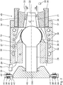
- Fig. 2 shows details of the tool head 14 in an axial longitudinal section.
- the tool head 14 has a head housing 19, in which a material or mass flow path 20 is predetermined, the outlet nozzle side opens into an extrusion annular channel 21.
- the extrusion annular channel 21 is bounded on the inside by a tool mandrel 22 and is limited to the outside by a tool ring 23.
- a longitudinal axis LE of the extruder 2 can be a longitudinal axis LWK of the tool head 14 in alignment, parallel or, as in the described embodiment, perpendicular thereto.
- the longitudinal axis LWK of the tool head 14 thus extends radially to the longitudinal axis LE of the extruder 2.
- a material inlet 24 of the extruder 2 thus extends through a jacket wall 25 of the head housing 19, as in the Fig. 2 indicated schematically.
- This material inlet 24 forms an inlet channel which is in fluid communication with the extrusion annular channel 21 via a distribution channel 26 and the material flow path 20.
- the tool mandrel 22 is supported and held by a housing-side mandrel carrier 27.
- the mandrel carrier 27 has a dome-shaped mandrel-joint portion 28 and a tilt rod portion 29.
- a centering device 30 is arranged, which will be even closer is explained.
- the mandrel carrier 27 is tiltably mounted relative to the tool ring 23 by two degrees of freedom via a tilting joint.
- the tilting joint is formed on the one hand by the mandrel-joint portion 28 as a dome part and a complementary thereto designed cup portion 31 of a manifold body 32, as a pan part.
- the distributor body 32 is mounted in the housing housing 19 fixed to the housing.
- the tilting joint 28, 31 is designed as a ball joint. Between the two joint parts of the ball joint 28, 31, so the mandrel joint portion 28 and the manifold pan portion 31, a predetermined component game, for example, be performed in the range between 50 microns and 200 microns.
- the dome part of the ball joint 28, 31 thus the mandrel joint portion may be integrally formed on the tilt rod portion 29 of the mandrel support 27.
- the tilting joint 28, 31 can be hardened Have surfaces on the mandrel hinge portion 28 and / or on the distributor pan portion 31. These may be surfaces treated with powder metallurgy.
- the sections 28, 31 of the tilting joint may have a sliding coating.
- the tiltability of the mandrel carrier 27 relative to the tool ring 23 via the tilting joint 28, 31 is such that depending on the tilt position of the mandrel carrier 27, a circumferential distribution of a width RK of the extrusion annular channel 21 between a nozzle-side portion of the tool mandrel 22 and the tool ring 23 can be predetermined.
- a circumferential distribution of a width RK of the extrusion annular channel 21 between a nozzle-side portion of the tool mandrel 22 and the tool ring 23 can be predetermined.
- a predetermined distribution of the width RK of the extrusion ring channel 21 in the circumferential direction about the longitudinal axis LWK of the tool head 14. This is a homogenization of a hose wall thickness of one extruded with the extruder 2 Hose in the circumferential direction possible.
- a displacement of the tool ring 23 is not required.
- the material flow path 20 between the material inlet 24 and the extrusion annular channel 21 can follow a heart curve.
- the expert finds for example in the textbook “ Handbuch Urformen - Edition Handbuch der Vietnamesestechnik "(second edition, 2003, Carl Hanser Verlag, publisher Bührig-Polaczek et al.).
- Cooling fluid can generally be a tempering fluid for tempering the tool head 14, ie for holding the tool head 14 at a predetermined temperature.
- the tool mandrel 22 and / or the tool ring 23 can be designed as replacement parts.
- different pairings of one type each of the tool mandrel 22 and one type of tool ring 23 can be predeterminable.
- the scope of delivery of the tool head 14 may accordingly include a set of several such pairings of tool mandrel / tool ring.
- the tool mandrel 22 may be releasably connected to the mandrel carrier 27, for example via a screw connection.
- the tool ring 23 may be held against an extrusion direction ER by an axial adjustment housing body 35.
- the latter can be screwed by a thread 36 with an adjusting portion 37 of the head housing 19.
- the axial adjustment housing body 35 may be designed as a centering nut.
- the setting section 37 represents a receptacle for the axial adjustment housing body 35.
- a specification of an axial position of the axial adjustment housing body 35 relative to the head housing 19 makes it possible to specify an axial position of the tool ring 23 relative to the tool mandrel 22.
- the tool ring 23 is floatingly received in the axial adjustment housing body 35.
- This specification of the axial position, in conjunction with a conical shaping of the tool mandrel 22 and / or the tool ring 23 in the region of the extrusion ring channel 21, enables setting of a width RK average of the circumference of the extrusion ring channel 21 Extrusion annular channel 21.
- axial position of the tool ring 23 relative to the tool mandrel 22 can thus specify a wall thickness of the tube to be extruded.
- the centering device 30 has a plurality of centering actuators in the form of centering screws 38, of which in the FIG. 2 schematically two centering 38 are shown.
- the centering screws 38 extend radially to the longitudinal axis LWK of the tool head 14 and thus to a good approximation also radially to the longitudinal axis of the mandrel carrier 27.
- the centering screws 38 are mounted on the head housing 19 in a manner not shown.
- the centering screws 38 may be screwed into ring portions 39 of an otherwise not shown centering ring, which in turn is mounted on the head housing 19 and / or on the manifold body 32.
- An internal thread of the ring portion 39 may also be part of a separate from the head housing 19 and firmly connected with this centering, which in the Fig. 2 indicated at 40.
- Free ends 41 of the centering screws 38 abut against a peripheral wall 42 of a centering head 43 of the mandrel carrier 27.
- the centering head 43 is fixedly connected to the tilting rod portion 29 of the mandrel carrier 27 and may be an integral part of the tilting rod portion 29.
- the respective tilt position ie the position of the longitudinal axis of the mandrel carrier 27 to the longitudinal axis of the entire tool head 14, are specified. It can, for example, three or more centering 38 on the type of in the Fig.
- the centering screws 38 can be driven by means of corresponding, respectively associated rotary actuators 44 motor.
- a tool head assembly 45 which is part of the tool head 14, may additionally include at least one sensor 46 for measuring a wall thickness of the extruded with the tool head hose.
- the wall thickness sensor 46 can be designed as a radiometric sensor, for example as an X-ray sensor. Both the rotary actuators 44, which then represent actuators of the centering device 30, and the at least one wall thickness sensor 46 are in signal communication with the controller 11 and the control unit 13 (see also Fig. 3 ).
- An adjustment of the average width of the extrusion ring channel 21 can in particular be made steplessly with an accuracy in the range of 1/100 millimeter.
- THz waves can also take place.
- a wall thickness of a tube to be extruded can be set to a predetermined value with a tolerance that is less than 100 microns, which may be less than 50 microns, which may be less than 30 microns, which may be less than 20 microns and also may be less than 10 microns.
- thermosensors In variants of the extrusion plant 1, it is also possible to use a plurality of feed pressure sensors and / or a plurality of feed temperature sensors and / or a plurality of tool head pressure sensors and / or a plurality of discharge temperature sensors.
- Various temperature sensors can be arranged in particular in different temperature zones of the extruder 2.
- a temperature in the at least one temperature zone in the conveying path of the extrudate mass of the extrusion plant 1 can be predetermined via a temperature control medium.
- a temperature control medium for example water, and in particular cooled.
- Another controlled variable which can be kept constant by comparing a measured actual value with a predetermined desired value via the control unit 13, is a material throughput in the conveying path of the extrusion plant 1. This throughput can be measured at different points of the entire conveying path between the charging device 3 and the tool head 14 become.
- the mass to be extruded is first introduced into the charging device 3. Subsequently, the mass to be extruded is conveyed through the charging device 3 and the extruder 2. The extrudate produced is then discharged from the extruder 2 in profile or tubular form via the tool head 14.
- These control signals of the control unit 13 can on the hopper rotational drive ADA and / or on the screw rotary drive BDA and / or on the extruder drive unit 16 and / or on actuating components of the tool head 24, for example, the actuators 44 of the centering device 30 act.
- a rotational speed of the feed hopper 5 a rotational speed of the feed screw and / or a screw speed of the extruder 2 can be predetermined or manipulated variables of adjustable components of the tool head 24, such as the circumferential distribution and / or the mean value of the width RK of the extrusion, can be selected -Ringkanals 21 pretend.
- Drives of the extrusion system 1, especially the rotary actuators 10, 15, 44 and the extrusion drive 16, can be designed to be infinitely variable.
- a tilt position specification in the region of the centering head 43 can also be effected via linearly displaceable reciprocating pistons.
- Drives of the centering device can be designed as electric motors or hydraulic cylinders.
- a cooling of the tool head 14 can be controlled or regulated and, in particular, depending on the material throughput, a Shore hardness of the material and depending on the respective design of the material flow path 20 on the one hand in the region of the manifold body 32 and on the other hand in the region of the nozzle-side outlet in the extrusion annular channel.
Landscapes
- Engineering & Computer Science (AREA)
- Mechanical Engineering (AREA)
- Manufacturing & Machinery (AREA)
- Extrusion Moulding Of Plastics Or The Like (AREA)
Abstract
Ein Werkzeugkopf (14) ist Bestandteil eines Hohlprofil-Extruders. Der Werkzeugkopf (14) hat ein Kopfgehäuse (19). Ein Extrusions-Ringkanal (21) ist nach innen begrenzt durch einen Werkzeugdorn (22) und außen durch einen Werkzeugring (23). Der Werkzeugdorn (22) wird von einem gehäuseseitigen Dornträger (27) getragen und gehalten. Der Dornträger (27) ist über ein Kippgelenk (28, 31) relativ zum Werkzeugring (23) um zwei Freiheitsgrade kippbar gelagert. Abhängig von der Kippstellung des Dornträgers (27) ist eine Umgangsverteilung einer Weite des Extrusions-Ringkanals (21) vorgebbar. Eine Zentriereinrichtung (30) dient zur Vorgabe der Kippstellung des Dornträgers (27). Es resultiert ein Werkzeugkopf, bei dem die Vorgabe einer Hohlprofil-Wanddicke in für eine Massenherstellung handhabbarer Form gewährleisten werden kann.A tool head (14) is part of a hollow profile extruder. The tool head (14) has a head housing (19). An extrusion ring channel (21) is delimited on the inside by a tool mandrel (22) and on the outside by a tool ring (23). The tool mandrel (22) is carried and held by a mandrel carrier (27) on the housing side. The mandrel carrier (27) is mounted such that it can be tilted by two degrees of freedom relative to the tool ring (23) via a tilt joint (28, 31). Depending on the tilt position of the mandrel carrier (27), a circumferential distribution of a width of the extrusion ring channel (21) can be specified. A centering device (30) serves to specify the tilt position of the mandrel carrier (27). The result is a tool head in which the specification of a hollow profile wall thickness in a form that can be handled for mass production can be ensured.
Description
Die vorliegende Patentanmeldung nimmt die Priorität der deutschen Patentanmeldung
Die Erfindung betrifft einen Werkzeugkopf für einen Hohlprofil-Extruder, insbesondere für einen Schlauch-Extruder. Ferner betrifft die Erfindung eine Wekzeugkopf-Baugruppe mit einem derartigen Werkzeugkopf, einen Extruder mit einem derartigen Werkzeugkopf oder einer derartigen Werkzeugkopf-Baugruppe sowie eine Extrusionsanlage mit einem derartigen Extruder.The invention relates to a tool head for a hollow-section extruder, in particular for a hose extruder. Furthermore, the invention relates to a tool head assembly with such a tool head, an extruder with such a tool head or such a tool head assembly and an extrusion line with such an extruder.
Ein Silikonextruder ist bekannt aus der
Es ist eine Aufgabe der vorliegenden Erfindung, einen Werkzeugkopf für einen Hohlprofil-Extruder, insbesondere für einen Schlauch-Extruder, derart weiterzubilden, dass die Vorgabe einer Schlauch-Wanddicke in für eine Massenherstellung handhabbarer Form gewährleistet werden kann.It is an object of the present invention to develop a tool head for a hollow-section extruder, in particular for a hose extruder, in such a way that it is possible to ensure the specification of a hose wall thickness in a form that can be handled in a mass production.
Diese Aufgabe ist erfindungsgemäß gelöst durch einen Werkzeugkopf mit den im Anspruch 1 angegebenen Merkmalen.This object is achieved by a tool head with the features specified in claim 1.
Erfindungsgemäß wird eine Vorgabe einer Umfangsverteilung einer Weite des Extrusions-Ringkanals, die einer Umfangsverteilung einer zu extrudierenden Hohlprofil-Stärke, insbesondere einer Schlauchstärke, entspricht, über eine vorgebbare Verkippung des Werkzeugdorns relativ zum Werkzeugring erreicht. Eine Relativposition einer zu extrudierenden Hohlprofil- bzw. Schlauch-Mantelwand, die vorgegeben wird durch die Außenbegrenzung des Extrusions-Ringkanals, also durch die Lage des Werkzeugrings, bleibt unabhängig von der Werkzeugdorn-Kippstellung. Zur Einstellung der Umfangsverteilung der Weite des Extrusions-Ringkanals ist also keine Verlagerung des Werkzeugrings relativ zum Gehäuse erforderlich. Es resultiert eine definierte Lage einer Mantelwand des zu extrudierenden Hohlprofils bzw. Schlauchs unmittelbar nach dem Werkzeugkopf, was für eine nachfolgende Führung beziehungsweise Erfassung des zu extrudierenden Schlauchs insbesondere benachbart zum Werkzeugkopf von Vorteil ist. Hierdurch kann beispielsweise eine sensorische Erfassung von Parametern des Hohlprofils, insbesondere von Parametern des Schlauchs, vereinfacht und/oder verbessert werden. Der Extrusions-Ringkanal kann einer Herzkurve folgen. Ein in den Extrusions-Ringkanal einmündender Materialfließweg für zu extrudierendes Material kann in einem Verteilerkörper ausgebildet sein, der im Kopfgehäuse des Werkzeugkopfes montiert ist. Im Kopfgehäuse kann mindestens ein Kühlkanal zum Kühlen des Werkzeugkopfes angeordnet sein. Das Kippgelenk, über welches der Dornträger relativ zum Werkzeugring kippbar ist, kann gehärtete Oberflächen aufweisen. Das Kippgelenk kann pulvermetallurgisch behandelte Oberflächen aufweisen. Mindestens eine der Oberflächen des Kippgelenks kann eine Gleitbeschichtung aufweisen. Der Werkzeugdorn und/oder der Werkzeugring können als Tauschteile ausgeführt sein. Zur Ausstattung des Werkzeugkopfes kann ein Set mit verschiedenen Paarungen aus jeweils einem Werkzeugdorn und jeweils einem Werkzeugring oder auch ein Set mit jeweils mehreren Werkzeugdornen/Werkzeugringen, die auf einen Werkzeugring/Werkzeugdorn abgestimmt sind, beinhalten.According to the invention, a specification of a circumferential distribution of a width of the extrusion annular channel, which corresponds to a circumferential distribution of a hollow profile thickness to be extruded, in particular a tube thickness, is achieved by means of a predefinable tilting of the tool mandrel relative to the tool ring. A relative position of a hollow section to be extruded or hose jacket wall, which is specified by the outer boundary of the extrusion ring channel, ie by the position of the tool ring, remains independent of the tool mandrel tilt position. To adjust the circumferential distribution of the width of the extrusion ring channel so no displacement of the tool ring relative to the housing is required. This results in a defined position of a jacket wall of the hollow profile or hose to be extruded immediately after the tool head, which is advantageous for subsequent guidance or detection of the hose to be extruded, in particular adjacent to the tool head. In this way, for example, a sensory detection of parameters of the hollow profile, in particular of parameters of the hose, can be simplified and / or improved. The extrusion annulus may follow a heart curve. A material flow path for the material to be extruded, which opens into the extrusion ring channel, can be formed in a distributor body which is mounted in the head housing of the tool head. At least one cooling channel for cooling the tool head can be arranged in the head housing. The tilting joint, over which the mandrel carrier is tiltable relative to the tool ring, may have hardened surfaces. The tilting joint may have powder metallurgy treated surfaces. At least one of the surfaces of the tilting joint may have a lubricious coating. The tool mandrel and / or the tool ring can be designed as replacement parts. To equip the tool head, a set with different pairings of a respective tool mandrel and a respective tool ring or a set with a plurality of tool mandrels / tool rings, which are adapted to a tool ring / tool mandrel include.
Eine Halterung des Werkzeugrings vom Axial-Einstell-Gehäusekörper entgegen der Kraftrichtung des Extrusionsdrucks ermöglicht es beispielsweise, über eine Vorgabe einer Axialstellung des Axial-Einstell-Gehäusekörpers eine Axialposition des Werkzeugrings zum Werkzeugdorn vorzugeben. Eine derartige Axialstellungsvorgabe ermöglicht eine Einstellung einer über den Umfang gemittelten Weite des Extrusions-Ringkanals. Der Axial-Einstell-Gehäusekörper kann als Zentriermutter ausgeführt sein. Der Axial-Einstell-Gehäusekörper kann in einer Aufnahme montiert sein, die wiederum am Gehäuse montiert ist.A holder of the tool ring from the axial adjustment housing body against the direction of the force of the extrusion pressure makes it possible, for example, via a specification of an axial position of the axial adjustment housing body to specify an axial position of the tool ring to the tool mandrel. Such Axialstellungsvorgabe allows adjustment of averaged over the circumference of the width of the extrusion annular channel. The axial adjustment housing body may be designed as a centering nut. The axial adjustment housing body may be mounted in a receptacle which in turn is mounted to the housing.
Eine Ausgestaltung nach Anspruch 2 nutzt eine Hebelwirkung des Dornträgers zur Verkippung des Werkzeugdorns. Ein Abstand der Zentriereinrichtung zum Kippgelenk kann dabei größer sein als ein Abstand zwischen dem Kippgelenk und einem Düsenauslass des Extrusions-Ringkanals. Dieser Abstand kann beispielsweise mehr als das 1, 1-fache , mehr als das 1,2-fache, mehr als das 1,25-fache, mehr als das 1,5-fache, mehr als das 2-fache, mehr als das 3-fache oder auch mehr als das 5-fache des Abstandes zwischen dem Kippgelenk und der Düsenöffnung betragen.An embodiment according to
Zentrier-Stellglieder nach Anspruch 3 haben sich zum Einstellen einer Kippposition des Werkzeugdorns bewährt. Die Zentrier-Stellglieder können als Zentrierschrauben ausgeführt sein. Die Zentriereinrichtung kann von einem Zentrierring getragen werden, der seinerseits am Kopfgehäuse montiert ist. Der Zentrierring kann am Verteilerkörper montiert sein. Ein gehäuseseitiges Innengewinde, welches komplementär zum jeweiligen Zentrier-Stellglied ausgeführt ist, kann Bestandteil einer mit dem Kopfgehäuse fest verbundenen Zentrierbuchse sein.Centering actuators according to
Ein Kugelgelenk nach Anspruch 4 hat sich als Kippgelenk zur stufenlosen Vorgabe der Kippstellung des Werkzeugdorns relativ zum Werkzeugring bewährt. Das Kugelgelenk kann mit einer vorgegebenen Toleranz zwischen den Gelenkteilen, also einem Gelenkkopf beziehungsweise einem Kalottenteil und einer Gelenkpfanne beziehungsweise einem Pfannenteil, ausgeführt sein.A ball joint according to claim 4 has proven to be a tilting joint for stepless specification of the tilt position of the tool mandrel relative to the tool ring. The ball joint can with a given tolerance between the joint parts, ie a joint head or a dome part and a joint socket or a socket part, be executed.
Eine Ausgestaltung nach Anspruch 5 hat sich insbesondere aus Stabilitätsgründen bewährt. Ein Pfannenteil des Kugelgelenks kann gehäuseseitig angeordnet sein. Das Pfannenteil kann in einem im Gehäuse montierten Verteilerkörper und/oder in einem Zentrierring der Zentriereinrichtung oder auch direkt im Kopfgehäuse ausgeführt sein.An embodiment according to
Eine Halterung des Werkzeugrings nach Anspruch 6 vermeidet unerwünschte Belastungsspitzen bei der Übertragung des Extrusionsdrucks vom Werkzeugring auf den Axial-Einstell-Gehäusekörper.A holder of the tool ring according to
Die Vorteile einer Werkzeug-Baugruppe nach Anspruch 7 entsprechen denen, die vorstehend unter Bezugnahme auf den Werkzeugkopf bereits erläutert wurden. Aufgrund der Steuer-/Regeleinrichtung ist es möglich, mit der Werkzeugkopf-Baugruppe bestimmte Parameter des zu extrudierenden Schlauches gesteuert oder geregelt innerhalb vorgegebener Toleranzgrenzen zu halten. Insbesondere eine Closed-Loop-Steuerung kann realisiert werden. Der mindestens eine Aktor der Zentriereinrichtung kann in Form einer oder mehrerer motorisch angetriebener Zentrierschrauben realisiert sein. Der mindestens eine Aktor kann als Schrittmotor ausgeführt sein. Der mindestens eine Aktor kann mit einem Planetengetriebe zusammenwirken. Alternativ oder zusätzlich zur Signalverbindung mit mindestens einem Aktor der Zentriereinrichtung kann die Steuer-Regeleinrichtung auch mit einem Aktor zusammenwirken, der auf den Axial-Einstell-Gehäusekörper zur Verstellung von diesem wirkt. Dies gilt insbesondere dann, wenn der Axial-Einstell-Gehäusekörper als Zentriermutter ausgeführt ist. Der Aktor kann dann eine Verdrehung der Zentriermutter herbeiführen. Auch in dieem Fall kann der Aktor als Schrittmotor ausgeführt sein und kann über ein Planetengetriebe auf die Zentriermutter wirken.The advantages of a tool assembly according to claim 7 correspond to those which have already been explained above with reference to the tool head. Due to the control / regulating device, it is possible with the tool head assembly controlled certain parameters of the tube to be extruded or controlled to keep within predetermined tolerance limits. In particular, a closed-loop control can be realized. The at least one actuator of the centering device can be realized in the form of one or more motor-driven centering screws. The at least one actuator can be designed as a stepper motor. The at least one actuator can interact with a planetary gear. Alternatively or in addition to the signal connection with at least one actuator of the centering device, the control device can also cooperate with an actuator which acts on the axial adjustment housing body for the adjustment of this. This is especially true when the axial adjustment housing body is designed as centering. The actor can then cause a rotation of the centering nut. In this case too, the actuator can be designed as a stepping motor and can act on the centering nut via a planetary gear.
Bei dem Sensor kann es sich um einen Sensor zum Messen einer Wandstärke des mit dem Werkzeugkopfs extrudierten Schlauchs handeln. Der Sensor kann als radiometrischer Sensor, zum Beispiel als Röntgensensor ausgeführt sein. Alternativ oder zusätzlich kann der Sensor als Mikrowellen- oder als Ultraschallsensor ausgeführt sein. Die Steuer-/Regeleinrichtung kann zusätzlich eine Mehrzahl weiterer Eingangsgrößen des Extruders und/oder der Extrusionsanlage erfassen und zur Steuerung und/oder Regelung entsprechender Parameter Stellsignale an Antriebseinheiten beziehungsweise Aktoren des Extruders und der Extrusionsanlage weitergeben. Hierbei hat sich insbesondere die Beibehaltung eines konstanten Beschickungsdrucks als für das Extrusionsergebnis besonders vorteilhaft herausgestellt. Bei den Eingangsgrößen kann es sich um eine Ist-Beschickungstemperatur des Extrusionsmaterials oder auch um einen Austragsdruck der extrudierten Masse im Bereich des Werkzeugkopfes oder auch um eine Austrags-Temperatur handeln.The sensor may be a sensor for measuring a wall thickness of the tube extruded with the tool head. The sensor can be designed as a radiometric sensor, for example as an X-ray sensor. Alternatively or additionally, the sensor may be designed as a microwave or as an ultrasonic sensor. The control / regulating device can additionally detect a plurality of further input variables of the extruder and / or the extrusion plant and pass control signals to drive units or actuators of the extruder and the extrusion plant for controlling and / or regulating corresponding parameters. In particular, the maintenance of a constant feed pressure has proven particularly advantageous for the extrusion result. The input variables may be an actual feed temperature of the extrusion material or else a discharge pressure of the extruded mass in the region of the tool head or else a discharge temperature.
Die Vorteile eines Extruders nach Anspruch 8 sowie einer Extrusionsanlage nach Anspruch 9 entsprechen denen, die vorstehend unter Bezugnahme auf den Werkzeugkopf und die Werkzeugkopf-Baugruppe bereits erläutert wurden.The advantages of an extruder according to
Bei der Beschickungsvorrichtung der Extrusionsanlage kann es sich um eine Beschickungsvorrichtung mit einer Beschickungsschnecke und einem Aufgabetrichter handeln. Alternativ kann die Beschickungsvorrichtung gemäß diesem weiteren Aspekt auch anders aufgebaut sein.The feeder of the extrusion plant may be a feeder with a feed screw and a hopper. Alternatively, the charging device according to this further aspect may also be constructed differently.
Bei dem Extruder kann es sich um einen Silikonextruder und/oder um einen Extruder für ein thermoplastisches Material bzw. für ein Polyolefin-Material handeln. Ein extrudiertes Hohlprofil bzw. ein extrudierter Schlauch kann insbesondere in der Medizintechnik zum Einsatz kommen.The extruder may be a silicone extruder and / or an extruder for a thermoplastic material or for a polyolefin material. An extruded hollow profile or an extruded tube can be used in particular in medical technology.
Ein Ausführungsbeispiel der Erfindung wird nachfolgend anhand der Zeichnung näher erläutert. In dieser zeigen:
- Fig. 1
- eine perspektivische Ansicht einer Extrusionsanlage mit einem Extruder und einer Beschickungsvorrichtung in einer Beschickungsstellung zum Beschicken des Extruders mit zu extrudierender Masse;
- Fig. 2
- schematisch einen Schnitt durch einen Wekzeugkopf des Extruders der Extrusionsanlage nach
Figur 1 ; - Fig. 3
- ein Signalverarbeitungsschema bei einem geregelten Betrieb der Extrusionsanlage.
- Fig. 1
- a perspective view of an extrusion plant with an extruder and a feeder in a feed position for feeding the extruder to be extruded mass;
- Fig. 2
- schematically a section through a tool head of the extruder of the extrusion plant according to
FIG. 1 ; - Fig. 3
- a signal processing scheme in a controlled operation of the extrusion plant.
Eine Extrusionsanlage 1 hat einen Extruder 2 und eine Beschickungsvorrichtung 3 zum Beschicken des Extruders 2 mit zu extrudierender Masse. Bei der zu extrudierenden Masse kann es sich um Silikon handeln. Bei der zu extrudierenden Masse kann es sich auch um ein anderes Material handeln beispielsweise um einen Thermoplasten. Der Extruder 2 ist als Hohlprofil-Extruder und im dargestellten Ausführungsbeispiel als Schlauch-Extruder ausgeführt. Die Beschickungsvorrichtung 3 hat oben einen Aufgabekasten 4, der bodenseitig in einen Aufgabetrichter 5 mündet. Letzterer mündet wiederum in eine bodenseitige Beschickungsöffnung 6. Die Massen-Beschickungsöffnung 6 steht über einem Beschickungskanal 7 mit einer Einzugszone des Extruders 2 in Fluidverbindung.An extrusion plant 1 has an
Die
Der Extruder 2 kann als Einschnecken- oder auch als Doppelschneckenextruder ausgeführt sein.The
Teil der Beschickungsvorrichtung 3 ist eine nicht näher dargestellte Beschickungsschnecke. Letztere ist axial und radial an einem Rahmengehäuse 8 der Extrusionsanlage 1 gelagert.Part of the
Der Aufgabetrichter 5 ist drehantreibbar ausgeführt. Nahe der Beschickungsöffnung 6 ist der Aufgabetrichter 5 wiederum axial und radial relativ zum Rahmengehäuse 8 gelagert.The
Die beiden Drehantriebe für die Beschickungsschnecke einerseits und den Aufgabetrichter 5 andererseits sind voneinander unabhängig ausgeführt. Bei einer alternativen Ausführung der Extrusionsanlage 1 kann auch genau ein gemeinsamer Antrieb für die Beschickungsschnecke einerseits und den Aufgabetrichter 5 andererseits vorhanden sein, wobei ein vorgegebenes Drehzahlverhältnis zwischen einer Beschickungsschneckendrehzahl einerseits und einer Aufgabetrichterdrehzahl andererseits über ein Über- bzw. Untersetzungsgetriebe eines solchen gemeinsamen Antriebs vorgebbar ist. Die Drehantriebe oder der gemeinsame Antrieb für die Beschickungsschnecke und den Aufgabetrichter 5 können als Synchronmotor ausgeführt sein.The two rotary drives for the feed screw on the one hand and the
Die Beschickungsvorrichtung 3 wird mit Kühlwasser gekühlt, welches in einem Kreislauf geführt sein kann.The charging
Die
Die Beschickungsvorrichtung 3 kann in eine relativ zur Beschickungsstellung der
Zur Vorbereitung des Ausschwenkens der Beschickungsvorrichtung 3 in die Reinigungs- bzw. Wartungsstellung wird eine Flanschverbindung 10, zwischen zwei Abschnitten des Beschickungskanals 7 gelöst.To prepare the swiveling out of the
Die Extrusionsanlage 1 hat eine zentrale Steuerung 11 mit einem Bedienungsterminal 12. Die Steuerung 11 steht mit den beiden Drehantrieben der Beschickungsschnecke und des Aufgabetrichters 5 in Signalverbindung.The extrusion plant 1 has a
In einem Übergangsbereich zwischen der Beschickungsvorrichtung 3 und dem Extruder 2, also im Bereich des Beschickungskanals 7, ist ein Beschickungs-Drucksensor BDS (vgl.
Teil der Steuerung 11 ist eine in der
Im Beschichtungskanal 7 ist weiterhin ein Beschickungs-Temperatursensor BTS zum Messen einer Ist-Beschickungstemperatur der zu extrudierenden Masse angeordnet. Der Beschickungs-Temperatursensor BTS steht mit der Regeleinheit 13 in Signalverbindung.In the coating channel 7, a feed temperature sensor BTS for measuring an actual feed temperature of the mass to be extruded is further arranged. The charging temperature sensor BTS is in signal communication with the
Weiterhin hat die Extrusionsanlage 1 in einem Werkzeugkopf 14 des Extruders 2, der in der
Die Extrusionsanlage 1 hat weiterhin einen Austrags-Temperatursensor 18, der ebenfalls im Werkzeugkopf 14 des Extruders 2 angeordnet ist. Der Austrags-Temperatursensor 18 dient zum Messen einer Ist-Austragstemperatur der zu extrudierenden Masse. Der Austrags-Temperatursensor 18 steht mit der Regeleinheit 13 in Signalverbindung.The extrusion system 1 furthermore has a
Der Werkzeugkopf 14 hat ein Kopfgehäuse 19, in dem ein Material- beziehungsweise Massenfließweg 20 vorgegeben ist, der austrittsdüsenseitig in einen Extrusions-Ringkanal 21 ausmündet.The
Der Extrusions-Ringkanal 21 ist nach innen begrenzt durch einen Werkzeugdorn 22 und ist nach außen begrenzt durch einen Werkzeugring 23. Hin zu einer Austrittsdüse des Werkzeugkopfes 14 sind der Werkzeugdorn 22 und der Werkzeugring 23 nicht vollständig, sondern abgebrochen dargestellt. Im Vergleich zu einer Längsachse LE des Extruders 2 (vgl.
Dieser Materialeinlauf 24 bildet einen Einlass-Kanal, der mit dem Extrusions-Ringkanal 21 über einen Verteilerkanal 26 und den Materialfließweg 20 in Fluidverbindung steht.This
Der Werkzeugdorn 22 wird von einem gehäuseseitigen Dornträger 27 getragen und gehalten. Der Dornträger 27 hat einen kalottenförmigen Dorn-Gelenkabschnitt 28 und einen Kippstangenabschnitt 29. An einem freien Ende des Kippstangenabschnitts 29 des Dornträgers 27, welches von einer Dornseite des Dornträgers 27 mit dem Werkzeugdorn 22 abgewandt ist, ist eine Zentriereinrichtung 30 angeordnet, die nachfolgend noch näher erläutert wird.The
Der Dornträger 27 ist über ein Kippgelenk relativ zum Werkzeugring 23 um zwei Freiheitsgrade kippbar gelagert. Das Kippgelenk wird gebildet einerseits durch den Dorn-Gelenkabschnitt 28 als Kalottenteil und einen komplementär hierzu ausgeführten Pfannenabschnitt 31 eines Verteilerkörpers 32, als Pfannenteil. Der Verteilerkörper 32 ist im Kopfgehäuse 19 gehäusefest montiert ist.The
Das Kippgelenk 28, 31 ist als Kugelgelenk ausgeführt. Zwischen den beiden Gelenkteilen des Kugelgelenks 28, 31, also dem Dorn-Gelenkabschnitt 28 und dem Verteiler-Pfannenabschnitt 31, kann ein vorgegebenes Bauteil-Spiel, beispielsweise im Bereich zwischen 50 µm und 200 µm ausgeführt sein. Das Kalottenteil des Kugelgelenks 28, 31 also der Dorn-Gelenkabschnitt, kann einstückig an den Kippstangenabschnitt 29 des Dornträgers 27 angeformt sein. Das Kippgelenk 28, 31 kann gehärtete Oberflächen am Dorn-Gelenkabschnitt 28 und/oder am Verteiler-Pfannenabschnitt 31 aufweisen. Hierbei kann es sich um pulvermetallurgisch behandelte Oberflächen handeln. Die Abschnitte 28, 31 des Kippgelenks können eine Gleitbeschichtung aufweisen.The tilting joint 28, 31 is designed as a ball joint. Between the two joint parts of the ball joint 28, 31, so the mandrel
Die Kippbarkeit des Dornträgers 27 relativ zum Werkzeugring 23 über das Kippgelenk 28, 31 ist derart, dass abhängig von der Kippstellung des Dornträgers 27 eine Umfangsverteilung einer Weite RK des Extrusions-Ringkanals 21 zwischen einem düsenseitigen Abschnitts des Werkzeugdorns 22 und dem Werkzeugring 23 vorgebbar ist. Je nach Kippung des Werkzeugdorns 22 über das Kippgelenk 28, 31 ergibt sich also eine vorgebbare Verteilung der Weite RK des Extrusions-Ringkanals 21 in Umfangsrichtung um die Längsachse LWK des Werkzeugkopfes 14. Hierüber ist eine Homogenisierung einer Schlauch-Wanddicke eines mit dem Extruder 2 extrudierten Schlauchs in Umfangsrichtung möglich. Eine Relativposition einer Schlauch-Mantelwand 33, die in der
Der Materialfließweg 20 zwischen dem Materialeinlauf 24 und dem Extrusions-Ringkanal 21 kann einer Herzkurve folgen. Eine Beschreibung hierzu findet der Fachmann beispielsweise in dem Fachbuch "
Im Kopfgehäuse 19 sind mehrere Kühlkanäle 34 ausgeführt, über die ein Kühlfluid zum Kühlen des Werkzeugkopfes 14 fließen kann. Bei dem Kühlfluid kann es sich allgemein um ein Temperierfluid zum Temperieren des Werkzeugkopfes 14, also zum Halten des Werkzeugkopfes 14 auf einer vorgegebenen Temperatur handeln.In the head housing 19 a plurality of
Der Werkzeugdorn 22 und/oder der Werkzeugring 23 können als Tauschteile ausgeführt sein. Insbesondere können verschiedene Paarungen aus je einem Typ des Werkzeugdorns 22 und einem Typ des Werkzeugring 23 vorgebbar sein. Zum Lieferumfang des Werkzeugkopfes 14 kann entsprechend ein Set aus mehreren derartigen Paarungen Werkzeugdorn/Werkzeugring gehören.The
Der Werkzeugdorn 22 kann lösbar mit dem Dornträger 27, beispielsweise über eine Schraubverbindung, verbunden sein. Der Werkzeugring 23 kann entgegen einer Extrusionsrichtung ER von einem Axial-Einstell-Gehäusekörper 35 gehalten sein. Letzterer kann über ein Gewinde 36 mit einem Einstellabschnitt 37 des Kopfgehäuses 19 verschraubt sein. Der Axial-Einstell-Gehäusekörper 35 kann als Zentriermutter ausgeführt sein. Der Einstellabschnitt 37 stellt eine Aufnahme für den Axial-Einstell-Gehäusekörper 35 dar. Über eine Vorgabe einer Axialposition des Axial-Einstell-Gehäusekörpers 35 relativ zum Kopfgehäuse 19 vorgebbar ist damit eine axiale Position des Werkzeugrings 23 zum Werkzeugdorn 22.The
Der Werkzeugring 23 ist schwimmend im Axial-Einstell-Gehäusekörper 35 aufgenommen.The
Diese Vorgabe der Axialposition ermöglicht in Verbindung mit einer konischen Formgebung des Werkzeugdorns 22 und/oder des Werkzeugrings 23 im Bereich des Extrusions-Ringkanals 21 die Einstellung einer über den Umfang des Extrusions-Ringkanals 21 gemittelten Weite RKMittel des Extrusions-Ringkanals 21. Über die mittels des Axial-Einstell-Gehäusekörpers 35 vorgebbare Axialposition des Werkzeugrings 23 relativ zum Werkzeugdorn 22 lässt sich somit eine Wandstärke des zu extrudierenden Schlauchs vorgeben.This specification of the axial position, in conjunction with a conical shaping of the
Die Zentriereinrichtung 30 hat eine Mehrzahl von Zentrier-Stellgliedern in Form von Zentrierschrauben 38, von denen in der
Freie Enden 41 der Zentrierschrauben 38 liegen an einer Umfangswand 42 eines Zentrierkopfes 43 des Dornträgers 27 an. Der Zentrierkopf 43 ist fest mit dem Kippstangenabschnitt 29 des Dornträgers 27 verbunden und kann ein integraler Bestandteil des Kippstangenabschnitts 29 sein. Über eine Einschraubtiefe der Zentrierschrauben 38 in den jeweiligen Zentrierbuchsen 40 kann die jeweilige Kippstellung, also die Lage der Längsachse des Dornträgers 27 zur Längsachse des gesamten Werkzeugkopfes 14, vorgegeben werden. Es können beispielsweise drei oder noch mehr Zentrierschrauben 38 nach Art der in der
Die Zentrierschrauben 38 können mithilfe entsprechender, jeweils zugeordneter Drehantriebe 44 motorisch angetrieben sein.The centering screws 38 can be driven by means of corresponding, respectively associated
Zu einer Werkzeugkopf-Baugruppe 45, deren Bestandteil der Werkzeugkopf 14 ist, kann zusätzlich noch mindestens ein Sensor 46 zum Messen einer Wandstärke des mit dem Werkzeugkopf extrudierten Schlauchs gehören. Der Wandstärken-Sensor 46 kann als radiometrischer Sensor, zum Beispiel als Röntgensensor ausgeführt sein. Sowohl die Drehantriebe 44, die dann Aktoren der Zentriereinrichtung 30 darstellen, als auch der mindestens eine Wandstärken-Sensor 46 stehen mit der Steuerung 11 und der Regeleinheit 13 in Signalverbindung (vgl. auch
Eine Einstellung der mittleren Weite des Extrusions-Ringkanals 21 kann insbesondere stufenlos mit einer Genauigkeit im Bereich von 1/100 Millimeter erfolgen.An adjustment of the average width of the
Anstelle eines Röntgensensors kann auch eine sensorische Erfassung über THz-Wellen erfolgen.Instead of an X-ray sensor, a sensory detection via THz waves can also take place.
Eine Wandstärke eines zu extrudierenden Schlauches kann auf einen vorgegebenen Wert mit einer Toleranz eingestellt werden, die geringer ist als 100 µm, die auch geringer sein kann als 50 µm, die geringer sein kann als 30 µm, die geringer sein kann als 20 µm und auch geringer sein kann als 10 µm.A wall thickness of a tube to be extruded can be set to a predetermined value with a tolerance that is less than 100 microns, which may be less than 50 microns, which may be less than 30 microns, which may be less than 20 microns and also may be less than 10 microns.
Bei Varianten der Extrusionsanlage 1 können auch mehrere Beschickungs-Drucksensoren und/oder mehrere Beschickungs-Temperatursensoren und/oder mehrere Werkzeugkopf-Drucksensoren und/oder mehrere Austrags-Temperatursensoren zum Einsatz kommen. Verschiedene Temperatursensoren können insbesondere in verschiedenen Temperaturzonen des Extruders 2 angeordnet sein.In variants of the extrusion plant 1, it is also possible to use a plurality of feed pressure sensors and / or a plurality of feed temperature sensors and / or a plurality of tool head pressure sensors and / or a plurality of discharge temperature sensors. Various temperature sensors can be arranged in particular in different temperature zones of the
Eine Temperatur in der mindestens einen Temperaturzone im Förderweg der Extrudatmasse der Extrusionsanlage 1 kann über ein Temperiermedium vorgegeben werden. Beispielsweise kann der Aufgabetrichter 5 und/oder der Beschickungskanal 7 und/oder der Extruder 2, gegebenenfalls zonenweise, mit einem Temperiermedium, beispielsweise mit Wasser, aktiv temperiert und insbesondere gekühlt werden.A temperature in the at least one temperature zone in the conveying path of the extrudate mass of the extrusion plant 1 can be predetermined via a temperature control medium. For example, the
Eine weitere Regelgröße, die durch Vergleich eines gemessenen Istwertes mit einem vorgegebenen Sollwert über die Regeleinheit 13 konstant gehalten werden kann, ist ein Materialdurchsatz im Förderweg der Extrusionsanlage 1. Dieser Durchsatz kann an verschiedenen Stellen des gesamten Förderwegs zwischen der Beschickungsvorrichtung 3 und dem Werkzeugkopf 14 gemessen werden.Another controlled variable, which can be kept constant by comparing a measured actual value with a predetermined desired value via the
Bei der Extrusion mit der Extrusionsanlage 1 wird die zu extrudierende Masse zunächst in die Beschickungsvorrichtung 3 aufgegeben. Anschließend wird die zu extrudierende Masse durch die Beschickungsvorrichtung 3 und den Extruder 2 hindurchgefördert. Das erzeugte Extrudat wird dann in Profil- bzw. Schlauchform über den Werkzeugkopf 14 aus dem Extruder 2 ausgetragen. Bei einem geregelten Betrieb der Extrusionsanlage 1 erfolgt ein geregeltes Fördern der Masse durch die Beschickungsvorrichtung 3 und den Extruder 2 unter Einsatz der Stellsignale der Regeleinheit 13. Diese Stellsignale der Regeleinheit 13 können auf den Aufgabetrichter-Drehantrieb ADA und/oder auf den Schnecken-Drehantrieb BDA und/oder auf die Extruder-Antriebseinheit 16 und/oder auf Stellkomponenten des Werkzeugkopfes 24, wie zum Beispiel die Aktoren 44 der Zentriereinrichtung 30 wirken. Abhängig von den Sensormessungen lässt sich also beispielsweise eine Rotationsgeschwindigkeit des Aufgabetrichters 5, eine Drehgeschwindigkeit der Beschickungsschnecke und/oder eine Schneckengeschwindigkeit des Extruders 2 vorgeben beziehungsweise es lassen sich Stellgrößen einstellbarer Komponenten des Werkzeugkopfes 24 wie die Umfangsverteilung und/oder der Mittelwert der Weite RK des Extrusions-Ringkanals 21 vorgeben. Antriebe der Extrusionsanlage 1, besonders die Drehantriebe 10, 15, 44 sowie der Extrusionsantrieb 16, können stufenlos regelbar ausgeführt sein.During extrusion with the extrusion plant 1, the mass to be extruded is first introduced into the
Anstelle einer Ausführung der Zentriereinrichtung 30 mit Zentrierschrauben kann eine Kippstellungs-Vorgabe im Bereich des Zentrierkopfes 43 auch über linear angetrieben verlagerbare Hubkolben erfolgen. Antriebe der Zentriereinrichtung können als Elektromotoren oder als Hydraulikzylinder ausgeführt sein.Instead of an embodiment of the centering
Eine Kühlung des Werkzeugkopfes 14 kann gesteuert oder geregelt und insbesondere abhängig vom Materialdurchsatz, von einer Shore-Härte des Materials sowie abhängig von der jeweiligen Auslegung des Materialfließwegs 20 einerseits im Bereich des Verteilerkörpers 32 und andererseits im Bereich des düsenseitigen Austritts beim Extrusions-Ringkanal erfolgen.A cooling of the
Claims (9)
Priority Applications (1)
| Application Number | Priority Date | Filing Date | Title |
|---|---|---|---|
| PL19163425T PL3552799T3 (en) | 2018-03-28 | 2019-03-18 | Tool head for a hollow profile extruder |
Applications Claiming Priority (1)
| Application Number | Priority Date | Filing Date | Title |
|---|---|---|---|
| DE102018204729.4A DE102018204729A1 (en) | 2018-03-28 | 2018-03-28 | Tool head for a hollow profile extruder |
Publications (2)
| Publication Number | Publication Date |
|---|---|
| EP3552799A1 true EP3552799A1 (en) | 2019-10-16 |
| EP3552799B1 EP3552799B1 (en) | 2021-05-05 |
Family
ID=65818318
Family Applications (1)
| Application Number | Title | Priority Date | Filing Date |
|---|---|---|---|
| EP19163425.2A Active EP3552799B1 (en) | 2018-03-28 | 2019-03-18 | Tool head for a hollow profile extruder |
Country Status (6)
| Country | Link |
|---|---|
| US (1) | US20190299514A1 (en) |
| EP (1) | EP3552799B1 (en) |
| DE (1) | DE102018204729A1 (en) |
| DK (1) | DK3552799T3 (en) |
| HU (1) | HUE055612T2 (en) |
| PL (1) | PL3552799T3 (en) |
Cited By (1)
| Publication number | Priority date | Publication date | Assignee | Title |
|---|---|---|---|---|
| EP3974150A1 (en) * | 2020-09-28 | 2022-03-30 | TROESTER GmbH & Co. KG | Extrusion head and method of manufacturing an elongated hollow body using said extrusion head |
Families Citing this family (2)
| Publication number | Priority date | Publication date | Assignee | Title |
|---|---|---|---|---|
| CN114603817B (en) * | 2022-05-11 | 2022-07-19 | 山东银宝轮胎集团有限公司 | Extruder for tire rubber |
| CN116181111B (en) * | 2023-04-26 | 2023-07-04 | 山西建筑工程集团有限公司 | Foaming glue spraying device for building hole plugging |
Citations (1)
| Publication number | Priority date | Publication date | Assignee | Title |
|---|---|---|---|---|
| FR2031597A1 (en) * | 1969-02-22 | 1970-11-20 | Voith |
Family Cites Families (15)
| Publication number | Priority date | Publication date | Assignee | Title |
|---|---|---|---|---|
| US2349178A (en) * | 1941-08-04 | 1944-05-16 | Plax Corp | Method of and apparatus for extruding and blowing organic plastic materials |
| DE1037697B (en) * | 1954-04-30 | 1958-08-28 | Siemens Ag | Extrusion machine for the production of hoses, especially insulating sleeves for electrical conductors |
| US3111714A (en) * | 1962-05-14 | 1963-11-26 | Phillips Petroleum Co | Self-centering extrusion die |
| DE6907010U (en) * | 1969-02-22 | 1972-02-03 | Voith Gmbh J M | RING NOZZLE FOR AN EXTRUDER. |
| DE3216377A1 (en) | 1981-09-26 | 1983-06-16 | Detlef Dipl.-Ing. 4970 Bad Oeynhausen Gneuss | DEVICE FOR PRODUCING TUBES FROM PLASTIC MEASURES |
| US4551087A (en) * | 1984-06-11 | 1985-11-05 | Northern Telecom Limited | Extrusion apparatus |
| CA1221519A (en) * | 1985-03-08 | 1987-05-12 | Northern Telecom Limited | Insulating electrical conductor |
| DE3617652A1 (en) * | 1986-05-26 | 1987-12-03 | Troester Maschf Paul | EXTRUDER SYSTEM FOR SHEATING A STRAND-SHAPED PRODUCT, ESPECIALLY A CABLE |
| US4882104A (en) * | 1987-04-03 | 1989-11-21 | Cincinnati Milacron, Inc. | Method of controlling the thickness of an extruded plastic article |
| DE19724692A1 (en) | 1997-06-12 | 1998-12-24 | Harald Feuerherm | Extrusion head for a system for extrusion blow molding of hollow bodies, in particular plastic fuel tanks |
| WO2002026470A1 (en) * | 2000-09-28 | 2002-04-04 | Genca Corporation | Crosshead with accurate adjustment for uniform dispersion of extrudate |
| DE60325788D1 (en) | 2003-10-28 | 2009-02-26 | Colmec S P A | DEVICE FOR MIXING AND EXTRUDING PLASTIC BASED MATERIALS AND SILICONE BASED MATERIALS AND METHOD OF PRODUCTION THEREOF |
| DE102008061286A1 (en) * | 2008-12-11 | 2010-06-17 | Troester Gmbh & Co. Kg | Extrusion device for manufacturing tubular hollow bodies i.e. tubes, or casings from polymer materials, has annular passage adjustable by automatic adjusting unit lying against area of spindle sleeve, where area is turned to extruder nozzle |
| DE102011116680A1 (en) | 2011-10-21 | 2013-04-25 | Heinz Gross | 3-D head |
| DE102014103521B3 (en) | 2014-03-14 | 2015-05-07 | Kraussmaffei Berstorff Gmbh | Tube die heads |
-
2018
- 2018-03-28 DE DE102018204729.4A patent/DE102018204729A1/en active Pending
-
2019
- 2019-03-18 EP EP19163425.2A patent/EP3552799B1/en active Active
- 2019-03-18 HU HUE19163425A patent/HUE055612T2/en unknown
- 2019-03-18 DK DK19163425.2T patent/DK3552799T3/en active
- 2019-03-18 PL PL19163425T patent/PL3552799T3/en unknown
- 2019-03-26 US US16/364,708 patent/US20190299514A1/en not_active Abandoned
Patent Citations (1)
| Publication number | Priority date | Publication date | Assignee | Title |
|---|---|---|---|---|
| FR2031597A1 (en) * | 1969-02-22 | 1970-11-20 | Voith |
Cited By (1)
| Publication number | Priority date | Publication date | Assignee | Title |
|---|---|---|---|---|
| EP3974150A1 (en) * | 2020-09-28 | 2022-03-30 | TROESTER GmbH & Co. KG | Extrusion head and method of manufacturing an elongated hollow body using said extrusion head |
Also Published As
| Publication number | Publication date |
|---|---|
| HUE055612T2 (en) | 2021-12-28 |
| EP3552799B1 (en) | 2021-05-05 |
| PL3552799T3 (en) | 2021-11-29 |
| US20190299514A1 (en) | 2019-10-03 |
| DK3552799T3 (en) | 2021-08-02 |
| DE102018204729A1 (en) | 2019-10-02 |
Similar Documents
| Publication | Publication Date | Title |
|---|---|---|
| DE3815897C2 (en) | Screw machine with start valve and throttle | |
| EP3552799B1 (en) | Tool head for a hollow profile extruder | |
| EP3332940B1 (en) | Silicone extrusion installation and method for silicone extrusion | |
| EP0652824B2 (en) | Worm extruder | |
| DE69523651T2 (en) | Injection molding device of the pre-plastic type | |
| EP0171756B1 (en) | Screw extruder | |
| EP1620246B1 (en) | Multiple-shaft extruder | |
| DE2548490A1 (en) | SCREW EXTRUDER | |
| EP3711923A1 (en) | Nozzle assembly with pressure regulating device, granulating device and related method | |
| DE1191512B (en) | Device for the production of threads or other structures from thermoplastics | |
| DE69108471T2 (en) | Coextrusion machine for changing the inner and outer profile of a tubular extrudate. | |
| DE2108911A1 (en) | Screw dosing device with closing device | |
| DE102017009014A1 (en) | injection molding machine | |
| DE69608711T2 (en) | Compressor shaft regulator for an extruder and process therefor | |
| EP2814654B1 (en) | Injection molding compounder, method and program product | |
| EP4045277A1 (en) | Extrusion unit for forming plastic preforms, and profiling technique | |
| AT523150B1 (en) | Method for influencing a backlog length and / or a screw return speed | |
| WO2006042491A2 (en) | Single-shaft continuously operating mixing and kneading machine with a conical shaft | |
| DE2059496A1 (en) | Temp-controlled plasticiser - with supplementary dielectric heating | |
| EP1783054B1 (en) | Method of and device for the metered delivery of bulk material | |
| DE4310966A1 (en) | Method of regulating the melt throughput in the barrels of a vented extruder and a vented extruder | |
| EP0315143B1 (en) | Method of extruding plastic materials, extruder therefor and use | |
| DE102020127245A1 (en) | Extrusion technology for the formation of plastic preforms and throttle technology | |
| WO2021074340A1 (en) | Extrusion technique for forming polymer preforms, and tube-forming technique | |
| DE3431274C2 (en) | Outlet nozzle |
Legal Events
| Date | Code | Title | Description |
|---|---|---|---|
| PUAI | Public reference made under article 153(3) epc to a published international application that has entered the european phase |
Free format text: ORIGINAL CODE: 0009012 |
|
| STAA | Information on the status of an ep patent application or granted ep patent |
Free format text: STATUS: THE APPLICATION HAS BEEN PUBLISHED |
|
| AK | Designated contracting states |
Kind code of ref document: A1 Designated state(s): AL AT BE BG CH CY CZ DE DK EE ES FI FR GB GR HR HU IE IS IT LI LT LU LV MC MK MT NL NO PL PT RO RS SE SI SK SM TR |
|
| AX | Request for extension of the european patent |
Extension state: BA ME |
|
| STAA | Information on the status of an ep patent application or granted ep patent |
Free format text: STATUS: REQUEST FOR EXAMINATION WAS MADE |
|
| 17P | Request for examination filed |
Effective date: 20200131 |
|
| RBV | Designated contracting states (corrected) |
Designated state(s): AL AT BE BG CH CY CZ DE DK EE ES FI FR GB GR HR HU IE IS IT LI LT LU LV MC MK MT NL NO PL PT RO RS SE SI SK SM TR |
|
| STAA | Information on the status of an ep patent application or granted ep patent |
Free format text: STATUS: EXAMINATION IS IN PROGRESS |
|
| 17Q | First examination report despatched |
Effective date: 20200527 |
|
| GRAP | Despatch of communication of intention to grant a patent |
Free format text: ORIGINAL CODE: EPIDOSNIGR1 |
|
| STAA | Information on the status of an ep patent application or granted ep patent |
Free format text: STATUS: GRANT OF PATENT IS INTENDED |
|
| INTG | Intention to grant announced |
Effective date: 20201123 |
|
| RAP1 | Party data changed (applicant data changed or rights of an application transferred) |
Owner name: RAUMEDIC AG |
|
| GRAS | Grant fee paid |
Free format text: ORIGINAL CODE: EPIDOSNIGR3 |
|
| GRAA | (expected) grant |
Free format text: ORIGINAL CODE: 0009210 |
|
| STAA | Information on the status of an ep patent application or granted ep patent |
Free format text: STATUS: THE PATENT HAS BEEN GRANTED |
|
| AK | Designated contracting states |
Kind code of ref document: B1 Designated state(s): AL AT BE BG CH CY CZ DE DK EE ES FI FR GB GR HR HU IE IS IT LI LT LU LV MC MK MT NL NO PL PT RO RS SE SI SK SM TR |
|
| REG | Reference to a national code |
Ref country code: GB Ref legal event code: FG4D Free format text: NOT ENGLISH |
|
| REG | Reference to a national code |
Ref country code: CH Ref legal event code: EP |
|
| REG | Reference to a national code |
Ref country code: AT Ref legal event code: REF Ref document number: 1389252 Country of ref document: AT Kind code of ref document: T Effective date: 20210515 |
|
| REG | Reference to a national code |
Ref country code: DE Ref legal event code: R096 Ref document number: 502019001342 Country of ref document: DE |
|
| REG | Reference to a national code |
Ref country code: IE Ref legal event code: FG4D Free format text: LANGUAGE OF EP DOCUMENT: GERMAN |
|
| REG | Reference to a national code |
Ref country code: FI Ref legal event code: FGE |
|
| REG | Reference to a national code |
Ref country code: DK Ref legal event code: T3 Effective date: 20210727 |
|
| REG | Reference to a national code |
Ref country code: SE Ref legal event code: TRGR |
|
| REG | Reference to a national code |
Ref country code: LT Ref legal event code: MG9D |
|
| REG | Reference to a national code |
Ref country code: NO Ref legal event code: T2 Effective date: 20210505 |
|
| PG25 | Lapsed in a contracting state [announced via postgrant information from national office to epo] |
Ref country code: HR Free format text: LAPSE BECAUSE OF FAILURE TO SUBMIT A TRANSLATION OF THE DESCRIPTION OR TO PAY THE FEE WITHIN THE PRESCRIBED TIME-LIMIT Effective date: 20210505 Ref country code: LT Free format text: LAPSE BECAUSE OF FAILURE TO SUBMIT A TRANSLATION OF THE DESCRIPTION OR TO PAY THE FEE WITHIN THE PRESCRIBED TIME-LIMIT Effective date: 20210505 Ref country code: BG Free format text: LAPSE BECAUSE OF FAILURE TO SUBMIT A TRANSLATION OF THE DESCRIPTION OR TO PAY THE FEE WITHIN THE PRESCRIBED TIME-LIMIT Effective date: 20210805 |
|
| PG25 | Lapsed in a contracting state [announced via postgrant information from national office to epo] |
Ref country code: GR Free format text: LAPSE BECAUSE OF FAILURE TO SUBMIT A TRANSLATION OF THE DESCRIPTION OR TO PAY THE FEE WITHIN THE PRESCRIBED TIME-LIMIT Effective date: 20210806 Ref country code: IS Free format text: LAPSE BECAUSE OF FAILURE TO SUBMIT A TRANSLATION OF THE DESCRIPTION OR TO PAY THE FEE WITHIN THE PRESCRIBED TIME-LIMIT Effective date: 20210905 Ref country code: LV Free format text: LAPSE BECAUSE OF FAILURE TO SUBMIT A TRANSLATION OF THE DESCRIPTION OR TO PAY THE FEE WITHIN THE PRESCRIBED TIME-LIMIT Effective date: 20210505 Ref country code: RS Free format text: LAPSE BECAUSE OF FAILURE TO SUBMIT A TRANSLATION OF THE DESCRIPTION OR TO PAY THE FEE WITHIN THE PRESCRIBED TIME-LIMIT Effective date: 20210505 Ref country code: PT Free format text: LAPSE BECAUSE OF FAILURE TO SUBMIT A TRANSLATION OF THE DESCRIPTION OR TO PAY THE FEE WITHIN THE PRESCRIBED TIME-LIMIT Effective date: 20210906 |
|
| REG | Reference to a national code |
Ref country code: NL Ref legal event code: MP Effective date: 20210505 |
|
| REG | Reference to a national code |
Ref country code: HU Ref legal event code: AG4A Ref document number: E055612 Country of ref document: HU |
|
| PG25 | Lapsed in a contracting state [announced via postgrant information from national office to epo] |
Ref country code: NL Free format text: LAPSE BECAUSE OF FAILURE TO SUBMIT A TRANSLATION OF THE DESCRIPTION OR TO PAY THE FEE WITHIN THE PRESCRIBED TIME-LIMIT Effective date: 20210505 |
|
| PG25 | Lapsed in a contracting state [announced via postgrant information from national office to epo] |
Ref country code: EE Free format text: LAPSE BECAUSE OF FAILURE TO SUBMIT A TRANSLATION OF THE DESCRIPTION OR TO PAY THE FEE WITHIN THE PRESCRIBED TIME-LIMIT Effective date: 20210505 Ref country code: ES Free format text: LAPSE BECAUSE OF FAILURE TO SUBMIT A TRANSLATION OF THE DESCRIPTION OR TO PAY THE FEE WITHIN THE PRESCRIBED TIME-LIMIT Effective date: 20210505 Ref country code: SK Free format text: LAPSE BECAUSE OF FAILURE TO SUBMIT A TRANSLATION OF THE DESCRIPTION OR TO PAY THE FEE WITHIN THE PRESCRIBED TIME-LIMIT Effective date: 20210505 Ref country code: SM Free format text: LAPSE BECAUSE OF FAILURE TO SUBMIT A TRANSLATION OF THE DESCRIPTION OR TO PAY THE FEE WITHIN THE PRESCRIBED TIME-LIMIT Effective date: 20210505 Ref country code: RO Free format text: LAPSE BECAUSE OF FAILURE TO SUBMIT A TRANSLATION OF THE DESCRIPTION OR TO PAY THE FEE WITHIN THE PRESCRIBED TIME-LIMIT Effective date: 20210505 |
|
| REG | Reference to a national code |
Ref country code: DE Ref legal event code: R097 Ref document number: 502019001342 Country of ref document: DE |
|
| PLBE | No opposition filed within time limit |
Free format text: ORIGINAL CODE: 0009261 |
|
| STAA | Information on the status of an ep patent application or granted ep patent |
Free format text: STATUS: NO OPPOSITION FILED WITHIN TIME LIMIT |
|
| 26N | No opposition filed |
Effective date: 20220208 |
|
| PG25 | Lapsed in a contracting state [announced via postgrant information from national office to epo] |
Ref country code: IS Free format text: LAPSE BECAUSE OF FAILURE TO SUBMIT A TRANSLATION OF THE DESCRIPTION OR TO PAY THE FEE WITHIN THE PRESCRIBED TIME-LIMIT Effective date: 20210905 Ref country code: AL Free format text: LAPSE BECAUSE OF FAILURE TO SUBMIT A TRANSLATION OF THE DESCRIPTION OR TO PAY THE FEE WITHIN THE PRESCRIBED TIME-LIMIT Effective date: 20210505 |
|
| PG25 | Lapsed in a contracting state [announced via postgrant information from national office to epo] |
Ref country code: MC Free format text: LAPSE BECAUSE OF FAILURE TO SUBMIT A TRANSLATION OF THE DESCRIPTION OR TO PAY THE FEE WITHIN THE PRESCRIBED TIME-LIMIT Effective date: 20210505 |
|
| REG | Reference to a national code |
Ref country code: BE Ref legal event code: MM Effective date: 20220331 |
|
| PG25 | Lapsed in a contracting state [announced via postgrant information from national office to epo] |
Ref country code: LU Free format text: LAPSE BECAUSE OF NON-PAYMENT OF DUE FEES Effective date: 20220318 Ref country code: IE Free format text: LAPSE BECAUSE OF NON-PAYMENT OF DUE FEES Effective date: 20220318 |
|
| PG25 | Lapsed in a contracting state [announced via postgrant information from national office to epo] |
Ref country code: BE Free format text: LAPSE BECAUSE OF NON-PAYMENT OF DUE FEES Effective date: 20220331 |
|
| PGFP | Annual fee paid to national office [announced via postgrant information from national office to epo] |
Ref country code: NO Payment date: 20230321 Year of fee payment: 5 Ref country code: FR Payment date: 20230320 Year of fee payment: 5 Ref country code: FI Payment date: 20230320 Year of fee payment: 5 Ref country code: DK Payment date: 20230323 Year of fee payment: 5 Ref country code: CZ Payment date: 20230308 Year of fee payment: 5 |
|
| PGFP | Annual fee paid to national office [announced via postgrant information from national office to epo] |
Ref country code: SE Payment date: 20230315 Year of fee payment: 5 Ref country code: PL Payment date: 20230214 Year of fee payment: 5 Ref country code: HU Payment date: 20230314 Year of fee payment: 5 Ref country code: GB Payment date: 20230323 Year of fee payment: 5 |
|
| P01 | Opt-out of the competence of the unified patent court (upc) registered |
Effective date: 20230512 |
|
| PGFP | Annual fee paid to national office [announced via postgrant information from national office to epo] |
Ref country code: IT Payment date: 20230331 Year of fee payment: 5 Ref country code: DE Payment date: 20230526 Year of fee payment: 5 Ref country code: CH Payment date: 20230401 Year of fee payment: 5 |
|
| REG | Reference to a national code |
Ref country code: DE Ref legal event code: R082 Ref document number: 502019001342 Country of ref document: DE Representative=s name: SCHMITT-NILSON SCHRAUD WAIBEL WOHLFROM PATENTA, DE |
|
| PG25 | Lapsed in a contracting state [announced via postgrant information from national office to epo] |
Ref country code: MK Free format text: LAPSE BECAUSE OF FAILURE TO SUBMIT A TRANSLATION OF THE DESCRIPTION OR TO PAY THE FEE WITHIN THE PRESCRIBED TIME-LIMIT Effective date: 20210505 Ref country code: CY Free format text: LAPSE BECAUSE OF FAILURE TO SUBMIT A TRANSLATION OF THE DESCRIPTION OR TO PAY THE FEE WITHIN THE PRESCRIBED TIME-LIMIT Effective date: 20210505 |
|
| PG25 | Lapsed in a contracting state [announced via postgrant information from national office to epo] |
Ref country code: TR Free format text: LAPSE BECAUSE OF FAILURE TO SUBMIT A TRANSLATION OF THE DESCRIPTION OR TO PAY THE FEE WITHIN THE PRESCRIBED TIME-LIMIT Effective date: 20210505 |