EP3552771A2 - Insert d'outil et / ou insert logement d'outil, système d'insert d'outil et / ou d'insert logement d'outil et système de stockage d'outil et / ou de logement d'outil - Google Patents
Insert d'outil et / ou insert logement d'outil, système d'insert d'outil et / ou d'insert logement d'outil et système de stockage d'outil et / ou de logement d'outil Download PDFInfo
- Publication number
- EP3552771A2 EP3552771A2 EP19152426.3A EP19152426A EP3552771A2 EP 3552771 A2 EP3552771 A2 EP 3552771A2 EP 19152426 A EP19152426 A EP 19152426A EP 3552771 A2 EP3552771 A2 EP 3552771A2
- Authority
- EP
- European Patent Office
- Prior art keywords
- tool
- insert
- receiving
- tool holder
- inserts
- Prior art date
- Legal status (The legal status is an assumption and is not a legal conclusion. Google has not performed a legal analysis and makes no representation as to the accuracy of the status listed.)
- Granted
Links
Images


Classifications
-
- B—PERFORMING OPERATIONS; TRANSPORTING
- B25—HAND TOOLS; PORTABLE POWER-DRIVEN TOOLS; MANIPULATORS
- B25H—WORKSHOP EQUIPMENT, e.g. FOR MARKING-OUT WORK; STORAGE MEANS FOR WORKSHOPS
- B25H3/00—Storage means or arrangements for workshops facilitating access to, or handling of, work tools or instruments
- B25H3/003—Holders for drill bits or the like
-
- B—PERFORMING OPERATIONS; TRANSPORTING
- B25—HAND TOOLS; PORTABLE POWER-DRIVEN TOOLS; MANIPULATORS
- B25H—WORKSHOP EQUIPMENT, e.g. FOR MARKING-OUT WORK; STORAGE MEANS FOR WORKSHOPS
- B25H3/00—Storage means or arrangements for workshops facilitating access to, or handling of, work tools or instruments
- B25H3/04—Racks
-
- F—MECHANICAL ENGINEERING; LIGHTING; HEATING; WEAPONS; BLASTING
- F16—ENGINEERING ELEMENTS AND UNITS; GENERAL MEASURES FOR PRODUCING AND MAINTAINING EFFECTIVE FUNCTIONING OF MACHINES OR INSTALLATIONS; THERMAL INSULATION IN GENERAL
- F16B—DEVICES FOR FASTENING OR SECURING CONSTRUCTIONAL ELEMENTS OR MACHINE PARTS TOGETHER, e.g. NAILS, BOLTS, CIRCLIPS, CLAMPS, CLIPS OR WEDGES; JOINTS OR JOINTING
- F16B2/00—Friction-grip releasable fastenings
- F16B2/20—Clips, i.e. with gripping action effected solely by the inherent resistance to deformation of the material of the fastening
- F16B2/22—Clips, i.e. with gripping action effected solely by the inherent resistance to deformation of the material of the fastening of resilient material, e.g. rubbery material
Definitions
- the invention relates to a tool insert and / or tool holder insert according to the preamble of claim 1, a system of tool inserts and / or tool holder inserts according to claim 15, a tool insert and / or tool holder insert system according to claim 16 and a tool and / or tool receiving bearing system according to the Claim 17.
- the object of the invention is in particular to provide a generic device with advantageous storage properties for storage of tools and / or tool holders.
- the object is achieved by the features of claims 1, 15, 16 and 17, while advantageous embodiments and modifications of the invention can be taken from the dependent claims.
- the invention relates to a tool insert and / or tool receiving insert, in particular tool rest insert and / or tool holder insert insert, having at least one, in particular at least partially formed as a recess in the body, receiving area for at least partially receiving at least one tool and / / or at least one tool holder and with at least one, at least partially disposed within the receiving area, in particular in the receiving area projecting, contact element for forming a contacting support of the tool and / or the tool holder.
- a “tool holder” is to be understood in particular a component which is provided for receiving a tool and a connection of the tool with a machine.
- the tool holder is designed as an interface between the tool and the machine.
- the tool holder is designed as a tool chuck.
- a “tool insert”, or a “tool holder insert” should be understood in particular to mean a device which is intended to hold at least one tool or a tool holder in a stationary and / or fixed position.
- the tool and / or the tool holder serve in particular support surfaces, which may be at least partially adapted to an outer shape of an object to be supported, internal contact forces, for example by plastic deformation of a part of the tool insert and / or the tool holder insert by the embedded object and / or frictional forces between at least one surface of the tool bit and / or the tool receiving insert and at least one surface of the stored article.
- the holder is free of external attachment measures such as tie, suck, stick, external press or similar.
- the tool or the tool holder is placed or placed in the receiving area of the tool insert, or the tool holder insert for storage and the tool or the tool holder from the receiving area of the Tool insert, or the tool holder insert removed by simply lifting.
- a “depression in the base body” should be understood in particular a recess in the base body, which forms a free space for receiving at least a portion of a body of the tool and / or the tool holder.
- a “contact element” is to be understood in particular a part of the tool insert or the tool holder insert, which contacts the tool and / or the tool holder during storage.
- the tool insert and / or tool holder insert has a plurality of, in particular symmetrically arranged, contact elements.
- the contact elements may be formed integrally with the base body and / or separable from the main body.
- one-piece should in particular be cohesively connected, as for example by a welding process and / or bonding process, etc., and particularly advantageous molded, as understood by the production of a cast and / or by the production in a single or Mehrkomponentenspritzmaschine.
- the fact that the contact element is arranged "at least partially within the receiving area”, should be understood in particular that at least 15%, preferably at least 35%, advantageously at least 60%, preferably at least 85% and particularly preferably 100% of the contact element within a by the Receiving area defined space of the base body is arranged.
- provided is intended to be understood in particular specially programmed, designed and / or equipped.
- the fact that an object is intended for a specific function should in particular mean that the object fulfills and / or executes this specific function in at least one application and / or operating state.
- two side walls are “complementary to one another"
- the side walls, in particular surfaces of the side walls have shapes, in particular outer shapes, which are designed and / or shaped in opposition to one another, with the forms, in particular outer forms, of the side walls, in particular the surfaces of the side walls, in particular in the case of "bringing into contact”, preferably complementing each other.
- two mutually complementary side walls engage in one another in the same piece of a puzzle.
- the "receiving direction” is designed in particular as a direction which runs parallel to a main direction of movement of a tool and / or a tool holder during insertion into the tool insert and / or the tool holder insert.
- the receiving direction is aligned at least substantially parallel to the vertical.
- substantially parallel is to be understood here as meaning, in particular, an alignment of a direction relative to a reference direction, in particular in a plane, wherein the direction relative to the reference direction is a deviation, in particular less than 8 °, advantageously less than 5 ° and particularly advantageously less than 2 °.
- a "sidewall" of the tool insert and / or tool holder insert is to be understood in particular as a lateral boundary of the main body of the tool insert and / or tool holder insert, which is arranged at least predominantly laterally of the receiving area.
- the side wall is at least substantially parallel to the receiving direction and / or in the ready-to-mount state to the vertical.
- a "ready-for-storage state" should be understood in particular a state of the tool insert and / or tool holder insert, which is intended to secure tools, especially protected against tilting and / or slipping.
- a "meshing" is to be understood in particular as contacting two parts and / or surfaces, in which one part and / or one surface fits into the other part and / or the other surface.
- overlap when two objects and / or surfaces, in particular the side walls of two tool inserts and / or two mesh Tool holder inserts, imaginary, smallest possible geometric cuboid, which just completely surround the respective object and / or the respective surface, in particular the respective, one of the side walls having tool insert and / or tool holder insert, at least partially.
- side surfaces, in particular contact surfaces, of a side wall of the mutually complementary side walls extend on at least two mutually substantially different planes.
- an advantageous geometry of the tool insert and / or tool holder insert can be achieved, with which in particular a possible packing density can be further increased.
- substantially different from one another should in particular at least an angle greater than 5 °, preferably greater than 10 ° and preferably greater than 30 ° to each other angled running or parallel and mutually at least 3 mm, preferably at least 5 mm, preferably at least 1 cm and more preferably at least 2 cm apart understood.
- the main body in a plan view at least substantially forms a blade shape, a spatula shape and / or a shape of a closed top Ypsilons.
- a blade shape should in particular an outer shape are understood, which consists at least substantially of a first rectangle and a second rectangle.
- the first rectangle in this case has in particular at least substantially equal length side surfaces.
- the second rectangle is designed in particular as an elongated rectangle.
- the second rectangle is arranged, in particular in the case of the blade shape with a short side, at least substantially centrally on one side of the first rectangle.
- a "spatula shape” is to be understood in particular an outer shape, which consists at least substantially of an at least substantially isosceles trapezoid and an elongated rectangle.
- the oblong rectangle is arranged, in particular in the case of the spatula shape with a short side, at least substantially centrally on a shorter base side of the trapezoid.
- a “shape of a closed top Ysilon” is to be understood in particular an outer shape, which consists at least substantially of a hexagon, an elongated rectangle.
- the hexagon here has a shape which corresponds to a rectangle, from which two adjacent corners were cut off uniformly and in the same size.
- the oblong rectangle is located in the middle of the side of the hexagon, which lies between the "cut corners", particularly in the case of the shape of a closed top Ypsilon.
- the short side of the oblong rectangle here corresponds at least substantially to the length of the side of the hexagon between the "cut corners”.
- the base body on at least one further side wall, preferably on at least two further, opposite side walls, at least one mounting element for mounting on an external unit, in particular a parallel to the other side wall extending mounting rail of an external unit having.
- the mounting element can be designed universally usable, for example, by being compatible with existing systems of mounting frame compatible.
- the mounting element could be formed compatible with a mounting frame, which has a rake-shaped grid on at least one frame side, such as a commercial insert frame for use in drawers. This could advantageously be a combination of two systems and / or a switch from one system to another system can be simplified.
- the external unit can be designed in particular as at least part of a mounting frame, a drawer and / or a storage compartment.
- the further side wall is preferably arranged at least substantially perpendicular to the side wall.
- substantially perpendicular is intended here to define, in particular, an orientation of a direction relative to a reference direction, the direction and the reference direction, in particular in one plane, including an angle of 90 ° and the angle a maximum deviation of, in particular, less than 8 °, advantageously less than 5 ° and particularly advantageously less than 2 °.
- the contact element has an outer shape which, at least in a direction perpendicular to a receiving direction of the receiving region, has an at least substantially continuously increasing and / or steadily decreasing profile.
- advantageous holding properties of the tool insert and / or tool holder insert can be achieved, in particular by virtue of the fact that a surface of the contact element contacting a tool and / or a tool holder can be optimized.
- substantially steadily increasing and / or decreasing is intended in particular to be understood to be free of subsections with a constant outer shape and / or free of subsections with abrupt kinks, in particular with an angle of 60 ° or greater.
- the contact element extends in a receptive state of the tool insert and / or the tool holder insert into an interior of the receiving area.
- advantageous holding properties of the tool insert and / or tool holder insert can be achieved, in particular by an overall contact surface and thus, for example, a friction with a surface of the tool and / or the tool holder can be kept small in a storage and / or retrieval.
- the interior of the receiving area is in particular at least for the most part, preferably at least in one spatial plane, completely surrounded and / or encompassed by the base body of the tool insert and / or the tool receiving insert.
- the interior of the receiving region has at least one center, which, in particular in a plan view of the tool insert and / or the tool holder insert, is designed in particular as a center and / or center of gravity of the receiving region.
- At least part of the at least one contact element at least partially has an at least substantially wedge-shaped, in particular truncated wedge-shaped, outer shape.
- advantageous holding properties of the tool insert and / or tool holder insert can be achieved, in particular by virtue of the fact that a surface of the contact element contacting a tool and / or a tool holder can be optimized.
- at least the part of the contact element has an at least substantially wedge-shaped, in particular truncated wedge-shaped, outer shape, which extends into the receiving region.
- the at least one contact element has a wedge angle of at least 15 °, preferably at least 20 °, preferably at least 25 ° and particularly preferably at most 30 °, spanned between two side surfaces of the contact element, holding properties of the contact element can advantageously be further optimized.
- the contact element in a receptive state of the tool insert and / or the tool holder insert wedge-shaped in the direction of an interior of the receiving area.
- advantageous holding properties for example a high stability, in particular holding stability of a tool and / or a tool holder in the tool insert and / or tool holder insert, can be achieved.
- a contact surface of the contact element provided for contacting at least part of a tool inserted into the receiving region and / or a tool receptacle inserted into the receiving region has at least one tangential plane in at least one subregion of the contact element, which has at least one subcomponent which in a mounting position of the tool insert and / or the tool holder insert runs parallel to the horizontal.
- advantageous holding properties of the tool insert and / or tool holder insert can be achieved.
- the tool insert and / or tool holder insert forms at least one ready-for-insertion state in the assembly position.
- a contact surface of the contact element provided for contacting at least one part of a tool inserted into the receiving area and / or a tool receptacle inserted into the receiving area relative to a, in particular in a mounting position of the tool insert and / or the tool holder insert vertical extrusion a receiving opening of the receiving area bounding the receiving area in a receiving direction of the receiving area and / or relative to an extension of the receiving area, in particular a boundary of the receiving area, in the receiving direction, is arranged at an angle.
- the extrusion is to be understood in particular as an imaginary continuation of the contour of the receiving opening of the receiving region which extends in the mounting position in a vertical direction.
- the extension of the receiving area is to be understood in particular as an imaginary continuation of the receiving area in the vertical direction, which, in particular in an assembled state, has an angle relative to the vertical, the middle angle to the vertical of the receiving area, in particular the boundary formed by the body of the receiving area, and corresponds to an angle of the receiving area to the vertical at a vertically lower end of the receiving area.
- an angle which includes the contact surface and the extrusion of the receiving opening is at least 1 °, preferably at least 3 °, preferably at least 5 °, preferably at least 7 ° and more preferably at least 10 °, can advantageously a high holding force and / or stability of a stored Tool and / or a stored tool holder, in particular be achieved depending on the weight of the tool and / or the tool holder.
- the angle can be adapted to the dead weight.
- a holding force is thereby advantageously generated by an interaction with a gravitational force.
- a higher dead weight causes in such an adaptation in particular a larger angle to the vertical.
- another angle which includes the contact surface and the extension of the receiving region, in particular the boundary of the receiving region, is at least 1 °, preferably at least 3 °, advantageously at least 5 °, preferably at least 7 ° and particularly preferably at least 10 ° a holding force and / or stability of the stored tool and / or a stored tool holder can be further optimized. In addition, a high stability of the tool insert and / or the tool holder insert can be achieved.
- the angle at which the contact surface and the extrusion of the receiving opening and / or the further angle, the contact surface and the extension of the receiving area, in particular the boundary of the receiving area at most 3 °, preferably at most 5 °, preferably at most 7 °, preferably not more than 15 ° and particularly preferably not more than 25 °, advantageously a good holding force and / or stability of the stored tool and / or a stored tool holder can be achieved.
- the angle and the further angle are different.
- advantageous properties with regard to stability can be achieved.
- the angle and the other angle are "different sizes" is to be understood in particular that the angle and the other angle, at least in a ready for storage state to the vertical by at least 1 °, preferably by at least 2 °, preferably by at least 3 ° and more preferably span by at least 5 ° different angle.
- the contact surface is formed at least partially bent.
- advantageous bearing properties for the storage of tools and / or tool holders can be created, for example, an overall contact surface can advantageously be further optimized.
- the contact surface is bent at least substantially in a direction perpendicular to a receiving direction of the receiving region, advantageously an overall contact surface and / or holding force can be optimized depending on an insertion depth of a stored tool and / or a stored tool holder.
- the term "bent in one direction" is to be understood to mean in particular that an object and / or a surface as viewed along the direction describes an arc and / or that the Object and / or the surface in a view perpendicular to the direction has a radius of curvature.
- the contact surface is bent at least substantially in a direction parallel to a receiving direction of the receiving region, it is advantageously possible to further reduce an overall contact surface when holding a tool and / or a tool holder.
- the at least one contact element is formed separately from the base body.
- a flexibility can advantageously be increased, for example, by a plurality of different contact elements can be combined with the same body.
- the at least one contact element is exchangeable, it is advantageously possible to further increase flexibility, for example, by matching suitable contact elements with the base body depending on the nature of the object to be stored prior to insertion.
- individual faulty and / or worn contact elements can advantageously be easily replaced, which in particular costs and effort can be reduced in a repair.
- the contact elements can be inserted, for example, by means of rails in the body insertable and / or removable from the body. For a fastening of the contact elements on the base body, for example, a clip connection can be provided.
- At least one contact element is at least partially flexibly deformable and / or has at least one at least partially flexibly deformable contact surface.
- the flexibly deformable contact element could for example be at least partially formed as a bending spring and / or as a torsion spring.
- the flexibly deformable contact element and / or the flexibly deformable Contact surface be at least partially formed of an elastically compressible material, such as an elastomer.
- the tool insert and / or the tool holder insert have at least one plurality of contact elements, preferably at least three, advantageously at least four and preferably at least five contact elements.
- the contact elements are arranged at least partially regularly on an edge of the receiving opening.
- a center of the receiving opening and / or the receiving area in particular an intersection of at least two normal vectors of contact surfaces of two contact elements, in particular seen in a plan view, is arranged laterally offset in the main body.
- advantageous storage properties for the storage of tools and / or tool holders can be created.
- a high packing density can be achieved when storing tools and / or tool receptacles, in particular by an available bearing surface can be used as effectively as possible by a suitable arrangement of tool inserts and / or tool holder inserts.
- a number of tool inserts and / or tool holder inserts per available storage area can be optimized and / or maximized.
- laterally offset in the base body should, in particular in a plan view, be understood to mean unequal distances to at least two opposite lateral boundaries, in particular the further side walls, of the base body.
- a center of the receiving opening and / or the receiving area is free of overlapping with a center of gravity of the main body.
- a system of tool inserts and / or tool holder inserts with at least two tool inserts and / or tool holder inserts is proposed, whose tool inserts and / or Tool holder inserts are arranged to each other so that side walls of the at least two tool inserts and / or tool holder inserts at least partially interlock.
- advantageous storage properties for the storage of tools and / or tool holders can be created.
- a high packing density can be achieved when storing tools and / or tool receptacles, in particular by an available bearing surface can be used as effectively as possible by a suitable arrangement of tool inserts and / or tool holder inserts.
- a tool insert and / or tool receiving insert system with at least one tool insert and / or tool receiving insert and with at least one further contact element, in particular a further set of replaceable contact elements, which is different from the contact element proposed.
- a flexibility can be increased, in particular by different tools and / or tool holders, in particular tools and / or tool holders with different Diameters, in particular shank diameters, are storable in the tool insert and / or tool holder insert system.
- the further contact element has a different outer shape from the contact element, for example a different contact surface, a different angle, preferably a wedge angle, and / or a different extent in at least one spatial plane.
- tool holders of the sizes SK30, SK40, SK50 and / or HSK-A63 could be storable in the tool insert and / or tool holder insert system, wherein contact elements which are longer, ie, further into an interior of the receiving area, are used in particular for supporting smaller tool holders extend, as to a storage of larger tool holders.
- the smaller tool holders support tools whose cutting diameter is large, for example greater than 70 mm, can advantageously with a tool insert and / or tool holder insert system with matching contact elements and enlarged receiving area an advantageous packing density, in particular excluding a mutual contact of two tools and / or tool holders, are enabled.
- At least one further contact element in particular at least the contact elements of at least the further set contact elements, in a mounting position of the tool insert and / or the tool holder insert has a maximum horizontal transverse extent, which is at least 50% larger, preferably at least twice as large, preferably at least three times as large, and more preferably at least four times as large as the maximum horizontal transverse extent of the at least one contact element.
- a flexibility can advantageously be increased, in particular in that different tools and / or tool holders, in particular tools and / or tool holders with different diameters, in particular shank diameters, can be stored in the tool insert and / or tool holder insert system.
- a maximum horizontal transverse extent "of an object should be understood in particular a largest side length of a smallest geometric cuboid, which just completely encloses the object and which has at least one parallel to a horizontal side edge.
- At least a part of a further contact element in particular at least a part of one of the contact elements of the at least one further set of contact elements, in a mounting position of the tool insert and / or the tool holder insert has a maximum, projecting into the receiving area horizontal transverse extent, which at least 10%, preferably at least 15%, advantageously at least 20%, preferably at least 25% and particularly preferably at least 30% corresponds to a maximum horizontal transverse extent of the receiving area.
- the tool storage unit is designed as a tool cabinet, a tool carriage and / or a storage of a horrinstell- and / or tool measuring device and / or as at least a part of a tool cabinet, a tool carriage and / or a tray of Malawiinstell- and / or tool measuring device.
- the mounting rail is movably mounted relative to a base unit of the tool storage unit.
- the tool inserts and / or tool holder inserts are positioned in the mounting rail so that receiving openings of the receiving areas of the tool inserts and / or tool holder inserts are arranged in two at least substantially parallel, laterally offset rows.
- a tool and / or tool receiving bearing system can be provided, which has a particularly advantageous packing density for stored tools and / or tool holders, whereby in particular an advantageous space savings can be achieved.
- the laterally offset rows are arranged in the assembly position in a common, parallel to a horizontal plane.
- inventive tool insert and / or tool holder insert, the inventive system of tool inserts and / or tool holder inserts, the tool insert and / or tool holder insert system according to the invention and the tool and / or tool receiving bearing system according to the invention should / should not be limited to the applications and embodiments described above.
- the tool insert and / or tool holder insert according to the invention, the inventive tool insert and / or tool holder insert system, the tool insert and / or tool holder insert system according to the invention and the tool and / or tool receiving bearing system according to the invention for fulfilling a function described herein can be one of a number mentioned herein have different number of individual elements, components and units.
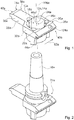
- Fig. 1 shows a tool insert and / or tool receiving insert 74a.
- the tool insert and / or tool holder insert 74a is designed as a tool tray insert and / or tool holder tray insert.
- the tool insert and / or tool receiving insert 74a has a base body 10a.
- the main body 10a has a plan view of a shape of a closed top Ypsilons 38a (see also Fig. 5c ).
- the main body 10a has a receiving region 14a.
- the receiving area 14a is formed as a recess 12a in the base body 10a.
- the recess 12a is formed continuously through the main body 10a.
- the receiving area 14a and / or the recess 12a may also be formed closed down.
- the receiving region 14a is provided for at least partially receiving at least one tool and / or at least one tool holder 16a (cf. Fig. 2 ).
- the tool and / or the tool holder 16a is introduced from above into a receiving direction 24a in the receiving area 14a.
- the receiving area 14a is arranged in a wide part of the shape of the closed top Ypsilons 38a.
- the receiving area 14a is disposed in a bifurcated portion of the y-shape of the shape of the closed-topped y-shape 38a.
- the receiving area 14a has an interior 46a.
- the interior 46a of the receiving region 14a is to be understood as a free volume formed by the depression 12a.
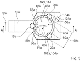
- the receiving area 14a has a center 102a (cf. Fig. 3 ).
- the center 102a of the receiving area 14a is arranged centrally in the receiving area 14a.
- the receiving area 14a has a receiving opening 66a.
- the receiving opening 66a is circular.
- the receiving opening 66a limits the receiving area 14a in FIG Recording direction 24a.
- the receiving opening 66a has a center 104a (cf. Fig. 3 ).
- the center 102a of the receiving area 14a and the center 104a of the receiving opening 66a are both arranged on a central axis 106a.
- the center 102a of the receiving region 14a is arranged laterally offset in the main body 10a.
- the center 104a of the receiving opening 66a is arranged laterally offset in the base body 10a.
- the receiving opening 66a has a transverse extent 90a (cf. Fig. 3 ).
- the transverse extent 90a of the receiving opening 66a runs parallel to a horizontal 62a.
- the transverse extent 90a of the receiving opening 66a corresponds to a diameter of the circular receiving opening 66a.
- the main body 10a has a mounting element 44a.
- the mounting element 44a is arranged on a further side wall 40a, 42a of the main body 10a.
- the mounting member 44a is provided for mounting the main body 10a on an external unit.
- the mounting member 44a is formed as a mounting rail.
- the mounting element 44a may also be formed as a hole, for example a screw and / or rivet hole, as a latching element and / or as another element which is suitable for mounting on an external unit.
- the main body 10a is screwless on an external unit, such as a mounting frame mounted.
- the main body 10a has a latching element (not shown).
- the latching element is intended for mounting the base body 10a on the external unit, for example the mounting frame.
- the latching element is arranged on a mounting element 44a opposite another side wall 42a.
- the locking element is intended to form a positive engagement with a corresponding locking element of the mounting frame.
- a lower handle which engages in at least a portion of the assembly and / or at least engages under the mounting frame, may be provided.
- an attachment of the main body 10a to the external unit, in particular the Mounting frame be provided by means of a screw.
- the main body 10a is chamfered on the sides of the further side walls 40a, 42a relative to the horizontal 62a.
- the bevel is intended for attachment of a label.
- the base body 10a in the bevelled area on a gedomten or lowered area 124a is provided for a, in particular slip-proof, attachment of a label, such as a sticker.
- the tool insert and / or tool receiving insert 74a has side walls 26a, 28a.
- the side walls 26a, 28a are formed complementary to each other.
- the side walls 26a, 28a are parallel to a receiving direction 24a of the receiving area 14a.
- the side walls 26a, 28a are arranged on two opposite outer sides of the main body 10a.
- the mutually complementary side walls 26a, 28a are intended to partially engage with side walls of other tool inserts and / or tool holder inserts.
- the side walls 26a, 28a have a stepped, in particular bevelled stepped, shape in a plan view.
- the side wall 26a has side surfaces 30a, 32a.
- the side surfaces 30a, 32a form contact surfaces to a further side wall.
- the side surfaces 30a, 32a of a side wall 26a of the complementary side walls 26a, 28a extend on at least two substantially different levels. Two of the planes defined by the side surfaces 30a, 32a of the side wall 26a of the mutually complementary side walls 26a, 28a are parallel to each other.
- the side surfaces 30a, 32a are flat.
- the side surfaces 30a, 32a are perpendicular to a horizontal surface of the main body 10a.
- the side surfaces 30a, 32a are connected to each other via a, another side surface forming another side wall.
- the tool insert and / or tool receiving insert 74a has a plurality of contact elements 18a, 20a, 22a.
- the tool insert and / or tool receiving insert 74a has three contact elements 18a, 20a, 22a.
- the contact elements 18a, 20a, 22a are provided for forming a contacting support of the tool and / or the tool holder 16a.
- the contact elements 18a, 20a, 22a each have a contact surface 56a, 58a, 60a.
- the contact surfaces 56a, 58a, 60a are provided for contacting a part of the tool inserted into the receiving region 14a and / or the tool holder 16a inserted into the receiving region 14a.
- the contact surfaces 56a, 58a, 60a are flat.
- the contact surfaces 56a, 58a, 60a may be at least partially bent and / or structured (cf. Fig. 10 ).
- the contact element 18a, 20a, 22a is partially flexible deformable.
- the contact surface 56a, 58a, 60a is partially flexibly deformable.
- An entire transverse extent 84a of the assembled contact element 20a in a horizontal direction is approximately 30% of the transverse extent 90a of the receiving opening 66a.
- the part of the contact element 18a, 20a, 22a which extends into the interior 46a of the receiving region 14a has a partially wedge-shaped outer shape 48a.
- the partially wedge-shaped outer shape 48a is formed as a truncated wedge shape.
- the contact element 18a, 20a, 22a runs in a receptive state of the Tool insert and / or the tool holder insert 74 a wedge-shaped in the direction of the interior 46 a of the receiving portion 14 a to.
- the contact element 18a, 20a, 22a has two side surfaces 50a, 52a.
- the wedge-shaped outer shape 48a of the contact elements 18a, 20a, 22a biases a wedge angle 54a between the two side surfaces 50a, 52a of the contact element 18a, 20a, 22a.
- the wedge angle 54a is 25 °.
- the contact element 18a, 20a, 22a is formed separately from the main body 10a.
- the contact element 18a, 20a, 22a is designed to be exchangeable.
- the main body 10a has a receiving element 114a for receiving a contact element 18a, 20a, 22a.
- the receiving element 114a is designed as a rail.
- the receiving element 114a has a latching mechanism for latching the contact element 18a, 20a, 22a after insertion into the receiving element 114a in a latching position.
- a locking mechanism can be realized, for example, by a positive connection of flexible plastic parts.
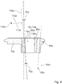
- Fig. 4 shows a side sectional view of a tool insert and / or tool receiving insert 74a along a in Fig. 3 indicated cutting plane A.
- the contact surfaces 56a, 58a, 60a have a tangent plane 108a in a portion of the contact element 18a, 20a, 22a.
- the tangential plane 108a has a normal vector 112a.
- the tangential plane 108a, in particular the normal vector 112a of the tangential plane 108a has a subcomponent 110a which runs parallel to the horizontal 62a in a mounting position of the tool insert and / or the tool receiving insert 74a.
- the tangential plane 108a in particular the normal vector 112a of the tangential plane 108a, has a sub-component 116a, which in an assembly position of the tool insert and / or the Tool holder insert 74a is perpendicular to the horizontal 62a.
- the normal vector 112a of the tangential plane 108a forms a linear combination of the vertical subcomponent 116a and the horizontal subcomponent 110a.
- the contact element 18a, 20a, 22a has an outer shape.
- the outer shape of the contact element 18a, 20a, 22a has a steadily increasing course in a direction perpendicular to the receiving direction 24a of the receiving region 14a.
- the outer shape could have a steadily decreasing profile and / or a course that changes at least once, preferably several times, between a steady increase and a steady decrease.
- the contact surface 56a, 58a, 60a of the contact element 18a, 20a, 22a is angled relative to an extrusion 64a of the receiving opening 66a.
- An angle 70a including the contact surface 56a, 58a, 60a and the extrusion 64a of the receiving opening 66a is 3 °.
- the contact surface 56a, 58a, 60a of the contact element 18a, 20a, 22a is angled relative to an extension 68a of the receiving region 14a in the receiving direction 24a.
- Another angle 72a which includes the contact surface 56a, 58a, 60a and the extension 68a of the receiving area 14a is 2 °.
- the angle 70a which includes the contact surface 56a, 58a, 60a and the extrusion 64a of the receiving opening 66a and the further angle 72a which the contact surface 56a, 58a, 60a and the extension 68a of the receiving area 14a include are of different sizes.
- the angle 70a which the contact surface 56a, 58a, 60a and the extrusion 64a of the receiving opening 66a enclose is greater than the further angle 72a which the contact surface 56a, 58a, 60a and the extension 68a of the receiving area 14a include.
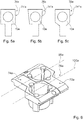
- Fig. 5 shows different forms of the tool insert and / or tool receiving insert 74'a, 74 "a, 74"'a in a plan view.
- Fig. 5a shows a tool insert and / or tool receiving insert 74'a, which a Shovel 34a forms.
- Fig. 5b shows a tool insert and / or tool receiving insert 74 "a, which forms a spatula mold 36a.
- Fig. 5c shows a tool insert and / or tool receiving insert 74 "'a, which forms a shape of a closed top Ypsilons 38a.
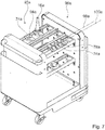
- Fig. 7 shows a tool and / or tool receiving bearing system 96a with tool inserts and / or tool receiving inserts 74a, 78a.
- the tool and / or tool receiving storage system 96a has a tool storage unit 92a.
- the tool storage unit 92a is designed as a mobile trolley.
- the tool storage unit 92a has mounting rails 94a.
- the mounting rails 94a are provided for mounting tool inserts and / or tool receiving inserts 74a, 78a.
- the mounting rail 94a is for mounting the tool inserts and / or tool receiving inserts 74a, 78a by means of their mounting member 44a intended.
- the tool storage unit 92a forms an external unit.
- Systems 76a of tool inserts and / or tool receiving inserts 74a, 78a can be mounted in a mounting rail 94a of the tool storage unit 92a.
- the tool inserts and / or tool receiving inserts 74a, 78a of a system 76a of tool inserts and / or tool receiving inserts 74a, 78a are positioned in the mounting rail 94a so that receiving openings 66a of the receiving areas 14a of the tool inserts and / or tool receiving inserts 74a, 78a in two parallel, laterally to each other staggered rows 98a, 100a are arranged.
- the part of the further contact element 82a which protrudes into the receiving area 14a when the further contact element 82a is mounted in a mounting position of the tool insert and / or the tool receiving insert 74a, has a horizontal transverse extent 88a which corresponds to at least 10% of a maximum horizontal transverse extent 90a of the receiving area 14a (see also Fig. 3 ).
- Fig. 9 shows a section of a schematic sectional view of a tool insert and / or tool holder insert 74b with an alternative contact element 18b along a sectional plane A (see. Fig. 3 ).
- the contact element 18b is formed bent.
- the contact element 18b has a contact surface 56b.
- the contact surface 56b is formed curved.
- the contact element 18b is flexible.
- the contact element 18b forms a bending spring.
- the bending spring is biased substantially in a spring direction 118b.
- the spring direction 118b extends substantially perpendicular to a receiving direction 24b into which a tool and / or a tool holder 16b is moved during storage in a receiving area 14b of the tool insert and / or tool receiving insert 74b.
- the contact surface 56b is bent in a direction parallel to the receiving direction 24b of the receiving portion 14b.
- a radius of curvature 120b of the curvature of the curved or contact surface 56b lies in a plane with the cutting plane A.
Landscapes
- Engineering & Computer Science (AREA)
- Mechanical Engineering (AREA)
- General Engineering & Computer Science (AREA)
- Purses, Travelling Bags, Baskets, Or Suitcases (AREA)
- Workshop Equipment, Work Benches, Supports, Or Storage Means (AREA)
- Cutting Tools, Boring Holders, And Turrets (AREA)
Applications Claiming Priority (1)
| Application Number | Priority Date | Filing Date | Title |
|---|---|---|---|
| DE202018100425.5U DE202018100425U1 (de) | 2018-01-25 | 2018-01-25 | Werkzeugeinsatz und/oder Werkzeugaufnahmeeinsatz, Werkzeugeinsatz- und/oder Werkzeugaufnahmeeinsatzsystem und Werkzeug- und/oder Werkzeugaufnahmelagersystem |
Publications (3)
| Publication Number | Publication Date |
|---|---|
| EP3552771A2 true EP3552771A2 (fr) | 2019-10-16 |
| EP3552771A3 EP3552771A3 (fr) | 2019-12-25 |
| EP3552771B1 EP3552771B1 (fr) | 2023-04-05 |
Family
ID=61247263
Family Applications (1)
| Application Number | Title | Priority Date | Filing Date |
|---|---|---|---|
| EP19152426.3A Active EP3552771B1 (fr) | 2018-01-25 | 2019-01-18 | Insert d'outil et / ou insert logement d'outil, système d'insert d'outil et / ou d'insert logement d'outil et système de stockage d'outil et / ou de logement d'outil |
Country Status (3)
| Country | Link |
|---|---|
| US (1) | US10710233B2 (fr) |
| EP (1) | EP3552771B1 (fr) |
| DE (1) | DE202018100425U1 (fr) |
Families Citing this family (7)
| Publication number | Priority date | Publication date | Assignee | Title |
|---|---|---|---|---|
| USD940461S1 (en) * | 2019-08-07 | 2022-01-11 | Rousseau Métal Inc. | Tool rack |
| EP4039407B1 (fr) * | 2019-09-30 | 2026-04-29 | Mori Machinery Corporation | Magasin d'outils |
| DE102020130799A1 (de) * | 2020-11-20 | 2022-05-25 | E. Zoller GmbH & Co. KG Einstell- und Messgeräte | Bestückungsvorrichtung, Bestückungssystem, Transportsystem, Anlage und Verfahren zu einer Bestückung der Anlage |
| CN112571393B (zh) * | 2020-12-26 | 2022-04-12 | 广州奕极机电科技有限公司 | 一种化妆品加工车间用便于运输的化妆品放置架 |
| DE102021119631A1 (de) * | 2021-07-28 | 2023-02-02 | Andreas Böhm | Vorrichtung zur Aufbewahrung von Werkzeugen |
| US12318909B2 (en) * | 2021-08-04 | 2025-06-03 | Matthias Keller | Power tool and battery support racks and methods of manufacturing |
| US12083665B2 (en) * | 2023-01-04 | 2024-09-10 | Shin-Yain Industrial Co., Ltd. | Tool holder module |
Family Cites Families (16)
| Publication number | Priority date | Publication date | Assignee | Title |
|---|---|---|---|---|
| US3684101A (en) | 1970-09-21 | 1972-08-15 | Glenn H Bradford | Tool loader and unloader |
| DE2619151C3 (de) * | 1976-04-30 | 1980-12-18 | Kelch Gmbh U. Co Werkzeugmaschinenfabrik, 7060 Schorndorf | Lagereinrichtung für Werkzeuge |
| IT7720827U1 (it) | 1977-03-04 | 1978-09-04 | Susta Spa | Supporto per l'alloggiamento della presentazione di utensili, specialmente utilizzabili su macchine a controllo numerico |
| US4410095A (en) * | 1980-11-05 | 1983-10-18 | Southern Case, Inc. | Interlocking modular article supporting system and component units therefor |
| DE3234773C2 (de) | 1982-09-20 | 1985-04-04 | Autz & Herrmann, 6900 Heidelberg | Werkzeugablageeinrichtung |
| EP0104866A1 (fr) | 1982-09-23 | 1984-04-04 | Linvar Limited | Supports d'outil |
| US4535897A (en) * | 1983-09-06 | 1985-08-20 | The Stanley Works | Tool handling and transportation system |
| CH665991A5 (de) * | 1984-02-10 | 1988-06-30 | Zoelling Paul Ag | Werkzeugtraeger. |
| US5050756A (en) * | 1984-07-13 | 1991-09-24 | Lista Ag | Method and apparatus for storing, transporting and transferring production goods |
| US4770297A (en) * | 1987-08-17 | 1988-09-13 | Chang Yen Nien | Assembling tool-holder set |
| DE8716734U1 (de) * | 1987-12-18 | 1988-02-04 | Klarer, Christoph, 8028 Taufkirchen | Schutzhaube für eine Werkzeug-Aufnahme |
| DE29710341U1 (de) | 1997-06-13 | 1998-10-08 | KB Knecht GmbH Betriebseinrichtungen, 72766 Reutlingen | Tragevorrichtung für Werkzeuge |
| US6047827A (en) * | 1999-03-22 | 2000-04-11 | Huang; Hung Chen | Assembling bit receiving device |
| EP1175287A1 (fr) * | 1999-04-30 | 2002-01-30 | Lista Europe Holding AG | Systeme de stockage d'outils |
| EP1547725B1 (fr) * | 2003-12-25 | 2007-01-10 | Aoi Seiko Co., Ltd. | Case porte-outil |
| DE202013105024U1 (de) * | 2013-11-07 | 2014-01-14 | Liu Chia-Chun | Werkzeugkasten |
-
2018
- 2018-01-25 DE DE202018100425.5U patent/DE202018100425U1/de not_active Expired - Lifetime
-
2019
- 2019-01-18 EP EP19152426.3A patent/EP3552771B1/fr active Active
- 2019-01-23 US US16/254,702 patent/US10710233B2/en active Active
Also Published As
| Publication number | Publication date |
|---|---|
| US20190224839A1 (en) | 2019-07-25 |
| EP3552771A3 (fr) | 2019-12-25 |
| US10710233B2 (en) | 2020-07-14 |
| DE202018100425U1 (de) | 2018-02-05 |
| EP3552771B1 (fr) | 2023-04-05 |
Similar Documents
| Publication | Publication Date | Title |
|---|---|---|
| EP3552771A2 (fr) | Insert d'outil et / ou insert logement d'outil, système d'insert d'outil et / ou d'insert logement d'outil et système de stockage d'outil et / ou de logement d'outil | |
| DE69520505T2 (de) | Nutenfräser | |
| DE69705042T2 (de) | Rasiersystem und verfahren | |
| DE3710016C2 (fr) | ||
| DE29816671U1 (de) | Werkzeughalter mit verschiebbaren Verbindern | |
| DE19925176A1 (de) | Werkzeughalter für Sechskantschlüssel | |
| EP3909477A1 (fr) | Attache rideau | |
| EP2848337B1 (fr) | Agencement de mâchoire de serrage | |
| EP0116260B1 (fr) | Dispositif pour fixer un objet | |
| EP2412490B1 (fr) | Système de fixation | |
| EP0539687A1 (fr) | Joint perpendiculaire pour des profilés avec des rainures longitudinales | |
| DE102015105402A1 (de) | Behälter für Werkzeuge und Werkzeugteile und dessen Verwendung | |
| DE8326465U1 (de) | Vorrichtung mit Profilschiene sowie dieser zugeordnetem Halteorgan | |
| EP2357690A1 (fr) | Batterie et appareil électrique avec système de codage tridimensionnel | |
| EP3986821A1 (fr) | Système de buses pour machine textile, système de vis pour système de fixation rapide et machine textile équipée du système de buses | |
| EP4424481A2 (fr) | Appareil de coupe permettant de découper des tubes ou des manchons | |
| EP0619167A1 (fr) | Couteau de poche | |
| EP2797787B1 (fr) | Dispositif de balai d'essuie-glace | |
| EP3462042B1 (fr) | Dispositif de fixation et composant pour un tel dispositif de fixation | |
| EP3025938B1 (fr) | Dispositif de recouvrement pour une face d'un element de paroi | |
| EP2845693B1 (fr) | Système adaptateur pour un outil | |
| EP0649361B1 (fr) | Agrafeuse | |
| DE102009000990A1 (de) | Schlüssel für einen Schließzylinder | |
| EP0424747B1 (fr) | Dispositif de liaison de deux pièces d'armoire en particulier du socle d'une armoire de distribution de câbles avec celle-ci | |
| DE202005019483U1 (de) | Führungsschienensystem |
Legal Events
| Date | Code | Title | Description |
|---|---|---|---|
| PUAI | Public reference made under article 153(3) epc to a published international application that has entered the european phase |
Free format text: ORIGINAL CODE: 0009012 |
|
| STAA | Information on the status of an ep patent application or granted ep patent |
Free format text: STATUS: THE APPLICATION HAS BEEN PUBLISHED |
|
| AK | Designated contracting states |
Kind code of ref document: A2 Designated state(s): AL AT BE BG CH CY CZ DE DK EE ES FI FR GB GR HR HU IE IS IT LI LT LU LV MC MK MT NL NO PL PT RO RS SE SI SK SM TR |
|
| AX | Request for extension of the european patent |
Extension state: BA ME |
|
| PUAL | Search report despatched |
Free format text: ORIGINAL CODE: 0009013 |
|
| AK | Designated contracting states |
Kind code of ref document: A3 Designated state(s): AL AT BE BG CH CY CZ DE DK EE ES FI FR GB GR HR HU IE IS IT LI LT LU LV MC MK MT NL NO PL PT RO RS SE SI SK SM TR |
|
| AX | Request for extension of the european patent |
Extension state: BA ME |
|
| RIC1 | Information provided on ipc code assigned before grant |
Ipc: B25H 3/00 20060101ALI20191118BHEP Ipc: B25H 3/04 20060101AFI20191118BHEP |
|
| STAA | Information on the status of an ep patent application or granted ep patent |
Free format text: STATUS: REQUEST FOR EXAMINATION WAS MADE |
|
| 17P | Request for examination filed |
Effective date: 20200331 |
|
| RBV | Designated contracting states (corrected) |
Designated state(s): AL AT BE BG CH CY CZ DE DK EE ES FI FR GB GR HR HU IE IS IT LI LT LU LV MC MK MT NL NO PL PT RO RS SE SI SK SM TR |
|
| STAA | Information on the status of an ep patent application or granted ep patent |
Free format text: STATUS: EXAMINATION IS IN PROGRESS |
|
| 17Q | First examination report despatched |
Effective date: 20211222 |
|
| GRAP | Despatch of communication of intention to grant a patent |
Free format text: ORIGINAL CODE: EPIDOSNIGR1 |
|
| STAA | Information on the status of an ep patent application or granted ep patent |
Free format text: STATUS: GRANT OF PATENT IS INTENDED |
|
| INTG | Intention to grant announced |
Effective date: 20221021 |
|
| GRAS | Grant fee paid |
Free format text: ORIGINAL CODE: EPIDOSNIGR3 |
|
| GRAA | (expected) grant |
Free format text: ORIGINAL CODE: 0009210 |
|
| STAA | Information on the status of an ep patent application or granted ep patent |
Free format text: STATUS: THE PATENT HAS BEEN GRANTED |
|
| AK | Designated contracting states |
Kind code of ref document: B1 Designated state(s): AL AT BE BG CH CY CZ DE DK EE ES FI FR GB GR HR HU IE IS IT LI LT LU LV MC MK MT NL NO PL PT RO RS SE SI SK SM TR |
|
| REG | Reference to a national code |
Ref country code: GB Ref legal event code: FG4D Free format text: NOT ENGLISH |
|
| REG | Reference to a national code |
Ref country code: CH Ref legal event code: EP |
|
| REG | Reference to a national code |
Ref country code: AT Ref legal event code: REF Ref document number: 1557883 Country of ref document: AT Kind code of ref document: T Effective date: 20230415 |
|
| REG | Reference to a national code |
Ref country code: DE Ref legal event code: R096 Ref document number: 502019007371 Country of ref document: DE |
|
| REG | Reference to a national code |
Ref country code: IE Ref legal event code: FG4D Free format text: LANGUAGE OF EP DOCUMENT: GERMAN |
|
| P01 | Opt-out of the competence of the unified patent court (upc) registered |
Effective date: 20230522 |
|
| REG | Reference to a national code |
Ref country code: LT Ref legal event code: MG9D |
|
| REG | Reference to a national code |
Ref country code: NL Ref legal event code: MP Effective date: 20230405 |
|
| PG25 | Lapsed in a contracting state [announced via postgrant information from national office to epo] |
Ref country code: NL Free format text: LAPSE BECAUSE OF FAILURE TO SUBMIT A TRANSLATION OF THE DESCRIPTION OR TO PAY THE FEE WITHIN THE PRESCRIBED TIME-LIMIT Effective date: 20230405 |
|
| PG25 | Lapsed in a contracting state [announced via postgrant information from national office to epo] |
Ref country code: SE Free format text: LAPSE BECAUSE OF FAILURE TO SUBMIT A TRANSLATION OF THE DESCRIPTION OR TO PAY THE FEE WITHIN THE PRESCRIBED TIME-LIMIT Effective date: 20230405 Ref country code: PT Free format text: LAPSE BECAUSE OF FAILURE TO SUBMIT A TRANSLATION OF THE DESCRIPTION OR TO PAY THE FEE WITHIN THE PRESCRIBED TIME-LIMIT Effective date: 20230807 Ref country code: NO Free format text: LAPSE BECAUSE OF FAILURE TO SUBMIT A TRANSLATION OF THE DESCRIPTION OR TO PAY THE FEE WITHIN THE PRESCRIBED TIME-LIMIT Effective date: 20230705 Ref country code: ES Free format text: LAPSE BECAUSE OF FAILURE TO SUBMIT A TRANSLATION OF THE DESCRIPTION OR TO PAY THE FEE WITHIN THE PRESCRIBED TIME-LIMIT Effective date: 20230405 |
|
| PG25 | Lapsed in a contracting state [announced via postgrant information from national office to epo] |
Ref country code: RS Free format text: LAPSE BECAUSE OF FAILURE TO SUBMIT A TRANSLATION OF THE DESCRIPTION OR TO PAY THE FEE WITHIN THE PRESCRIBED TIME-LIMIT Effective date: 20230405 Ref country code: PL Free format text: LAPSE BECAUSE OF FAILURE TO SUBMIT A TRANSLATION OF THE DESCRIPTION OR TO PAY THE FEE WITHIN THE PRESCRIBED TIME-LIMIT Effective date: 20230405 Ref country code: LV Free format text: LAPSE BECAUSE OF FAILURE TO SUBMIT A TRANSLATION OF THE DESCRIPTION OR TO PAY THE FEE WITHIN THE PRESCRIBED TIME-LIMIT Effective date: 20230405 Ref country code: LT Free format text: LAPSE BECAUSE OF FAILURE TO SUBMIT A TRANSLATION OF THE DESCRIPTION OR TO PAY THE FEE WITHIN THE PRESCRIBED TIME-LIMIT Effective date: 20230405 Ref country code: IS Free format text: LAPSE BECAUSE OF FAILURE TO SUBMIT A TRANSLATION OF THE DESCRIPTION OR TO PAY THE FEE WITHIN THE PRESCRIBED TIME-LIMIT Effective date: 20230805 Ref country code: HR Free format text: LAPSE BECAUSE OF FAILURE TO SUBMIT A TRANSLATION OF THE DESCRIPTION OR TO PAY THE FEE WITHIN THE PRESCRIBED TIME-LIMIT Effective date: 20230405 Ref country code: GR Free format text: LAPSE BECAUSE OF FAILURE TO SUBMIT A TRANSLATION OF THE DESCRIPTION OR TO PAY THE FEE WITHIN THE PRESCRIBED TIME-LIMIT Effective date: 20230706 Ref country code: AL Free format text: LAPSE BECAUSE OF FAILURE TO SUBMIT A TRANSLATION OF THE DESCRIPTION OR TO PAY THE FEE WITHIN THE PRESCRIBED TIME-LIMIT Effective date: 20230405 |
|
| PG25 | Lapsed in a contracting state [announced via postgrant information from national office to epo] |
Ref country code: FI Free format text: LAPSE BECAUSE OF FAILURE TO SUBMIT A TRANSLATION OF THE DESCRIPTION OR TO PAY THE FEE WITHIN THE PRESCRIBED TIME-LIMIT Effective date: 20230405 |
|
| REG | Reference to a national code |
Ref country code: DE Ref legal event code: R097 Ref document number: 502019007371 Country of ref document: DE |
|
| PG25 | Lapsed in a contracting state [announced via postgrant information from national office to epo] |
Ref country code: SK Free format text: LAPSE BECAUSE OF FAILURE TO SUBMIT A TRANSLATION OF THE DESCRIPTION OR TO PAY THE FEE WITHIN THE PRESCRIBED TIME-LIMIT Effective date: 20230405 |
|
| PG25 | Lapsed in a contracting state [announced via postgrant information from national office to epo] |
Ref country code: SM Free format text: LAPSE BECAUSE OF FAILURE TO SUBMIT A TRANSLATION OF THE DESCRIPTION OR TO PAY THE FEE WITHIN THE PRESCRIBED TIME-LIMIT Effective date: 20230405 Ref country code: SK Free format text: LAPSE BECAUSE OF FAILURE TO SUBMIT A TRANSLATION OF THE DESCRIPTION OR TO PAY THE FEE WITHIN THE PRESCRIBED TIME-LIMIT Effective date: 20230405 Ref country code: RO Free format text: LAPSE BECAUSE OF FAILURE TO SUBMIT A TRANSLATION OF THE DESCRIPTION OR TO PAY THE FEE WITHIN THE PRESCRIBED TIME-LIMIT Effective date: 20230405 Ref country code: EE Free format text: LAPSE BECAUSE OF FAILURE TO SUBMIT A TRANSLATION OF THE DESCRIPTION OR TO PAY THE FEE WITHIN THE PRESCRIBED TIME-LIMIT Effective date: 20230405 Ref country code: DK Free format text: LAPSE BECAUSE OF FAILURE TO SUBMIT A TRANSLATION OF THE DESCRIPTION OR TO PAY THE FEE WITHIN THE PRESCRIBED TIME-LIMIT Effective date: 20230405 Ref country code: CZ Free format text: LAPSE BECAUSE OF FAILURE TO SUBMIT A TRANSLATION OF THE DESCRIPTION OR TO PAY THE FEE WITHIN THE PRESCRIBED TIME-LIMIT Effective date: 20230405 |
|
| PLBE | No opposition filed within time limit |
Free format text: ORIGINAL CODE: 0009261 |
|
| STAA | Information on the status of an ep patent application or granted ep patent |
Free format text: STATUS: NO OPPOSITION FILED WITHIN TIME LIMIT |
|
| 26N | No opposition filed |
Effective date: 20240108 |
|
| PG25 | Lapsed in a contracting state [announced via postgrant information from national office to epo] |
Ref country code: SI Free format text: LAPSE BECAUSE OF FAILURE TO SUBMIT A TRANSLATION OF THE DESCRIPTION OR TO PAY THE FEE WITHIN THE PRESCRIBED TIME-LIMIT Effective date: 20230405 |
|
| PG25 | Lapsed in a contracting state [announced via postgrant information from national office to epo] |
Ref country code: SI Free format text: LAPSE BECAUSE OF FAILURE TO SUBMIT A TRANSLATION OF THE DESCRIPTION OR TO PAY THE FEE WITHIN THE PRESCRIBED TIME-LIMIT Effective date: 20230405 Ref country code: IT Free format text: LAPSE BECAUSE OF FAILURE TO SUBMIT A TRANSLATION OF THE DESCRIPTION OR TO PAY THE FEE WITHIN THE PRESCRIBED TIME-LIMIT Effective date: 20230405 |
|
| PG25 | Lapsed in a contracting state [announced via postgrant information from national office to epo] |
Ref country code: MC Free format text: LAPSE BECAUSE OF FAILURE TO SUBMIT A TRANSLATION OF THE DESCRIPTION OR TO PAY THE FEE WITHIN THE PRESCRIBED TIME-LIMIT Effective date: 20230405 |
|
| PG25 | Lapsed in a contracting state [announced via postgrant information from national office to epo] |
Ref country code: MC Free format text: LAPSE BECAUSE OF FAILURE TO SUBMIT A TRANSLATION OF THE DESCRIPTION OR TO PAY THE FEE WITHIN THE PRESCRIBED TIME-LIMIT Effective date: 20230405 |
|
| REG | Reference to a national code |
Ref country code: CH Ref legal event code: PL |
|
| PG25 | Lapsed in a contracting state [announced via postgrant information from national office to epo] |
Ref country code: LU Free format text: LAPSE BECAUSE OF NON-PAYMENT OF DUE FEES Effective date: 20240118 |
|
| PG25 | Lapsed in a contracting state [announced via postgrant information from national office to epo] |
Ref country code: LU Free format text: LAPSE BECAUSE OF NON-PAYMENT OF DUE FEES Effective date: 20240118 |
|
| PG25 | Lapsed in a contracting state [announced via postgrant information from national office to epo] |
Ref country code: BE Free format text: LAPSE BECAUSE OF NON-PAYMENT OF DUE FEES Effective date: 20240131 |
|
| PG25 | Lapsed in a contracting state [announced via postgrant information from national office to epo] |
Ref country code: CH Free format text: LAPSE BECAUSE OF NON-PAYMENT OF DUE FEES Effective date: 20240131 |
|
| PG25 | Lapsed in a contracting state [announced via postgrant information from national office to epo] |
Ref country code: CH Free format text: LAPSE BECAUSE OF NON-PAYMENT OF DUE FEES Effective date: 20240131 Ref country code: BE Free format text: LAPSE BECAUSE OF NON-PAYMENT OF DUE FEES Effective date: 20240131 |
|
| REG | Reference to a national code |
Ref country code: BE Ref legal event code: MM Effective date: 20240131 |
|
| PG25 | Lapsed in a contracting state [announced via postgrant information from national office to epo] |
Ref country code: BG Free format text: LAPSE BECAUSE OF FAILURE TO SUBMIT A TRANSLATION OF THE DESCRIPTION OR TO PAY THE FEE WITHIN THE PRESCRIBED TIME-LIMIT Effective date: 20230405 |
|
| PG25 | Lapsed in a contracting state [announced via postgrant information from national office to epo] |
Ref country code: BG Free format text: LAPSE BECAUSE OF FAILURE TO SUBMIT A TRANSLATION OF THE DESCRIPTION OR TO PAY THE FEE WITHIN THE PRESCRIBED TIME-LIMIT Effective date: 20230405 |
|
| PG25 | Lapsed in a contracting state [announced via postgrant information from national office to epo] |
Ref country code: IE Free format text: LAPSE BECAUSE OF NON-PAYMENT OF DUE FEES Effective date: 20240118 |
|
| PG25 | Lapsed in a contracting state [announced via postgrant information from national office to epo] |
Ref country code: IE Free format text: LAPSE BECAUSE OF NON-PAYMENT OF DUE FEES Effective date: 20240118 |
|
| REG | Reference to a national code |
Ref country code: AT Ref legal event code: MM01 Ref document number: 1557883 Country of ref document: AT Kind code of ref document: T Effective date: 20240118 |
|
| PG25 | Lapsed in a contracting state [announced via postgrant information from national office to epo] |
Ref country code: AT Free format text: LAPSE BECAUSE OF NON-PAYMENT OF DUE FEES Effective date: 20240118 |
|
| PG25 | Lapsed in a contracting state [announced via postgrant information from national office to epo] |
Ref country code: CY Free format text: LAPSE BECAUSE OF FAILURE TO SUBMIT A TRANSLATION OF THE DESCRIPTION OR TO PAY THE FEE WITHIN THE PRESCRIBED TIME-LIMIT; INVALID AB INITIO Effective date: 20190118 |
|
| PG25 | Lapsed in a contracting state [announced via postgrant information from national office to epo] |
Ref country code: HU Free format text: LAPSE BECAUSE OF FAILURE TO SUBMIT A TRANSLATION OF THE DESCRIPTION OR TO PAY THE FEE WITHIN THE PRESCRIBED TIME-LIMIT; INVALID AB INITIO Effective date: 20190118 |
|
| PG25 | Lapsed in a contracting state [announced via postgrant information from national office to epo] |
Ref country code: TR Free format text: LAPSE BECAUSE OF FAILURE TO SUBMIT A TRANSLATION OF THE DESCRIPTION OR TO PAY THE FEE WITHIN THE PRESCRIBED TIME-LIMIT Effective date: 20230405 |
|
| PGFP | Annual fee paid to national office [announced via postgrant information from national office to epo] |
Ref country code: GB Payment date: 20260122 Year of fee payment: 8 |
|
| PGFP | Annual fee paid to national office [announced via postgrant information from national office to epo] |
Ref country code: DE Payment date: 20260131 Year of fee payment: 8 |
|
| PGFP | Annual fee paid to national office [announced via postgrant information from national office to epo] |
Ref country code: FR Payment date: 20260128 Year of fee payment: 8 |