EP3552711B1 - Electrostatic filter unit and ventilation device with electrostatic filter unit - Google Patents
Electrostatic filter unit and ventilation device with electrostatic filter unit Download PDFInfo
- Publication number
- EP3552711B1 EP3552711B1 EP19163448.4A EP19163448A EP3552711B1 EP 3552711 B1 EP3552711 B1 EP 3552711B1 EP 19163448 A EP19163448 A EP 19163448A EP 3552711 B1 EP3552711 B1 EP 3552711B1
- Authority
- EP
- European Patent Office
- Prior art keywords
- filter unit
- electrostatic filter
- slot
- holding device
- unit according
- Prior art date
- Legal status (The legal status is an assumption and is not a legal conclusion. Google has not performed a legal analysis and makes no representation as to the accuracy of the status listed.)
- Active
Links
- 238000009423 ventilation Methods 0.000 title claims description 33
- 238000001556 precipitation Methods 0.000 claims description 18
- 239000004020 conductor Substances 0.000 claims description 13
- 238000001746 injection moulding Methods 0.000 claims description 4
- 239000012811 non-conductive material Substances 0.000 claims description 4
- 230000008021 deposition Effects 0.000 description 68
- 238000000926 separation method Methods 0.000 description 22
- 238000009413 insulation Methods 0.000 description 9
- 229910052751 metal Inorganic materials 0.000 description 8
- 239000002184 metal Substances 0.000 description 8
- 238000004519 manufacturing process Methods 0.000 description 7
- 239000011248 coating agent Substances 0.000 description 6
- 238000000576 coating method Methods 0.000 description 6
- 239000002245 particle Substances 0.000 description 6
- 239000000463 material Substances 0.000 description 5
- 239000004033 plastic Substances 0.000 description 5
- 229920003023 plastic Polymers 0.000 description 5
- 239000000428 dust Substances 0.000 description 4
- 230000005684 electric field Effects 0.000 description 4
- 239000012530 fluid Substances 0.000 description 4
- 239000012535 impurity Substances 0.000 description 4
- 229910052782 aluminium Inorganic materials 0.000 description 2
- XAGFODPZIPBFFR-UHFFFAOYSA-N aluminium Chemical compound [Al] XAGFODPZIPBFFR-UHFFFAOYSA-N 0.000 description 2
- 239000012717 electrostatic precipitator Substances 0.000 description 2
- 239000006260 foam Substances 0.000 description 2
- 239000012212 insulator Substances 0.000 description 2
- 239000007788 liquid Substances 0.000 description 2
- 230000001681 protective effect Effects 0.000 description 2
- 239000007787 solid Substances 0.000 description 2
- 230000001133 acceleration Effects 0.000 description 1
- 230000004308 accommodation Effects 0.000 description 1
- 238000003915 air pollution Methods 0.000 description 1
- 238000003491 array Methods 0.000 description 1
- 238000005452 bending Methods 0.000 description 1
- 230000015572 biosynthetic process Effects 0.000 description 1
- 239000003990 capacitor Substances 0.000 description 1
- 238000005266 casting Methods 0.000 description 1
- 230000015556 catabolic process Effects 0.000 description 1
- 150000001875 compounds Chemical class 0.000 description 1
- 239000011231 conductive filler Substances 0.000 description 1
- 229920001940 conductive polymer Polymers 0.000 description 1
- 238000010276 construction Methods 0.000 description 1
- 238000010411 cooking Methods 0.000 description 1
- 239000012777 electrically insulating material Substances 0.000 description 1
- 238000005516 engineering process Methods 0.000 description 1
- 239000003517 fume Substances 0.000 description 1
- 238000007373 indentation Methods 0.000 description 1
- 238000003780 insertion Methods 0.000 description 1
- 230000037431 insertion Effects 0.000 description 1
- 239000011810 insulating material Substances 0.000 description 1
- 238000002955 isolation Methods 0.000 description 1
- 150000002739 metals Chemical class 0.000 description 1
- 238000000034 method Methods 0.000 description 1
- 238000005192 partition Methods 0.000 description 1
- 229920000642 polymer Polymers 0.000 description 1
- 230000001376 precipitating effect Effects 0.000 description 1
- 230000036316 preload Effects 0.000 description 1
- 239000011343 solid material Substances 0.000 description 1
- 239000000243 solution Substances 0.000 description 1
- 125000006850 spacer group Chemical group 0.000 description 1
- 239000000126 substance Substances 0.000 description 1
- 239000000725 suspension Substances 0.000 description 1
- 238000011144 upstream manufacturing Methods 0.000 description 1
Images


Classifications
-
- B—PERFORMING OPERATIONS; TRANSPORTING
- B03—SEPARATION OF SOLID MATERIALS USING LIQUIDS OR USING PNEUMATIC TABLES OR JIGS; MAGNETIC OR ELECTROSTATIC SEPARATION OF SOLID MATERIALS FROM SOLID MATERIALS OR FLUIDS; SEPARATION BY HIGH-VOLTAGE ELECTRIC FIELDS
- B03C—MAGNETIC OR ELECTROSTATIC SEPARATION OF SOLID MATERIALS FROM SOLID MATERIALS OR FLUIDS; SEPARATION BY HIGH-VOLTAGE ELECTRIC FIELDS
- B03C3/00—Separating dispersed particles from gases or vapour, e.g. air, by electrostatic effect
- B03C3/34—Constructional details or accessories or operation thereof
- B03C3/86—Electrode-carrying means
-
- B—PERFORMING OPERATIONS; TRANSPORTING
- B03—SEPARATION OF SOLID MATERIALS USING LIQUIDS OR USING PNEUMATIC TABLES OR JIGS; MAGNETIC OR ELECTROSTATIC SEPARATION OF SOLID MATERIALS FROM SOLID MATERIALS OR FLUIDS; SEPARATION BY HIGH-VOLTAGE ELECTRIC FIELDS
- B03C—MAGNETIC OR ELECTROSTATIC SEPARATION OF SOLID MATERIALS FROM SOLID MATERIALS OR FLUIDS; SEPARATION BY HIGH-VOLTAGE ELECTRIC FIELDS
- B03C3/00—Separating dispersed particles from gases or vapour, e.g. air, by electrostatic effect
- B03C3/017—Combinations of electrostatic separation with other processes, not otherwise provided for
-
- B—PERFORMING OPERATIONS; TRANSPORTING
- B03—SEPARATION OF SOLID MATERIALS USING LIQUIDS OR USING PNEUMATIC TABLES OR JIGS; MAGNETIC OR ELECTROSTATIC SEPARATION OF SOLID MATERIALS FROM SOLID MATERIALS OR FLUIDS; SEPARATION BY HIGH-VOLTAGE ELECTRIC FIELDS
- B03C—MAGNETIC OR ELECTROSTATIC SEPARATION OF SOLID MATERIALS FROM SOLID MATERIALS OR FLUIDS; SEPARATION BY HIGH-VOLTAGE ELECTRIC FIELDS
- B03C3/00—Separating dispersed particles from gases or vapour, e.g. air, by electrostatic effect
- B03C3/02—Plant or installations having external electricity supply
- B03C3/04—Plant or installations having external electricity supply dry type
- B03C3/08—Plant or installations having external electricity supply dry type characterised by presence of stationary flat electrodes arranged with their flat surfaces parallel to the gas stream
-
- B—PERFORMING OPERATIONS; TRANSPORTING
- B03—SEPARATION OF SOLID MATERIALS USING LIQUIDS OR USING PNEUMATIC TABLES OR JIGS; MAGNETIC OR ELECTROSTATIC SEPARATION OF SOLID MATERIALS FROM SOLID MATERIALS OR FLUIDS; SEPARATION BY HIGH-VOLTAGE ELECTRIC FIELDS
- B03C—MAGNETIC OR ELECTROSTATIC SEPARATION OF SOLID MATERIALS FROM SOLID MATERIALS OR FLUIDS; SEPARATION BY HIGH-VOLTAGE ELECTRIC FIELDS
- B03C3/00—Separating dispersed particles from gases or vapour, e.g. air, by electrostatic effect
- B03C3/02—Plant or installations having external electricity supply
- B03C3/04—Plant or installations having external electricity supply dry type
- B03C3/12—Plant or installations having external electricity supply dry type characterised by separation of ionising and collecting stations
-
- B—PERFORMING OPERATIONS; TRANSPORTING
- B03—SEPARATION OF SOLID MATERIALS USING LIQUIDS OR USING PNEUMATIC TABLES OR JIGS; MAGNETIC OR ELECTROSTATIC SEPARATION OF SOLID MATERIALS FROM SOLID MATERIALS OR FLUIDS; SEPARATION BY HIGH-VOLTAGE ELECTRIC FIELDS
- B03C—MAGNETIC OR ELECTROSTATIC SEPARATION OF SOLID MATERIALS FROM SOLID MATERIALS OR FLUIDS; SEPARATION BY HIGH-VOLTAGE ELECTRIC FIELDS
- B03C3/00—Separating dispersed particles from gases or vapour, e.g. air, by electrostatic effect
- B03C3/34—Constructional details or accessories or operation thereof
- B03C3/40—Electrode constructions
- B03C3/45—Collecting-electrodes
- B03C3/47—Collecting-electrodes flat, e.g. plates, discs, gratings
-
- F—MECHANICAL ENGINEERING; LIGHTING; HEATING; WEAPONS; BLASTING
- F24—HEATING; RANGES; VENTILATING
- F24C—DOMESTIC STOVES OR RANGES ; DETAILS OF DOMESTIC STOVES OR RANGES, OF GENERAL APPLICATION
- F24C15/00—Details
- F24C15/20—Removing cooking fumes
- F24C15/2035—Arrangement or mounting of filters
Description
Die vorliegende Erfindung betrifft eine elektrostatische Filtereinheit und eine Lüftungsvorrichtung mit einer solchen FiltereinheitThe present invention relates to an electrostatic filter unit and a ventilation device with such a filter unit
Bei Lüftungsvorrichtungen ist es bekannt Verunreinigungen aus der Luft auszufiltern. Hierbei können mechanische Filter verwendet werden, wie beispielsweise Vliesmatten, poröse Schaumstoffmedien, Streckmetallfilter oder Lochblechfilter. Bei Lüftungsvorrichtungen, die Dunstabzugshauben darstellen, die in einer Küche betrieben werden, werden dabei flüssige und feste Verunreinigungen aus den beim Kochen entstehenden Dünsten und Wrasen ausgefiltert. Als mechanische Filter werden hierbei insbesondere Streckmetallfilter, Lochblechfilter, Baffle-Filter, die auch als Wirbelstromfilter bezeichnet werden können, Randabsaugungsfilter und poröse Schaumstoffmedien verwendet.In the case of ventilation devices, it is known to filter out impurities from the air. Mechanical filters can be used here, such as fleece mats, porous foam media, expanded metal filters or perforated metal filters. In the case of ventilation devices, which represent extractor hoods that are operated in a kitchen, liquid and solid impurities are filtered out of the vapors and vapors produced during cooking. In particular, expanded metal filters, perforated sheet metal filters, baffle filters, which can also be referred to as eddy current filters, edge suction filters and porous foam media are used as mechanical filters.
In der
Die
In der
In der
Zudem ist beispielsweise aus der
Ein Nachteil dieses elektrostatischen Filters besteht in der großen Anzahl von Teilen und dem komplexen Aufbau des Filters. Zudem sind die korrekte Anordnung und Isolierung der Elektroden gegeneinander aufwändig.A disadvantage of this electrostatic filter is the large number of parts and the complex structure of the filter. In addition, the correct arrangement and insulation of the electrodes from one another is complex.
Der vorliegenden Erfindung liegt daher die Aufgabe zugrunde, eine Lösung zu schaffen, bei der ein einfacher Aufbau und eine einfache Montage einer elektrostatische Filtereinheit möglich ist und die elektrostatische Filtereinheit dennoch zuverlässig betrieben werden kann.The present invention is therefore based on the object of providing a solution in which a simple design and simple assembly of an electrostatic filter unit is possible and the electrostatic filter unit can nevertheless be operated reliably.
Der Erfindung liegt die Erkenntnis zugrunde, dass diese Aufgabe gelöst werden kann, indem eine Haltevorrichtung verwendet wird, die zum Halten der Abscheideelektrode(n) einer Abscheideeinheit der elektrostatischen Filtereinheit dient und die gleichzeitig als Gegenelektrode fungiert.The invention is based on the finding that this object can be achieved by using a holding device which is used to hold the separating electrode(s) of a separating unit of the electrostatic filter unit and which at the same time acts as a counter-electrode.
Gemäß einem ersten Aspekt wird die Aufgabe gelöst durch eine elektrostatische Filtereinheit für eine Lüftungsvorrichtung. Die Filtereinheit umfasst eine lonisationseinheit und eine Abscheideeinheit mit mindestens einer Abscheideelektrode, wobei die Abscheideeinheit eine Haltevorrichtung zum Halten der mindestens einen Abscheideelektrode aufweist, dass die Haltevorrichtung eine Führungsgeometrie für die mindestens eine Abscheideelektrode aufweist und dass die Haltevorrichtung aus elektrisch leitendem Material besteht. Die Filtereinheit ist dadurch gekennzeichnet, dass die Haltevorrichtung eine erste und eine zweite Begrenzungswand und mindestens zwei zwischen der ersten und zweiten Begrenzungswand liegende Rahmenstege umfasst, dass zwischen zwei benachbarten Rahmenstegen jeweils ein Aufnahmeraum für zumindest einen Teil einer Abscheideelektrode gebildet ist und dass die Führungsgeometrie zumindest einen Durchgangsschlitz für eine Abscheideelektrode durch eine der Begrenzungswände umfasst.According to a first aspect, the object is achieved by an electrostatic filter unit for a ventilation device. The filter unit comprises an ionization unit and a separating unit with at least one separating electrode, wherein the separating unit has a holding device for holding the at least one separating electrode, the holding device has a guide geometry for the at least one separating electrode and the holding device consists of electrically conductive material. The filter unit is characterized in that the holding device comprises a first and a second boundary wall and at least two frame webs located between the first and second boundary wall, in that a receiving space for at least part of a separation electrode is formed between two adjacent frame webs and in that the guide geometry has at least one Includes through slot for a deposition electrode through one of the boundary walls.
Als Lüftungsvorrichtung wird eine Vorrichtung bezeichnet, durch die Luft aus einem Raum abgesaugt und gereinigt werden kann. Die Lüftungsvorrichtung kann eine Dunstabzugsvorrichtung beispielsweise in einer Küche darstellen. Allerdings kann die Lüftungsvorrichtung beispielsweise auch einen Mauerkasten oder eine Deckenlüftung darstellen. Die Luftströmung kann durch ein Gebläse der Lüftungsvorrichtung hervorgerufen werden.A ventilation device is a device that can be used to suck air out of a room and clean it. The ventilation device can represent an extractor device, for example in a kitchen. However, the ventilation device can also represent a wall box or a ceiling ventilation, for example. The air flow can be caused by a fan of the ventilation device.
Die elektrostatische Filtereinheit dient dazu, aus der Luft, die durch die Lüftungsvorrichtung befördert wird, Verunreinigungen auszufiltern. Die elektrostatische Filtereinheit weist erfindungsgemäß eine lonisationseinheit und eine Abscheideeinheit auf. Die Abscheideeinheit ist in Strömungsrichtung der lonisationseinheit nachgeschaltet. Die Abscheideeinheit kann auch als Abscheidebereich oder Abscheidestufe und die lonisationseinheit als lonisationsbereich oder lonisationsstufe bezeichnet werden.The electrostatic filter unit serves to filter out impurities from the air that is transported through the ventilation device. The electrostatic According to the invention, the filter unit has an ionization unit and a separation unit. The separating unit is downstream of the ionization unit in the direction of flow. The separation unit can also be referred to as a separation area or separation stage and the ionization unit as an ionization area or ionization stage.
Die lonisationseinheit weist vorzugsweise mindestens ein lonisationselement und mindestens eine Gegenelektrode auf. Das lonisationselement wird mit Spannung, vorzugsweise Hochspannung, beaufschlagt. Beim Durchströmen von verunreinigter Luft durch die lonisationseinheit werden feste und flüssige Stoffe elektrostatisch mittels des lonisationselementes, das auch als Sprühelektrode bezeichnet werden kann, aufgeladen.The ionization unit preferably has at least one ionization element and at least one counter-electrode. Voltage, preferably high voltage, is applied to the ionization element. When contaminated air flows through the ionization unit, solid and liquid substances are electrostatically charged by means of the ionization element, which can also be referred to as a discharge electrode.
Die Abscheideeinheit umfasst zumindest eine Abscheideelektrode. Zudem umfasst die Abscheideeinheit mindestens eine Gegenelektrode. Die Gegenelektrode wird erfindungsgemäß durch die Haltevorrichtung gebildet. Aufgrund des durch die Abscheideelektrode und Gegenelektrode erzeugten elektrischen Feldes, setzen sich die in der lonisationseinheit aufgeladenen Verunreinigungen an der Oberfläche der Abscheideelektroden und Gegenelektroden der Abscheideeinheit, die gemeinsam als Niederschlagselektroden bezeichnet werden können, ab und werden somit aus der Luft ausgefiltert.The separating unit comprises at least one separating electrode. In addition, the separating unit comprises at least one counter-electrode. According to the invention, the counter-electrode is formed by the holding device. Due to the electric field generated by the separating electrode and counter-electrode, the impurities charged in the ionization unit settle on the surface of the separating electrodes and counter-electrodes of the separating unit, which can be collectively referred to as collecting electrodes, and are thus filtered out of the air.
Die Filtereinheit wird auch als Filtermodul bezeichnet. Die Filtereinheit stellt vorzugsweise eine aus der Lüftungsvorrichtung entnehmbare, portable Filtereinheit dar, die vorzugsweise vormontiert ist. Als vormontiert wird eine Filtereinheit bezeichnet, die als eine Baueinheit in die Lüftungsvorrichtung eingesetzt und aus diesem in einer Einheit entnommen werden kann. Die Abscheideeinheit und die lonisationseinheit können beispielsweise in einem gemeinsamen Gehäuse aufgenommen sein.The filter unit is also referred to as a filter module. The filter unit is preferably a portable filter unit that can be removed from the ventilation device and is preferably preassembled. A filter unit is referred to as preassembled, which can be inserted into the ventilation device as a structural unit and can be removed from it in one unit. The separating unit and the ionization unit can, for example, be accommodated in a common housing.
Als Vorderseite der Filtereinheit wird die Seite bezeichnet, über die Luft in die lonisationseinheit eintritt. Als Rückseite wird die Seite bezeichnet, an der die Abscheideeinheit ausgebildet ist und über die Luft aus der Filtereinheit austritt. Die Filtereinheit wird somit in Strömungsrichtung von der Vorderseite zu der Rückseite durchströmt.The front side of the filter unit is the side through which the air enters the ionization unit. The rear side is the side on which the separating unit is formed and through which the air exits from the filter unit. The filter unit is thus flowed through in the direction of flow from the front to the rear.
Bei der erfindungsgemäßen elektrostatischen Filtereinheit, die im Folgenden auch als Filtereinheit bezeichnet wird, weist die Abscheideeinheit eine Haltevorrichtung zum Halten der mindestens einen Abscheideelektrode an der Haltevorrichtung auf. Die Haltevorrichtung kann auch als Halterahmen oder Rahmen bezeichnet werden. Die Haltevorrichtung weist eine Führungsgeometrie für die mindestens eine Abscheideelektrode auf. Als Führungsgeometrie wird eine Geometrie an der Haltevorrichtung bezeichnet, die die Abscheideelektrode beim Einführen in die Haltevorrichtung führt und in dem eingeführten Zustand hält. Die Führungsgeometrie kann aus einem oder mehreren Schlitzen, Nuten und/oder Kanten bestehen.In the electrostatic filter unit according to the invention, which is also referred to below as a filter unit, the separating unit has a holding device for holding the at least one separating electrode on the holding device. The holding device can also be referred to as a holding frame or frame. The holding device has a guide geometry for the at least one deposition electrode. A geometry on the holding device that guides the deposition electrode when it is inserted into the holding device and holds it in the inserted state is referred to as a guiding geometry. The guiding geometry can consist of one or more slots, grooves and/or edges.
Erfindungsgemäß besteht die Haltevorrichtung aus einem elektrisch leitenden Material. Als elektrisch leitendes Material wird insbesondere ein festes Material bezeichnet, das eine elektrische Leitfähigkeit aufweist, die vorzugsweise bei 25°C >106 S/m beträgt. Insbesondere können als elektrisch leitendes Material Metalle oder leitfähiges Kunststoff verwendet werden. Als leitfähiger Kunststoff wird hierbei Kunststoff bezeichnet, der ein intrinsisch leitendes Polymer darstellt oder ein mit leitenden Füllstoffen versehenes Polymer ist. Als Metall kann für die Haltevorrichtung beispielsweise Aluminium verwendet werden.According to the invention, the holding device consists of an electrically conductive material. In particular, a solid material is referred to as an electrically conductive material which has an electrical conductivity which is preferably >10 6 S/m at 25° C. In particular, metals or conductive plastic can be used as the electrically conductive material. In this context, conductive plastic is plastic that represents an intrinsically conductive polymer or is a polymer provided with conductive fillers. Aluminum, for example, can be used as the metal for the holding device.
Die Haltevorrichtung mit der oder den Abscheideelektroden ist vorzugsweise in einem Gehäuse aus nicht-leitendem Material aufgenommen. Dieses Gehäuse weist ein Einlassöffnung und eine Auslassöffnung auf, wobei die lonisationseinheit in Strömungsrichtung hinter der Einlassöffnung und die Auslassöffnung in Strömungsrichtung nach der Abscheideeinheit liegt. Zudem ist bei der erfindungsgemäßen Filtereinheit, wie später noch genauer erläutert wird, zumindest die Abscheideelektrode(n) und/oder die Haltevorrichtung zumindest bereichsweise isoliert. Insbesondere sind die Abscheideelektrode(n) und/oder die Haltevorrichtung zumindest in den Anlagebereichen, in denen diese aneinander anliegen isoliert.The holding device with the separating electrode or electrodes is preferably accommodated in a housing made of non-conductive material. This housing has an inlet opening and an outlet opening, with the ionization unit being located behind the inlet opening in the direction of flow and the outlet opening being located behind the separating unit in the direction of flow. In addition, in the filter unit according to the invention, as will be explained in more detail later, at least the separating electrode(s) and/or the holding device is at least partially insulated. In particular, the separating electrode(s) and/or the holding device are insulated at least in the contact areas in which they are in contact with one another.
Indem die Haltevorrichtung aus einem elektrisch leitenden Material besteht, kann diese als Gegenelektrode der Abscheideeinheit fungieren. Insbesondere kann die Haltevorrichtung mit der Erde einer Hochspannungseinheit verbunden werden und so die Gegenelektrode zu der mindestens einen Abscheideelektrode der Abscheideeinheit bilden. Die Haltevorrichtung erfüllt damit in der erfindungsgemäßen Filtereinheit zwei Funktionen. Zum einen werden durch diese die Abscheideelektrode(n) aufgenommen beziehungsweise gehalten und ausgerichtet und zum anderen dient die Haltevorrichtung als Gegenelektrode. Hierdurch kann eine Reihe von Vorteilen erzielt werden. Insbesondere vereinfacht sich der Aufbau der Filtereinheit, da lediglich die Abscheideelektrode(n) an der Haltevorrichtung angebracht beziehungsweise in diese eingebracht werden muss oder müssen. Indem an der Haltevorrichtung zudem eine Führungsgeometrie vorgesehen ist, ist auch die Montage der Filtereinheit vereinfacht. Zudem sind separate Führungselemente nicht zwingend erforderlich, so dass auch hierdurch die Teilevielzahl reduziert wird. Weiterhin ist für das Anschließen der Haltevorrichtung als Gegenelektrode an die Erde einer Hochspannungseinheit nur ein Kontaktpunkt erforderlich.Because the holding device consists of an electrically conductive material, it can function as a counter-electrode for the separating unit. In particular, the holding device can be connected to the ground of a high-voltage unit and thus form the counter-electrode for the at least one separating electrode of the separating unit. The holding device thus fulfills two requirements in the filter unit according to the invention functions. On the one hand, the deposition electrode(s) are accommodated or held and aligned by this and, on the other hand, the holding device serves as a counter-electrode. A number of advantages can be achieved in this way. In particular, the structure of the filter unit is simplified, since only the separating electrode(s) must be attached to the holding device or introduced into it. Since a guide geometry is also provided on the holding device, the assembly of the filter unit is also simplified. In addition, separate guide elements are not absolutely necessary, so that this also reduces the number of parts. Furthermore, only one contact point is required for connecting the fixture as a counter-electrode to the earth of a high-voltage unit.
Erfindungsgemäß umfasst die Haltevorrichtung eine erste und eine zweite Begrenzungswand und mindestens zwei zwischen der ersten und zweiten Begrenzungswand liegende Rahmenstege. Die Rahmenstege sind fest mit den Begrenzungswänden verbunden und sind vorzugsweise einteilig mit den Begrenzungswänden ausgestaltet. Zwischen zwei benachbarten Rahmenstegen ist in der Haltevorrichtung jeweils ein Aufnahmeraum für zumindest einen Teil einer Abscheideelektrode gebildet. Zudem umfasst bei dieser Ausführungsform die Führungsgeometrie vorzugsweise zumindest einen Durchgangsschlitz für eine Abscheideelektrode durch eine der Begrenzungswände. Der oder die Durchgangsschlitze stellen längliche Schlitze dar.According to the invention, the holding device comprises a first and a second boundary wall and at least two frame webs located between the first and second boundary wall. The frame webs are firmly connected to the boundary walls and are preferably configured in one piece with the boundary walls. A receiving space for at least part of a deposition electrode is formed in the holding device between two adjacent frame webs. In addition, in this embodiment, the guide geometry preferably includes at least one passage slot for a deposition electrode through one of the boundary walls. The through slit or slits represent elongated slits.
Die Haltevorrichtung weist vorzugsweise eine rechteckige Kastenform auf, die zu der Vorderseite und Rückseite hin offen ist. Als Vorderseite wird hierbei die Seite der Haltevorrichtung bezeichnet, die der lonisationseinheit zugewandt ist. Die Rückseite ist die der lonisationseinheit abgewandte Seite der Haltevorrichtung. Die erste und die zweite Begrenzungswand liegen vorzugsweise parallel zueinander. Die erste Begrenzungswand kann beispielsweise die Oberseite der Haltevorrichtung und die zweite Begrenzungswand die Unterseite der Haltevorrichtung sein. Es liegt aber auch im Rahmen der Erfindung, dass eine Seitenwand der Haltevorrichtung die erste und die gegenüberliegende Seitenwand die zweite Begrenzungswand bildet. Die erste und zweite Begrenzungswand liegen einander an der Haltevorrichtung aber stets gegenüber. Die Haltevorrichtung umfasst zumindest zwei Rahmenstege. Diese Rahmenstege liegen zwischen der ersten und der zweiten Begrenzungswand. Die Rahmenstege sind so ausgerichtet, dass diese sich zwischen der Vorderseite und der Rückseite der Haltevorrichtung erstrecken. Besonders bevorzugt liegen die Rahmenstege senkrecht zu der Vorderseite beziehungsweise Rückseite der Haltevorrichtung. Da die Haltevorrichtung in dieser Richtung von Luft durchströmt wird, ist bei der Ausrichtung der Rahmenstege in dieser Richtung die Versperrung gering. Die Rahmenstege können an den Enden der ersten und zweiten Begrenzungswand angeordnet sein. Vorzugsweise ist aber auch zwischen den seitlichen Enden der ersten und zweiten Begrenzungswand mindestens ein Rahmensteg angeordnet. Besonders bevorzugt weist die Haltevorrichtung eine Vielzahl von Rahmenstegen auf. Je nach Größe der Haltevorrichtung können beispielsweise mehr als zehn oder auch mehr als zwanzig Rahmenstege vorgesehen sein.The holder preferably has a rectangular box shape open to the front and rear. In this context, the side of the holding device that faces the ionization unit is referred to as the front side. The back is the side of the holding device that faces away from the ionization unit. The first and second boundary walls are preferably parallel to one another. The first boundary wall can, for example, be the upper side of the holding device and the second boundary wall can be the underside of the holding device. However, it is also within the scope of the invention that one side wall of the holding device forms the first boundary wall and the opposite side wall forms the second boundary wall. However, the first and second boundary walls are always opposite one another on the holding device. The holding device comprises at least two frame webs. These frame webs are between the first and the second boundary wall. The frame webs are oriented to extend between the front and back of the fixture. The frame webs are particularly preferably perpendicular to the front or rear of the holding device. Since air flows through the holding device in this direction, the blockage is small when the frame webs are aligned in this direction. The frame webs can be arranged at the ends of the first and second boundary wall. However, at least one frame web is preferably also arranged between the lateral ends of the first and second boundary walls. The holding device particularly preferably has a large number of frame webs. Depending on the size of the holding device, for example, more than ten or even more than twenty frame webs can be provided.
Zwischen zwei benachbarten Rahmenstegen ist vorzugsweise jeweils ein Aufnahmeraum für zumindest einen Teil einer Abscheideelektrode gebildet. Hierdurch liegen die Abscheideelektroden und die Rahmenstege der Haltevorrichtung alternierend in der Abscheideeinheit vor.A receiving space for at least part of a deposition electrode is preferably formed in each case between two adjacent frame webs. As a result, the separating electrodes and the frame webs of the holding device are present in alternation in the separating unit.
Erfindungsgemäß umfasst die Führungsgeometrie zumindest einen Durchgangsschlitz für eine Abscheideelektrode durch eine der Begrenzungswände. Der Durchgangsschlitz kann auch als Durchlassschlitz bezeichnet werden. Durch das Vorsehen zumindest eines Durchgangsschlitzes wird es möglich die mindestens eine Abscheideelektrode in den Bereich zwischen die Begrenzungswände und insbesondere in einen Aufnahmeraum zu bringen. Der Durchgangsschlitz ist hierbei so dimensioniert, dass dessen Fläche dem Querschnitt der Abscheideelektrode entspricht. Hierdurch wird die Abscheideelektrode durch den Durchgangsschlitz zum einen beim Einbringen geführt. Zum anderen wird die Abscheideelektrode nach dem Einführen aber auch durch den Durchgangsschlitz in Position gehalten.According to the invention, the guide geometry includes at least one passage slot for a deposition electrode through one of the boundary walls. The through slot can also be referred to as a through slot. The provision of at least one through slot makes it possible to bring the at least one deposition electrode into the area between the boundary walls and in particular into a receiving space. The through slot is dimensioned in such a way that its area corresponds to the cross section of the deposition electrode. As a result, the deposition electrode is guided through the through-slot on the one hand when it is introduced. On the other hand, the deposition electrode is also held in position by the through-slot after it has been inserted.
Vorzugsweise ist eine Vielzahl von Durchgangsschlitzen in einer Begrenzungswand vorgesehen und die Durchgangsschlitze liegen parallel zueinander.Preferably, a plurality of through slits are provided in a boundary wall and the through slits are parallel to each other.
Gemäß einer bevorzugten Ausführungsform erstrecken sich die Rahmenstege senkrecht zu der ersten und zweiten Begrenzungswand der Haltevorrichtung und liegen parallel zueinander. Besonders bevorzugt ist der mindestens eine Durchgangsschlitz der Führungsgeometrie jeweils zwischen zwei Rahmenstegen in einer der Begrenzungswände eingebracht. Besonders bevorzugt ist der Durchgangsschlitz mittig zwischen zwei Rahmenstegen eingebracht. Dabei liegt der Durchgangsschlitz parallel zu dem Querschnitt der Rahmenstege. Durch die mittige Anordnung wird eine Zentrierung der durch den Durchgangsschlitz eingebrachten Abscheideelektrode zwischen den Rahmenstegen erzielt. Insbesondere können auch flexible Abscheideelektroden verwendet werden, die dann möglichst zentrisch zwischen den festen Rahmenstegen ausgerichtet sind. Da die Rahmenstege als Teil der Haltevorrichtung als Gegenelektrode fungieren, ist dadurch ein sicheres Aufbauen des elektrischen Feldes gewährleistet und ein Durchschlagen oder Kurzschluss kann aufgrund des gleichmäßigen Abstandes verhindert werden.According to a preferred embodiment, the frame webs extend perpendicular to the first and second boundary wall of the holding device and are parallel to one another. The at least one through-slot is particularly preferred Guide geometry each introduced between two frame webs in one of the boundary walls. The through-slot is particularly preferably introduced in the middle between two frame webs. The through-slot lies parallel to the cross-section of the frame webs. The central arrangement achieves a centering of the deposition electrode introduced through the through-slot between the frame webs. In particular, flexible deposition electrodes can also be used, which are then aligned as centrally as possible between the fixed frame webs. Since the frame webs, as part of the holding device, act as a counter-electrode, this ensures that the electric field is reliably built up and a breakdown or short circuit can be prevented due to the uniform spacing.
Gemäß einer bevorzugten Ausführungsform ist in der ersten Begrenzungswand mindestens ein Durchgangsschlitz und in der zweiten Begrenzungswand, ebenfalls mindestens ein Durchgangsschlitz eingebracht, der mit dem mindestens einen Durchgangschlitz in der ersten Begrenzungswand ausgerichtet ist. Vorzugsweise sind auch bei dieser Ausführungsform mehrere Durchgangsschlitze in der ersten Begrenzungswand eingebracht und die Anzahl der Durchgangsschlitze in der ersten Begrenzungswand entspricht der Anzahl der Durchgangsschlitze in der zweiten Begrenzungswand. Die Durchgangsschlitze in den Begrenzungswänden liegen dabei, im Rahmen der Verarbeitungstoleranzen, genau übereinander. Da die Haltevorrichtung vorzugsweise eine formschlüssige Steg-Rahmen-Konstruktion bestehend aus den Begrenzungswänden und den Rahmenstegen darstellt, kann eine für das Vorspannen einer flexiblen Abscheideelektroden, die in die Haltevorrichtung eingebracht werden soll, notwendige Kraft sicher über die Haltevorrichtung aufgefangen werden, so dass eine Verformung des Rahmens durch die Vorspannung vermieden wird.According to a preferred embodiment, at least one through-slot is introduced in the first boundary wall and likewise at least one through-slot is introduced in the second boundary wall, which is aligned with the at least one through-slot in the first boundary wall. In this embodiment too, a plurality of through-slots are preferably made in the first boundary wall and the number of through-slots in the first boundary wall corresponds to the number of through-slots in the second boundary wall. The passage slits in the boundary walls lie exactly one above the other within the scope of the processing tolerances. Since the holding device is preferably a form-fitting web-frame construction consisting of the boundary walls and the frame webs, a force required for prestressing a flexible deposition electrode that is to be inserted into the holding device can be safely absorbed by the holding device, so that deformation of the frame is avoided by the preload.
Indem die Durchgangsschlitze zudem miteinander ausgerichtet sind, kann die Abscheideelektrode durch den Durchgangsschlitz in der ersten Begrenzungswand in den Aufnahmeraum eingeführt werden und durch den Durchgangsschlitz in der zweiten Begrenzungswand wieder aus dem Aufnahmeraum herausgeführt werden oder umgekehrt. Bei dieser Ausführungsform weist die Abscheideelektrode daher vorzugsweise eine Länge auf, die größer ist, als der Abstand zwischen der ersten und der zweiten Begrenzungswand. Dadurch kann die Abscheideelektrode zusätzlich zu dem Anliegen an den Durchgangsschlitzen auch an einer Stelle außerhalb des Aufnahmeraumes, beispielsweise der Oberseite der ersten Begrenzungswand oder der Unterseite der zweiten Begrenzungswand fixiert werden. Somit wird die Halterung der Abscheideelektrode weiter verbessert.Since the through-slots are also aligned with one another, the deposition electrode can be inserted into the receiving space through the through-slot in the first boundary wall and taken out of the receiving space again through the through-slot in the second boundary wall, or vice versa. In this embodiment, the deposition electrode therefore preferably has a length that is greater than the distance between the first and the second boundary wall. As a result, in addition to being in contact with the through-slots, the deposition electrode can also be fixed at a point outside the receiving space, for example the top side of the first boundary wall or the bottom side of the second boundary wall. The mounting of the deposition electrode is thus further improved.
Gemäß einer bevorzugten Ausführungsform sind hierbei die Kanten des mindestens einen Durchgangsschlitzes abgerundet. Durch eine Abrundung der Kanten kann die Abscheideelektrode um einen Krümmungsradius, der der Abrundung entspricht umgelenkt werden und an der abgerundeten Kante anliegen. Eine Beschädigung der Abscheideelektrode oder eine Beschichtung der Abscheideelektrode kann hierdurch verhindert werden.According to a preferred embodiment, the edges of the at least one through-slot are rounded. By rounding off the edges, the deposition electrode can be deflected by a radius of curvature that corresponds to the rounding and can lie against the rounded edge. Damage to the deposition electrode or a coating of the deposition electrode can be prevented in this way.
Gemäß einer bevorzugten Ausführungsform ist die Abscheideelektrode durch ein Band gebildet, das sich durch mindestens zwei Aufnahmeräume der Haltevorrichtung senkrecht zu der ersten und zweiten Begrenzungswand erstreckt. Das Band wird hierbei vorzugsweise durch Durchgangsschlitze in den Begrenzungswänden geführt. Diese Ausführungsform weist den Vorteil auf, dass die Anzahl der Kontaktierungsstellen, die zum Kontaktieren der Niederschlagselektroden mit der Hochspannungseinheit erforderlich ist, auf zwei beschränkt ist. Insbesondere muss lediglich die Haltevorrichtung als Gegenelektrode mit der Erde der Hochspannungseinheit verbunden werden und die bandförmige Abscheideelektrode muss mit dem positiven Anschluss der Hochspannungseinheit verbunden werden.According to a preferred embodiment, the deposition electrode is formed by a band that extends through at least two receiving spaces of the holding device perpendicular to the first and second boundary wall. In this case, the band is preferably guided through through-slots in the boundary walls. This embodiment has the advantage that the number of contact points required for contacting the collecting electrodes with the high-voltage unit is limited to two. In particular, only the holding device as a counter-electrode has to be connected to the ground of the high-voltage unit and the strip-shaped separating electrode has to be connected to the positive connection of the high-voltage unit.
Die bandförmige Abscheideelektrode kann gemäß einer Ausführungsform durch die Durchgangsschlitze der Haltevorrichtung gefädelt werden und stramm gezogen werden. Hierbei wird die Abscheideelektrode zunächst durch einen ersten Durchgangsschlitz der ersten Begrenzungswand, anschließend durch den damit ausgerichteten ersten Durchgangsschlitz der zweiten Begrenzungswand geführt. Somit erstreckt sich ein Teil der Länge der Abscheideelektrode senkrecht zu den Begrenzungswänden und liegt vorzugsweise mittig zwischen zwei benachbarten Rahmenstegen. Anschließend wird die Abscheideelektrode umgebogen und in den Durchgangsschlitz der zweiten Begrenzungswand eingebracht, der zu dem Durchgangsschlitz benachbart ist, durch den die Abscheideelektrode herausgeführt wurde. Die Abscheideelektrode wird dann von Innen in einen Durchgangsschlitz der ersten Begrenzungswand eingeführt, der zu dem ersten Durchgangsschlitz benachbart ist. Dieses Einfädeln wird so oft ausgeführt, bis durch jeden der Durchgangsschlitze in den Begrenzungswänden die Abscheideelektrode hindurch tritt. Das eine Ende der bandförmigen Abscheideelektrode kann beispielsweise an der Oberseite der ersten Begrenzungswand fixiert, beispielsweise eingeklemmt, werden. Das andere Ende der bandförmigen Abscheideelektrode wird dann zu einer Kontaktstelle geführt, die in der Haltevorrichtung oder an einer Außenseite der Haltevorrichtung vorgesehen sein kann und über die die Abscheideelektrode mit der Hochspannungseinheit verbunden werden kann.According to one embodiment, the strip-shaped deposition electrode can be threaded through the through-slots of the holding device and pulled taut. In this case, the deposition electrode is first guided through a first through-slot in the first boundary wall, and then through the first through-slot in the second boundary wall, which is aligned therewith. A part of the length of the separating electrode thus extends perpendicularly to the boundary walls and is preferably located centrally between two adjacent frame webs. The deposition electrode is then bent over and inserted into the passage slot of the second Introduced boundary wall, which is adjacent to the passage slot through which the deposition electrode was led out. The deposition electrode is then inserted from the inside into a through-slot of the first boundary wall, which is adjacent to the first through-slot. This threading is repeated until the deposition electrode passes through each of the passage slots in the boundary walls. One end of the band-shaped deposition electrode can, for example, be fixed, for example clamped, on the upper side of the first boundary wall. The other end of the strip-shaped separating electrode is then led to a contact point which can be provided in the holding device or on an outside of the holding device and via which the separating electrode can be connected to the high-voltage unit.
Alternativ zum Einfädeln einer bandförmigen Abscheideelektrode kann die Abscheideelektrode ein vorgeformtes Bauteil sein, das eine Mäanderform aufweist. Bei dieser Ausführungsform ist die Haltevorrichtung vorzugsweise so gestaltet, dass die Durchgangsschlitze sich bis zu der Vorderseite oder der Rückseite der jeweiligen Begrenzungswand erstrecken. Somit sind die Durchgangsschlitze bei dieser Ausführungsform zu einer Seite offen. Von der offenen Seite aus kann die vorgeformte mäanderförmige Abscheideelektrode in die Haltevorrichtung eingebracht, das heißt eingeschoben werden. Anschließend können die Durchgangsschlitze beispielsweise durch eine Strebe oder einen Abdeckrahmen verschlossen werden. Die Länge der einzelnen Mäanderarme ist bei dieser Ausführungsform daher so lang, dass diese dem Abstand zwischen der Oberseite der ersten Begrenzungswand und der Unterseite der zweiten Begrenzungswand entspricht. Der Abstand zwischen den Mäanderarmen entspricht dem Abstand zwischen benachbarten Durchgangsschlitzen in einer der Begrenzungswände. Durch diese Ausführungsform wird der Aufwand bei der Herstellung der Abscheideeinheit weiter minimiert.As an alternative to threading in a strip-shaped separating electrode, the separating electrode can be a preformed component that has a meandering shape. In this embodiment, the holding device is preferably designed in such a way that the through-slots extend as far as the front or the rear of the respective boundary wall. Thus, in this embodiment, the through-slots are open to one side. From the open side, the preformed meander-shaped deposition electrode can be introduced into the holding device, that is to say pushed in. The through-slots can then be closed, for example, by a strut or a cover frame. The length of the individual meandering arms is therefore so long in this embodiment that it corresponds to the distance between the top of the first boundary wall and the bottom of the second boundary wall. The distance between the meandering arms corresponds to the distance between adjacent through-slots in one of the boundary walls. This embodiment further minimizes the effort involved in producing the separating unit.
Gemäß einer alternativen Ausführungsform zu der Ausführungsform, bei der in beiden Begrenzungswänden Durchgangsschlitze vorgesehen sind, ist in der ersten Begrenzungswand mindestens ein Durchgangsschlitz eingebracht und in der zweiten Begrenzungswand mindestens eine Führungsnut eingebracht, die mit dem Durchgangsschlitz der ersten Begrenzungswand ausgerichtet ist. Diese Ausführungsform weist den Vorteil auf, dass eine plattenförmige Abscheideelektrode durch den Durchgangsschlitz einer Begrenzungswand eingebracht werden kann und mit einem Rand bis in die Führungsnut der anderen Begrenzungswand geführt und dort gehalten werden kann. Vorzugsweise sind bei dieser Ausführungsform in der einen Begrenzungswand nur Durchgangsschlitze und in der anderen Begrenzungswand nur Führungsnuten vorgesehen. Hierdurch können die in die Haltevorrichtung einzubringenden Abscheideelektroden von einer Seite, nämlich der Begrenzungswand, in der die Durchgangsschlitze vorgesehen sind, eingebracht und kontaktiert werden.According to an alternative embodiment to the embodiment in which through-slots are provided in both boundary walls, at least one through-slot is introduced in the first boundary wall and at least one guide groove is introduced in the second boundary wall, which is connected to the Through slot of the first boundary wall is aligned. This embodiment has the advantage that a plate-shaped deposition electrode can be introduced through the passage slot of a boundary wall and can be guided with one edge into the guide groove of the other boundary wall and held there. In this embodiment, only through slots are preferably provided in one boundary wall and only guide grooves are provided in the other boundary wall. As a result, the deposition electrodes to be introduced into the holding device can be introduced and contacted from one side, namely the boundary wall in which the through-slots are provided.
Vorzugsweise stellt die mindestens eine Abscheideelektrode bei dieser Ausführungsform eine ebene Platte dar und in jedem Aufnahmeraum ist eine Abscheideelektrode zumindest teilweise aufgenommen.In this embodiment, the at least one separating electrode preferably represents a flat plate and a separating electrode is at least partially accommodated in each accommodation space.
Um einen Kurzschluss zwischen der oder den Abscheideelektroden und der Haltevorrichtung zu verhindern ist erfindungsgemäß vorzugsweise eine Isolierung zwischen den Niederschlagselektroden, das heißt den Abscheideelektroden und der Haltevorrichtung, vorgesehen.In order to prevent a short circuit between the precipitation electrode or electrodes and the holding device, insulation is preferably provided according to the invention between the precipitation electrodes, ie the precipitation electrodes and the holding device.
Gemäß einer Ausführungsform ist dabei die mindestens eine Abscheideelektrode über ihre gesamte Oberfläche außer einem Kontaktbereich zum Kontaktieren mit der Hochspannungseinheit isoliert. Die Isolierung kann hierbei durch eine Beschichtung mit einem Isoliermaterial, das auch als Isolator bezeichnet wird, erzeugt werden. Der Kontaktbereich zum Kontaktieren mit der Hochspannungseinheit wird von einer solchen Beschichtung vorzugsweise ausgespart. Allerdings ist es auch möglich, dass die mindestens eine Abscheideelektrode auch in dem Kontaktbereich zum Kontaktieren mit der Hochspannungseinheit mit einer Isolierung versehen ist und die Kontaktierung durch Mittel erfolgt, die durch die Isolierung hindurchtritt.According to one embodiment, the at least one deposition electrode is insulated over its entire surface, except for a contact area for making contact with the high-voltage unit. In this case, the insulation can be produced by a coating with an insulating material, which is also referred to as an insulator. The contact area for making contact with the high-voltage unit is preferably left out of such a coating. However, it is also possible for the at least one deposition electrode to also be provided with insulation in the contact area for making contact with the high-voltage unit, and for the contact to be made by means that penetrate through the insulation.
Alternativ oder zusätzlich kann auch die Haltevorrichtung isoliert sein. Auch in diesem Fall kann die Isolierung durch eine Beschichtung erzeugt werden. Bei einer isolierten Haltevorrichtung ist die Isolierung der mindestens einen Abscheideelektrode nicht mehr zwingend erforderlich und umgekehrt.Alternatively or additionally, the holding device can also be insulated. In this case, too, the insulation can be produced by a coating. In an isolated Holding device is the isolation of at least one separation electrode no longer absolutely necessary and vice versa.
Gemäß einer Ausführungsform weist die mindestens eine Abscheideelektrode als Kontaktbereich einen Kontaktvorsprung aufweist, der über die Begrenzungswand, in der der mindestens eine Durchgangsschlitz eingebracht ist, nach außen hervorsteht. Der Kontaktvorsprung kann beispielsweise eine Kontaktnase an einem Rand einer plattenförmigen Abscheideelektrode sein. Nachdem alle plattenförmigen Abscheideelektroden in die Haltevorrichtung eingebracht sind, können diese über ein einziges Kontaktelement, beispielsweise eine Schiene, das sich entlang der überstehenden Kontaktvorsprünge erstreckt, mit der Hochspannungseinheit verbunden werden. Das einzelne Kontaktieren der Abscheideelektroden ist daher nicht mehr erforderlich.According to one embodiment, the at least one deposition electrode has a contact projection as the contact area, which protrudes outwards beyond the boundary wall in which the at least one through-slot is introduced. The contact projection can be, for example, a contact lug on an edge of a plate-shaped deposition electrode. After all plate-shaped deposition electrodes have been placed in the holding device, they can be connected to the high-voltage unit via a single contact element, for example a rail, which extends along the protruding contact projections. Individual contacting of the deposition electrodes is therefore no longer necessary.
Gemäß einer Ausführungsform endet an der Haltevorrichtung der mindestens eine Durchgangsschlitz in einem Abstand zu der Vorderseite und Rückseite der Haltevorrichtung. Die mindestens eine Abscheideelektrode weist vorzugsweise einen Querschnitt auf, der der Fläche des Durchgangsschlitzes entspricht. Indem der Durchgangsschlitz nach vorne und nach hinten durch das Material der Begrenzungswand, in die dieser eingebracht ist, begrenzt wird, kann ein Verschieben oder gar Herausfallen der Abscheideelektrode verhindert werden.According to one embodiment, the at least one through-slot on the holding device ends at a distance from the front and rear of the holding device. The at least one deposition electrode preferably has a cross section that corresponds to the area of the through-slot. Since the through-slot is delimited to the front and to the rear by the material of the boundary wall in which it is introduced, the deposition electrode can be prevented from shifting or even falling out.
Die Haltevorrichtung kann als ein integrales Teil, das heißt einteilig, hergestellt werden. Hierbei wird vorzugsweise bei der Herstellung der Haltevorrichtung außer den Begrenzungswänden und den Rahmenstegen auch die Führungsgeometrie mit ausgebildet. Die Haltevorrichtung kann beispielsweise durch Spritzgießen hergestellt werden. Diese Herstellungsart weist den Vorteil auf, dass die Konturen der Haltevorrichtung, insbesondere die Begrenzungswände mit Durchgangsschlitz und/oder Führungsnut sowie die Rahmenstege bei der Herstellung auf einfache Weise erzeugt werden können. Ein nachträgliches Ausbilden der Führungsgeometrie, beispielsweise ein nachträgliches Einbringen von Durchgangsschlitzen oder Führungsnuten ist dabei nicht erforderlich.The holding device can be manufactured as an integral part, i.e. in one piece. Here, in addition to the boundary walls and the frame webs, the guide geometry is preferably also formed during the manufacture of the holding device. The holding device can be produced, for example, by injection molding. This type of production has the advantage that the contours of the holding device, in particular the boundary walls with the through slot and/or guide groove and the frame webs, can be produced in a simple manner during production. Subsequent formation of the guide geometry, for example subsequent introduction of through-slots or guide grooves, is not necessary.
Alternativ zu der einteiligen Ausführungsform kann die Haltevorrichtung auch zweiteilig aufgebaut sein, wobei ein Teil die Begrenzungswände mit der eingebrachten Führungsgeometrie umfasst und ein weiterer Teil einen Abdeckrahmen darstellt, der die Führungsgeometrie nach vorne oder nach hinten abschließt. Der erste Teil weist vorzugsweise auch die Rahmenstege auf. Die Durchgangsschlitze erstrecken sich bei dieser Ausführungsform bis zu der Vorderseite oder Rückseite des ersten Teils. Hierdurch kann eine vorgeformte Abscheideelektrode, die insbesondere eine Mäanderform aufweist, über die offene Seite der Durchgangsschlitze eingeschoben werden. Nach dem Einbringen der Abscheideelektrode kann dann der Abdeckrahmen auf die Seite des ersten Teils aufgebracht werden und dadurch die Durchgangsschlitze verschlossen werden. Der Abdeckrahmen kann aus einem oder mehreren Teilen bestehen. Beispielsweise kann der Abdeckrahmen aus zwei Streben bestehen, die jeweils an der Seite der jeweiligen Begrenzungswand befestigt wird. Es ist aber auch möglich, dass der Abdeckrahmen einteilig ausgestaltet ist, wobei die genannten Streben über Verbindungsstege am Rand miteinander verbunden sind.As an alternative to the one-piece embodiment, the holding device can also be constructed in two parts, one part comprising the boundary walls with the introduced guide geometry and another part representing a cover frame that closes off the guide geometry to the front or to the rear. The first part preferably also has the frame webs. In this embodiment, the through-slots extend to the front or rear of the first part. As a result, a preformed deposition electrode, which in particular has a meander shape, can be pushed in via the open side of the through-slots. After the deposition electrode has been introduced, the covering frame can then be applied to the side of the first part and the through-slots can thereby be closed. The cover frame can consist of one or more parts. For example, the cover frame can consist of two struts, each of which is fastened to the side of the respective boundary wall. However, it is also possible for the cover frame to be designed in one piece, with the struts mentioned being connected to one another via connecting webs at the edge.
Gemäß einer Ausführungsform ist an der Haltevorrichtung an der Vorderseite der ersten und der zweiten Begrenzungswand jeweils eine plattenförmige Verlängerung angeordnet, die sich jeweils in die lonisationseinheit erstrecken und die die Gegenelektroden der lonisationseinheit bilden. Die plattenförmigen Verlängerungen erstrecken sich vorzugsweise in der Flächenrichtung der jeweiligen Begrenzungswand. Somit liegend die Verlängerungen parallel zueinander. Diese Ausführungsform weist den Vorteil auf, dass der Gesamtaufbau der Filtereinheit weiter vereinfacht ist. Vorzugsweise sind die Verlängerungen mit der Begrenzungswand einteilig ausgebildet. Dies ist insbesondere bei der Herstellung der Haltevorrichtung durch ein Spritzgussverfahren auf einfache Weise möglich. Eine separate Kontaktierung der Gegenelektroden der Ionisationseinheit, insbesondere Verbindung mit der Erde der Hochspannungseinheit ist bei dieser Ausführungsform nicht mehr erforderlich, da die Haltevorrichtung als Gegenelektrode der Abscheideeinheit bereits mit der Erde verbunden ist.According to one embodiment, a plate-shaped extension is arranged on the holding device on the front side of the first and the second boundary wall, each extending into the ionization unit and forming the counter-electrodes of the ionization unit. The plate-shaped extensions preferably extend in the surface direction of the respective boundary wall. Thus, the extensions are parallel to each other. This embodiment has the advantage that the overall structure of the filter unit is further simplified. The extensions are preferably formed in one piece with the boundary wall. This is possible in a simple manner, in particular when the holding device is produced by an injection molding process. Separate contacting of the counter-electrodes of the ionization unit, in particular a connection to the ground of the high-voltage unit, is no longer necessary in this embodiment, since the holding device, as the counter-electrode of the separating unit, is already connected to ground.
Gemäß einer weiteren Ausführungsform weist die Haltevorrichtung an einem seitlichen Rand der Begrenzungswände einen Kontaktraum zum Kontaktieren der mindestens einen Abscheideelektrode aufweist, der aus einem nichtleitenden Material besteht.According to a further embodiment, the holding device has, on a lateral edge of the boundary walls, a contact space for contacting the at least one deposition electrode, which consists of a non-conductive material.
Gemäß einem weiteren Aspekt betrifft die Erfindung eine Lüftungsvorrichtung, die mindestens eine erfindungsgemäße elektrostatische Filtereinheit umfasst.According to a further aspect, the invention relates to a ventilation device which comprises at least one electrostatic filter unit according to the invention.
Vorteile und Merkmale, die bezüglich der elektrostatischen Filtereinheit beschrieben werden, gelten - soweit anwendbar - auch für die Lüftungsvorrichtung und umgekehrt.Advantages and features that are described with regard to the electrostatic filter unit also apply - as far as applicable - to the ventilation device and vice versa.
Die elektrostatische Filtereinheit kann an der Lüftungsvorrichtung vorzugsweise in der Ansaugöffnung angeordnet sein. Alternativ kann die elektrostatische Filtereinheit auch in Strömungsrichtung nach der Ansaugöffnung der Lüftungsvorrichtung in dieser eingebaut sein. Die elektrostatische Filtereinheit ist so in die Lüftungsvorrichtung eingebaut, dass anströmende Luft zuerst durch die lonisationseinheit strömt, bevor diese die Abscheideeinheit erreicht.The electrostatic filter unit can be arranged on the ventilation device, preferably in the suction opening. Alternatively, the electrostatic filter unit can also be installed in the ventilation device downstream of the suction opening in the direction of flow. The electrostatic filter unit is built into the ventilation device in such a way that incoming air first flows through the ionization unit before it reaches the separation unit.
Die Erfindung wird im Folgenden erneut unter Bezugnahme auf die beiliegenden Figuren beschrieben. Es zeigen:
-
Figur 1 : eine schematische Perspektivansicht einer Ausführungsform der erfindungsgemäßen Lüftungsvorrichtung; -
Figur 2 : eine schematische Perspektivansicht einer ersten Ausführungsform einer Haltevorrichtung der erfindungsgemäßen elektrostatischen Filtereinheit; -
Figur 3 : eine schematische Schnittansicht der Ausführungsform der Haltevorrichtung nachFigur 2 ; -
Figur 4 : eine schematische Perspektivansicht der Ausführungsform der Haltevorrichtung nachFigur 2 mit Abscheideelektrode; -
Figur 5 : eine schematische Detailansicht eines Teils der Haltevorrichtung und der Abscheideelektrode nachFigur 4 ; -
Figur 6 : eine schematische Perspektivansicht einer zweiten Ausführungsform einer Haltevorrichtung der erfindungsgemäßen elektrostatischen Filtereinheit mit Abscheideelektroden; und -
Figur 7 : eine schematische Schnittansicht der Ausführungsform der Haltevorrichtung mit Abscheideelektroden nachFigur 6 .
-
figure 1 1: a schematic perspective view of an embodiment of the ventilation device according to the invention; -
figure 2 : a schematic perspective view of a first embodiment of a holding device of the electrostatic filter unit according to the invention; -
figure 3 : a schematic sectional view of the embodiment of the holding device according to FIGfigure 2 ; -
figure 4 : a schematic perspective view of the embodiment of the holding device according to FIGfigure 2 with separator electrode; -
figure 5 : a schematic detailed view of a part of the holding device and the deposition electrodefigure 4 ; -
figure 6 : a schematic perspective view of a second embodiment of a holding device of the electrostatic filter unit according to the invention with separating electrodes; and -
figure 7 1: a schematic sectional view of the embodiment of the holding device with deposition electrodesfigure 6 .
In
In
Die lonisationseinheit 2 liegt in Strömungsrichtung vor der Abscheideeinheit 3. Die Strömungsrichtung ist in Figur schematisch durch den Pfeil S angedeutet. Von der Abscheideeinheit 3 ist in
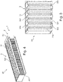
Die Haltevorrichtung 30 weist eine Kastenform auf. Die Seite der Haltevorrichtung 30 und damit der Abscheideeinheit 3, die der lonisationseinheit 2 zugewandt ist, wird im Folgenden auch als Vorderseite bezeichnet. Die gegenüberliegende Seite der Haltevorrichtung 30 und damit der Abscheideeinheit 3 wird auch als Rückseite bezeichnet. Die Haltevorrichtung 30 ist nach vorne und nach hinten offen. Insbesondere besteht die Haltevorrichtung 30 aus einer ersten Begrenzungswand 300 und einer zweiten Begrenzungswand 301, die parallel zueinander liegen und die Oberseite und Unterseite der Haltevorrichtung 30 bilden. Zwischen den Begrenzungswänden 300, 301 verlaufen senkrecht zu den Begrenzungswänden 300, 301 stehende Rahmenstege 303. Die Rahmenstege 303 erstrecken sich von der Vorderseite zu der Rückseite der Haltevorrichtung 30 parallel zueinander und weisen eine geringe Materialstärke auf. Zwischen zwei benachbarten Rahmenstegen 303 ist jeweils ein Aufnahmeraum 302 gebildet. An dem seitlichen Rand der Begrenzungswänden 300, 301 weist die Haltevorrichtung 30 in der dargestellten Ausführungsform eine Seitenwand 307 auf, die parallel zu den Rahmenstegen 303 liegt aber eine größere Materialstärke als die Rahmenstege 303 aufweist.The holding
In der dargestellten Ausführungsform sind in der ersten Begrenzungswand 300, die im Folgenden auch als Oberseite der Haltevorrichtung 30 bezeichnet wird, Durchgangsschlitze 304 eingebracht. Die Durchgangsschlitze 304 erstrecken sich in der Tiefenrichtung der Begrenzungswand 300, das heißt in der Richtung von der Vorderseite zu der Rückseite der Haltevorrichtung 30. Die Durchgangsschlitze 304 verlaufen parallel zueinander. Wie sich aus der
Wie sich aus
An der Rückseite der Haltevorrichtung 30 ist ein Abdeckrahmen 309 vorgesehen. Durch den Abdeckrahmen 309 ist an der Rückseite der Begrenzungswände 300, 301 eine Strebe 308 gebildet. Durch diese Strebe 308 werden die Durchgangsschlitze 304 nach hinten verschlossen. Der Abdeckrahmen 309 kann einteilig mit den Begrenzungswänden 300, 301 ausgebildet sein. Insbesondere kann die Strebe 308 durch das Einbringen der Durchgangsschlitze 304 in die obere Begrenzungswand 300 gebildet werden.A
Wie sich aus
In der ersten Ausführungsform der Haltevorrichtung 30 kann diese auch als Spannrahmen für eine Abscheideelektrode 31 bezeichnet werden, die einen flachen Leiter darstellt, welcher mindestens an den Berührungsstellen mit der Haltevorrichtung 30, vorzugsweise jedoch vollständig isoliert ist.In the first embodiment of the holding
Unter Bezugnahme auf
Dieser Verlauf der Abscheideelektrode 31 setzt sich bis zu der Seite der Haltevorrichtung 30 fort, die der Seite an der das erste Ende der Abscheideelektrode 31 liegt, gegenüber liegt. In der dargestellten Ausführungsform ist an dieser Seite der Haltevorrichtung 30 ein Kontaktraum 4 angeordnet. Dieser kann durch nichtleitende Vergußmasse an der Haltevorrichtung 30 ausgebildet sein. In den Kontaktraum 4 wird das zweite Ende der Abscheideelektrode 31 eingeführt und kann dort mit einer Hochspannungseinheit (nicht gezeigt) verbunden werden.This course of the separating
An den Auflagestellen der Abscheideelektrode 31 auf der Haltevorrichtung 30, insbesondere auf der ersten und zweiten Begrenzungswand 300, 301 zwischen den Durchgangsschlitzen 304 ist das Material der Begrenzungswand 300, 301 gerundet. Der Radius der Abrundung wird insbesondere durch den zulässigen Knickradius einer Isolationsbeschichtung auf der Abscheideelektrode 31 bestimmt.The material of the
Das Einbringen der Abscheideelektrode 31 kann durch Einfädeln des flachen Leiters in der beschriebenen Art erfolgen. Hierbei kann vorzugsweise eine Führungsvorrichtung (nicht gezeigt) von der Vorderseite oder Rückseite in die Aufnahmeräume 302 eingebracht werden, die diese bis auf einen Spalt, durch den die Abscheideelektrode 31 geführt werden soll, ausfüllt.The
Alternativ zum Einfädeln ist es auch möglich, dass die Abscheideeinheit in die in den
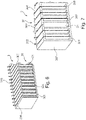
In den
Die zweite Ausführungsform unterscheidet sich von der in den
Wie auch bei der ersten Ausführungsform weist die Haltevorrichtung 30 bei der zweiten Ausführungsform eine Kastenform auf. Die Haltevorrichtung 30 ist nach vorne und nach hinten offen. Insbesondere besteht die Haltevorrichtung 30 aus einer ersten Begrenzungswand 300 und einer zweiten Begrenzungswand 301, die parallel zueinander liegen und die Oberseite und Unterseite der Haltevorrichtung 30 bilden. Zwischen den Begrenzungswänden 300, 301 verlaufen senkrecht zu den Begrenzungswänden 300, 301 stehende Rahmenstege 303. Die Rahmenstege 303 erstrecken sich von der Vorderseite zu der Rückseite der Haltevorrichtung 30 parallel zueinander und weisen eine geringe Materialstärke auf. Zwischen zwei benachbarten Rahmenstegen 303 ist jeweils ein Aufnahmeraum 302 gebildet.As in the first embodiment, the holding
Im Gegensatz zu der ersten Ausführungsform sind bei der zweiten Ausführungsform in der zweiten Begrenzungswand 301 keine Durchgangsschlitze eingebracht. Stattdessen sind in der Oberseite, der zweiten Begrenzungswand 301, das heißt der Seite der zweiten Begrenzungswand 301, die der ersten Begrenzungswand 301 zugewandt ist, Führungsnuten 305 eingebracht. Die Führungsnuten 305 sind so positioniert, dass diese mit den Durchgangsschlitz 304 in der ersten Begrenzungswand 300 ausgerichtet sind, das heißt senkrecht unterhalb der Durchgangsschlitz 304 liegen.In contrast to the first embodiment, no through-slots are made in the
In der Haltevorrichtung 30 sind in der zweiten Ausführungsform Abscheideelektroden 31 eingebracht, die jeweils eine Platte darstellen. An jeder der Abscheideelektroden 31 ist am oberen Rand ein Kontaktiervorsprung 310 vorgesehen. Jede Abscheideelektroden 31 ist von oben durch einen Durchgangsschlitz 304 in der ersten Begrenzungswand 300 geführt und erstreckt sich durch den Aufnahmeraum 302 im Inneren der Haltevorrichtung 30. Der untere Rand der Abscheideelektrode 31 ist in der Führungsnut 305 aufgenommen. Die Kontaktiervorsprünge 310 stehen über die Oberseite der ersten Begrenzungswand 300 über und können so mit Kontaktmitteln, beispielsweise einer Schiene verbunden werden.In the second embodiment,
Auch bei der zweiten Ausführungsform kann die Haltevorrichtung 30 einteilig oder zweiteilig sein. Insbesondere können die Begrenzungswände 300, 301 und die Rahmenstege 303 bis zu einem Ende der Durchgangsschlitze 304 in der ersten Begrenzungswand 300 als ein Teil ausgebildet sein. An dieses Teil kann dann ein als Abdeckrahmen (nicht gezeigt) weiteres Teil angebracht werden und so die Durchgangsschlitze 304 begrenzt werden.In the second embodiment, too, the holding
Die Abscheideelektroden 31 sind bei den beiden gezeigten Ausführungsformen vorzugsweise jeweils mit einer isolierenden Beschichtung (nicht gezeigt) versehen.In the two embodiments shown, the
Die Erfindung wird im Folgenden erneut allgemein beschrieben. Ein zu reinigendes Fluid, das insbesondere Luft darstellt, fließt beziehungsweise strömt durch die erfindungsgemäße elektrostatische Filtereinheit, die auch als elektrostatischer Filter bezeichnet werden kann. Die Strömung wird vorzugsweise durch ein Gebläse einer Lüftungsvorrichtung, an der die Filtereinheit vorgesehen ist, bewirkt. Dabei werden Partikel in dem Fluid zunächst innerhalb einer lonisationseinheit elektrisch geladen und später in einer Abscheideeinheit abgeschieden. Die Abscheideeinheit zeichnet sich dadurch aus, dass sie ein möglichst homogenes elektrisches Feld beinhaltet. Auf die geladenen Partikel wirkt während des Passierens aufgrund ihrer Ladung parallel zu den Feldlinien der Abscheidung die elektrische Feldkraft (F). Die resultierende Beschleunigung lenkt die Partikel von ihrer Bahn aus und sie treffen nach einer diskreten Zeit t die Niederschlagselektroden. Mit diesem Auftreffen gelten die Partikel als abgeschieden. Prinzipbedingt wird die Effizienz der Abscheidung maximal, wenn die Verweilzeit der Partikel größer ist als der maximale Auslegungsweg s.The invention is again generally described below. A fluid to be cleaned, which is in particular air, flows or streams through the electrostatic filter unit according to the invention, which can also be referred to as an electrostatic filter. The flow is preferably effected by a fan of a ventilation device on which the filter unit is provided. In this case, particles in the fluid are initially electrically charged within an ionization unit and later separated out in a separation unit. The separating unit is characterized by the fact that it contains an electrical field that is as homogeneous as possible. The electric field force (F) acts on the charged particles as they pass due to their charge parallel to the field lines of the deposition. The resulting acceleration deflects the particles from their path and after a discrete time t they hit the collecting electrodes. With this impact, the particles are considered separated. Due to the principle, the efficiency of the separation is at its maximum when the dwell time of the particles is greater than the maximum design path s.
Die erfindungsgemäße elektrostatische Filtereinheit kann zur Filterung von Partikeln und Luftverunreinigungen bis in den Feinstaubbereich 1µm verwendet werden. Die erfindungsgemäße Filtereinheit ist dabei nach Fertigungsaspekten, Kosten und Performancetechnischen Aspekten optimiert.The electrostatic filter unit according to the invention can be used to filter particles and air pollution down to the fine dust range of 1 μm. the filter unit according to the invention is optimized according to manufacturing aspects, costs and performance aspects.
Die Niederschlagselektroden der Abscheideeinheit stellen eine Versperrung des passierenden Fluidvolumenstroms dar. Durch die Versperrung nimmt die Fluidgeschwindigkeit linear zur Versperrung zu. Dies ist gleichbedeutend einer Reduktion der Verweilzeit t. Heutige elektrostatische Filter kompensieren diese Verluste mit einer Verlängerung der Abscheideeinheit, um die Verweilzeit zu vergrößern. Gleichzeitig steigt der Druckverlust an der Abscheideeinheit mit der Erhöhung der Geschwindigkeit und der Verlängerung der Abscheideeinheit an. Die Energieeffizienz des Gesamtsystems wird durch eine höhere Versperrung reduziert.The precipitation electrodes of the separating unit represent a blockage of the passing fluid volume flow. Due to the blockage, the fluid speed increases linearly to the blockage. This is equivalent to a reduction in the residence time t. Today's electrostatic filters compensate for these losses by lengthening the separation unit in order to increase the residence time. At the same time, the pressure loss at the separation unit increases with the increase in speed and the lengthening of the separation unit. The energy efficiency of the overall system is reduced by a higher obstruction.
Bei bekannten elektrostatischen Filtern sind meist Arrays/Reihen von Metallplatten, ähnlich einem normalen Plattenkondensators vorgesehen. Die Platten müssen dabei mindestens an ihrer Aufhängung voneinander isoliert angeordnet sein. Je nach Einsatzgebiet und Einsatzbedingungen kann zusätzlich eine vollständig-flächige Isolationsschicht der Elektroden notwendig sein, um Überschläge zu vermeiden. Die Versperrung steigt dadurch an.In known electrostatic filters, arrays/rows of metal plates are usually provided, similar to a normal plate capacitor. The plates must be isolated from each other at least at their suspension point. Depending on the area of application and the conditions of use, an additional, full-surface insulation layer may be necessary for the electrodes in order to prevent flashovers. This increases the blockage.
Zudem sind der konstruktive Aufwand und die Fertigungskosten durch die hohen Teilezahlen und die aufwändige Ausrichtung der Platten hoch.In addition, the design effort and the production costs are high due to the large number of parts and the complex alignment of the plates.
Die vorliegende Erfindung weist diese Nachteile nicht mehr auf beziehungsweise reduziert diese Nachteile zumindest.The present invention no longer has these disadvantages or at least reduces these disadvantages.
Mit der vorliegenden Erfindung wird eine vorzugsweise einteilige jedoch optional auch mehrteilige formschlüssige Haltevorrichtung geschaffen, die auch als Rahmen oder Halterahmen bezeichnet werden kann. Die Haltevorrichtung besteht aus elektrisch leitendem Material und wird in einer Abscheideeinheit in der elektrostatischen Filtereinheit, die auch als elektrostatisches Filtermodul bezeichnet werden kann, eingesetzt. Dabei wird der Rahmen mit der Erde der verbundenen Hochspannungseinheit verbunden. Der Rahmen dient dem Zweck die Abscheideelektroden, die auch als Hochspannungselektroden bezeichnet werden können, aufzunehmen und auszurichten. Der Rahmen selbst weist aufgrund einer Vielzahl formschlüssiger Rahmenstege eine hohe mechanische Stabilität auf. Gleichzeitig bildet der Rahmen den Gegenpol zu den Hochspannungselektroden. Um Rahmen und Hochspannungselektrode elektrisch zu trennen kann wahlweise die Abscheideelektrode von einer Isolierung ummantelt sein oder der Rahmen ist entsprechend mit einem Isolator beschichtet.With the present invention, a preferably one-part, but optionally also multi-part, form-fitting holding device is created, which can also be referred to as a frame or holding frame. The holding device consists of electrically conductive material and is used in a separating unit in the electrostatic filter unit, which can also be referred to as an electrostatic filter module. In doing so, the frame is connected to the earth of the connected high-voltage unit. The purpose of the frame is to accommodate and align the deposition electrodes, which can also be referred to as high-voltage electrodes. The frame itself has a high mechanical stability. At the same time, the frame forms the opposite pole to the high-voltage electrodes. In order to separate the frame and the high-voltage electrode electrically, the separating electrode can optionally be encased in insulation or the frame can be appropriately coated with an insulator.
Optional können an der Einströmseite, das heißt der Vorderseite, der Haltevorrichtung die Gegenelektroden der notwendigen lonisationseinheit mit angebracht sein. In dieser Konfiguration ist der Installationsaufwand der lonisationseinheit weiter reduziert. Einzig Drahtaufnahmen und die Kontaktierung zur Hochspannungskomponente müssen zusätzlich zu der Haltevorrichtung geschaffen werden.Optionally, the counter-electrodes of the required ionization unit can also be attached to the inflow side, ie the front side, of the holding device. In this configuration, the effort involved in installing the ionization unit is further reduced. The only things that have to be created in addition to the holding device are wire receptacles and the contact to the high-voltage component.
Vorzugsweise werden das Abscheidepaket bestehend aus Haltevorrichtung und Abscheideelektrode(n) sowie die lonisationseinheit in einem isolierten Außengehäuse integriert.The separating package consisting of the holding device and separating electrode(s) and the ionization unit are preferably integrated in an insulated outer housing.
Da bei der erfindungsgemäßen Filtereinheit die Haltevorrichtung selbst an die Erde der Hochspannungsquelle angeschlossen wird, werden die Anzahl notwendiger Bauteile und gleichzeitig die Anzahl an Montageschritten verringert.In the filter unit according to the invention, since the holding device itself is connected to the ground of the high-voltage power source, the number of necessary components is reduced and, at the same time, the number of assembly steps is reduced.
Bei der Ausführungsform der Filtereinheit, bei der eine einzige Abscheideelektrode, insbesondere ein positiver flacher Leiter, verwendet wird und beispielsweise in die Haltevorrichtung eingefädelt ist, reduziert sich die Anzahl der notwendigen Kontaktierungen weiter. Abgesehen von der Spannungsversorgung der Hochspannungseinheit müssen in der Filtereinheit dann nur noch zwei Kontaktierungen verbaut werden. Die Haltevorrichtung muss an die Erde und die der flexible Abscheideelektrode an den positiven Ausgang der Hochspannungseinheit angeschlossen werden. Diese Kontaktierung ist einfacher als bei bekannten Filtereinheiten, bei denen alle als Platten ausgestalteten Niederschlagselektroden, das heißt Abscheideelektroden und Gegenelektroden, zueinander über Schienen oder durchgehende Kabel in Reihe verbunden und dann an die Hochspannungseinheit angeschlossen werden müssen.In the embodiment of the filter unit in which a single separation electrode, in particular a positive flat conductor, is used and is threaded into the holding device, for example, the number of necessary contacts is further reduced. Apart from the power supply for the high-voltage unit, only two contacts then have to be installed in the filter unit. The fixture must be connected to earth and the flexible separator electrode to the positive output of the high voltage unit. This contacting is simpler than in known filter units, in which all collecting electrodes designed as plates, ie separating electrodes and counter-electrodes, must be connected in series to one another via rails or continuous cables and then connected to the high-voltage unit.
Bei der Ausführungsform der Filtereinheit, bei der nur einseitige Durchgangsschlitze und vorzugsweise Führungsnuten gegenüberliegend vorgesehen sind, reduziert sich die Anzahl an Elektroden-Platten der Abscheideeinheit gegenüber den bekannten Filtereinheiten um die Hälfte, da die Haltevorrichtung mit den Rahmenstreben die Gegenelektroden bildet, die Rahmenstreben aber nicht mehr einzeln eingebracht und kontaktiert werden müssen. Lediglich die Abscheideelektroden, die als Platten ausgestaltet sind, müssen weiterhin in Reihe kontaktiert werden und an die Hochspannungsversorgung angeschlossen werden. Der Vorteil dieser Ausführungsform liegt in der reduzierten Anzahl an Bauteilen für die Abscheideeinheit um 50%. Das Einbringen der noch notwendigen Platte erfolgt einseitig und ist daher fertigungstechnisch gut handhabbar.In the embodiment of the filter unit in which only one-sided through-slots and preferably guide grooves are provided opposite one another, the number of electrode plates of the separating unit is reduced compared to the known ones Filter units by half, since the holding device with the frame struts forms the counter-electrodes, but the frame struts no longer have to be inserted and contacted individually. Only the deposition electrodes, which are designed as plates, still have to be contacted in series and connected to the high-voltage supply. The advantage of this embodiment lies in the reduced number of components for the separating unit by 50%. The insertion of the plate that is still required is carried out on one side and is therefore easy to handle in terms of production technology.
Durch die formschlüssige Verbindung der Haltevorrichtung, insbesondere der ersten und zweiten Begrenzungswand durch die Rahmenstege ergibt sich außerdem eine enorme mechanische Stabilität und die Geometrie weist Vorteile bei der Herstellung mittels Spritzguß (leitfähige Kunststoffe, Aluminium, u.a.) auf, da durch den Formschluss der Verzug vermindert wird.The form-fitting connection of the holding device, in particular the first and second boundary wall through the frame webs, also results in enormous mechanical stability and the geometry has advantages in production using injection molding (conductive plastics, aluminum, etc.), since the form-fitting connection reduces distortion becomes.
- 11
- Filtereinheitfilter unit
- 1010
- Schutzgitterprotective grid
- 22
- lonisationseinheitionization unit
- 2020
- Gegenelektrodecounter electrode
- 33
- Abscheideeinheitseparation unit
- 3030
- Haltevorrichtungholding device
- 300300
- erste Begrenzungswandfirst boundary wall
- 301301
- zweite Begrenzungswandsecond boundary wall
- 302302
- Aufnahmeraumrecording room
- 303303
- Rahmenstegframe bridge
- 304304
- Durchgangsschlitzthrough slot
- 305305
- Führungsnutguide groove
- 306306
- Verlängerungrenewal
- 307307
- SeitenwandSide wall
- 308308
- Strebestrut
- 309309
- Abdeckrahmencover frame
- 3131
- Abscheideelektrodedeposition electrode
- 310310
- Kontaktiervorsprungcontact projection
- 44
- Kontaktraumcontact space
- 55
- Lüftungsvorrichtungventilation device
- 5050
- Lüftungsgehäuseventilation housing
- 5151
- Prallplatteflapper
- 5252
- Ansaugöffnungintake port
- 66
- Kochfeldhob
- SS
- Strömungsrichtungflow direction
Claims (17)
- Electrostatic filter unit for a ventilation housing (5) comprising an ionisation unit (2) and a precipitation unit (3) having at least one precipitation electrode (31), wherein the precipitation unit (3) has a holding apparatus (30) for holding the at least one precipitation electrode (31), the holding apparatus (30) has a guiding geometry for the at least one precipitation electrode (31), and the holding apparatus (30) consists of an electrically conductive material, characterised in that the holding apparatus (30) comprises a first and a second delimiting wall (300, 301) and at least two frame webs (303) that lie between the first and the second delimiting wall (300, 301), that in each case a receiving compartment (302) for at least one part of a precipitation electrode (31) is formed between two adjacent frame webs (303) and that the guiding geometry has at least one through-slot (304) for a precipitation electrode (31) through one of the delimiting walls (300, 301).
- Electrostatic filter unit according to claim 1, characterised in that the frame webs (303) extend parallel to one another in a perpendicular manner with respect to the first and second delimiting wall (300, 301) of the holding apparatus (30) and that the at least one through-slot (304) of the guiding geometry is provided in each case between two frame webs (303) in one of the delimiting walls (300, 301).
- Electrostatic filter unit according to one of claims 1 or 2, characterised in that at least one through-slot (304) is provided in the first delimiting wall (300) and likewise at least one through-slot (304) that is aligned with the at least one through-slot (304) in the first delimiting wall (300) is provided in the second delimiting wall (301).
- Electrostatic filter unit according to one of claims 1 to 3, characterised in that the edges of the at least one through-slot (304) are rounded.
- Electrostatic filter unit according to one of claims 1 to 4, characterised in that the precipitation electrode (31) is formed by a band that extends through at least two receiving compartments (302) of the holding apparatus (30) in a perpendicular manner with respect to the first and second delimiting wall (300, 301).
- Electrostatic filter unit according to claim 5, characterised in that the precipitation electrode (31) is a preformed component and has a meandering shape.
- Electrostatic filter unit according to one of claims 1 to 6, characterised in that at least one through-slot (304) is provided in the first delimiting wall (300) and at least one guiding groove (305) that is aligned with the through-slot (304) of the first delimiting wall (300) is provided in the second delimiting wall (301).
- Electrostatic filter unit according to one of claims 1 to 4, characterised in that the at least one precipitation electrode (31) is a planar plate and a precipitation electrode (31) is received at least in part in each receiving compartment (302).
- Electrostatic filter unit according to one of claims 1 to 8, characterised in that the at least one precipitation electrode (31) is insulated over its entire surface apart from a contact region for making contact with a high voltage unit.
- Electrostatic filter unit according to one of claims 8 or 9, characterised in that the at least one precipitation electrode (31) has as a contact region a contact protrusion (310) that protrudes outwards beyond the delimiting wall (300, 301) in which the at least one through-slot (304) is provided.
- Electrostatic filter unit according to one of claims 1 to 10, characterised in that the holding apparatus (30) is insulated.
- Electrostatic filter unit according to one of claims 1 to 11, characterised in that the at least one through-slot (304) terminates at a spacing with respect to the front side and rear side of the holding apparatus (30).
- Electrostatic filter unit according to one of claims 1 to 12, characterised in that the holding apparatus (30) is constructed in two parts wherein one part comprises the delimiting walls (300, 301) having the provided guiding geometry and a further part represents a cover frame (309) that closes the guiding geometry to the front or to the rear.
- Electrostatic filter unit according to one of claims 1 to 13, characterised in that in each case a plate-shaped extension (306) is arranged on the holding apparatus (30) on the front side of the first and the second delimiting wall (300, 301) and the plate-shaped extensions in each case extend into the ionisation unit (2) and form the counter electrodes of the ionisation unit (2).
- Electrostatic filter unit according to one of claims 1 to 14, characterised in that the holding apparatus (30) has on a lateral edge of the delimiting walls (300, 301) a contact space (4) for contacting the at least one precipitation electrode (31) that consists of a non-conductive material.
- Electrostatic filter unit according to one of claims 1 to 15, characterised in that the holding apparatus (30) is produced by an injection moulding method.
- Ventilation apparatus characterised in that this comprises at least one electrostatic filter unit (1) according to one of claims 1 to 16.
Applications Claiming Priority (1)
| Application Number | Priority Date | Filing Date | Title |
|---|---|---|---|
| DE102018205333.2A DE102018205333A1 (en) | 2018-04-10 | 2018-04-10 | Electrostatic filter unit and ventilation unit with electrostatic filter unit |
Publications (2)
| Publication Number | Publication Date |
|---|---|
| EP3552711A1 EP3552711A1 (en) | 2019-10-16 |
| EP3552711B1 true EP3552711B1 (en) | 2022-06-15 |
Family
ID=65818332
Family Applications (1)
| Application Number | Title | Priority Date | Filing Date |
|---|---|---|---|
| EP19163448.4A Active EP3552711B1 (en) | 2018-04-10 | 2019-03-18 | Electrostatic filter unit and ventilation device with electrostatic filter unit |
Country Status (3)
| Country | Link |
|---|---|
| EP (1) | EP3552711B1 (en) |
| CN (1) | CN110354995B (en) |
| DE (1) | DE102018205333A1 (en) |
Family Cites Families (36)
| Publication number | Priority date | Publication date | Assignee | Title |
|---|---|---|---|---|
| CH306042A (en) * | 1952-07-18 | 1955-03-31 | Sfindex | Apparatus for the electrostatic separation of solid and liquid foreign particles from a gas flow. |
| DE6602548U (en) * | 1958-02-21 | 1969-05-29 | Messen Jaschin G | ELECTROSTATIC FILTER |
| US3027970A (en) * | 1959-01-26 | 1962-04-03 | Honeywell Regulator Co | Fluid cleaning apparatus |
| US3729815A (en) * | 1971-01-25 | 1973-05-01 | Koppers Co Inc | Method for installing multiples of dust collector plates |
| US3892545A (en) * | 1971-05-12 | 1975-07-01 | Svenska Flaektfabriken Ab | Arrangement for suspending and controlling precipitation electrodes |
| US3778970A (en) * | 1971-06-11 | 1973-12-18 | Air King Corp | Electrostatic air cleaner |
| DE2146288A1 (en) * | 1971-09-16 | 1973-03-22 | Bosch Hausgeraete Gmbh | KITCHEN EXTRACTOR HOOD FOR SEPARATING EVAPS AND POLLUTIONS FROM THE ROOM AIR |
| JPS5437502Y2 (en) * | 1975-07-19 | 1979-11-09 | ||
| SE401327B (en) * | 1976-04-09 | 1978-05-02 | Elfi Elektrofilter Ab | ELECTRIC FILTER FOR AIR TRAINING |
| DE2620510A1 (en) * | 1976-05-08 | 1977-11-24 | Miele & Cie | Electrostatic air filter - with filter plates mounted on a removable pair of plate holders forming a unit |
| JPS5735755U (en) * | 1980-07-28 | 1982-02-25 | ||
| US4747856A (en) * | 1987-08-21 | 1988-05-31 | General Electric Environmental Services, Inc. | Lower end alignment device for electrostatic precipitator collector electrodes |
| JPH0645017B2 (en) * | 1988-12-27 | 1994-06-15 | ダイキン工業株式会社 | Electric dust collector |
| DE3915639C1 (en) * | 1989-05-12 | 1991-01-24 | Boehler Abfall-Abluft-Abwasser-Umweltschutz Ges.M.B.H., Feldkirch, At | |
| JPH0751594A (en) * | 1993-08-17 | 1995-02-28 | Ricoh Elemex Corp | Dust collector in air cleaner |
| JP3328683B2 (en) * | 1993-09-24 | 2002-09-30 | 株式会社安川電機 | Air purifier |
| JP3257271B2 (en) * | 1994-04-04 | 2002-02-18 | ダイキン工業株式会社 | Dust collection part of electric dust collection element |
| JP3970424B2 (en) * | 1997-05-14 | 2007-09-05 | 松下エコシステムズ株式会社 | Electric dust collecting filter and electric dust collecting device equipped with the electric dust collecting filter |
| JP4350180B2 (en) * | 1998-04-15 | 2009-10-21 | パナソニックエコシステムズ株式会社 | Electric dust collecting filter and manufacturing method thereof |
| JP2000015138A (en) * | 1998-07-06 | 2000-01-18 | Tokai Rubber Ind Ltd | Dust collecting unit of air cleaner |
| JP4156141B2 (en) * | 1999-08-31 | 2008-09-24 | 松下エコシステムズ株式会社 | Electric dust filter |
| JP4910339B2 (en) * | 2005-01-07 | 2012-04-04 | パナソニック株式会社 | Dust collector and air conditioner |
| US7438742B2 (en) * | 2006-02-21 | 2008-10-21 | Alstom Technology Ltd | Method and apparatus for preventing wear in an electrostatic precipitator |
| JP2007253055A (en) * | 2006-03-23 | 2007-10-04 | Matsushita Electric Ind Co Ltd | Dust collector and air-conditioning equipment |
| JP2008140567A (en) * | 2006-11-30 | 2008-06-19 | Nittetsu Mining Co Ltd | Gas excitation device having contact type suspension electrode, and gas excitation method |
| DE102008062415A1 (en) * | 2008-12-17 | 2010-07-01 | Langner, Manfred H. | Ionization device for air treatment plants |
| CN202555401U (en) * | 2012-03-16 | 2012-11-28 | 原皓 | Closed moving strip-shaped duct-collecting anode device for electrostatic dust collector |
| CN103008107B (en) * | 2012-09-14 | 2016-01-06 | 武汉工程大学 | Continuous winding moves control of dust plate type electrostatic dust removal machine |
| JP2014079700A (en) * | 2012-10-16 | 2014-05-08 | Yasuo Teratani | Air decontamination machine |
| SG11201601197UA (en) * | 2013-09-02 | 2016-03-30 | Creative Tech Corp | Particle collector system and dust collection method |
| CN103949343B (en) * | 2014-05-08 | 2018-05-22 | 汉王科技股份有限公司 | Air cleaning unit |
| CN204051909U (en) * | 2014-06-22 | 2014-12-31 | 郭绍华 | A kind of toward overlying electrode electrostatic precipitation unit |
| JP6620994B2 (en) * | 2014-08-18 | 2019-12-18 | 株式会社クリエイティブテクノロジー | Dust collector |
| EP3093564B1 (en) * | 2015-05-12 | 2018-09-19 | Blueair AB | Air cleaning device |
| CN106944260B (en) * | 2015-10-30 | 2020-02-07 | Lg电子株式会社 | Electric dust collector and its manufacturing method |
| CN106196556A (en) * | 2016-08-30 | 2016-12-07 | 冯肇霖 | A kind of multifunctional air purifying module and its implementation |
-
2018
- 2018-04-10 DE DE102018205333.2A patent/DE102018205333A1/en not_active Withdrawn
-
2019
- 2019-03-18 EP EP19163448.4A patent/EP3552711B1/en active Active
- 2019-04-09 CN CN201910280002.3A patent/CN110354995B/en active Active
Also Published As
| Publication number | Publication date |
|---|---|
| CN110354995A (en) | 2019-10-22 |
| CN110354995B (en) | 2022-11-29 |
| DE102018205333A1 (en) | 2019-10-10 |
| EP3552711A1 (en) | 2019-10-16 |
Similar Documents
| Publication | Publication Date | Title |
|---|---|---|
| DE102007025416B3 (en) | Method and apparatus for separating contaminants from a gas stream | |
| DE3237780C2 (en) | ||
| EP3552710A1 (en) | Electrostatic filter unit and ventilation device with electrostatic filter unit | |
| CH625974A5 (en) | ||
| EP3596396A1 (en) | Filter unit for an extractor hood, and extractor hood | |
| DE202015000607U1 (en) | System for electric particle charging | |
| DE102011053578A1 (en) | Counter electrode for use in device for separating contaminations e.g. oil droplets, from intake air supplied to combustion engine, has outer surface with material transmissive for part of contaminations separated from gas flow | |
| DE3804779A1 (en) | Device for removing soot particles from the exhaust gas stream of a diesel internal combustion engine | |
| EP3376117B1 (en) | Filter unit for extractor hood and extractor hood | |
| EP3552711B1 (en) | Electrostatic filter unit and ventilation device with electrostatic filter unit | |
| WO2023012166A1 (en) | Air filter comprising an electrostatic precipitator | |
| DE102017214495A1 (en) | Filter unit for air cleaning device and air cleaning device | |
| EP1304760B2 (en) | Storage battery | |
| DE3243079A1 (en) | Switchgear cabinet | |
| EP0345309A1 (en) | Electrostatic filter for continuous separation of solid or liquid particles suspended in a gas stream | |
| WO2010091694A1 (en) | Electrostatic air cleaner | |
| EP3517208A1 (en) | Filter unit for air purification device | |
| DE3151936A1 (en) | PLATE ELECTRODE ARRANGEMENT FOR AN ELECTROSTATIC SEPARATOR | |
| EP4000738B1 (en) | Filter for cleaning a gas flow | |
| DE19742433C1 (en) | Ventilation filter plate for use in electrical switchgear housings | |
| CH566171A5 (en) | Disposable electrofilter has simple bent lug contacts - between positive plates bypassing negative plates through openings and vice versa | |
| WO2008071630A1 (en) | Electrostatic particle separator | |
| DE102007063197A1 (en) | Solar cell structure, particularly for photovoltaic, for application at basic building structure, such as roof or wall, has cover plate arranged opposite to multiple carrier plates | |
| DE2462288A1 (en) | Electric precipitator with one front plate at each end - earthed plate carries rods in conductive, other in insulated connections | |
| DE112020000389T5 (en) | DUST COLLECTING DEVICE FOR ELECTRIC SEPARATORS |
Legal Events
| Date | Code | Title | Description |
|---|---|---|---|
| PUAI | Public reference made under article 153(3) epc to a published international application that has entered the european phase |
Free format text: ORIGINAL CODE: 0009012 |
|
| STAA | Information on the status of an ep patent application or granted ep patent |
Free format text: STATUS: THE APPLICATION HAS BEEN PUBLISHED |
|
| AK | Designated contracting states |
Kind code of ref document: A1 Designated state(s): AL AT BE BG CH CY CZ DE DK EE ES FI FR GB GR HR HU IE IS IT LI LT LU LV MC MK MT NL NO PL PT RO RS SE SI SK SM TR |
|
| AX | Request for extension of the european patent |
Extension state: BA ME |
|
| STAA | Information on the status of an ep patent application or granted ep patent |
Free format text: STATUS: REQUEST FOR EXAMINATION WAS MADE |
|
| 17P | Request for examination filed |
Effective date: 20200416 |
|
| RBV | Designated contracting states (corrected) |
Designated state(s): AL AT BE BG CH CY CZ DE DK EE ES FI FR GB GR HR HU IE IS IT LI LT LU LV MC MK MT NL NO PL PT RO RS SE SI SK SM TR |
|
| GRAP | Despatch of communication of intention to grant a patent |
Free format text: ORIGINAL CODE: EPIDOSNIGR1 |
|
| STAA | Information on the status of an ep patent application or granted ep patent |
Free format text: STATUS: GRANT OF PATENT IS INTENDED |
|
| INTG | Intention to grant announced |
Effective date: 20220204 |
|
| GRAS | Grant fee paid |
Free format text: ORIGINAL CODE: EPIDOSNIGR3 |
|
| GRAA | (expected) grant |
Free format text: ORIGINAL CODE: 0009210 |
|
| STAA | Information on the status of an ep patent application or granted ep patent |
Free format text: STATUS: THE PATENT HAS BEEN GRANTED |
|
| AK | Designated contracting states |
Kind code of ref document: B1 Designated state(s): AL AT BE BG CH CY CZ DE DK EE ES FI FR GB GR HR HU IE IS IT LI LT LU LV MC MK MT NL NO PL PT RO RS SE SI SK SM TR |
|
| REG | Reference to a national code |
Ref country code: CH Ref legal event code: EP Ref country code: GB Ref legal event code: FG4D Free format text: NOT ENGLISH |
|
| REG | Reference to a national code |
Ref country code: NL Ref legal event code: FP |
|
| REG | Reference to a national code |
Ref country code: IE Ref legal event code: FG4D Free format text: LANGUAGE OF EP DOCUMENT: GERMAN |
|
| REG | Reference to a national code |
Ref country code: DE Ref legal event code: R096 Ref document number: 502019004619 Country of ref document: DE |
|
| REG | Reference to a national code |
Ref country code: AT Ref legal event code: REF Ref document number: 1498032 Country of ref document: AT Kind code of ref document: T Effective date: 20220715 |
|
| REG | Reference to a national code |
Ref country code: LT Ref legal event code: MG9D |
|
| PG25 | Lapsed in a contracting state [announced via postgrant information from national office to epo] |
Ref country code: SE Free format text: LAPSE BECAUSE OF FAILURE TO SUBMIT A TRANSLATION OF THE DESCRIPTION OR TO PAY THE FEE WITHIN THE PRESCRIBED TIME-LIMIT Effective date: 20220615 Ref country code: NO Free format text: LAPSE BECAUSE OF FAILURE TO SUBMIT A TRANSLATION OF THE DESCRIPTION OR TO PAY THE FEE WITHIN THE PRESCRIBED TIME-LIMIT Effective date: 20220915 Ref country code: LT Free format text: LAPSE BECAUSE OF FAILURE TO SUBMIT A TRANSLATION OF THE DESCRIPTION OR TO PAY THE FEE WITHIN THE PRESCRIBED TIME-LIMIT Effective date: 20220615 Ref country code: HR Free format text: LAPSE BECAUSE OF FAILURE TO SUBMIT A TRANSLATION OF THE DESCRIPTION OR TO PAY THE FEE WITHIN THE PRESCRIBED TIME-LIMIT Effective date: 20220615 Ref country code: GR Free format text: LAPSE BECAUSE OF FAILURE TO SUBMIT A TRANSLATION OF THE DESCRIPTION OR TO PAY THE FEE WITHIN THE PRESCRIBED TIME-LIMIT Effective date: 20220916 Ref country code: FI Free format text: LAPSE BECAUSE OF FAILURE TO SUBMIT A TRANSLATION OF THE DESCRIPTION OR TO PAY THE FEE WITHIN THE PRESCRIBED TIME-LIMIT Effective date: 20220615 Ref country code: BG Free format text: LAPSE BECAUSE OF FAILURE TO SUBMIT A TRANSLATION OF THE DESCRIPTION OR TO PAY THE FEE WITHIN THE PRESCRIBED TIME-LIMIT Effective date: 20220915 |
|
| PG25 | Lapsed in a contracting state [announced via postgrant information from national office to epo] |
Ref country code: RS Free format text: LAPSE BECAUSE OF FAILURE TO SUBMIT A TRANSLATION OF THE DESCRIPTION OR TO PAY THE FEE WITHIN THE PRESCRIBED TIME-LIMIT Effective date: 20220615 Ref country code: LV Free format text: LAPSE BECAUSE OF FAILURE TO SUBMIT A TRANSLATION OF THE DESCRIPTION OR TO PAY THE FEE WITHIN THE PRESCRIBED TIME-LIMIT Effective date: 20220615 |
|
| PG25 | Lapsed in a contracting state [announced via postgrant information from national office to epo] |
Ref country code: SM Free format text: LAPSE BECAUSE OF FAILURE TO SUBMIT A TRANSLATION OF THE DESCRIPTION OR TO PAY THE FEE WITHIN THE PRESCRIBED TIME-LIMIT Effective date: 20220615 Ref country code: SK Free format text: LAPSE BECAUSE OF FAILURE TO SUBMIT A TRANSLATION OF THE DESCRIPTION OR TO PAY THE FEE WITHIN THE PRESCRIBED TIME-LIMIT Effective date: 20220615 Ref country code: RO Free format text: LAPSE BECAUSE OF FAILURE TO SUBMIT A TRANSLATION OF THE DESCRIPTION OR TO PAY THE FEE WITHIN THE PRESCRIBED TIME-LIMIT Effective date: 20220615 Ref country code: PT Free format text: LAPSE BECAUSE OF FAILURE TO SUBMIT A TRANSLATION OF THE DESCRIPTION OR TO PAY THE FEE WITHIN THE PRESCRIBED TIME-LIMIT Effective date: 20221017 Ref country code: ES Free format text: LAPSE BECAUSE OF FAILURE TO SUBMIT A TRANSLATION OF THE DESCRIPTION OR TO PAY THE FEE WITHIN THE PRESCRIBED TIME-LIMIT Effective date: 20220615 Ref country code: EE Free format text: LAPSE BECAUSE OF FAILURE TO SUBMIT A TRANSLATION OF THE DESCRIPTION OR TO PAY THE FEE WITHIN THE PRESCRIBED TIME-LIMIT Effective date: 20220615 Ref country code: CZ Free format text: LAPSE BECAUSE OF FAILURE TO SUBMIT A TRANSLATION OF THE DESCRIPTION OR TO PAY THE FEE WITHIN THE PRESCRIBED TIME-LIMIT Effective date: 20220615 |
|
| PG25 | Lapsed in a contracting state [announced via postgrant information from national office to epo] |
Ref country code: PL Free format text: LAPSE BECAUSE OF FAILURE TO SUBMIT A TRANSLATION OF THE DESCRIPTION OR TO PAY THE FEE WITHIN THE PRESCRIBED TIME-LIMIT Effective date: 20220615 Ref country code: IS Free format text: LAPSE BECAUSE OF FAILURE TO SUBMIT A TRANSLATION OF THE DESCRIPTION OR TO PAY THE FEE WITHIN THE PRESCRIBED TIME-LIMIT Effective date: 20221015 |
|
| REG | Reference to a national code |
Ref country code: DE Ref legal event code: R097 Ref document number: 502019004619 Country of ref document: DE |
|
| PG25 | Lapsed in a contracting state [announced via postgrant information from national office to epo] |
Ref country code: AL Free format text: LAPSE BECAUSE OF FAILURE TO SUBMIT A TRANSLATION OF THE DESCRIPTION OR TO PAY THE FEE WITHIN THE PRESCRIBED TIME-LIMIT Effective date: 20220615 |
|
| PLBE | No opposition filed within time limit |
Free format text: ORIGINAL CODE: 0009261 |
|
| STAA | Information on the status of an ep patent application or granted ep patent |
Free format text: STATUS: NO OPPOSITION FILED WITHIN TIME LIMIT |
|
| PG25 | Lapsed in a contracting state [announced via postgrant information from national office to epo] |
Ref country code: DK Free format text: LAPSE BECAUSE OF FAILURE TO SUBMIT A TRANSLATION OF THE DESCRIPTION OR TO PAY THE FEE WITHIN THE PRESCRIBED TIME-LIMIT Effective date: 20220615 |
|
| 26N | No opposition filed |
Effective date: 20230316 |
|
| PG25 | Lapsed in a contracting state [announced via postgrant information from national office to epo] |
Ref country code: SI Free format text: LAPSE BECAUSE OF FAILURE TO SUBMIT A TRANSLATION OF THE DESCRIPTION OR TO PAY THE FEE WITHIN THE PRESCRIBED TIME-LIMIT Effective date: 20220615 |
|
| PGFP | Annual fee paid to national office [announced via postgrant information from national office to epo] |
Ref country code: DE Payment date: 20230331 Year of fee payment: 5 Ref country code: BE Payment date: 20230321 Year of fee payment: 5 |
|
| PGFP | Annual fee paid to national office [announced via postgrant information from national office to epo] |
Ref country code: NL Payment date: 20230322 Year of fee payment: 5 |
|
| PG25 | Lapsed in a contracting state [announced via postgrant information from national office to epo] |
Ref country code: MC Free format text: LAPSE BECAUSE OF FAILURE TO SUBMIT A TRANSLATION OF THE DESCRIPTION OR TO PAY THE FEE WITHIN THE PRESCRIBED TIME-LIMIT Effective date: 20220615 |
|
| REG | Reference to a national code |
Ref country code: CH Ref legal event code: PL |
|
| GBPC | Gb: european patent ceased through non-payment of renewal fee |
Effective date: 20230318 |
|
| PG25 | Lapsed in a contracting state [announced via postgrant information from national office to epo] |
Ref country code: LU Free format text: LAPSE BECAUSE OF NON-PAYMENT OF DUE FEES Effective date: 20230318 |
|
| REG | Reference to a national code |
Ref country code: IE Ref legal event code: MM4A |
|
| PG25 | Lapsed in a contracting state [announced via postgrant information from national office to epo] |
Ref country code: GB Free format text: LAPSE BECAUSE OF NON-PAYMENT OF DUE FEES Effective date: 20230318 |
|
| PG25 | Lapsed in a contracting state [announced via postgrant information from national office to epo] |
Ref country code: LI Free format text: LAPSE BECAUSE OF NON-PAYMENT OF DUE FEES Effective date: 20230331 Ref country code: IT Free format text: LAPSE BECAUSE OF FAILURE TO SUBMIT A TRANSLATION OF THE DESCRIPTION OR TO PAY THE FEE WITHIN THE PRESCRIBED TIME-LIMIT Effective date: 20220615 Ref country code: IE Free format text: LAPSE BECAUSE OF NON-PAYMENT OF DUE FEES Effective date: 20230318 Ref country code: GB Free format text: LAPSE BECAUSE OF NON-PAYMENT OF DUE FEES Effective date: 20230318 Ref country code: FR Free format text: LAPSE BECAUSE OF NON-PAYMENT OF DUE FEES Effective date: 20230331 Ref country code: CH Free format text: LAPSE BECAUSE OF NON-PAYMENT OF DUE FEES Effective date: 20230331 |
|
| PGFP | Annual fee paid to national office [announced via postgrant information from national office to epo] |
Ref country code: NL Payment date: 20240320 Year of fee payment: 6 |