EP3552698B1 - Kohlenstoffkatalysator und elektrode und batterie damit - Google Patents
Kohlenstoffkatalysator und elektrode und batterie damit Download PDFInfo
- Publication number
- EP3552698B1 EP3552698B1 EP17878288.4A EP17878288A EP3552698B1 EP 3552698 B1 EP3552698 B1 EP 3552698B1 EP 17878288 A EP17878288 A EP 17878288A EP 3552698 B1 EP3552698 B1 EP 3552698B1
- Authority
- EP
- European Patent Office
- Prior art keywords
- peak
- catalyst
- carbon catalyst
- present
- electrode
- Prior art date
- Legal status (The legal status is an assumption and is not a legal conclusion. Google has not performed a legal analysis and makes no representation as to the accuracy of the status listed.)
- Active
Links
Images


Classifications
-
- H—ELECTRICITY
- H01—ELECTRIC ELEMENTS
- H01M—PROCESSES OR MEANS, e.g. BATTERIES, FOR THE DIRECT CONVERSION OF CHEMICAL ENERGY INTO ELECTRICAL ENERGY
- H01M4/00—Electrodes
- H01M4/86—Inert electrodes with catalytic activity, e.g. for fuel cells
- H01M4/96—Carbon-based electrodes
-
- H—ELECTRICITY
- H01—ELECTRIC ELEMENTS
- H01M—PROCESSES OR MEANS, e.g. BATTERIES, FOR THE DIRECT CONVERSION OF CHEMICAL ENERGY INTO ELECTRICAL ENERGY
- H01M4/00—Electrodes
- H01M4/86—Inert electrodes with catalytic activity, e.g. for fuel cells
- H01M4/90—Selection of catalytic material
-
- B—PERFORMING OPERATIONS; TRANSPORTING
- B01—PHYSICAL OR CHEMICAL PROCESSES OR APPARATUS IN GENERAL
- B01J—CHEMICAL OR PHYSICAL PROCESSES, e.g. CATALYSIS OR COLLOID CHEMISTRY; THEIR RELEVANT APPARATUS
- B01J21/00—Catalysts comprising the elements, oxides, or hydroxides of magnesium, boron, aluminium, carbon, silicon, titanium, zirconium, or hafnium
- B01J21/18—Carbon
-
- B—PERFORMING OPERATIONS; TRANSPORTING
- B01—PHYSICAL OR CHEMICAL PROCESSES OR APPARATUS IN GENERAL
- B01J—CHEMICAL OR PHYSICAL PROCESSES, e.g. CATALYSIS OR COLLOID CHEMISTRY; THEIR RELEVANT APPARATUS
- B01J27/00—Catalysts comprising the elements or compounds of halogens, sulfur, selenium, tellurium, phosphorus or nitrogen; Catalysts comprising carbon compounds
- B01J27/14—Phosphorus; Compounds thereof
- B01J27/185—Phosphorus; Compounds thereof with iron group metals or platinum group metals
-
- H—ELECTRICITY
- H01—ELECTRIC ELEMENTS
- H01M—PROCESSES OR MEANS, e.g. BATTERIES, FOR THE DIRECT CONVERSION OF CHEMICAL ENERGY INTO ELECTRICAL ENERGY
- H01M4/00—Electrodes
- H01M4/86—Inert electrodes with catalytic activity, e.g. for fuel cells
- H01M4/8647—Inert electrodes with catalytic activity, e.g. for fuel cells consisting of more than one material, e.g. consisting of composites
- H01M4/8652—Inert electrodes with catalytic activity, e.g. for fuel cells consisting of more than one material, e.g. consisting of composites as mixture
-
- H—ELECTRICITY
- H01—ELECTRIC ELEMENTS
- H01M—PROCESSES OR MEANS, e.g. BATTERIES, FOR THE DIRECT CONVERSION OF CHEMICAL ENERGY INTO ELECTRICAL ENERGY
- H01M4/00—Electrodes
- H01M4/86—Inert electrodes with catalytic activity, e.g. for fuel cells
- H01M4/90—Selection of catalytic material
- H01M4/9008—Organic or organo-metallic compounds
-
- H—ELECTRICITY
- H01—ELECTRIC ELEMENTS
- H01M—PROCESSES OR MEANS, e.g. BATTERIES, FOR THE DIRECT CONVERSION OF CHEMICAL ENERGY INTO ELECTRICAL ENERGY
- H01M4/00—Electrodes
- H01M4/86—Inert electrodes with catalytic activity, e.g. for fuel cells
- H01M4/90—Selection of catalytic material
- H01M4/9041—Metals or alloys
-
- B—PERFORMING OPERATIONS; TRANSPORTING
- B01—PHYSICAL OR CHEMICAL PROCESSES OR APPARATUS IN GENERAL
- B01J—CHEMICAL OR PHYSICAL PROCESSES, e.g. CATALYSIS OR COLLOID CHEMISTRY; THEIR RELEVANT APPARATUS
- B01J27/00—Catalysts comprising the elements or compounds of halogens, sulfur, selenium, tellurium, phosphorus or nitrogen; Catalysts comprising carbon compounds
- B01J27/14—Phosphorus; Compounds thereof
- B01J27/185—Phosphorus; Compounds thereof with iron group metals or platinum group metals
- B01J27/1853—Phosphorus; Compounds thereof with iron group metals or platinum group metals with iron, cobalt or nickel
-
- B—PERFORMING OPERATIONS; TRANSPORTING
- B01—PHYSICAL OR CHEMICAL PROCESSES OR APPARATUS IN GENERAL
- B01J—CHEMICAL OR PHYSICAL PROCESSES, e.g. CATALYSIS OR COLLOID CHEMISTRY; THEIR RELEVANT APPARATUS
- B01J31/00—Catalysts comprising hydrides, coordination complexes or organic compounds
- B01J31/02—Catalysts comprising hydrides, coordination complexes or organic compounds containing organic compounds or metal hydrides
- B01J31/0234—Nitrogen-, phosphorus-, arsenic- or antimony-containing compounds
- B01J31/0255—Phosphorus containing compounds
- B01J31/0257—Phosphorus acids or phosphorus acid esters
-
- H—ELECTRICITY
- H01—ELECTRIC ELEMENTS
- H01M—PROCESSES OR MEANS, e.g. BATTERIES, FOR THE DIRECT CONVERSION OF CHEMICAL ENERGY INTO ELECTRICAL ENERGY
- H01M12/00—Hybrid cells; Manufacture thereof
- H01M12/04—Hybrid cells; Manufacture thereof composed of a half-cell of the fuel-cell type and of a half-cell of the primary-cell type
- H01M12/06—Hybrid cells; Manufacture thereof composed of a half-cell of the fuel-cell type and of a half-cell of the primary-cell type with one metallic and one gaseous electrode
-
- H—ELECTRICITY
- H01—ELECTRIC ELEMENTS
- H01M—PROCESSES OR MEANS, e.g. BATTERIES, FOR THE DIRECT CONVERSION OF CHEMICAL ENERGY INTO ELECTRICAL ENERGY
- H01M12/00—Hybrid cells; Manufacture thereof
- H01M12/08—Hybrid cells; Manufacture thereof composed of a half-cell of a fuel-cell type and a half-cell of the secondary-cell type
Definitions
- the present invention relates to a carbon catalyst, and an electrode and a battery including the carbon catalyst.
- Patent Literature 1 there is described an oxygen reduction catalyst, including a stack of single-layer graphene and a phosphorous compound, and having such a graphene skeleton that carbon atoms of the graphene are partially replaced by nitrogen atoms, in which the phosphorus compound has a peak of a phosphorus 2p orbital of from 133.0 eV to 134.5 eV in an X-ray photoelectron spectrum, or a peak of a phosphorus 2p orbital of the phosphorus compound is shifted by from 1.0 eV to 2.5 eV toward a high-energy side from a peak of a phosphorus 2p orbital of tetra-n-butylphosphonium bromide in an X-ray photoelectron spectrum.
- Non-Patent Literature 1 describes producing a carbon catalyst that is doped with nitrogen, phosphorus and iron by thermally decomposing polyacrylonitrile nanospheres in the presence of (NH 4 ) 2 HPO 4 and FeCl 3 ⁇ 6H 2 O.
- Non-Patent Literature 2 discloses carbon catalysts for fuel cells comprising iron and phosphorus atoms with a certain ratio of a concentration of phosphorus atoms with respect to a concentration of carbon atoms in X-ray photoelectron spectroscopic measurement.
- the present invention has been made in view of the above-mentioned problem, and one of the objects of the present invention is to provide a carbon catalyst having improved catalytic activity, and an electrode and a battery including the carbon catalyst.
- a carbon catalyst including a metal and phosphorus atoms, wherein the metal is one or more kinds selected from a group consisting of Sc, Ti, V, Cr, Mn, Fe, Co, Ni, Cu, and Zn, wherein the carbon catalyst has a ratio of a concentration (atomic%) of the phosphorus atoms with respect to a concentration (atomic%) of carbon atoms in X-ray photoelectron spectroscopic measurement of 0.0005 or more, the phosphorus atoms exhibiting a peak having a peak top within a range of 132.5 ⁇ 0.3 eV and having a full width at half maximum of 2.0 ⁇ 0.5 eV, which is obtained by peak separation of a phosphorus atom P2p peak.
- the metal is one or more kinds selected from a group consisting of Sc, Ti, V, Cr, Mn, Fe, Co, Ni, Cu, and Zn
- the carbon catalyst has a ratio of a concentration (atomic%) of the phosphorus atoms with respect to a concentration (atomic%) of carbon
- a carbon catalyst having improved catalytic activity is provided.
- the carbon catalyst may have a ratio of an area of the following peak (2) with respect to a total area of the following five peaks (1) to (5) in the X-ray photoelectron spectroscopic measurement of 0.3000 or more, the five peaks being obtained by the peak separation of the phosphorus atom P2p peak: (1) a peak having a peak top within a range of 130.0 ⁇ 0.3 eV and having a full width at half maximum of 2.0 ⁇ 0.5 eV; (2) a peak having a peak top within a range of 132.5 ⁇ 0.3 eV and having a full width at half maximum of 2.0 ⁇ 0.
- the carbon catalyst has a carbon structure in which area ratios (%) of the following two peaks f broad and f narrow obtained by separating a peak in a vicinity of a diffraction angle (2 ⁇ ) of 26° in an X-ray diffraction pattern in powder X-ray diffraction measurement satisfy the following conditions (a) and (b): (a) a peak f broad having a peak top within a range of a diffraction angle (28) of 23.5° ⁇ 3.5° and having a full width at half maximum of 10.0° ⁇ 5.0°: 73.0% or more and less than 100.0%; and (b) a peak f narrow having a peak top within a range of a diffraction angle (20) of 26.5° ⁇ 1.0° and having a full width at half maximum of 3.5° ⁇ 3.0°. more than 0.0% and 27.0% or less.
- area ratios (%) of the following two peaks f broad and f narrow obtained by separating a peak in a vicinity of a dif
- an electrode including any one of the above-mentioned carbon catalysts. According to the embodiment of the present invention, an electrode having improved performance is provided.
- a battery including the above-mentioned electrode. According to the embodiment of the present invention, a battery having improved performance is provided.
- a carbon catalyst having improved catalytic activity, and an electrode and a battery including the carbon catalyst are provided.
- a carbon catalyst according to one embodiment of the present invention includes a metal and phosphorus atoms, where the carbon catalyst has a ratio of a concentration (atomic%) of the phosphorus atoms with respect to a concentration (atomic%) of carbon atoms in X-ray photoelectron spectroscopic measurement of 0.0005 or more, where the phosphorus atoms exhibit a peak having a peak top within a range of 132.5 ⁇ 0.3 eV and having a full width at half maximum of 2.0 ⁇ 0.5 eV, which is obtained by peak separation of a phosphorus atom P2p peak.
- the catalyst of the present invention is a carbon catalyst containing a metal and phosphorus atoms. More specifically, the catalyst of the present invention is a carbonized material containing a metal and phosphorus atoms, which is obtained by carbonizing a raw material containing an organic substance, the metal, and a phosphorus compound as will be described later.
- the metal contained in the catalyst of the present invention is one or more kinds selected from a group consisting of scandium (Sc), titanium (Ti), vanadium (V), chromium (Cr), manganese (Mn), iron (Fe), cobalt (Co), nickel (Ni), copper (Cu), and zinc (Zn).
- the metals belong to the fourth period of Groups III to XII in the periodic table.
- the metal may be preferably one or more kinds selected from a group consisting of Fe, Cu, and Zn.
- a P 132.5 /C ratio is a predetermined threshold value or more, where the P 132.5 /C ratio is a ratio, which is obtained by the XPS measurement, of a concentration (atomic%) of particular phosphorus atoms exhibiting the above-mentioned peak (peak P 132.5 ) having a peak top within a range of 132.5 ⁇ 0.3 eV and having a full width at half maximum of 2.0 ⁇ 0.5 eV with respect to a concentration (atomic%) of carbon atoms.
- the inventors of the present invention have repeatedly conducted extensive investigations on technical means for improving the catalytic activity of a carbon catalyst containing a metal and phosphorus atoms.
- the inventors of the present invention have uniquely found that particular phosphorus atoms exhibiting the above-mentioned peak P 132.5 obtained by peak separation of a phosphorus atom P2p peak in an XPS spectrum contributes to the improvement of the catalytic activity of the carbon catalyst, to thereby achieve the present invention.
- the P2p peak appears within a range of 133 ⁇ 3.3 eV.
- the P2p peak includes peaks of five kinds of phosphorus atoms having different oxidation states due to different binding manners to other atoms.
- the P2p peak can be separated into the following five peaks (1) to (5) by peak separation described later in detail in Examples: (1) a peak (peak P 130.0 ) having a peak top within a range of 130.0 ⁇ 0.3 eV and having a full width at half maximum of 2.0 ⁇ 0.5 eV; (2) a peak (peak P 132.5 ) having a peak top within a range of 132.5 ⁇ 0.3 eV and having a full width at half maximum of 2.0 ⁇ 0.5 eV; (3) a peak (peak P 133.2 ) having a peak top within a range of 133.2 ⁇ 0.3 eV and having a full width at half maximum of 2.0 ⁇ 0.5 eV; (4) a peak (peak P 133.9 ) having a peak top within a range of 133.9 ⁇ 0.3 eV and having a full width at half maximum of 2.0 ⁇ 0.5 eV; and (5) a peak (peak P 135.6 ) having a peak top within a range of 135.6 ⁇ 0.4 eV and having a full width at half maximum of 2.0 ⁇ 0.5
- phosphorus atoms exhibiting a particular peak that is the above-mentioned peak P 132.5 among those five peaks contributes to the catalytic activity of the carbon catalyst containing a metal and phosphorus atoms.
- the peak P 132.5 is specified as one of the above-mentioned five peaks obtained by peak separation of a phosphorus atom P2p peak in an XPS spectrum of the catalyst of the present invention.
- the phosphorus atoms exhibiting the peak P 132.5 encompass, for example, phosphorus atoms bound to one or two oxygen atoms and also bound to one or two carbon atoms. More specifically, the phosphorus atoms exhibiting the peak P 132.5 encompass, for example, phosphorus atoms bound to two oxygen atoms and bound to two carbon atoms, and/or phosphorus atoms bound to two oxygen atoms and bound to one carbon atom.
- the peak P 130.0 is a peak derived from elemental phosphorus atoms.
- the peak P 133.2 is a peak derived from phosphorus atoms of a phosphoric acid type.
- the peak P 133.9 is a peak derived from phosphorus atoms of the -O-PO 3 atomic group.
- the peak P 135.6 is a peak derived from phosphorus atoms of a diphosphorus pentoxide type.
- At least one of the four peaks other than the peak P 132.5 is not substantially detected as a result of performing peak separation for separating the P2p peak into the above-mentioned five peaks in the catalyst of the present invention.
- the P 132.5 /C ratio of the catalyst of the present invention is 0.0005 or more, but for example, the P 132.5 /C ratio is preferably 0.0010 or more, more preferably 0.0020 or more. Further, when the P 132.5 /C ratio of the catalyst of the present invention is 0.0020 or more, the P 132.5 /C ratio is preferably 0.0040 or more, more preferably 0.0045 or more, still more preferably 0.0050 or more, particularly preferably 0.0055 or more.
- the P 132.5 /C ratio of the catalyst of the present invention there is no particular limitation on the upper limit value of the P 132.5 /C ratio of the catalyst of the present invention, but for example, the P 132.5 /C ratio may be 0.45 or less. As long as the P 132.5 /C ratio falls within any one of the above-mentioned ranges, the catalyst of the present invention has excellent catalytic activity.
- the catalyst of the present invention may have a ratio of an area of the above-mentioned peak (2) (peak P 132.5 ) with respect to a total area of the above-mentioned five peaks (1) to (5) (peak P 130.0 , peak P 132.5 , peak P 133.2 , peak P 133.9 , and peak P 135.6 ), which are obtained by peak separation of a phosphorus atom P2p peak in the X-ray photoelectron spectroscopic measurement, of 0.3000 or more.
- the ratio (P 132.5 /P total ratio) of the area of the peak P 132.5 (area P 132.5 ) with respect to the total of the area of the peak P 130.0 , the area of the peak P 132.5 , the area of the peak 133.2 , the area of the peak P 133.9 , and the area of the peak P 135.6 (area P total ) obtained by the XPS of the catalyst of the present invention is 0.3000 or more.
- the P 132.5 /P total ratio is calculated with the area of the peak that has not been detected being zero.
- the ratio of a concentration (atomic%) of phosphorus atoms with respect to a concentration (atomic%) of carbon atoms (hereinafter sometimes referred to as "P/C ratio") obtained by the XPS of the catalyst of the present invention.
- the P/C ratio may be 0.0020 or more, preferably 0.0040 or more, more preferably 0.0085 or more, still more preferably 0.0090 or more, particularly preferably 0.0095 or more.
- the P/C ratio may be 0.45 or less.
- the concentration (atomic%) of the phosphorus atoms obtained by the XPS of the catalyst of the present invention may be 0.20 atomic% or more, preferably 0.40 atomic% or more, more preferably 0.70 atomic% or more, particularly preferably 0.75 atomic% or more.
- the concentration (atomic%) of the phosphorus atom may be 30 (atomic%) or less.
- the catalyst of the present invention has a carbon structure in which area ratios (%) of the following two peaks f broad and f narrow obtained by separating a peak in the vicinity of a diffraction angle (2 ⁇ ) of 26° in an X-ray diffraction pattern in powder X-ray diffraction measurement satisfy the following conditions (a) and (b): (a) a peak f broad having a peak top within a range of a diffraction angle (28) of 23.5° ⁇ 3.5° and having a full width at half maximum of 10.0° ⁇ 5.0°: 73.0% or more and less than 100.0%; and (b) a peak f narrow having a peak top within a range of a diffraction angle (2 ⁇ ) of 26.5° ⁇ 1.0° and having a full width at half maximum of 3.5° ⁇ 3.0°: more than 0.0% and 27.0% or less.
- a diffraction peak of a carbon (002) plane appears in the vicinity of a diffraction angle (2 ⁇ ) of 26° (within a range of 23° or more and 27° or less) in an X-ray diffraction pattern.
- This peak includes the following two kinds of peaks: a graphite structure peak (f narrow ) derived from a (002) plane of a graphite structure that is a high-crystalline component, and a peak (f broad ) derived from a low-crystalline component.
- the peak in the vicinity of 26° can be separated into two peaks f broad and f narrow .
- the peak separation is performed by the following procedures. First, an X-ray diffraction pattern obtained by powder X-ray diffraction measurement is subjected to intensity correction of a polarization factor, a Lorentz factor, and an atom scattering factor of carbon, and is also subjected to background correction in which a straight line connecting the vicinity of the diffraction angle of from 10° to 20° to the vicinity of the diffraction angle of from 30° to 40° is defined as a background, and the background is subtracted from each diffraction intensity after the intensity correction.
- the peak having a peak top in the vicinity of the diffraction angle 2 ⁇ of 26° is superimposed onto a Gaussian basic waveform to be approximated, to thereby optimize a peak intensity, a peak full width at half maximum, and a peak position, and each of two superimposed peaks included in the above-mentioned peak is subjected to curve fitting, to thereby perform peak separation.
- the curve fitting is performed so that a residual sum of squares becomes smallest.
- the residual square refers to a square of a residual error at each measured diffraction angle, and the residual sum of squares refers to a sum of residual squares.
- the residual error refers to a difference between the intensity of the peak having a peak top in the vicinity of the diffraction angle 2 ⁇ of 26° in the corrected X-ray diffraction pattern and the sum of intensities of the two separated peaks (f broad and f narrow ) .
- the peak f dreae has a peak top within a range of a diffraction angle of 23.5° ⁇ 3.5° and has a full width at half maximum of 10.0° ⁇ 5.0°.
- the peak f narrow has a peak top within a range of a diffraction angle of 26.5° ⁇ 1.0° and has a full width at half maximum of 3.5° ⁇ 3.0°.
- the diffraction angle of the peak f narrow is larger than that of the peak f broad .
- the two peaks of the catalyst of the present invention may satisfy the following conditions (a) and (b): (a) f broad : 75.0% or more and 99.9% or less; and (b) f narrow : 0.1% or more and 25.0% or less.
- the two peaks of the catalyst of the present invention may satisfy the following conditions (a) and (b): (a) f broad : 80.0% or more and 99.9% or less; and (b) f narrow : 0.1% or more and 20.0% or less.
- the two peaks of the catalyst of the present invention may satisfy the following conditions (a) and (b): (a) f broad : 85.0% or more and 99.9% or less; and (b) f narrow : 0.1% or more and 15.0% or less.
- the two peaks of the catalyst of the present invention may satisfy the following conditions (a) and (b): (a) f broad : 90.0% or more and 99.9% or less; and (b) f narrow : 0.1% or more and 10.0% or less.
- each range of the condition (b) is not limited to 0.1%.
- each range of the condition (b) may be 0.2% or more, and each range of the condition (a) may be 99.8% or less.
- the catalyst of the present invention has catalytic activity. Specifically, the catalyst of the present invention has, for example, oxygen reduction activity. In this case, the catalyst of the present invention effectively catalyzes an oxygen reduction reaction, for example, in an electrode for a fuel cell or an electrode for an air cell.
- the oxygen reduction activity of the catalyst of the present invention is evaluated, for example, based on a current density i 0.5 (mA/cm 2 ) at the time of application of a voltage of 0.5 V (vs. RHE) in data (oxygen reduction voltammogram) representing a relationship between the voltage and the current density obtained by performing sweep application of a potential through use of a rotating ring disk electrode device including a working electrode having the catalyst of the present invention applied thereto.
- the current density i 0.5 exhibited by the catalyst of the present invention may be, for example, -1.0 (mA/cm 2 ) or less (e.g., from -1.0 (mA/cm 2 ) to -5.0 (mA/cm 2 )), preferably -1.5 (mA/cm 2 ) or less (e.g., from -1.5 (mA/cm 2 ) to -5.0 (mA/cm 2 )), particularly preferably -2.1 (mA/cm 2 ) or less (e.g., from -2.1 (mA/cm 2 ) to -5.0 (mA/cm 2 ) ) .
- the catalyst of the present invention is obtained by carbonizing a raw material containing an organic substance, a metal, and a phosphorus compound. That is, the catalyst of the present invention is a carbonized product of the raw material containing the organic substance, the metal, and the phosphorus compound.
- the organic substance contained in the raw material is not particularly limited as long as the organic substance can be carbonized.
- the organic substance for example, high-molecular-weight organic compounds (e.g., resins, such as a thermosetting resin and/or a thermoplastic resin), and/or low-molecular-weight organic compounds are used.
- a biomass may be used as the organic substance.
- a nitrogen-containing organic substance is preferably used as the organic substance.
- the nitrogen-containing organic substance is not particularly limited as long as the nitrogen-containing organic substance is an organic substance containing an organic compound that contains a nitrogen atom in a molecule thereof, and any one or more kinds thereof are used.
- the catalyst of the present invention obtained through use of the raw material containing the nitrogen-containing organic substance contains a nitrogen atom.
- the content of the organic substance in the raw material is not particularly limited as long as the content falls within a range in which the catalyst of the present invention is obtained.
- the content may be, for example, 5 mass% or more and 90 mass% or less, preferably 10 mass% or more and 80 mass% or less.
- the metal contained in the raw material is one or more kinds selected from a group consisting of Sc, Ti, V, Cr, Mn, Fe, Co, Ni, Cu, and Zn, or preferably one or more kinds selected from a group consisting of Fe, Cu, and Zn.
- the metals belong to the fourth period of Groups III to XII in the periodic table.
- the metal contained in the raw material a simple substance of the metal or a compound of the metal is used.
- the metal compound one or more kinds selected from a group consisting of, for example, a metal salt, a metal oxide, a metal hydroxide, a metal nitride, a metal sulfide, a metal carbide, and a metal complex may be used.
- the content of the metal in the raw material is not particularly limited as long as the content falls within a range in which the catalyst of the present invention is obtained.
- the content may be, for example, 1 mass% or more and 90 mass% or less, preferably 2 mass% or more and 80 mass% or less.
- Carbonization is performed by heating a raw material and keeping the raw material at a temperature at which the raw material is carbonized (hereinafter referred to as "carbonizing temperature") .
- the carbonizing temperature is not particularly limited as long as the raw material is carbonized.
- the carbonizing temperature may be, for example, 300°C or more, 700°C or more, or 900°C or more. More specifically, the carbonizing temperature may be, for example, 300°C or more and 3,000°C or less, 700°C or more and 2,000°C or less, or 900°C or more and 2,000°C or less.
- the temperature increase rate up to the carbonizing temperature is, for example, 0.5°C/min or more and 300°C/min or less.
- the period of time for keeping the raw material at the carbonizing temperature is, for example, 5minutes or more and 24 hours or less. It is preferred that the carbonization be performed under the circulation of inert gas, such as nitrogen.
- the catalyst of the present invention is a carbonized material obtained by the above-mentioned carbonization of a raw material.
- the carbonized material obtained by the above-mentioned carbonization may be used directly as the catalyst of the present invention.
- the catalyst of the present invention may be obtained by subjecting the carbonized material obtained by the above-mentioned carbonization to further treatment.
- the catalyst of the present invention may be obtained by, for example, subjecting the carbonized material to metal removal treatment (e.g., acid washing treatment or electrolytic treatment).
- Electrode of the present invention includes the catalyst of the present invention.
- the electrode of the present invention is, for example, an electrode carrying the catalyst of the present invention.
- the electrode of the present invention is, for example, an electrode including an electrode base material and the catalyst of the present invention carried on the electrode base material.
- the electrode of the present invention is, for example, an electrode for a battery.
- the electrode of the present invention is, for example, an electrode for a fuel cell or an electrode for an air cell.
- the electrode of the present invention is, for example, a cathode electrode or an anode electrode, preferably a cathode electrode.
- a battery according to one embodiment of the present invention includes the electrode of the present invention.
- the battery of the present invention is, for example, a fuel cell or an air cell including the electrode of the present invention.
- the battery of the present invention may include, for example, a membrane/electrode assembly including the electrode of the present invention.
- the battery of the present invention is a battery including the electrode of the present invention as one or both of the cathode electrode and the anode electrode, preferably a battery including the electrode of the present invention as the cathode electrode.
- a carbonized material obtained by the carbonization was pulverized with a planetary ball mill (P-7, manufactured by Fritsch Japan Co., Ltd.) in which silicon nitride balls each having a diameter of 10 mm were set, and the resultant was sieved with a sieve of 106 ⁇ m. Further, a1 M HCl aqueous solution was added to the resultant, and the mixture was stirred for 1 hour. After that, the carbonized material was collected by suction filtration and subjected to thermal vacuum drying at 80°C. Thus, a powdery carbon catalyst was obtained.
- P-7 planetary ball mill
- a raw material to be carbonized was prepared through mixing in the same manner as in Example 1 except that 1.0 g of polyacrylonitrile was used in place of folic acid and 0.5 g of phosphoric acid was used. Then, the obtained mixture was heated in the atmosphere to be subjected to infusibilization. Specifically, the mixture was heated in the atmosphere so as to be increased in temperature from room temperature to 150°C over 30 minutes and then increased in temperature from 150°C to 220°C over 2 hours. After that, the mixture was kept at 220°C for 3 hours to be subjected to infusibilization. Thus, the raw material to be carbonized was prepared. Then, carbonization, pulverization, acid treatment, and drying were performed in the same manner as in Example 1. Thus, a carbon catalyst was obtained.
- a carbon catalyst was obtained in the same manner as in Example 1 except that 1.0 g of riboflavin was used in place of folic acid and 0.5 g of phosphoric acid was used.
- a carbon catalyst was obtained in the same manner as in Example 1 except that 0.2 g of copper (I) chloride (CuCl) was further used for a raw material to be carbonized.
- a carbon catalyst was obtained in the same manner as in Example 1 except that 0.3 g of zinc chloride (ZnCl 2 ) was further used for a raw material to be carbonized.
- Example 2 After pulverization and acid washing in the same manner as in Example 1, a carbonized material obtained by the carbonization at 700°C was subjected to additional carbonization by being heated at a temperature increase rate of 50°C/min in a nitrogen atmosphere and kept at 1,000°C for 1 hour. The carbonized material obtained by the carbonization at 1,000°C was pulverized in the same manner as in Example 1. Thus, a powdery carbon catalyst was obtained.
- a carbon catalyst was obtained in the same manner as in Example 1 except that 0.5 g of phosphoric acid was used.
- a carbon catalyst was obtained in the same manner as in Example 6 except that 1.0 g of folic acid was used in place of riboflavin.
- a carbon catalyst was obtained in the same manner as in Example 2 except that 0.3 g of zinc chloride (ZnCl 2 ) was further used.
- a carbon catalyst was obtained in the same manner as in Example 1 except that 0.36 g of iron (II) sulfate heptahydrate (FeSO 4 ⁇ 7H 2 O) was used in place of iron chloride, 1.0 g of a melamine resin was used in place of folic acid, and 0.1 g of triphenylphosphine was used in place of phosphoric acid.
- a carbon catalyst was obtained in the same manner as in Example 1 except that 0.03 g of iron(III) chloride hexahydrate (FeCl 3 ⁇ 6H 2 O) was used, and carbonization was performed at 700°C instead of 1,000°C.
- Each of the carbon catalysts obtained as described above was analyzed by X-ray photoelectron spectroscopy (XPS). That is, surface elements of the carbon catalyst were analyzed with an X-ray photoelectron spectrometer (Kratos AXISNOVA, manufactured by Shimadzu Corporation) (X-ray: AlK ⁇ X-ray, output: 10 mA ⁇ 15 kV).
- XPS X-ray photoelectron spectrometer
- each surface element concentration (atomic%) of carbon atoms, nitrogen atoms, oxygen atoms, phosphorus atoms, and metal atoms was determined based on an area of each peak of a spectrum obtained by XPS measurement and a detection sensitivity coefficient, and a ratio (N/C) of the concentration (atomic%) of the nitrogen atoms with respect to the concentration (atomic%) of the carbon atoms on the surface, and a ratio (P/C) of the concentration (atomic%) of the phosphorus atoms with respect to the concentration (atomic%) of the carbon atoms on the surface were calculated as a ratio in concentration between the elements.
- a background at the time of quantitative calculation was determined by a Shirley method.
- the P2p peak was separated into a peak P 130.0 having a peak top within a range of 1.30.0 ⁇ 0.3 eV and having a full width at half maximum of 2.0 ⁇ 0.5 eV, a peak P 132.5 having a peak top within a range of 132.5 ⁇ 0.3 eV and having a full width at half maximum of 2.0 ⁇ 0.5 eV, a peak P 133.2 having a peak top within a range of 133.2 ⁇ 0.3 eV and having a full width at half maximum of 2.0 ⁇ 0.5 eV, a peak P 133.9 having a peak top within a range of 133.9 ⁇ 0.3 eV and having a full width at half maximum of 2.0 ⁇ 0.5 eV, and a peak P 135.6 having a peak top within a range of 135.6 ⁇ 0.4 eV and having a full width at half maximum of 2.0 ⁇ 0.5 eV.
- the peak separation was performed by superimposing overlapping peaks onto a Gaussian-Lorentzian basic waveform to approximate the overlapping peaks.
- a peak intensity, a peak full width at half maximum, and a peak position of a Gaussian-Lorentzian function, serving as each component were optimized as parameters, and each of five overlapping peaks included in the above-mentioned peak was subjected to curve fitting, to thereby perform peak separation.
- the curve fitting was performed so that a residual sum of squares became smallest.
- the residual square refers to a square of a residual error at each measured energy value, and the residual sum of squares refers to a sum of residual squares.
- the residual error refers to a difference between the intensity of the P2p peak in the corrected spectrum and the sum of intensities of the five separated peaks.
- the XPS spectrum obtained by the XPS measurement was subjected to energy value correction.
- the energy value correction measurement results of carbon atoms derived from C 1s were used.
- a normal value (284.5 eV in this case) of a peak top of a C 1s peak is shifted from a peak top of a measured C 1s peak, the measured value of the C 1s peak is subtracted from the normal value, and the numerical value thus obtained is added to a binding energy value of the P2p peak.
- intensity correction was performed.
- a background intensity was subtracted from an intensity of the spectrum obtained by the energy value correction, and a straight line connecting an intensity of a binding energy of 140 eV to an intensity of a binding energy of 125.9 eV was subtracted from each intensity, to thereby perform intensity correction.
- the peak separation was performed through use of the spectrum thus obtained.
- a ratio of an area of the peak P 132.5 (peak having a peak top within a range of 132.5 ⁇ 0.3 eV) with respect to a total area of the five peaks obtained by the above-mentioned peak separation was calculated as a P 132.5 /P total ratio.
- a sample of the powdery carbon catalyst obtained as described above was placed in a concave portion (2 cm ⁇ 2 cm ⁇ 0.2 mm in thickness) of a glass sample plate and pressed with a slide glass so as to be uniformly filled into the concave portion so that the surface of the sample was matched with a reference surface. Then, the glass sample plate was fixed onto a wide-angle X-ray diffraction sample stage so that the filled sample was not deformed.
- X-ray diffraction (XRD) measurement was performed through use of an X-ray diffraction device (XRD-6100, manufactured by Shimadzu Corporation).
- the voltage and current applied to an X-ray tube were 40 kV and 30 mA, respectively.
- the sampling interval was 0.1°
- the scanning speed was 1°/min
- the measurement angle range (2 ⁇ ) was from 5° to 90°.
- CuK ⁇ was used as an incident X-ray.
- the sample thickness was set to 0.2 mm, and the divergence slit width ⁇ was set to 2/3°.
- the peak separation of the X-ray diffraction data obtained by the XRD measurement the peak in the vicinity of the diffraction angle (2 ⁇ ) of 26° (within a range of from 23° to 27°) was separated into two peaks f broad and f narrow .
- the peak separation was performed by superimposing overlapping peaks onto a Gaussian basic waveform to approximate the overlapping peaks.
- a peak intensity, a peak full width at half maximum, and a peak position of a Gaussian function, serving as each component were optimized as parameters, and each of two overlapping peaks included in the above-mentioned peak was subjected to curve fitting, to thereby perform peak separation.
- the curve fitting was performed so that a residual sum of squares became smallest.
- the residual square refers to a square of a residual error at each measured diffraction angle
- the residual sum of squares refers to a sum of residual squares.
- the residual error refers to a difference between the intensity of the peak having a peak top in the vicinity of the diffraction angle (2 ⁇ ) of 26° in the corrected X-ray diffraction pattern and the sum of intensities of the two separated peaks (f broad and f narrow ).
- the intensity correction was performed by dividing the diffraction intensity at each diffraction angle by an intensity correction coefficient.
- ⁇ represents an angle of a goniometer.
- ⁇ ' varies depending on a monochromatic procedure.
- ⁇ ' represents a diffraction angle of a monochromator crystal at a time when a counter monochromator is used.
- ⁇ ' is 13.28 ° in the case where a graphite monochromator is used.
- ⁇ ' is 0° at a time when the counter monochromator is not used (at a time when a Ni filter is used).
- a graphite monochromator was used.
- ⁇ represents a wavelength of a characteristic X-ray used for obtaining X-ray diffraction data, and in this case, is a wavelength A of 0.1541838 nm of CuK ⁇ .
- calculation was performed with units of ⁇ in the above-mentioned calculation expression being radians.
- the background correction was performed by defining a straight line connecting the vicinity of a diffraction angle (2 ⁇ ) of from 10° to 20° to the vicinity of a diffraction angle (2 ⁇ ) of from 30° to 40° as a background, and subtracting the background from each diffraction intensity after the intensity correction.
- a ratio of each component was calculated based on an area of each peak obtained by the above-mentioned peak separation.
- the oxygen reduction activity of the carbon catalyst obtained as described above was evaluated.
- a catalyst slurry containing the carbon catalyst was prepared. Specifically, 50 ⁇ L of a 5 wt% commercially available Nafion (trademark) solution (produced by Sigma-Aldrich) , 150 ⁇ L of ethanol, and 150 ⁇ L of distilled water were added to 5 mg of the carbon catalyst, and glass beads were added thereto. Then, the resultant was subjected to ultrasonic treatment for 10 minutes, to thereby provide a homogeneous catalyst slurry.
- Nafion (trademark) solution produced by Sigma-Aldrich
- the catalyst slurry was pipetted, and 1.78 ⁇ L thereof was applied to a disk electrode (diameter: 4 mm) of a rotating ring disk electrode device (RRDE-3A, Ver. 1.2, manufactured by BAS Inc.), followed by drying, to thereby manufacture a working electrode.
- a platinum electrode was used as a counter electrode, and a reversible hydrogen electrode was used as a reference electrode.
- a 0.5 M sulfuric acid aqueous solution saturated with oxygen was used as an electrolyte solution.
- a current density obtained by rotating the electrode at a rotation speed of 1,500 rpm and sweeping a potential at a sweep speed of 0.1 mV/sec was recorded as a function of a potential. From the oxygen reduction voltammogram thus obtained, a current density i 0.5 (mA/cm 2 ) at a time when a voltage of 0.5 V (vs. RHE) was applied was recorded.
- the retention ratio of the oxygen reduction activity (performance retention ratio) of the carbon catalyst obtained as described above was evaluated. That is, each of the carbon catalysts obtained in Examples 1 to 9 and Comparative Examples 1 and 2 was subjected to a start-stop test involving repeatedly applying a voltage.
- a catalyst slurry containing the carbon catalyst was prepared. Specifically, 50 ⁇ L of a 5 wt% Nafion (trademark) solution (produced by Sigma-Aldrich), 150 ⁇ L of ethanol, and 150 ⁇ L of distilled water were added to 5 mg of the carbon catalyst, and glass beads were added thereto. Then, the resultant was subjected to ultrasonic treatment for 10 minutes, to thereby provide a homogeneous catalyst slurry.
- the electrolyte solution was replaced by an electrolyte solution obtained by saturating a 0.5 M sulfuric acid aqueous solution with nitrogen at normal temperature, and 500 cycles of the start-stop test were performed through use of a triangular wave at a voltage of from 1.0 V to 1.5 V and a sweep speed of 0.5 mV/sec. Then, a current density was measured under the same conditions as those before the start-stop test, and a ratio of a potential measured after the start-stop test with respect to the potential measured before the start-stop test was determined as a performance retention ratio (%). As the performance retention ratio is higher, the durability of the carbon catalyst is more excellent.
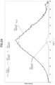
- FIG. 1 the results obtained by performing the peak separation of the P2p peak in the XPS spectrum of the carbon catalyst obtained in Example 1 are shown.
- “P1” represents the peak P 130.0
- “P2” represents the peak P 132.5
- “P3” represents the peak P 133.2
- “P4" represents the peak P 133.9
- “P5" represents the peak P 135.6 . Since the peak intensity of the "P3” was small, an enlarged diagram of the "P3” is also shown in FIG. 1 . In addition, the peak intensity of the "P5" was so small that the peak was not visually recognized in FIG. 1 .
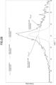
- FIG. 2A the results obtained by performing the peak separation in the XRD diffraction pattern of the carbon catalyst obtained in Example 1 are shown.
- FIG. 2B the results obtained by performing the peak separation in the XRD diffraction pattern of the carbon catalyst obtained in Comparative Example 1 are shown.
- FIG. 3 the results of the XPS measurement, the results of the XRD measurement, and the results of the oxygen reduction activity measurement in each of Examples 1 to 9 and Comparative Examples 1 and 2 are shown.
- the current density i 0.5 (mA/cm 2 ) of the carbon catalyst obtained in each of Examples 1 to 9 was significantly larger than that of the carbon catalyst obtained in each of Comparative Examples 1 and 2. That is, the oxygen reduction activity of the carbon catalyst obtained in each of Examples 1 to 9 was significantly higher than that of the carbon catalyst obtained in each of Comparative Examples 1 and 2.
- the performance retention ratio (%) of the carbon catalyst obtained in each of Examples 1 to 9 was significantly larger than that of the carbon catalyst obtained in each of Comparative Examples 1 and 2. That is, the carbon catalyst obtained in each of Examples 1 to 9 was also more excellent from the viewpoint of durability than the carbon catalyst obtained in each of Comparative Examples 1 and 2.
- the P 132.5 /C ratio of the carbon catalyst obtained in each of Examples 1 to 9 was significantly larger than that of the carbon catalyst obtained in each of Comparative Examples 1 and 2.
- the carbon catalyst obtained in each of Examples 1 to 9 exhibited excellent oxygen reduction activity and durability by containing a relatively large amount of the particular phosphorus atoms that exhibited the peak P 132.5 having a peak top within a range of 132.5 ⁇ 0.3 eV in the XPS measurement (that is, due to the relatively large P 2 /C ratio).
- the P 132.5 /P total ratio was 0.3025 or more, which was larger than that of the carbon catalyst obtained in each of Comparative Examples 1 and 2.
- the ratio of the peak f broad derived from a low-crystalline component was more than 72.83% (more specifically, 94.44% or more), and the ratio of the peak f narrow derived from ahigh-crystalline component was less than 27.17% (more specifically, 5.56% or less) in the XRD measurement.
- the current density i 0.5 and the performance retention ratio were particularly excellent compared to those of the carbon catalyst obtained in each of Examples 2, 3, 7, and 9.
- the P 132.5 /C ratio of the carbon catalyst obtained in each of Examples 1, 4, 5, 6, and 8 was more than 0.0038 (more specifically, 0.0057 or more), which was larger than that of the carbon catalyst obtained in each of Examples 2, 3, 7, and 9.
- the P/C ratio of the carbon catalyst obtained in each of Examples 1, 4, 5, 6, and 8 was more than 0.0080 (more specifically, 0.0100 or more), which was larger than that of the carbon catalyst obtained in Examples 2, 3, 7 and 9. Furthermore, the amount (atomic%) of the phosphorus atoms of the carbon catalyst obtained in each of Examples 1, 4, 5, 6, and 8 was more than 0.65 (more specifically, 0.79 or more), which was larger than that of the carbon catalyst obtained in each of Examples 2, 3, 7, and 9.
Landscapes
- Chemical & Material Sciences (AREA)
- Chemical Kinetics & Catalysis (AREA)
- Engineering & Computer Science (AREA)
- Materials Engineering (AREA)
- Electrochemistry (AREA)
- General Chemical & Material Sciences (AREA)
- Organic Chemistry (AREA)
- Composite Materials (AREA)
- Catalysts (AREA)
- Manufacturing & Machinery (AREA)
- Inert Electrodes (AREA)
Claims (4)
- Ein Kohlenstoffkatalysator, umfassend ein Metall und Phosphoratome, wobei das Metall eine oder mehrere Arten ist, ausgewählt aus einer Gruppe, bestehend aus Sc, Ti, V, Cr, Mn, Fe, Co, Ni, Cu und Zn,wobei der Kohlenstoffkatalysator ein Verhältnis einer Konzentration (Atom-%) der Phosphoratome bezogen auf die Konzentration (Atom-%) der Kohlenstoffatome bei einer Messung mittels Röntgen-Photoelektronenspektroskopie von 0,0005 oder mehr aufweist, wobei die Phosphoratome einen Peak mit einer Peak-Spitze in einem Bereich von 132,5 ± 0,3 eV und mit einer Halbwertsbreite von 2,0 ± 0,5 eV aufweisen, die durch Peak-Trennung eines Phosphoratom P2p-Peaks erhalten wird, undwobei der Kohlenstoffkatalysator eine Kohlenstoffstruktur aufweist, in der die Flächenverhältnisse (%) der folgenden zwei Peaks fbroad und fnarrow, erhalten durch Trennen eines Peaks in einer Nähe eines Beugungswinkels (2θ) von 26° in einem Röntgenbeugungsmuster bei einer Pulver-Röntgenbeugungsmessung, die folgende Bedingungen (a) und (b) erfüllen:(a) ein Peak fbroad mit einer Peakspitze in einem Bereich eines Beugungswinkels (2θ) von 23,5°± 3,5° und mit einer Halbwertsbreite von 10,0°± 5,0°: 73,0 % oder mehr und weniger als 100,0 %; und(b) ein Peak fnarrow mit einer Peakspitze in einem Bereich eines Beugungswinkels (2θ) von 26,5°± 1,0° und mit einer Halbwertsbreite von 3,5°± 3,0°: mehr als 0,0 % und 27,0 % oder weniger.
- Der Kohlenstoffkatalysator gemäß Anspruch 1,
wobei der Kohlenstoffkatalysator ein Verhältnis der Fläche des folgenden Peaks (2) bezogen auf die gesamte Fläche der folgenden fünf Peaks (1) bis (5) in der Messung mittels Röntgen-Photoelektronenspektroskopie von 0,3000 oder mehr aufweist, wobei die fünf Peaks durch die Peak-Trennung des Phosphoratom P2p-Peaks erhalten werden:(1) ein Peak mit einer Peakspitze in einem Bereich von 130,0 ± 0,3 eV und mit einer Halbwertsbreite von 2,0 ± 0,5 eV;(2) der Peak mit einer Peakspitze in einem Bereich von 132,5 ± 0,3 eV und mit einer Halbwertsbreite von 2,0 ± 0,5 eV;(3) ein Peak mit einer Peakspitze in einem Bereich von 133,2 ± 0,3 eV und mit einer Halbwertsbreite von 2,0 ± 0,5 eV;(4) ein Peak mit einer Peakspitze in einem Bereich von 133,9 ± 0,3 eV und mit einer Halbwertsbreite von 2,0 ± 0,5 eV; und(5) ein Peak mit einer Peakspitze in einem Bereich von 135,6 ± 0,4 eV und mit einer Halbwertsbreite von 2,0 ± 0,5 eV. - Eine Elektrode, umfassend den Kohlenstoffkatalysator nach Anspruch 1 oder 2.
- Eine Batterie, umfassend die Elektrode nach Anspruch 3.
Applications Claiming Priority (2)
| Application Number | Priority Date | Filing Date | Title |
|---|---|---|---|
| JP2016236828A JP6857878B2 (ja) | 2016-12-06 | 2016-12-06 | 炭素触媒並びにこれを含む電極及び電池 |
| PCT/JP2017/042951 WO2018105472A1 (ja) | 2016-12-06 | 2017-11-30 | 炭素触媒並びにこれを含む電極及び電池 |
Publications (3)
| Publication Number | Publication Date |
|---|---|
| EP3552698A1 EP3552698A1 (de) | 2019-10-16 |
| EP3552698A4 EP3552698A4 (de) | 2020-07-22 |
| EP3552698B1 true EP3552698B1 (de) | 2025-06-04 |
Family
ID=62491020
Family Applications (1)
| Application Number | Title | Priority Date | Filing Date |
|---|---|---|---|
| EP17878288.4A Active EP3552698B1 (de) | 2016-12-06 | 2017-11-30 | Kohlenstoffkatalysator und elektrode und batterie damit |
Country Status (7)
| Country | Link |
|---|---|
| US (1) | US11276865B2 (de) |
| EP (1) | EP3552698B1 (de) |
| JP (1) | JP6857878B2 (de) |
| KR (1) | KR102433923B1 (de) |
| CN (1) | CN110049814B (de) |
| CA (1) | CA3045977C (de) |
| WO (1) | WO2018105472A1 (de) |
Families Citing this family (2)
| Publication number | Priority date | Publication date | Assignee | Title |
|---|---|---|---|---|
| JP7175857B2 (ja) * | 2019-08-02 | 2022-11-21 | 日清紡ホールディングス株式会社 | 金属担持触媒、電池電極及び電池 |
| CN113363508B (zh) * | 2021-02-02 | 2022-10-28 | 井冈山大学 | 一种燃料电池用电催化剂及其制备方法 |
Family Cites Families (9)
| Publication number | Priority date | Publication date | Assignee | Title |
|---|---|---|---|---|
| JP3318767B2 (ja) * | 1991-03-02 | 2002-08-26 | ソニー株式会社 | 負極材料及びその製造方法並びにこれを用いた非水電解液電池 |
| US5294498A (en) | 1991-03-02 | 1994-03-15 | Sony Corporation | Anode material, method for producing it and non-aqueous electrolyte cell employing such anode materials |
| JPH1040913A (ja) * | 1996-07-24 | 1998-02-13 | Osaka Gas Co Ltd | リチウム二次電池負極用炭素材及びその製造方法並びにリチウム二次電池 |
| JP5149364B2 (ja) * | 2010-11-08 | 2013-02-20 | 国立大学法人群馬大学 | 炭素触媒及びその製造方法並びにこれを用いた電極及び電池 |
| CN103974900B (zh) * | 2011-12-12 | 2017-03-08 | 松下电器产业株式会社 | 碳系材料、电极催化剂、氧还原电极催化剂、气体扩散电极、水溶液电解装置和制备碳系材料的方法 |
| JP5743945B2 (ja) * | 2012-03-30 | 2015-07-01 | 株式会社東芝 | 酸素還元触媒と酸素還元触媒を用いた電気化学セル |
| JP5836866B2 (ja) * | 2012-03-30 | 2015-12-24 | 株式会社東芝 | 炭素電極とその製造方法およびそれを用いた光電変換素子 |
| KR101427343B1 (ko) | 2012-08-14 | 2014-08-07 | 한국과학기술원 | 질소 이외에 붕소, 인 중에서 선택된 어느 하나 이상의 추가적 도핑에 의해 산소 환원 반응성이 증가된 탄소 촉매의 제조방법 |
| WO2016088716A1 (ja) * | 2014-12-05 | 2016-06-09 | 日清紡ホールディングス株式会社 | 炭素触媒、電極及び電池 |
-
2016
- 2016-12-06 JP JP2016236828A patent/JP6857878B2/ja active Active
-
2017
- 2017-11-30 CA CA3045977A patent/CA3045977C/en active Active
- 2017-11-30 WO PCT/JP2017/042951 patent/WO2018105472A1/ja not_active Ceased
- 2017-11-30 US US16/464,996 patent/US11276865B2/en active Active
- 2017-11-30 EP EP17878288.4A patent/EP3552698B1/de active Active
- 2017-11-30 KR KR1020197017678A patent/KR102433923B1/ko active Active
- 2017-11-30 CN CN201780075751.1A patent/CN110049814B/zh active Active
Also Published As
| Publication number | Publication date |
|---|---|
| US20190296365A1 (en) | 2019-09-26 |
| JP6857878B2 (ja) | 2021-04-14 |
| CN110049814B (zh) | 2022-06-07 |
| KR102433923B1 (ko) | 2022-08-18 |
| CA3045977A1 (en) | 2018-06-14 |
| JP2018089591A (ja) | 2018-06-14 |
| CA3045977C (en) | 2025-05-27 |
| EP3552698A4 (de) | 2020-07-22 |
| EP3552698A1 (de) | 2019-10-16 |
| CN110049814A (zh) | 2019-07-23 |
| KR20190087507A (ko) | 2019-07-24 |
| US11276865B2 (en) | 2022-03-15 |
| WO2018105472A1 (ja) | 2018-06-14 |
Similar Documents
| Publication | Publication Date | Title |
|---|---|---|
| Hu et al. | High‐performance, long‐life, rechargeable Li–CO2 batteries based on a 3D holey graphene cathode implanted with single iron atoms | |
| Wang et al. | Nanoparticle cookies derived from metal‐organic frameworks: controlled synthesis and application in anode materials for lithium‐ion batteries | |
| Yang et al. | [001] preferentially-oriented 2D tungsten disulfide nanosheets as anode materials for superior lithium storage | |
| Zhang et al. | Sulfur-doping achieves efficient oxygen reduction in pyrolyzed zeolitic imidazolate frameworks | |
| EP2371449B1 (de) | Kohlenstoffkatalysator, herstellungsverfahren für den kohlenstoffkatalysator sowie elektrode und batterie mit dem kohlenstoffkatalysator | |
| Chakrabarty et al. | Urea oxidation electrocatalysis on nickel hydroxide: the role of disorder | |
| Noori et al. | Carbon supported Cu-Sn bimetallic alloy as an excellent low-cost cathode catalyst for enhancing oxygen reduction reaction in microbial fuel cell | |
| Guan et al. | Activation of lattice oxygen in nitrogen-doped high-entropy oxide nanosheets for highly efficient oxygen evolution reaction | |
| Yang et al. | Phosphorus vacancies and heterojunction interface as effective lithium‐peroxide promoter for long‐cycle life lithium–oxygen batteries | |
| EP3466532B1 (de) | Kohlenstoffkatalysator, elektrode und batterie | |
| Lu et al. | Co-Mn hybrid oxides supported on N-doped graphene as efficient electrocatalysts for reversible oxygen electrodes | |
| EP3552698B1 (de) | Kohlenstoffkatalysator und elektrode und batterie damit | |
| Hu et al. | Mixed Fe-Mo carbide prepared by a sonochemical synthesis as highly efficient nitrate reduction electrocatalyst | |
| Kavinkumar et al. | Coupling of precisely engineered Co3O4@ FeCo2S4 with a Mo2TiC2Tx MXene architecture to produce a durable bifunctional electrocatalyst for efficient water electrolysis | |
| Zhang et al. | Synergizing single-atom and carbon-encapsulated nanoparticles of Fe for efficient oxygen reduction and durable Zn–air batteries | |
| Dambournet et al. | Dual lithium insertion and conversion mechanisms in a titanium-based mixed-anion nanocomposite | |
| Lopez et al. | A functionalized Co2P negative electrode for batteries demanding high Li-potential reaction | |
| Kuang et al. | Manganese molybdate cathodes with dual-redox centers for aqueous zinc-ion batteries: impact of electrolyte on electrochemistry | |
| Giacco et al. | Enhancement of the performance in Li-O2 cells of a NiCo2O4 based porous positive electrode by Cr (III) doping | |
| Li et al. | Pre‐activation and Defects Introduced via Citric Acid to Mitigate Capacity and Voltage Fading in Li‐rich Cathode | |
| Nivedha et al. | ZnMn2O4/Carbon composite recycled from spent Zinc-Carbon batteries for Zn-Air battery applications | |
| Kim et al. | Synthesis, Structure, and Electrochemical Characteristics of Overlithiated Li1+ x (Ni z Co1− 2 z Mn z) 1− x O2 (z= 0.1–0.4 and x= 0.0–0.1) Positive Electrodes Prepared by Spray-Drying Method | |
| Yang et al. | The effect of organic ligand skeletons of 2D π–d conjugated metal–organic frameworks on their OER performance and stability | |
| Wang | Electrochemical studies of the applications of novel carbon-based materials | |
| He | Development of Self-Supported Electrodes for Alkaline Electrochemical Water Splitting |
Legal Events
| Date | Code | Title | Description |
|---|---|---|---|
| STAA | Information on the status of an ep patent application or granted ep patent |
Free format text: STATUS: THE INTERNATIONAL PUBLICATION HAS BEEN MADE |
|
| PUAI | Public reference made under article 153(3) epc to a published international application that has entered the european phase |
Free format text: ORIGINAL CODE: 0009012 |
|
| STAA | Information on the status of an ep patent application or granted ep patent |
Free format text: STATUS: REQUEST FOR EXAMINATION WAS MADE |
|
| 17P | Request for examination filed |
Effective date: 20190702 |
|
| AK | Designated contracting states |
Kind code of ref document: A1 Designated state(s): AL AT BE BG CH CY CZ DE DK EE ES FI FR GB GR HR HU IE IS IT LI LT LU LV MC MK MT NL NO PL PT RO RS SE SI SK SM TR |
|
| AX | Request for extension of the european patent |
Extension state: BA ME |
|
| DAV | Request for validation of the european patent (deleted) | ||
| DAX | Request for extension of the european patent (deleted) | ||
| A4 | Supplementary search report drawn up and despatched |
Effective date: 20200623 |
|
| RIC1 | Information provided on ipc code assigned before grant |
Ipc: B01J 21/18 20060101ALI20200617BHEP Ipc: C08K 3/04 20060101ALI20200617BHEP Ipc: B01J 27/185 20060101AFI20200617BHEP Ipc: H01M 4/13 20100101ALI20200617BHEP Ipc: H01M 4/62 20060101ALI20200617BHEP Ipc: H01M 4/90 20060101ALI20200617BHEP |
|
| STAA | Information on the status of an ep patent application or granted ep patent |
Free format text: STATUS: EXAMINATION IS IN PROGRESS |
|
| 17Q | First examination report despatched |
Effective date: 20220301 |
|
| GRAP | Despatch of communication of intention to grant a patent |
Free format text: ORIGINAL CODE: EPIDOSNIGR1 |
|
| STAA | Information on the status of an ep patent application or granted ep patent |
Free format text: STATUS: GRANT OF PATENT IS INTENDED |
|
| INTG | Intention to grant announced |
Effective date: 20250221 |
|
| GRAS | Grant fee paid |
Free format text: ORIGINAL CODE: EPIDOSNIGR3 |
|
| GRAA | (expected) grant |
Free format text: ORIGINAL CODE: 0009210 |
|
| STAA | Information on the status of an ep patent application or granted ep patent |
Free format text: STATUS: THE PATENT HAS BEEN GRANTED |
|
| AK | Designated contracting states |
Kind code of ref document: B1 Designated state(s): AL AT BE BG CH CY CZ DE DK EE ES FI FR GB GR HR HU IE IS IT LI LT LU LV MC MK MT NL NO PL PT RO RS SE SI SK SM TR |
|
| REG | Reference to a national code |
Ref country code: GB Ref legal event code: FG4D |
|
| REG | Reference to a national code |
Ref country code: CH Ref legal event code: EP |
|
| REG | Reference to a national code |
Ref country code: DE Ref legal event code: R096 Ref document number: 602017089823 Country of ref document: DE |
|
| REG | Reference to a national code |
Ref country code: IE Ref legal event code: FG4D |
|
| REG | Reference to a national code |
Ref country code: NL Ref legal event code: MP Effective date: 20250604 |
|
| PG25 | Lapsed in a contracting state [announced via postgrant information from national office to epo] |
Ref country code: ES Free format text: LAPSE BECAUSE OF FAILURE TO SUBMIT A TRANSLATION OF THE DESCRIPTION OR TO PAY THE FEE WITHIN THE PRESCRIBED TIME-LIMIT Effective date: 20250604 Ref country code: FI Free format text: LAPSE BECAUSE OF FAILURE TO SUBMIT A TRANSLATION OF THE DESCRIPTION OR TO PAY THE FEE WITHIN THE PRESCRIBED TIME-LIMIT Effective date: 20250604 |
|
| REG | Reference to a national code |
Ref country code: LT Ref legal event code: MG9D |
|
| PG25 | Lapsed in a contracting state [announced via postgrant information from national office to epo] |
Ref country code: GR Free format text: LAPSE BECAUSE OF FAILURE TO SUBMIT A TRANSLATION OF THE DESCRIPTION OR TO PAY THE FEE WITHIN THE PRESCRIBED TIME-LIMIT Effective date: 20250905 Ref country code: NO Free format text: LAPSE BECAUSE OF FAILURE TO SUBMIT A TRANSLATION OF THE DESCRIPTION OR TO PAY THE FEE WITHIN THE PRESCRIBED TIME-LIMIT Effective date: 20250904 |
|
| PG25 | Lapsed in a contracting state [announced via postgrant information from national office to epo] |
Ref country code: PL Free format text: LAPSE BECAUSE OF FAILURE TO SUBMIT A TRANSLATION OF THE DESCRIPTION OR TO PAY THE FEE WITHIN THE PRESCRIBED TIME-LIMIT Effective date: 20250604 |
|
| PG25 | Lapsed in a contracting state [announced via postgrant information from national office to epo] |
Ref country code: BG Free format text: LAPSE BECAUSE OF FAILURE TO SUBMIT A TRANSLATION OF THE DESCRIPTION OR TO PAY THE FEE WITHIN THE PRESCRIBED TIME-LIMIT Effective date: 20250604 |
|
| PG25 | Lapsed in a contracting state [announced via postgrant information from national office to epo] |
Ref country code: HR Free format text: LAPSE BECAUSE OF FAILURE TO SUBMIT A TRANSLATION OF THE DESCRIPTION OR TO PAY THE FEE WITHIN THE PRESCRIBED TIME-LIMIT Effective date: 20250604 |
|
| PG25 | Lapsed in a contracting state [announced via postgrant information from national office to epo] |
Ref country code: RS Free format text: LAPSE BECAUSE OF FAILURE TO SUBMIT A TRANSLATION OF THE DESCRIPTION OR TO PAY THE FEE WITHIN THE PRESCRIBED TIME-LIMIT Effective date: 20250904 |
|
| PG25 | Lapsed in a contracting state [announced via postgrant information from national office to epo] |
Ref country code: LV Free format text: LAPSE BECAUSE OF FAILURE TO SUBMIT A TRANSLATION OF THE DESCRIPTION OR TO PAY THE FEE WITHIN THE PRESCRIBED TIME-LIMIT Effective date: 20250604 |
|
| PG25 | Lapsed in a contracting state [announced via postgrant information from national office to epo] |
Ref country code: NL Free format text: LAPSE BECAUSE OF FAILURE TO SUBMIT A TRANSLATION OF THE DESCRIPTION OR TO PAY THE FEE WITHIN THE PRESCRIBED TIME-LIMIT Effective date: 20250604 |
|
| PG25 | Lapsed in a contracting state [announced via postgrant information from national office to epo] |
Ref country code: PT Free format text: LAPSE BECAUSE OF FAILURE TO SUBMIT A TRANSLATION OF THE DESCRIPTION OR TO PAY THE FEE WITHIN THE PRESCRIBED TIME-LIMIT Effective date: 20251006 |
|
| REG | Reference to a national code |
Ref country code: AT Ref legal event code: MK05 Ref document number: 1799865 Country of ref document: AT Kind code of ref document: T Effective date: 20250604 |
|
| PG25 | Lapsed in a contracting state [announced via postgrant information from national office to epo] |
Ref country code: IS Free format text: LAPSE BECAUSE OF FAILURE TO SUBMIT A TRANSLATION OF THE DESCRIPTION OR TO PAY THE FEE WITHIN THE PRESCRIBED TIME-LIMIT Effective date: 20251004 |
|
| PGFP | Annual fee paid to national office [announced via postgrant information from national office to epo] |
Ref country code: DE Payment date: 20251128 Year of fee payment: 9 |
|
| PGFP | Annual fee paid to national office [announced via postgrant information from national office to epo] |
Ref country code: GB Payment date: 20251127 Year of fee payment: 9 |
|
| PG25 | Lapsed in a contracting state [announced via postgrant information from national office to epo] |
Ref country code: SM Free format text: LAPSE BECAUSE OF FAILURE TO SUBMIT A TRANSLATION OF THE DESCRIPTION OR TO PAY THE FEE WITHIN THE PRESCRIBED TIME-LIMIT Effective date: 20250604 Ref country code: AT Free format text: LAPSE BECAUSE OF FAILURE TO SUBMIT A TRANSLATION OF THE DESCRIPTION OR TO PAY THE FEE WITHIN THE PRESCRIBED TIME-LIMIT Effective date: 20250604 |
|
| PGFP | Annual fee paid to national office [announced via postgrant information from national office to epo] |
Ref country code: FR Payment date: 20251124 Year of fee payment: 9 |
|
| PG25 | Lapsed in a contracting state [announced via postgrant information from national office to epo] |
Ref country code: CZ Free format text: LAPSE BECAUSE OF FAILURE TO SUBMIT A TRANSLATION OF THE DESCRIPTION OR TO PAY THE FEE WITHIN THE PRESCRIBED TIME-LIMIT Effective date: 20250604 |
|
| PG25 | Lapsed in a contracting state [announced via postgrant information from national office to epo] |
Ref country code: EE Free format text: LAPSE BECAUSE OF FAILURE TO SUBMIT A TRANSLATION OF THE DESCRIPTION OR TO PAY THE FEE WITHIN THE PRESCRIBED TIME-LIMIT Effective date: 20250604 |
|
| PG25 | Lapsed in a contracting state [announced via postgrant information from national office to epo] |
Ref country code: RO Free format text: LAPSE BECAUSE OF FAILURE TO SUBMIT A TRANSLATION OF THE DESCRIPTION OR TO PAY THE FEE WITHIN THE PRESCRIBED TIME-LIMIT Effective date: 20250604 Ref country code: SK Free format text: LAPSE BECAUSE OF FAILURE TO SUBMIT A TRANSLATION OF THE DESCRIPTION OR TO PAY THE FEE WITHIN THE PRESCRIBED TIME-LIMIT Effective date: 20250604 |
|
| PG25 | Lapsed in a contracting state [announced via postgrant information from national office to epo] |
Ref country code: IT Free format text: LAPSE BECAUSE OF FAILURE TO SUBMIT A TRANSLATION OF THE DESCRIPTION OR TO PAY THE FEE WITHIN THE PRESCRIBED TIME-LIMIT Effective date: 20250604 |
|
| REG | Reference to a national code |
Ref country code: DE Ref legal event code: R097 Ref document number: 602017089823 Country of ref document: DE |
|
| PLBE | No opposition filed within time limit |
Free format text: ORIGINAL CODE: 0009261 |
|
| STAA | Information on the status of an ep patent application or granted ep patent |
Free format text: STATUS: NO OPPOSITION FILED WITHIN TIME LIMIT |
|
| PG25 | Lapsed in a contracting state [announced via postgrant information from national office to epo] |
Ref country code: DK Free format text: LAPSE BECAUSE OF FAILURE TO SUBMIT A TRANSLATION OF THE DESCRIPTION OR TO PAY THE FEE WITHIN THE PRESCRIBED TIME-LIMIT Effective date: 20250604 |
|
| REG | Reference to a national code |
Ref country code: CH Ref legal event code: L10 Free format text: ST27 STATUS EVENT CODE: U-0-0-L10-L00 (AS PROVIDED BY THE NATIONAL OFFICE) Effective date: 20260416 |