EP3552566B1 - Mechanische verriegelung für chirurgisches ultraschallinstrument - Google Patents
Mechanische verriegelung für chirurgisches ultraschallinstrument Download PDFInfo
- Publication number
- EP3552566B1 EP3552566B1 EP19168796.1A EP19168796A EP3552566B1 EP 3552566 B1 EP3552566 B1 EP 3552566B1 EP 19168796 A EP19168796 A EP 19168796A EP 3552566 B1 EP3552566 B1 EP 3552566B1
- Authority
- EP
- European Patent Office
- Prior art keywords
- assembly
- shaft assembly
- handle assembly
- instrument
- ultrasonic
- Prior art date
- Legal status (The legal status is an assumption and is not a legal conclusion. Google has not performed a legal analysis and makes no representation as to the accuracy of the status listed.)
- Active
Links
Images


Classifications
-
- A—HUMAN NECESSITIES
- A61—MEDICAL OR VETERINARY SCIENCE; HYGIENE
- A61B—DIAGNOSIS; SURGERY; IDENTIFICATION
- A61B17/00—Surgical instruments, devices or methods
- A61B17/32—Surgical cutting instruments
- A61B17/320068—Surgical cutting instruments using mechanical vibrations, e.g. ultrasonic
- A61B17/320092—Surgical cutting instruments using mechanical vibrations, e.g. ultrasonic with additional movable means for clamping or cutting tissue, e.g. with a pivoting jaw
-
- A—HUMAN NECESSITIES
- A61—MEDICAL OR VETERINARY SCIENCE; HYGIENE
- A61B—DIAGNOSIS; SURGERY; IDENTIFICATION
- A61B17/00—Surgical instruments, devices or methods
- A61B17/28—Surgical forceps
- A61B17/29—Forceps for use in minimally invasive surgery
-
- A—HUMAN NECESSITIES
- A61—MEDICAL OR VETERINARY SCIENCE; HYGIENE
- A61B—DIAGNOSIS; SURGERY; IDENTIFICATION
- A61B17/00—Surgical instruments, devices or methods
- A61B17/32—Surgical cutting instruments
- A61B17/320068—Surgical cutting instruments using mechanical vibrations, e.g. ultrasonic
-
- A—HUMAN NECESSITIES
- A61—MEDICAL OR VETERINARY SCIENCE; HYGIENE
- A61B—DIAGNOSIS; SURGERY; IDENTIFICATION
- A61B18/00—Surgical instruments, devices or methods for transferring non-mechanical forms of energy to or from the body
- A61B18/04—Surgical instruments, devices or methods for transferring non-mechanical forms of energy to or from the body by heating
- A61B18/12—Surgical instruments, devices or methods for transferring non-mechanical forms of energy to or from the body by heating by passing a current through the tissue to be heated, e.g. high-frequency current
- A61B18/14—Probes or electrodes therefor
- A61B18/1442—Probes having pivoting end effectors, e.g. forceps
- A61B18/1445—Probes having pivoting end effectors, e.g. forceps at the distal end of a shaft, e.g. forceps or scissors at the end of a rigid rod
-
- A—HUMAN NECESSITIES
- A61—MEDICAL OR VETERINARY SCIENCE; HYGIENE
- A61B—DIAGNOSIS; SURGERY; IDENTIFICATION
- A61B17/00—Surgical instruments, devices or methods
- A61B2017/00367—Details of actuation of instruments, e.g. relations between pushing buttons, or the like, and activation of the tool, working tip, or the like
- A61B2017/00398—Details of actuation of instruments, e.g. relations between pushing buttons, or the like, and activation of the tool, working tip, or the like using powered actuators, e.g. stepper motors, solenoids
- A61B2017/00402—Piezo electric actuators
-
- A—HUMAN NECESSITIES
- A61—MEDICAL OR VETERINARY SCIENCE; HYGIENE
- A61B—DIAGNOSIS; SURGERY; IDENTIFICATION
- A61B17/00—Surgical instruments, devices or methods
- A61B2017/0046—Surgical instruments, devices or methods with a releasable handle; with handle and operating part separable
-
- A—HUMAN NECESSITIES
- A61—MEDICAL OR VETERINARY SCIENCE; HYGIENE
- A61B—DIAGNOSIS; SURGERY; IDENTIFICATION
- A61B17/00—Surgical instruments, devices or methods
- A61B2017/0046—Surgical instruments, devices or methods with a releasable handle; with handle and operating part separable
- A61B2017/00473—Distal part, e.g. tip or head
-
- A—HUMAN NECESSITIES
- A61—MEDICAL OR VETERINARY SCIENCE; HYGIENE
- A61B—DIAGNOSIS; SURGERY; IDENTIFICATION
- A61B17/00—Surgical instruments, devices or methods
- A61B2017/00477—Coupling
-
- A—HUMAN NECESSITIES
- A61—MEDICAL OR VETERINARY SCIENCE; HYGIENE
- A61B—DIAGNOSIS; SURGERY; IDENTIFICATION
- A61B17/00—Surgical instruments, devices or methods
- A61B17/32—Surgical cutting instruments
- A61B17/320068—Surgical cutting instruments using mechanical vibrations, e.g. ultrasonic
- A61B2017/320072—Working tips with special features, e.g. extending parts
- A61B2017/320074—Working tips with special features, e.g. extending parts blade
-
- A—HUMAN NECESSITIES
- A61—MEDICAL OR VETERINARY SCIENCE; HYGIENE
- A61B—DIAGNOSIS; SURGERY; IDENTIFICATION
- A61B17/00—Surgical instruments, devices or methods
- A61B17/32—Surgical cutting instruments
- A61B17/320068—Surgical cutting instruments using mechanical vibrations, e.g. ultrasonic
- A61B17/320092—Surgical cutting instruments using mechanical vibrations, e.g. ultrasonic with additional movable means for clamping or cutting tissue, e.g. with a pivoting jaw
- A61B2017/320094—Surgical cutting instruments using mechanical vibrations, e.g. ultrasonic with additional movable means for clamping or cutting tissue, e.g. with a pivoting jaw additional movable means performing clamping operation
-
- A—HUMAN NECESSITIES
- A61—MEDICAL OR VETERINARY SCIENCE; HYGIENE
- A61B—DIAGNOSIS; SURGERY; IDENTIFICATION
- A61B17/00—Surgical instruments, devices or methods
- A61B17/32—Surgical cutting instruments
- A61B17/320068—Surgical cutting instruments using mechanical vibrations, e.g. ultrasonic
- A61B17/320092—Surgical cutting instruments using mechanical vibrations, e.g. ultrasonic with additional movable means for clamping or cutting tissue, e.g. with a pivoting jaw
- A61B2017/320095—Surgical cutting instruments using mechanical vibrations, e.g. ultrasonic with additional movable means for clamping or cutting tissue, e.g. with a pivoting jaw with sealing or cauterizing means
-
- A—HUMAN NECESSITIES
- A61—MEDICAL OR VETERINARY SCIENCE; HYGIENE
- A61B—DIAGNOSIS; SURGERY; IDENTIFICATION
- A61B18/00—Surgical instruments, devices or methods for transferring non-mechanical forms of energy to or from the body
- A61B2018/00994—Surgical instruments, devices or methods for transferring non-mechanical forms of energy to or from the body combining two or more different kinds of non-mechanical energy or combining one or more non-mechanical energies with ultrasound
-
- A—HUMAN NECESSITIES
- A61—MEDICAL OR VETERINARY SCIENCE; HYGIENE
- A61B—DIAGNOSIS; SURGERY; IDENTIFICATION
- A61B90/00—Instruments, implements or accessories specially adapted for surgery or diagnosis and not covered by any of the groups A61B1/00 - A61B50/00, e.g. for luxation treatment or for protecting wound edges
- A61B90/08—Accessories or related features not otherwise provided for
- A61B2090/0807—Indication means
- A61B2090/0808—Indication means for indicating correct assembly of components, e.g. of the surgical apparatus
Definitions
- a variety of surgical instruments include an end effector having a blade element that vibrates at ultrasonic frequencies to cut and/or seal tissue (e.g., by denaturing proteins in tissue cells). These instruments include piezoelectric elements that convert electrical power into ultrasonic vibrations, which are communicated along an acoustic waveguide to the blade element. The precision of cutting and coagulation may be controlled by the surgeon's technique and adjusting the power level, blade edge, tissue traction and blade pressure.
- ultrasonic surgical instruments include the HARMONIC ACE ® Ultrasonic Shears, the HARMONIC WAVE ® Ultrasonic Shears, the HARMONIC FOCUS ® Ultrasonic Shears, and the HARMONIC SYNERGY ® Ultrasonic Blades, all by Ethicon Endo-Surgery, Inc. of Cincinnati, Ohio.
- ultrasonic surgical instruments may include a cordless transducer such as that disclosed in U.S. Pub. No. 2012/0112687, entitled “Recharge System for Medical Devices,” published May 10, 2012 ; U.S. Pub. No. 2012/0116265, entitled “Surgical Instrument with Charging Devices,” published May 10, 2012 .
- ultrasonic surgical instruments may include an articulating shaft section. Examples of such ultrasonic surgical instruments are disclosed in U.S. Pub. No. 2014/0005701, entitled “Surgical Instruments with Articulating Shafts,” published January 2, 2014 ; and U.S. Pub. No. 2014/0114334, entitled “Flexible Harmonic Waveguides/Blades for Surgical Instruments,” published April 24, 2014 .
- an ultrasonic surgical instrument having a handle assembly, a waveguide extending distally from the handle assembly, an end-effector located at a distal end of the waveguide, and a clamp assembly removably mounted to the handle assembly, the clamp assembly including a clamp arm pivotally mounted on the distal end of the clamp assembly for pivotal movement with respect to the end effector.
- the invention relates to an ultrasonic instrument as defined in claim 1. Further embodiments are specified in the dependent claims.
- proximal and distal are defined herein relative to a human or robotic operator of the surgical instrument.
- proximal refers the position of an element closer to the human or robotic operator of the surgical instrument and further away from the surgical end effector of the surgical instrument.
- distal refers to the position of an element closer to the surgical end effector of the surgical instrument and further away from the human or robotic operator of the surgical instrument.
- upper,” “lower,” “lateral,” “transverse,” “bottom,” “top,” are relative terms to provide additional clarity to the figure descriptions provided below. The terms “upper,” “lower,” “lateral,” “transverse,” “bottom,” “top,” are thus not intended to unnecessarily limit the invention described herein.
- first and second are used herein to distinguish one or more portions of the surgical instrument.
- a first assembly and a second assembly may be alternatively and respectively described as a second assembly and a first assembly.
- first and second and other numerical designations are merely exemplary of such terminology and are not intended to unnecessarily limit the invention described herein.
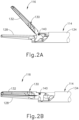
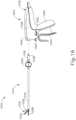
- FIGS. 1-2B show a first exemplary ultrasonic surgical instrument (110) that includes a first modular assembly shown as a handle assembly (112), a second modular assembly shown as a shaft assembly (114) extending distally from handle assembly (112), and an end effector (116) arranged at a distal end of shaft assembly (114).
- Handle assembly (112) comprises a body (118) including a pistol grip (120) and energy control buttons (122) configured to be manipulated by a surgeon to control various aspects of tissue treatment energy delivered by surgical instrument (110).
- a trigger (124) is coupled to a lower portion of body (118) and is pivotable toward and away from pistol grip (120) to selectively actuate end effector (116).
- handle assembly (112) may comprise a scissor grip configuration, for example.
- Body (118) houses an ultrasonic transducer (126), shown schematically in FIG. 1 , configured to deliver ultrasonic energy to end effector (116), as described in greater detail below.
- Body (118) may also be referred to herein as a housing (118) and may include one component or an assembly of components.
- the terms “body” and “housing” are thus not intended to unnecessarily limit the invention described herein to any number of discrete components.
- end effector (116) includes an ultrasonic blade (128) and a clamp arm (130) configured to selectively pivot toward and away from ultrasonic blade (128) for clamping tissue therebetween.
- Clamp arm (130) includes a clamp pad (132) arranged on a clamping side thereof and is moveable from an open position shown in FIG. 2A to a closed position shown in FIG. 2B .
- ultrasonic blade (128) is acoustically coupled with ultrasonic transducer (126), which is configured to drive (i.e., vibrate) ultrasonic blade (128) at ultrasonic frequencies for cutting and/or sealing tissue positioned in contact with ultrasonic blade (128).
- Clamp arm (130) is operatively coupled with trigger (124) such that clamp arm (130) is configured to pivot toward ultrasonic blade (128), to the closed position, in response to pivoting of trigger (124) toward pistol grip (120). Further, clamp arm (130) is configured to pivot away from ultrasonic blade (128), to the open position in response to pivoting of trigger (124) away from pistol grip (120).
- trigger (124) Various suitable ways in which clamp arm (130) may be coupled with trigger (124) will be apparent to those of ordinary skill in the art in view of the teachings provided herein.
- one or more resilient members may be incorporated to bias clamp arm (130) and/or trigger (124) toward the open position.
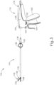
- Shaft assembly (114) of the present example extends along a longitudinal axis and includes an outer tube (134), an inner tube (136) received within outer tube (134), and an ultrasonic waveguide (138) supported within and extending longitudinally through inner tube (136).
- Ultrasonic blade (128) is formed integrally with and extends distally from waveguide (138).
- a proximal end of clamp arm (130) is pivotally coupled to distal ends of outer and inner tubes (134, 136), enabling clamp arm (130) to pivot relative to shaft assembly (114) about a pivot axis defined by a pivot pin (140) (see FIGS. 2A- 2B ) extending transversely through the distal end of inner tube (136).
- inner tube (136) is longitudinally fixed relative to handle assembly (118), and outer tube (134) is configured to translate relative to inner tube (136) and handle assembly (118), along the longitudinal axis of shaft assembly (114).
- clamp arm (130) pivots about its pivot axis toward its open position.
- clamp arm (130) pivots about its pivot axis in an opposite direction toward its closed position.
- a proximal end of outer tube (134) is operatively coupled with trigger (124) such that actuation of trigger (124) causes translation of outer tube (134) relative to inner tube (136), thereby opening or closing clamp arm (130) as discussed above.
- outer tube (134) may be longitudinally fixed and inner tube (136) may be configured to translate for moving clamp arm (130) between the open and closed positions.
- inner tube (136) may be configured to translate for moving clamp arm (130) between the open and closed positions.
- Shaft assembly (114) and end effector (116) are configured to rotate together relative to body (118) about the longitudinal axis defined by shaft assembly (114).
- shaft assembly (114) further includes a rotation knob (142) arranged at a proximal end thereof as well as a shaft coupler (143) configured to mechanically connect to body coupler (144) of handle assembly (112).
- Rotation knob (142) is rotatably coupled to body (118) of handle assembly (112) and is rotationally fixed to outer tube (134), inner tube (136), and waveguide (138) by a coupling pin (not shown) extending transversely therethrough.
- Coupling pin (not shown) is arranged at a longitudinal location corresponding to an acoustic node of waveguide (138).
- rotation knob (142) may be rotationally fixed to the remaining components of shaft assembly (114) in various other manners.
- Rotation knob (142) is configured to be gripped by an operator to selectively manipulate the rotational orientation of shaft assembly (114) and end effector (116) relative to handle assembly (112).
- acoustic and mechanical connections between shaft assembly (114) and handle assembly (112) are described in greater detail in U.S. Pat. Pub. No. US20190008546A1, entitled “Acoustic Drivetrain with External Collar at Nodal Position," filed on July 10, 2017 and U.S. Pat. Pub. No. US20190008547A1, entitled “Features to Couple Acoustic Drivetrain Components in Ultrasonic Surgical Instrument,” filed on July 10, 2017 .
- FIGS. 1-3 show additional details of ultrasonic transducer (126) and waveguide (138).
- ultrasonic transducer (126) and waveguide (138) are configured to threadedly couple together.
- waveguide (138) is configured to acoustically couple ultrasonic transducer (126) with ultrasonic blade (128), and thereby communicate ultrasonic mechanical vibrations from ultrasonic transducer (126) to blade (128).
- ultrasonic transducer (126), waveguide (138), and ultrasonic blade (128) together define an acoustic assembly of ultrasonic surgical instrument (110).
- Ultrasonic transducer (126) is rotatably supported within body (118) of handle assembly (112) and is configured to rotate with shaft assembly (114), including waveguide (138), and end effector (116) about the longitudinal axis of shaft assembly (114).
- Ultrasonic transducer (126) is electrically coupled with a generator (not shown), which may be provided externally of ultrasonic surgical instrument (110) or integrated within surgical instrument (110). During use, generator (not shown) powers ultrasonic ultrasonic transducer (126) to produce ultrasonic mechanical vibrations, which are communicated distally through waveguide (138) to ultrasonic blade (128). Ultrasonic blade (128) is caused to oscillate longitudinally in the range of approximately 10 to 500 microns peak-to-peak, for example, and in some instances in the range of approximately 20 to 200 microns, at a predetermined vibratory frequency f o of approximately 50 kHz, for example.
- Vibrating ultrasonic blade (128) may be positioned in direct contact with tissue, with or without assistive clamping force provided by clamp arm (130), to impart ultrasonic vibrational energy to the tissue and thereby cut and/or seal the tissue.
- blade (128) may cut through tissue clamped between clamp arm (130) and a clamping side of blade (128), or blade (128) may cut through tissue positioned in contact with an oppositely disposed non-clamping side of blade (128) having an edge, for example during a "back-cutting" movement.
- waveguide (138) may be configured to amplify the ultrasonic vibrations delivered to blade (128).
- Waveguide (138) may include various features operable to control the gain of the vibrations, and/or features suitable to tune waveguide (138) to a selected resonant frequency.
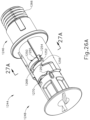
- ultrasonic transducer (26) includes a first resonator (or “end-bell”) (145), a conically shaped second resonator (or “fore-bell”) (146), and a transduction portion arranged between end-bell (145) and fore-bell (146) that includes a plurality of piezoelectric elements (148).
- a compression bolt (not shown) extends distally, coaxially through end-bell (145) and piezoelectric elements (148) and is threadedly received within a proximal end of fore-bell (146).
- a velocity transformer (or “horn”) (150) extends distally from fore-bell (146) and includes an internally threaded bore (152) configured to receive and threadedly couple with an externally threaded proximal tip (154) of waveguide (38) as shown in FIGS. 4-5 .
- first modular assembly (12) in the present example is reusable whereas second modular assembly (114) may be disconnected and replaced with an unused, replacement second modular assembly (114).
- first modular assembly (112) is separable from second modular assembly (114)
- mechanical lockout assemblies (544, 544', 644, 744, 844, 944, 1044, 1144, 1244) are shown in distinct positions between reusable and replaceable features for removable connection, any of the following mechanical lockout assemblies (544, 544', 644, 744, 844, 944, 1044, 1144, 1244), it will be appreciated that mechanical lockout assemblies (544, 544', 644, 744, 844, 944, 1044, 1144, 1244) may be incorporated into any surgical instrument described herein, exchanged, or moved so as to make one or more portions of a surgical instrument removable from a remainder of the surgical instrument. Two general forms of mechanical lockout varieties are shown and described below.
- mechanical lockout assembly that that effectively locks the clamp arm, thereby preventing the operator from clamping on tissue with the end effector.
- a mechanical lockout assembly that effectively locks the energy control buttons, thereby preventing the operator from activating the ultrasonic blade.
- mechanical lockout assemblies (544, 544', 644, 744, 844, 944, 1044, 1144, 1244) are intended to cover both mechanical lockout assembly that effectively locks the energy control buttons, thereby preventing the operator from activating the ultrasonic blade.
- mechanical lockout assemblies (544, 544', 644, 744, 844, 944, 1044, 1144, 1244) are intended to cover both energy control button lockouts preventing activation of ultrasonic blade and trigger lockouts preventing closure of clamp arm assembly toward ultrasonic blade. It is also appreciated that one or more of these mechanical lockout assemblies (544, 544', 644, 744, 844, 944, 1044, 1144, 1244) may be used in combination with another mechanical lockout assemblies (544, 544', 644, 744, 844, 944, 1044, 1144, 1244).
- FIGS. 6-7B show a second exemplary ultrasonic surgical instrument (510) including a first mechanical lockout assembly (544).
- FIG. 6 shows ultrasonic surgical instrument (510) as comprising a first modular assembly shown as a handle assembly (512), a second modular assembly shown as a shaft assembly (514), an end effector (516), a body (518), a pistol grip (520), energy control buttons (522), a trigger (524), an ultrasonic transducer (526), an ultrasonic blade (528), a clamp arm (530), a clamp pad (532), an outer tube (534), an inner tube (536), an ultrasonic waveguide (538), and a rotation knob (542).
- FIGS. 7A-7B show instrument (510) as including a mechanical lockout assembly (544).
- Mechanical lockout assembly (544) includes a barrier (546) that translates between a locked configuration and an unlocked configuration.
- Barrier (546) includes at least one body portion, with two body portions (548, 550) being shown in FIGS. 7A-7B .
- Body portion (550) includes at least one aperture (552) disposed within body portion (550), with two apertures (552) being shown in FIGS. 7A-7B .
- Barrier (546) is shown as a resilient elongated member that is disposed within handle assembly (512), however, barrier (546) may be operatively coupled to shaft assembly (514) and may be a variety of shapes and forms.
- Handle assembly (512) includes energy control buttons (522) separated by a passageway (554) from switches (556). As shown in FIG. 7A , it is appreciated that aperture (550) may not extend completely through body portion (550) to enable energy control buttons (522) to mechanically actuate switches (556). As previously described with connection to the previous embodiment, while two energy control buttons (522) and two switches (556) are shown, more or fewer energy control buttons (522) and switches (556) are envisioned, for example, one or three. While not shown, the number of energy control button (534) and switches (556) may not be the same in some variations.
- FIG. 7A shows instrument (510) in the locked configuration, where body portion (548) contacts and translates body portion (550) that is disposed between energy control buttons (522) and switches (556), preventing buttons (522) from activating switches (556), thereby preventing switches (556) from activating instrument (510).
- barrier (546) is pushed by body portion (548) and translates into passageway (554) that extends between energy control buttons (522) and switches (556).
- the proximal portion of the shaft (514) pushes body portion (548), causing barrier (546) to translate into passageway (554) that extends between energy control buttons (522) and switches (556).
- engagement of shaft assembly (514) with handle assembly (512) pushes barrier (546) into a position that places apertures (550) in barrier (546) between energy control buttons (522) and switches (556).
- FIG. 7B shows instrument (510) in the unlocked configuration, where apertures (552) are disposed between energy control buttons (522) and switches (556), enabling buttons (522) to activate switches (556), thereby enabling switches (556) to activate instrument (510).
- FIG. 7B shows where at least one of energy control button (522) or switch (556) extends at least partially within aperture (550) and contacts the other of energy control buttons (522) or switches (556) through aperture (550).
- FIG. 7B shows that the entire barrier (546) translates in passageway (554) towards energy control buttons (522) and switches (556).
- a spring (not shown), similar to spring (664) shown in FIGS. 9A-9B or spring (764) shown in FIGS. 11A-11B , or another suitable mechanism may be located at the bottom of barrier (546) to return barrier (546) to the locked configuration when shaft assembly (514) is removed from handle assembly (512).
- FIGS. 8A-8B show another exemplary embodiment of a second mechanical lockout assembly (544'), where barrier (546') includes a single body portion (558') that includes apertures (560'). Additionally, apertures (560') extend completely through body portion (558') of barrier (546') in a generally perpendicular direction.
- Shaft assembly (514') includes a projection (562') that contacts barrier (546'), causing barrier (546') to translate, resulting in instrument (510) transitioning to the unlocked configuration, when shaft assembly (514') is fully coupled with handle assembly (512').
- FIGS. 9A-9B show a third exemplary ultrasonic surgical instrument (610) including a third mechanical lockout assembly (644).
- Instrument (610) depicted in FIGS. 9A-9B is similar to instrument (510) depicted in FIGS. 8A-8B , with differences being briefly described below, and similarities being omitted.
- instrument (610) includes a mechanical lockout assembly (644) that is different than mechanical lockout assembly (544) of instrument (510).
- FIG. 9A shows instrument (610) in the locked configuration, where a first modular assembly is shown as a handle assembly (612) and a second modular assembly is shown as a shaft assembly (614) that are not completely coupled together.
- mechanical lockout assembly (644) includes a barrier (646) such as a button lockout plate, and an angled slide (648), shaped as a wedge.
- Barrier (646) includes a body portion (649) and at least one aperture (652), with two apertures (652) being shown in FIG. 9A .
- barrier (646) is positioned such that apertures (652) are not interposed between buttons (622) and corresponding switches (656). Barrier (646) thus prevents buttons (622) from activating corresponding switches (656), thereby preventing activation of instrument (610).
- Angled slide (648) of mechanical lockout assembly (644) is configured to be contacted by a projection (662) of shaft assembly (614) as shaft assembly (614) is coupled with handle assembly (612).
- angled slide (648) translates proximally and subsequently contacts barrier (646).
- the angled proximal end of slide (648) drives barrier (646) downwardly through a camming action.
- apertures (652) are positioned between buttons (622) and corresponding switches (656), thereby providing clearance for buttons (622) to activate corresponding switches (656).
- Full coupling of shaft assembly (614) with handle assembly (612) thus causes instrument (610) to move from the locked configuration to the unlocked configuration.
- FIG. 9B shows instrument (610) in the unlocked configuration, where handle assembly (612) and shaft assembly (614) are completely coupled together and the operator is able to activate instrument (610) using energy control button (622).
- a resilient member shown as a compression spring (664) causes barrier (646) to return to the locked configuration, where actuation of energy control buttons (622) is blocked from activating switches (656) by body portion (649) of barrier (646).
- Switches (656) may include button dome switches and corresponding printed circuit boards ("PCBs").
- compression spring (664) In the unlocked configuration, compression spring (664) is in a compressed state, whereas in the locked configuration (shown in FIG. 9A ), compression spring (664) is in an extended state.
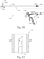
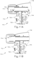
- FIGS. 10-12 show a fourth exemplary ultrasonic surgical instrument (710) including a fourth mechanical lockout assembly (744).
- Instrument (710) of the present example comprises a first modular assembly shown as a handle assembly (712), a second modular assembly shown as a shaft assembly (714), an end effector (716), a body (718), a pistol grip (720), energy control buttons (722), a trigger (724), an ultrasonic transducer (726), an ultrasonic blade (728), a clamp arm (730), a clamp pad (732), an outer tube (734), an inner tube (736), an ultrasonic waveguide (738), and a rotation knob (742).
- FIGS. 11A-11B show instrument (710) as including a mechanical lockout assembly (744).
- Mechanical lockout assembly (744) includes a barrier (746) that translates between a locked configuration and an unlocked configuration.
- Barrier (746) may translate within a molded track (747), which may be integrally formed as a unitary piece together with body (718).
- Barrier (746) includes at least one body portion (748) with at least one aperture (752) being disposed within body portion (748).
- FIGS. 11A-11B show two apertures (752).
- Barrier (746) is shown as a lockout slide that is disposed within handle assembly (712).
- Handle assembly (712) includes energy control buttons (722) separated by a passageway (754) from switches (756).
- FIG. 11A shows instrument (710) in the locked configuration, where body portion (748) contacts and translates body portion (750) that is disposed between energy control buttons (722) and switches (756).
- barrier (746) prevents the energy control button (722) from being depressed. This prevents switches (756) from activating instrument (710).
- compression spring (764) is in an extended state.
- barrier (746) is positioned such that apertures (752) are not interposed between buttons (722) and corresponding switches (756). Barrier (746) thus prevents buttons (722) from activating corresponding switches (756), thereby preventing activation of instrument (710).
- FIG. 12 depicts a schematic cross-sectional view of FIG. 11A in the locked configuration.
- FIG. 11B shows instrument (710) in an unlocked configuration, where apertures (752) are disposed between energy control buttons (722) and switches (756) enabling switches (756) to activate instrument (710).
- barrier (746) In moving to the unlocked configuration, barrier (746) is pushed downwards into passageway (754) extending between energy control buttons (722) and switches (756). With barrier (746) in a downward position, apertures (752) are positioned between buttons (722) and corresponding switches (756), thereby providing clearance for buttons (722) to activate corresponding switches (756).
- a tab (758) presses lockout slide down allowing energy control buttons (722) to contact switches (756).
- Tab (758) may be formed in outer tube (734) or be part of an outer tube overmold.
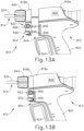
- FIGS. 13A-13B show a fifth exemplary ultrasonic surgical instrument (810) including a fifth mechanical lockout assembly (844).
- Instrument (810) of the present example comprises a first modular assembly shown as a first portion of handle assembly (812), a second modular assembly shown as a second portion of handle assembly and a shaft assembly (814), a body (818a, 818b), a pistol grip (820), energy control buttons (822), a trigger (824), an ultrasonic transducer (826), an outer tube (834), and a rotation knob (842).
- FIG. 13A shows instrument (810) in a locked configuration, where a mechanical lockout assembly (844) prevents activation of instrument (810) if shaft assembly (814) is not completely coupled with handle assembly (812).
- Handle assembly (812) may include at least a portion of energy control buttons (822).
- energy control buttons (822) maybe split into shaft and handle portions (846, 848), or have energy control buttons (822) entirely with shaft assembly (814).
- shaft portions (846) of energy control buttons (822) may be coupled with shaft assembly (814) while handle portions (848) of energy control buttons (822) may be coupled with handle assembly (812). Misalignment of shaft and handle portions (846, 848) of energy control buttons (822) prevents switches (856) from activating instrument (810).
- FIG. 13B shows instrument (810) in an unlocked configuration, where shaft assembly (814) is completely coupled with handle assembly (812).
- mechanical lockout assembly (844) allows energy control button (822) to contact switch (856), allowing an operator to activate instrument (810).
- Alignment of shaft and handle portions (846, 848) of energy control buttons (822) enable switches (856) to activate instrument (810).
- Switches (856), which may be dome switches according to an exemplary embodiment, may be in electrical communication with a printed circuit board (“PCB”) and may remain within handle assembly (812).
- Memory such as EEPROM, may be disposed within handle assembly (812), and cannot activate energy control buttons (822) without shaft assembly (814) completely installed.
- Switches (856) may be recessed within handle assembly (812) to prevent unintentional actuation.
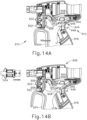
- FIGS. 14A-15D show a sixth exemplary ultrasonic surgical instrument (910) including a sixth mechanical lockout assembly (944).
- Instrument (910) of the present example comprises a first modular assembly shown as a handle assembly (912), a second modular assembly shown as a shaft assembly (914), a body (918), a pistol grip (920), at least one energy control button (922), a trigger (924), an ultrasonic transducer (926), and an outer tube (934).
- handle assembly (912) includes switches (956) that are configured to be actuated by energy control buttons (922).
- Mechanical lockout assembly (944) includes a closure lever link (946) operatively coupled with trigger (924) in handle assembly (912).
- Handle assembly (912) includes stop features (948) that may limit motion of closure lever link (946), if desired. Stop features (948) may be integrally formed as a unitary piece with body (918) of handle assembly (912) or may be distinct components coupled with body (918) of handle assembly (912).
- closure lever link (946) is coupled at a first end with body (918) at a first rotation point (950).
- Closure lever link (946) is coupled at a second end with trigger (924) at a second rotation point (952).
- trigger (924) is coupled with body (918) at a third rotation point (954).
- FIG. 14A shows instrument (910) in an unlocked configuration, with FIG. 15A showing a detailed view of handle assembly (912) where shaft assembly (914) is subsequently inserted therethrough.
- angle alpha ( ⁇ ) between first rotation point (950) and a point of trigger (924) is less than 180 degrees.
- trigger (924) is rotated/translated distally as shown by the arrow. It is also envisioned that instrument (910) may be initially in the locked configuration, as will be described in connection with FIG. 15B .
- FIG. 14B shows where the operator pulls closure lever link (946) beyond the unlocked configuration, which functions as the normal operating position, with FIG. 15B showing a detailed view of shaft assembly (914) being actively inserted into handle assembly (912).
- FIG. 15B shows a detailed view of shaft assembly (914) being actively inserted into handle assembly (912).
- closure lever link (946) is pulled over center in a first direction. Pulling closure lever link (946) over center prevents closure lever link (946) from being rotated closed.
- angle beta ( ⁇ ) between first rotation point (950) and a point of trigger (924) is greater than 180 degrees. When trigger (924) is effectively locked, this prevents the operator from clamping on tissue with an end effector disposed at a distal end of shaft assembly (914) until shaft assembly (914) is fully seated in handle assembly (912).
- FIGS. 14C and 15C show a second locked configuration, where shaft assembly (914) is inserted into instrument (910), which pushes yoke (958) proximally, and relieves closure lever link (946) from being over center.
- Yoke (958) couples trigger assembly of handle with the clamp arm closure driver of shaft assembly (914).
- angle theta ( ⁇ ) between first rotation point (950) and a point of trigger (924) is approximately 180 degrees.
- Mechanical lockout assembly (944) maintains the locked configuration, until shaft assembly (914) is fully seated with handle assembly (912).
- FIGS. 14D and 15D show the unlocked configuration when shaft assembly (914) is completely coupled with handle assembly (912).
- FIG. 14D shows that activation of trigger (924) causes closure lever link (946) to rotate in second direction that is opposite first direction.
- trigger (924) is transitioned to the unlocked configuration. This allows trigger (924) to be actuated to thereby actuate a clamp arm of an end effector.
- Mechanical lockout assembly (944) effectively locks out use of a clamp arm assembly.
- angle alpha ( ⁇ ) between first rotation point (950) and a point of trigger (924) is less than 180 degrees.
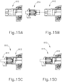
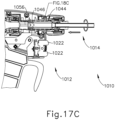
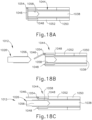
- FIGS. 16-18C show a seventh exemplary ultrasonic surgical instrument (1010) including a seventh mechanical lockout assembly (1044).
- Instrument (1010) of the present example comprises a first modular assembly shown as a handle assembly (1012), a second modular assembly shown as a shaft assembly (1014), an end effector (1016), a body (1018), a pistol grip (1020), energy control buttons (1022), a trigger (1024), an ultrasonic transducer (1026), an ultrasonic blade (1028), a clamp arm (1030), a clamp pad (1032), an outer tube (1034), an inner tube (1036), an ultrasonic waveguide (1038), and a rotation knob (1042).
- FIGS. 17A-17C show instrument (1010) as including a mechanical lockout assembly (1044).
- Mechanical lockout assembly (1044) includes a one-way door (1046) that is configured to be opened by coupling handle assembly (1012) with shaft assembly (1014).
- mechanical lockout assembly (1044) is coupled with shaft assembly (1014), such that shaft assembly (1014) and mechanical lockout assembly (1044) are coupled together, however, this is not required.
- FIGS. 17A and 18A show shaft assembly (1014) approaching handle assembly (1012), with one-way door (1046) blocking access to threaded bore (1058) at the proximal end of acoustic waveguide (1038) of shaft assembly (1014).
- FIGS. 17B and 18B show shaft assembly (1014) partially coupled with handle assembly (1012), with one-way door (1046) still preventing threaded stud (1056) of ultrasonic transducer (1026) from reaching threaded bore (1058) at the proximal end of acoustic waveguide (1038).
- translatable jacket (1048) translates relative to one-way door (1046) pushing one-way door (1046) to the unlocked configuration (shown in FIGS. 17C and 18C ) allowing complete coupling of threaded stud (1056) with threaded bore (1058), thereby completing an acoustic coupling between ultrasonic transducer (1026) and ultrasonic waveguide (1038).
- outer tube (1034) includes a rotary component (1050) and a yoke (1052), however, rotary component (1050) and yoke (1052) may be integrally formed as a unitary piece or fixably coupled together using a variety of known attachment methods. As shown, rotation of rotary component (1050) of outer tube (1034) causes yoke (1052) of outer tube (1034) and translatable jacket (1048) to translate towards handle assembly (1012).
- Yoke (1052) may be threadably coupled with rotary component (1050), with yoke (1052) being keyed to shaft assembly (1014), such that yoke (1052) translates relative to shaft assembly (1014) without rotating relative to shaft assembly (1014).
- Rotation of rotary component (1050) drives yoke (1052) proximally, allowing translatable jacket (1048) to translate proximally, which in turn allows one-way door (1046) to rotate open at a hinge point (1054).
- FIGS. 17C and 18C show the unlocked configuration where shaft assembly (1014) is completely coupled with handle assembly (1012), and with transducer (1026) fully coupled with waveguide (1038), thereby allowing ultrasonic activation of ultrasonic blade (1028).
- FIGS. 17C and 18C show that once one-way door (1046) is open, externally threaded stud (1056) of ultrasonic transducer (1026) may be threadably coupled with an internally threaded proximal recess (1058) of ultrasonic waveguide (1038).
- ultrasonic transducer (1026) is able to acoustically couple with ultrasonic waveguide (1038).
- One-way door (1046) ensures that the acoustic drivetrain may only be assembled when shaft assembly (1014) is completely coupled with handle assembly (1012).
- clamp arm (1030) For instrument (1010), which includes clamp arm (1030) that is assembled by the operator to handle assembly (1012), it is beneficial that clamp arm (1030) be precisely aligned with ultrasonic blade (1028).
- Mechanical lockout assembly (1044) incorporates a means to lock out the acoustic drivetrain, so that ultrasonic blade (1028) cannot be activated by energy control buttons (1022) until shaft assembly (1014) is completely coupled with handle assembly (1012). Additionally, if there is not full rotary engagement, translatable jacket (1048) falls short and cannot open one-way door (1046), and as a result, handle assembly (1012) contacts one-way door (1046) and does not thread ultrasonic waveguide (1038). This prevents use of trigger (1024) that drives the clamp arm (1030) and champ pad (1032) toward the ultrasonic blade (1028), which provides tactile feedback to the operator of the inoperability of instrument (1010) due to being in the locked configuration.
- FIGS. 19-21D show an eighth exemplary ultrasonic surgical instrument (1110) including an eighth mechanical lockout assembly (1144).
- Instrument (1110) of the present example comprises a first modular assembly shown as a handle assembly (1112), a second modular assembly shown as a shaft assembly (1114), an end effector (1116), a body (1118), a pistol grip (1120), energy control buttons (1122), a trigger (1124), an ultrasonic transducer (1126), an ultrasonic blade (1128), a clamp arm (1130), a clamp pad (1132), an outer tube (1134), an inner tube (1136), a rotation knob (1142), and a shaft coupler (1143).
- FIG. 20 shows that instrument (1110) includes a mechanical lockout assembly (1144).
- Mechanical lockout assembly (1144) includes a coupling device (1146) operatively coupled to handle assembly (1112) using a retention member (1148) that restricts distal translation of a head portion (1152) of coupling device (1146). More specifically, since coupling device (1146) translates longitudinally to communicate a clamp arm closure motion from trigger (1124) to clamp arm actuator of shaft assembly (1114), coupling device (1146) subsequently translates proximally from the position shown in FIG. 20 . Subsequently, coupling device (1146) translates distally back to the position shown in FIG. 20 . In this manner, retention member (1148) restricts distal translation of coupling device (1146).
- Clamp arm actuating member translates relative to the remainder of shaft assembly (1114) to drive pivotal movement of clamp arm (1130) toward and away from ultrasonic blade (1128).
- shaft assembly (1114) couples with handle assembly (1112), projection (1150) that is shown integral with clamp arm actuating member of shaft assembly (1114), enters track (1154) to suitably couple shaft assembly (1114) with handle assembly (1112).
- FIGS. 21A-21D show four exemplary coupling devices (1156, 1158, 1160, 1162), configured to be used with mechanical lockout assembly (1144) of instrument (1110).
- Coupling devices (1146, 1156, 1158, 1160, 1162) translate longitudinally in response to pivotal movement of trigger (1124).
- Coupling devices (1146, 1156, 1158, 1160, 1162) also couple trigger (1124) with the clamp arm closure actuator of shaft assembly (1114).
- Clamp arm closure actuator includes projection (1150).
- clamp arm (1130) does not move at all in response to movement of trigger (1124).
- Coupling devices (1146, 1156, 1158, 1160, 1162) move proximally to actuate clamp arm (1130).
- each coupling device (1156, 1158, 1160, 1162) includes a guide track (1164, 1166, 1168, 1170) configured to engage with projection (1150) shown in FIG. 20 of shaft assembly (1114).
- Guide tracks (1154, 1164, 1166, 1168, 1170) of respective coupling devices (1146, 1156, 1158, 1160, 1162) are configured to translate and rotate shaft assembly (1114) using the interaction between projection (1150) and guide track (1154, 1164, 1166, 1168, 1170) from the locked configuration when shaft assembly (1114) is partially coupled with handle assembly (1112) to the unlocked configuration when shaft assembly (1114) is completely coupled with handle assembly (1112).
- FIG. 21A shows a coupling device (1156) with a guide track (1164) disposed within a body portion (1172) and a head portion (1174) that is configured to be retained by retention member (1148), and an aperture (1175) extending therethrough.
- Coupling device (1156) is similar to coupling device (1146) shown in FIG. 20 , however, coupling device (1156) additionally includes a detent (1176) to guide track (1164) to ensure that trigger (1124) and clamp arm (1130) are non-responsive until projection (1150) is fully seated and fully rotated.
- Detent (1176) provides tactile feedback to the operator indicating to the operator that shaft assembly (1114) is fully coupled; and to prevent inadvertent decoupling of the shaft assembly (1114) after shaft assembly (1114) is fully coupled.
- FIGS. 21B-21D show three exemplary embodiments of track patterns (1166, 1168, 1170) that result in various changes to the opening/closing of clamp arm (1130) during operation when shaft assembly (1114) is not completely coupled with handle assembly (1112).
- FIG. 21B shows a coupling device (1158) as including a guide track (1166) disposed within a body portion (1178) and a head portion (1180) that is configured to be retained by retention member (1148), and an aperture (1181) extending therethrough.
- FIG. 21B shows coupling device (1158) as including an extra relief portion (1182) prior to seating position, which allows clamp arm (1130) to open but not to close, thereby alerting the operator of a potential misalignment. As shown, extra relief portion (1180) is longer than the length of travel.
- FIG. 21C shows a coupling device (1160) with a guide track (1168) disposed within a body portion (1184) and head portion (1186) that is configured to be retained by retention member (1148), and an aperture (1187) extending therethrough.
- FIG. 21B shows coupling device (1158) as including an extra relief portion (1188) positioned beyond the normal seating position allowing clamp arm (1130) to close if not fully rotated, but not allowing clamp arm (1130) to return back, thereby alerting the operator of a potential misalignment. As shown, extra relief portion (1180) is longer than the length of travel. Distal movement of the clamp arm actuator of shaft assembly (1114) provides pivotal movement of clamp arm (1130) toward ultrasonic blade (1128).
- FIG. 21D shows a coupling device (1162) as including a guide track (1170) disposed within a body portion (1190) and head portion (1192) that is configured to be retained by retention member (1148), and an aperture (1196) extending therethrough.
- FIG. 21D shows guide track (1170) as being angled, so as to rotate while advancing. To be fully seated, projection (1150) of shaft coupler (1143) is fully rotated on coupling device (1162).
- Coupling device (1162) may additionally include a stop member (1194) in guide track (1170) to ensure that trigger (1124) and clamp arm (1130) are non-responsive until projection (1150) is fully seated and fully rotated, such that instrument (1110) is switched from the locked configuration to the unlocked configuration.
- detent (1194) provides tactile feedback to the operator and prevents inadvertent decoupling. Unlike the FIG. 21A the curved configuration of guide track (1170) causes the coupling device to release projection (1150) if the operator actuates trigger (1124), thereby translating coupling device (1162) if projection (1150) is not fully seated behind detent (1194). Coupling device (1162) moves proximally to actuate clamp arm (1130).
- Instrument (1110) prevents outer shaft (1134) from moving forwards/backwards, thereby preventing closing of clamp arm (1130) when shaft assembly (1114) is not fully rotated into position.
- Mechanical lockout assembly (1144) and its various coupling devices (1146, 1156, 1158, 1160, 1162) prevent responsiveness of clamp arm (1130) to movement of trigger until shaft assembly (1114) is fully seated.
- Mechanical lockout assembly (1144) using a shaft coupler (1143) with projection (1150) couples with guide tracks (1154, 1164, 1166, 1168, 1170) of respective coupling devices (1146, 1156, 1158, 1160, 1162) providing immediate and clear feedback to the operator of a misalignment between shaft assembly (1114) and handle assembly (1112).
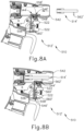
- FIGS. 22-28 show a ninth exemplary ultrasonic surgical instrument (1210) including a ninth mechanical lockout assembly (1244).
- Instrument (1210) of the present example comprises a first modular assembly shown as a handle assembly (1212), a second modular assembly shown as a shaft assembly (1214), an end effector (1216), a body (1218), a pistol grip (1220), energy control buttons (1222), a trigger (1224), an ultrasonic transducer (1226), an ultrasonic blade (1228), a clamp arm (1230), a clamp pad (1232), an outer tube (1234), an inner tube (1236), and a rotation knob (1242).
- FIG. 23 shows instrument (1210) as including a mechanical lockout assembly (1244).
- mechanical lockout assembly (1244) includes an outer tube collar (1246) and a bayonet collar (1248), and a rotation collar (1249) (see FIG. 28 ).
- Outer tube collar (1246) is integrated into handle assembly (1212).
- Outer tube collar (1246) may rotate within handle assembly (1212), and may also translate within handle assembly (1212).
- Outer tube collar (1246) is part of a clamp arm drive assembly that couples trigger (1224) of handle assembly (1212) with outer tube (1234) of shaft assembly (1214). When trigger (1224) is actuated, outer tube collar (1246) translates longitudinally.
- outer tube collar (1246) When outer tube collar (1246) translates, the translation of outer tube collar (1246) is communicated to outer tube (1234) of shaft assembly (1214). When outer tube (1234) of shaft assembly (1214) translates, clamp arm (1230) pivots toward and away from ultrasonic blade (1228).
- Bayonet collar (1248) may be removably coupled with shaft assembly (1214), and is fixedly secured to the proximal end of outer tube (1234) of shaft assembly (1214).
- Rotation collar (1249) (see FIG. 28 ) is integrated into handle assembly (1212) as part of rotation knob (1242) that rotates entire shaft assembly (1214) relative to handle assembly (1212). Rotation collar (1249) rotates relative to handle assembly (1212), but does not translate relative to handle assembly (1212).
- FIG. 24 shows outer tube collar (1246) as including a spring leg (1250) that includes a distal end (1252). Distal end (1252) of spring leg (1250) includes a resilient interference tab (1254) with a contact surface (1255). Spring leg (1250) also includes a cam surface (1256) that acts as a ramp, which will be discussed in greater detail below with reference to FIGS. 26A-27C .
- Outer tube collar (1246) also includes first and second passageways (1258,1260), which extend in a generally longitudinal direction relative to outer tube collar (1246), and a third passageway (1262) having a width of W1 that extends generally transverse to the longitudinal direction of outer tube collar (1246). A fourth passageway, similar to third passageway (1262), is hidden from view.
- Outer tube collar (1246) also includes cutouts (1264) as will be discussed with reference to FIG. 26B .
- Outer tube collar (1246) may be threadably coupled to a portion of clamp arm drivetrain using threaded portion (1266). Thus, outer tube collar (1246) translates with clamp arm drivetrain.
- FIG. 25 shows bayonet collar (1248) as including at least one bayonet projection (1268), with two being shown in FIGS. 27A-27C , configured to contact cam surface (1256) of spring leg (1250) as bayonet collar (1248) is rotated relative to outer tube collar (1246) from a locked configuration to an unlocked configuration.
- Bayonet collar (1248) also includes protrusions (1270) that are configured to be received in cutouts (1264) as shown in FIG. 26C , to provide a detent coupling.
- Bayonet projection (1268) serves two purposes. First, bayonet projection (1268) pulls down interference tab (1254) to disengage interference tab (1254) from a lateral aperture (1276) in rotation collar (1249) shown in FIG.
- bayonet projection (1268) provides a coupling between bayonet collar (1248) and outer tube collar (1246), such that longitudinal motion of outer tube collar (1246) is communicated to bayonet collar (1248).
- interference tab (1254) is disengaged from lateral aperture (1276) of rotation collar (1249) (see FIG. 28 )
- movement of the clamp arm actuation assembly components within handle assembly (1212) is communicated to outer tube (1234) of shaft assembly (1214) via the engagement between outer tube and bayonet collars (1246, 1248), as provided by interference tab (1254).
- FIGS. 26A , 27A , and 28 show instrument (1210) in the locked configuration, where handle assembly (1212) and shaft assembly (1214) are not fully coupled together.
- Rotation collar (1249) (see FIG. 28 ), includes a lateral aperture (1276) that receives interference tab (1254) to provide the locked configuration.
- interference tab (1254) of outer tube collar (1246) is positioned in lateral aperture (1276) of rotation collar (1249)
- outer tube collar (1246) is unable to translate.
- trigger (1224) cannot be pivoted
- clamp arm (1230) cannot be pivoted toward ultrasonic blade (1228).
- shaft assembly (1214) has been fully inserted longitudinally into handle assembly (1212), shown by bayonet collar (1248) contacting outer tube collar (1246).
- shaft assembly (1212) has not yet been rotated relative to handle assembly (1212) to fully seat shaft assembly (1214). More specifically, in the locked configuration, resilient interference tab (1254) of outer tube collar (1246) is not deflected inwardly, but instead is captured in lateral aperture (1276) of rotation collar (1249) shown in FIG. 28 .
- mechanical lockout assembly (1244) prevents the operator from activating instrument (1210) using clamp arm closure trigger (1224).
- a central aperture (1247) extends through both outer tube collar (1246) and bayonet collar (1248) to receive an ultrasonic waveguide (not shown).
- FIGS. 26B and 27B show instrument (1210) transitioning between the locked configuration and the unlocked configurations, with the operator still being prohibited from actuating trigger (1224).
- resilient interference tab (1254) is being pulled inward and outward of lateral aperture (1276) in rotation collar (1249) when bayonet collar (1248) is rotated.
- Bayonet projection (1268) rides along cam surface (1256) as bayonet collar (1248) is rotated, which pulls cam surface (1256) and the rest of resilient interference tab (1254) inward.
- cam surface (1256) is integrally formed as a unitary piece together with resilient interference tab (1254). More specifically, bayonet projection (1268) includes a radially extending component which travels through passageways (1258, 1262) and a proximally extending component which pulls down the spring leg (1250) supporting resilient interference tab (1254).
- FIGS. 26C and 27C show instrument (1210) in the unlocked configuration, where handle assembly (1212) and shaft assembly (1214) are completely coupled together, such that the operator is able to activate instrument (1210) using trigger (1222).
- interference tab (1254) is pulled out of lateral aperture (1276) of rotation collar (1249), outer tube collar (1246) is then free to translate, thereby enabling pivotal movement of trigger (1224), thereby enabling closure of clamp arm (1230) toward ultrasonic blade (1228).
- bayonet projections (1268) on bayonet collar (1248) push resilient interference tab (1254) inwards towards a center of outer tube collar (1246), enabling the shaft assembly (1214) including clamp arm (1230) to function.
- Outer tube (1234) translates relative to the rest of shaft assembly (1214) to provide pivotal movement of clamp arm (1230) toward/away from ultrasonic blade (1228).
- the operator rotates shaft assembly (1214) to fully assemble instrument (1210), the operator would want to grasp rotation knob (1242) and hold it stationary.
- the various instruments described above may be used in a variety of kinds of surgical procedures.
- the instruments described above may be used to perform liver resection, colorectal surgical procedures, gynecological surgical procedures, and/or various other kinds of surgical procedures.
- Various other kinds of procedures and ways in which the instruments described above may be used will be apparent to those of ordinary skill in the art in view of the teachings herein.
- Versions of the devices described above may have application in conventional medical treatments and procedures conducted by a medical professional, as well as application in robotic-assisted medical treatments and procedures.
- various teachings herein may be readily incorporated into a robotic surgical system such as the DAVINCI TM system by Intuitive Surgical, Inc., of Sunnyvale, California.
- DAVINCI TM system by Intuitive Surgical, Inc., of Sunnyvale, California.
- teachings herein may be readily combined with various teachings of U.S. Pat. No. 6,783,524, entitled "Robotic Surgical Tool with Ultrasound Cauterizing and Cutting Instrument," published August 31, 2004 .
- Versions described above may be designed to be disposed of after a single use, or they can be designed to be used multiple times. Versions may, in either or both cases, be reconditioned for reuse after at least one use. Reconditioning may include any combination of the steps of disassembly of the device, followed by cleaning or replacement of particular pieces, and subsequent reassembly. In particular, some versions of the device may be disassembled, and any number of the particular pieces or parts of the device may be selectively replaced or removed in any combination. Upon cleaning and/or replacement of particular parts, some versions of the device may be reassembled for subsequent use either at a reconditioning facility, or by an operator immediately prior to a procedure.
- reconditioning of a device may utilize a variety of techniques for disassembly, cleaning/replacement, and reassembly. Use of such techniques, and the resulting reconditioned device, are all within the scope of the present application.
- versions described herein may be sterilized before and/or after a procedure.
- the device is placed in a closed and sealed container, such as a plastic or TYVEK bag.
- the container and device may then be placed in a field of radiation that can penetrate the container, such as gamma radiation, x-rays, or high-energy electrons.
- the radiation may kill bacteria on the device and in the container.
- the sterilized device may then be stored in the sterile container for later use.
- a device may also be sterilized using any other technique known in the art, including but not limited to beta or gamma radiation, ethylene oxide, or steam.
Landscapes
- Health & Medical Sciences (AREA)
- Surgery (AREA)
- Life Sciences & Earth Sciences (AREA)
- Engineering & Computer Science (AREA)
- Heart & Thoracic Surgery (AREA)
- Nuclear Medicine, Radiotherapy & Molecular Imaging (AREA)
- Biomedical Technology (AREA)
- Medical Informatics (AREA)
- Molecular Biology (AREA)
- Animal Behavior & Ethology (AREA)
- General Health & Medical Sciences (AREA)
- Public Health (AREA)
- Veterinary Medicine (AREA)
- Mechanical Engineering (AREA)
- Dentistry (AREA)
- Ophthalmology & Optometry (AREA)
- Surgical Instruments (AREA)
Claims (11)
- Chirurgisches Ultraschallinstrument (110), umfassend:(a) eine Griffanordnung (112), die mindestens ein Benutzereingabemerkmal aufweist;(b) einen Ultraschallwandler (126), der an der Griffanordnung gelagert ist;(c) eine Schaftanordnung (114), die dazu ausgelegt ist, entfernbar mit der Griffanordnung zu koppeln, wobei die Schaftanordnung einen distalen Endabschnitt aufweist, wobei die Schaftanordnung ferner aufweist:(i) einen Endeffektor (116), der sich distal von dem distalen Endabschnitt erstreckt, und(ii) einen Ultraschallwellenleiter (138), der dazu ausgelegt ist, akustisch mit dem Ultraschallwandler gekoppelt zu werden; und(d) eine mechanische Verriegelungsanordnung (544), die dazu ausgelegt ist, sich zwischen mindestens einer nicht verriegelten Auslegung und einer verriegelten Auslegung zu bewegen,wobei in der verriegelten Auslegung die Griffanordnung und die Schaftanordnung nur teilweise miteinander gekoppelt sind, was den Benutzer physikalisch daran hindert, das Instrument mithilfe des Benutzereingabemerkmals zu aktivieren, undwobei in der nicht verriegelten Auslegung die Griffanordnung und die Schaftanordnung vollständig miteinander gekoppelt sind, was dem Benutzer ermöglicht, das Instrument mithilfe des Benutzereingabemerkmals zu aktivieren.
- Chirurgisches Ultraschallinstrument nach Anspruch 1, wobei in der verriegelten Auslegung die mechanische Verriegelungsanordnung verhindert, dass das Benutzereingabemerkmal einen Auslöser (124) der Griffanordnung aktiviert, der funktional mit dem Endeffektor gekoppelt ist, wobei das Verhindern der Aktivierung des Auslösers den Benutzer daran hindert, Gewebe mit dem Endeffektor einzuklemmen.
- Chirurgisches Ultraschallinstrument nach Anspruch 1 oder Anspruch 2, wobei der Endeffektor eine Ultraschallklinge (128) umfasst, wobei in der verriegelten Auslegung die mechanische Verriegelungsanordnung verhindert, dass das Benutzereingabemerkmal mindestens einen Energiesteuerungsknopf (122) aktiviert, der an der Griffanordnung angeordnet ist, was den Benutzer daran hindert, die Ultraschallklinge zu aktivieren.
- Chirurgisches Ultraschallinstrument nach einem vorhergehenden Anspruch, wobei eine Feder (664) die mechanische Verriegelungsanordnung aus der nicht verriegelten Auslegung in die verriegelte Auslegung schiebt, wenn die Schaftanordnung von der Griffanordnung entfernt wird.
- Chirurgisches Ultraschallinstrument nach Anspruch 1, wobei die Griffanordnung das Benutzereingabemerkmal aufweist, das mindestens einen Schalter (856) und einen ersten Abschnitt (848) eines Energiesteuerknopfes (822) aufweist, wobei die Schaftanordnung einen zweiten Abschnitt (846) eines Energiesteuerknopfes (822) aufweist, wobei in der verriegelten Auslegung, in der die Schaftanordnung teilweise mit der Griffanordnung gekoppelt ist, der Versatz des ersten und zweiten Abschnitts des Energiesteuerknopfes verhindert, dass der Schalter das Instrument aktiviert, und wobei in der nicht verriegelten Auslegung, in der die Schaftanordnung vollständig mit der Griffanordnung gekoppelt ist, die Übereinstimmung des ersten und des zweiten Abschnitts des Energiesteuerknopfes ermöglicht, dass der Schalter das Instrument aktiviert.
- Chirurgisches Ultraschallinstrument nach Anspruch 1, wobei die Griffanordnung das Benutzereingabemerkmal aufweist, wobei das Benutzereingabemerkmal einen Auslöser (924) aufweist, wobei die mechanische Verriegelungsanordnung ferner eine Verschlusshebelverbindung (946) aufweist, die funktional mit dem Auslöser gekoppelt ist, wobei in der verriegelten Auslegung, in der die Schaftanordnung teilweise mit der Griffanordnung gekoppelt ist, die Verschlusshebelverbindung über das Zentrum in eine erste Richtung gezogen wird, was verhindert, dass die Verschlusshebelverbindung zugedreht wird, was verhindert, dass der Auslöser betätigt wird, was verhindert, dass der Endeffektor geschlossen wird, und wobei in der nicht verriegelten Auslegung, in der die Schaftanordnung vollständig mit der Griffanordnung gekoppelt wird, der Einsatz der Schaftanordnung bewirkt, dass die Verschlusshebelverbindung in eine zweite Richtung, die der ersten Richtung entgegengesetzt ist, dreht, was erlaubt, dass der Auslöser betätigt werden kann, was es dem Endeffektor ermöglicht, sich zu schließen.
- Chirurgisches Ultraschallinstrument nach Anspruch 1, wobei die mechanische Verriegelungsanordnung ferner eine Einwegtür (1046) aufweist, die dazu ausgelegt ist, durch Koppeln der Schaftanordnung mit der Griffanordnung geöffnet zu werden, wobei in der verriegelten Auslegung, in der die Schaftanordnung teilweise mit der Griffanordnung gekoppelt ist, die Einwegtür verhindert, dass ein Verbindungsabschnitt des Ultraschallwandlers einen Verbindungsabschnitt eines proximalen Endes des Ultraschallwellenleiters erreicht, wobei beim Bewegen aus der verriegelten Auslegung in die nicht verriegelte Auslegung, wenn eine Außenhülle gedreht wird, eine verschiebbare Hülle (1048), die durch Gewinde mit der Außenhülle gekoppelt ist, sich in Längsrichtung bezogen auf die Einwegtür bewegt und die Einwegtür in eine offene Position schwenkt, was es den Verbindungsabschnitten des Ultraschallwandlers und dem Ultraschallwellenleiter ermöglicht, akustisch zu koppeln, und wobei, in der nicht verriegelten Auslegung, in der die Schaftanordnung vollständig mit der Griffanordnung gekoppelt ist, der Endeffektor mithilfe des Benutzereingabemerkmals betätigt werden kann.
- Chirurgisches Ultraschallinstrument nach Anspruch 1, wobei ein proximaler Abschnitt der Schaftanordnung einen Vorsprung (1150) aufweist, wobei die mechanische Verriegelungsanordnung eine Kopplungseinrichtung (1146) aufweist, die funktional mit der Griffanordnung gekoppelt ist, und wobei die Kopplungseinrichtung eine Führungsspur (1164, 1166, 1168, 1170) aufweist, die dazu ausgelegt ist, die Schaftanordnung zu bewegen und zu drehen mithilfe des Zusammenwirkens zwischen dem Vorsprung der Schaftanordnung und der Führungsspur der Kopplungseinrichtung aus der verriegelten Auslegung, in der die Schaftanordnung teilweise mit der Griffanordnung gekoppelt ist, in die nicht verriegelte Auslegung, in der die Schaftanordnung vollständig mit der Griffanordnung gekoppelt ist, wobei sich vorzugsweise die Kopplungseinrichtung in Reaktion auf die Schwenkbewegung eines Auslösers (1124) in Längsrichtung bewegt, und wobei die Kopplungseinrichtung den Auslöser funktional mit dem Klemmarm der Schaftanordnung koppelt.
- Chirurgisches Ultraschallinstrument nach Anspruch 1, wobei die mechanische Verriegelungsanordnung aufweist:(i) einen Außenrohrkragen (1246), der mit der Griffanordnung gekoppelt ist, wobei der Außenrohrkragen einen Federschenkel (1250) aufweist, der ein distales Ende (1252) aufweist, wobei das distale Ende des Federschenkels eine elastische Eingrifflasche (1254) aufweist; und(ii) einen Bajonettkragen (1248), der mit der Schaftanordnung gekoppelt ist, wobei der Bajonettkragen einen Bajonettvorsprung (1268) aufweist, der dazu ausgelegt ist, eine Nockenoberfläche (1256) des Federschenkels zu kontaktieren, wenn der Bajonettkragen bezogen auf den Außenrohrkragen aus der verriegelten Auslegung in die nicht verriegelte Auslegung gedreht wird; und(iii) einen Drehkragen (1249), der eine Öffnung (1276) aufweist,wobei in der verriegelten Auslegung, in der die Schaftanordnung teilweise mit der Griffanordnung gekoppelt ist, die Eingrifflasche des Außenrohrkragens nach außen in die Öffnung des Drehkragens ablenkt, was die Aktivierung des Instruments verhindert, undwobei in der nicht verriegelten Auslegung, in der die Schaftanordnung vollständig mit der Griffanordnung gekoppelt ist, der Bajonettvorsprung die Nockenoberfläche der Eingrifflasche kontaktiert, um die Eingrifflasche einwärts abzulenken, was die Aktivierung des Instruments ermöglicht.
- Chirurgisches Ultraschallinstrument nach Anspruch 1, wobei das Benutzereingabemerkmal mindestens einen Energiesteuerungsknopf (522) aufweist, der durch einen Durchlass (554) von einem Schalter (556) in der Griffanordnung getrennt ist;
und wobei die mechanische Verriegelung ferner umfasst:
eine Sperre (546), die einen Körperabschnitt (548, 550) und mindestens eine Öffnung (552) aufweist, die sich mindestens teilweise durch den Körperabschnitt erstreckt, wobei sich die Sperre in dem Durchgang zwischen der verriegelten Auslegung und der nicht verriegelten Auslegung horizontal bewegt,wobei in der verriegelten Auslegung der Körperabschnitt in dem Durchgang zwischen dem Energiesteuerungsknopf und dem Schalter angeordnet ist, was verhindert, dass der Schalter das Instrument aktiviert, undwobei in der nicht verriegelten Auslegung die Öffnung in dem Durchgang zwischen dem Energiesteuerungsknopf und dem Schalter angeordnet ist, und mindestens einer des Energiesteuerungsknopfes oder des Schalters sich mindestens teilweise durch die Öffnung der Sperre erstreckt und direkten physikalischen Kontakt zu dem anderen des Energiesteuerungsknopfes oder des Schalters durch die Öffnung herstellt, was ermöglicht, dass der Schalter das Instrument aktiviert. - Chirurgisches Ultraschallinstrument nach Anspruch 10, wobei eine Feder den Körperabschnitt der Sperre aus der nicht verriegelten Auslegung in die verriegelte Auslegung schiebt, wenn die Schaftanordnung von der Griffanordnung entfernt wird.
Applications Claiming Priority (1)
| Application Number | Priority Date | Filing Date | Title |
|---|---|---|---|
| US15/951,788 US11051841B2 (en) | 2018-04-12 | 2018-04-12 | Mechanical lockout for ultrasonic surgical instrument |
Publications (3)
| Publication Number | Publication Date |
|---|---|
| EP3552566A1 EP3552566A1 (de) | 2019-10-16 |
| EP3552566C0 EP3552566C0 (de) | 2023-07-19 |
| EP3552566B1 true EP3552566B1 (de) | 2023-07-19 |
Family
ID=66105277
Family Applications (1)
| Application Number | Title | Priority Date | Filing Date |
|---|---|---|---|
| EP19168796.1A Active EP3552566B1 (de) | 2018-04-12 | 2019-04-11 | Mechanische verriegelung für chirurgisches ultraschallinstrument |
Country Status (6)
| Country | Link |
|---|---|
| US (1) | US11051841B2 (de) |
| EP (1) | EP3552566B1 (de) |
| JP (1) | JP7404265B2 (de) |
| CN (1) | CN112203602A (de) |
| BR (1) | BR112020020242A2 (de) |
| WO (1) | WO2019198035A1 (de) |
Families Citing this family (8)
| Publication number | Priority date | Publication date | Assignee | Title |
|---|---|---|---|---|
| US10624667B2 (en) * | 2016-05-20 | 2020-04-21 | Ethicon Llc | System and method to track usage of surgical instrument |
| US10945755B2 (en) | 2018-04-12 | 2021-03-16 | Ethicon Llc | Mechanical lockout for ultrasonic surgical instrument |
| US11076881B2 (en) | 2018-04-12 | 2021-08-03 | Cilag Gmbh International | Electrical lockout for ultrasonic surgical instrument |
| US11243556B2 (en) * | 2020-03-10 | 2022-02-08 | Whirlpool Corporation | Knob assembly for a cooking appliance and method of assembling |
| WO2023139481A1 (en) * | 2022-01-21 | 2023-07-27 | Covidien Lp | Ultrasonic surgical instrument |
| EP4241713A1 (de) | 2022-03-11 | 2023-09-13 | Cilag GmbH International | Elektrochirurgisches instrument mit klammerverschlusssensor |
| WO2023170645A1 (en) | 2022-03-11 | 2023-09-14 | Cilag Gmbh International | Electrosurgical instrument with clamp closure sensor |
| JP7766752B2 (ja) * | 2023-09-18 | 2025-11-10 | オリンパスメディカルシステムズ株式会社 | 処置具 |
Citations (1)
| Publication number | Priority date | Publication date | Assignee | Title |
|---|---|---|---|---|
| US20150148830A1 (en) * | 2013-11-22 | 2015-05-28 | Ethicon Endo-Surgery, Inc. | Features for coupling surgical instrument shaft assembly with instrument body |
Family Cites Families (37)
| Publication number | Priority date | Publication date | Assignee | Title |
|---|---|---|---|---|
| US5322055B1 (en) | 1993-01-27 | 1997-10-14 | Ultracision Inc | Clamp coagulator/cutting system for ultrasonic surgical instruments |
| US5980510A (en) | 1997-10-10 | 1999-11-09 | Ethicon Endo-Surgery, Inc. | Ultrasonic clamp coagulator apparatus having improved clamp arm pivot mount |
| US5873873A (en) | 1997-10-10 | 1999-02-23 | Ethicon Endo-Surgery, Inc. | Ultrasonic clamp coagulator apparatus having improved clamp mechanism |
| US6325811B1 (en) | 1999-10-05 | 2001-12-04 | Ethicon Endo-Surgery, Inc. | Blades with functional balance asymmetries for use with ultrasonic surgical instruments |
| US6623500B1 (en) | 2000-10-20 | 2003-09-23 | Ethicon Endo-Surgery, Inc. | Ring contact for rotatable connection of switch assembly for use in a surgical system |
| US6783524B2 (en) | 2001-04-19 | 2004-08-31 | Intuitive Surgical, Inc. | Robotic surgical tool with ultrasound cauterizing and cutting instrument |
| EP3162309B1 (de) | 2004-10-08 | 2022-10-26 | Ethicon LLC | Chirurgisches ultraschallinstrument |
| US20070027468A1 (en) * | 2005-08-01 | 2007-02-01 | Wales Kenneth S | Surgical instrument with an articulating shaft locking mechanism |
| US20070191713A1 (en) | 2005-10-14 | 2007-08-16 | Eichmann Stephen E | Ultrasonic device for cutting and coagulating |
| US8114104B2 (en) | 2006-06-01 | 2012-02-14 | Ethicon Endo-Surgery, Inc. | Mechanism for assembly of ultrasonic instrument |
| US20080033428A1 (en) * | 2006-08-04 | 2008-02-07 | Sherwood Services Ag | System and method for disabling handswitching on an electrosurgical instrument |
| US20080200940A1 (en) | 2007-01-16 | 2008-08-21 | Eichmann Stephen E | Ultrasonic device for cutting and coagulating |
| US8057498B2 (en) | 2007-11-30 | 2011-11-15 | Ethicon Endo-Surgery, Inc. | Ultrasonic surgical instrument blades |
| AU2008308606B2 (en) | 2007-10-05 | 2014-12-18 | Ethicon Endo-Surgery, Inc. | Ergonomic surgical instruments |
| CA2736870A1 (en) | 2008-09-12 | 2010-03-18 | Ethicon Endo-Surgery, Inc. | Ultrasonic device for fingertip control |
| US8663220B2 (en) | 2009-07-15 | 2014-03-04 | Ethicon Endo-Surgery, Inc. | Ultrasonic surgical instruments |
| US8461744B2 (en) | 2009-07-15 | 2013-06-11 | Ethicon Endo-Surgery, Inc. | Rotating transducer mount for ultrasonic surgical instruments |
| US9039695B2 (en) | 2009-10-09 | 2015-05-26 | Ethicon Endo-Surgery, Inc. | Surgical generator for ultrasonic and electrosurgical devices |
| US9510895B2 (en) * | 2010-11-05 | 2016-12-06 | Ethicon Endo-Surgery, Llc | Surgical instrument with modular shaft and end effector |
| US9381058B2 (en) | 2010-11-05 | 2016-07-05 | Ethicon Endo-Surgery, Llc | Recharge system for medical devices |
| US20120116265A1 (en) | 2010-11-05 | 2012-05-10 | Houser Kevin L | Surgical instrument with charging devices |
| US9681884B2 (en) | 2012-05-31 | 2017-06-20 | Ethicon Endo-Surgery, Llc | Surgical instrument with stress sensor |
| US9125662B2 (en) * | 2012-06-28 | 2015-09-08 | Ethicon Endo-Surgery, Inc. | Multi-axis articulating and rotating surgical tools |
| US9393037B2 (en) | 2012-06-29 | 2016-07-19 | Ethicon Endo-Surgery, Llc | Surgical instruments with articulating shafts |
| EP2870938B1 (de) | 2012-07-05 | 2020-09-30 | Olympus Corporation | Behandlungsinstrument mit ultraschallvibrationen |
| US9095367B2 (en) | 2012-10-22 | 2015-08-04 | Ethicon Endo-Surgery, Inc. | Flexible harmonic waveguides/blades for surgical instruments |
| US9351726B2 (en) * | 2013-03-14 | 2016-05-31 | Ethicon Endo-Surgery, Llc | Articulation control system for articulatable surgical instruments |
| US20140330298A1 (en) | 2013-05-03 | 2014-11-06 | Ethicon Endo-Surgery, Inc. | Clamp arm features for ultrasonic surgical instrument |
| US10172636B2 (en) | 2013-09-17 | 2019-01-08 | Ethicon Llc | Articulation features for ultrasonic surgical instrument |
| US20150080925A1 (en) | 2013-09-19 | 2015-03-19 | Ethicon Endo-Surgery, Inc. | Alignment features for ultrasonic surgical instrument |
| US9949785B2 (en) | 2013-11-21 | 2018-04-24 | Ethicon Llc | Ultrasonic surgical instrument with electrosurgical feature |
| US10765470B2 (en) | 2015-06-30 | 2020-09-08 | Ethicon Llc | Surgical system with user adaptable techniques employing simultaneous energy modalities based on tissue parameters |
| US11045275B2 (en) | 2015-10-19 | 2021-06-29 | Cilag Gmbh International | Surgical instrument with dual mode end effector and side-loaded clamp arm assembly |
| US11464534B2 (en) | 2015-12-08 | 2022-10-11 | Reach Surgical, Inc. | Ultrasonic surgical instrument |
| US10568632B2 (en) | 2016-04-01 | 2020-02-25 | Ethicon Llc | Surgical stapling system comprising a jaw closure lockout |
| US11039848B2 (en) | 2016-11-16 | 2021-06-22 | Cilag Gmbh International | Surgical instrument with spot coagulation control and algorithm |
| US10945755B2 (en) * | 2018-04-12 | 2021-03-16 | Ethicon Llc | Mechanical lockout for ultrasonic surgical instrument |
-
2018
- 2018-04-12 US US15/951,788 patent/US11051841B2/en active Active
-
2019
- 2019-04-11 WO PCT/IB2019/053008 patent/WO2019198035A1/en not_active Ceased
- 2019-04-11 EP EP19168796.1A patent/EP3552566B1/de active Active
- 2019-04-11 CN CN201980036040.2A patent/CN112203602A/zh active Pending
- 2019-04-11 BR BR112020020242-8A patent/BR112020020242A2/pt not_active IP Right Cessation
- 2019-04-11 JP JP2020555433A patent/JP7404265B2/ja active Active
Patent Citations (1)
| Publication number | Priority date | Publication date | Assignee | Title |
|---|---|---|---|---|
| US20150148830A1 (en) * | 2013-11-22 | 2015-05-28 | Ethicon Endo-Surgery, Inc. | Features for coupling surgical instrument shaft assembly with instrument body |
Also Published As
| Publication number | Publication date |
|---|---|
| US11051841B2 (en) | 2021-07-06 |
| JP2021520892A (ja) | 2021-08-26 |
| BR112020020242A2 (pt) | 2021-01-12 |
| EP3552566A1 (de) | 2019-10-16 |
| US20190314056A1 (en) | 2019-10-17 |
| JP7404265B2 (ja) | 2023-12-25 |
| EP3552566C0 (de) | 2023-07-19 |
| CN112203602A (zh) | 2021-01-08 |
| WO2019198035A1 (en) | 2019-10-17 |
Similar Documents
| Publication | Publication Date | Title |
|---|---|---|
| EP3552566B1 (de) | Mechanische verriegelung für chirurgisches ultraschallinstrument | |
| US12318079B2 (en) | Surgical instrument with locking articulation drive wheel | |
| EP3439564B1 (de) | Chirurgisches instrument mit selektiv verriegelter gelenkanordnung | |
| US10085792B2 (en) | Surgical instrument with motorized attachment feature | |
| EP3435895B1 (de) | Chirurgisches instrument mit doppelmodus-gelenkantrieb | |
| US11883059B2 (en) | Mechanical lockout for ultrasonic surgical instrument | |
| JP7483625B2 (ja) | 超音波外科用器具のための機械的ロックアウト |
Legal Events
| Date | Code | Title | Description |
|---|---|---|---|
| PUAI | Public reference made under article 153(3) epc to a published international application that has entered the european phase |
Free format text: ORIGINAL CODE: 0009012 |
|
| STAA | Information on the status of an ep patent application or granted ep patent |
Free format text: STATUS: THE APPLICATION HAS BEEN PUBLISHED |
|
| AK | Designated contracting states |
Kind code of ref document: A1 Designated state(s): AL AT BE BG CH CY CZ DE DK EE ES FI FR GB GR HR HU IE IS IT LI LT LU LV MC MK MT NL NO PL PT RO RS SE SI SK SM TR |
|
| AX | Request for extension of the european patent |
Extension state: BA ME |
|
| STAA | Information on the status of an ep patent application or granted ep patent |
Free format text: STATUS: REQUEST FOR EXAMINATION WAS MADE |
|
| 17P | Request for examination filed |
Effective date: 20200409 |
|
| RBV | Designated contracting states (corrected) |
Designated state(s): AL AT BE BG CH CY CZ DE DK EE ES FI FR GB GR HR HU IE IS IT LI LT LU LV MC MK MT NL NO PL PT RO RS SE SI SK SM TR |
|
| STAA | Information on the status of an ep patent application or granted ep patent |
Free format text: STATUS: EXAMINATION IS IN PROGRESS |
|
| 17Q | First examination report despatched |
Effective date: 20210915 |
|
| GRAP | Despatch of communication of intention to grant a patent |
Free format text: ORIGINAL CODE: EPIDOSNIGR1 |
|
| STAA | Information on the status of an ep patent application or granted ep patent |
Free format text: STATUS: GRANT OF PATENT IS INTENDED |
|
| RIC1 | Information provided on ipc code assigned before grant |
Ipc: A61B 90/00 20160101ALN20230112BHEP Ipc: A61B 17/00 19680901ALN20230112BHEP Ipc: A61B 17/29 20060101ALI20230112BHEP Ipc: A61B 17/32 19680901AFI20230112BHEP |
|
| INTG | Intention to grant announced |
Effective date: 20230201 |
|
| GRAS | Grant fee paid |
Free format text: ORIGINAL CODE: EPIDOSNIGR3 |
|
| GRAA | (expected) grant |
Free format text: ORIGINAL CODE: 0009210 |
|
| STAA | Information on the status of an ep patent application or granted ep patent |
Free format text: STATUS: THE PATENT HAS BEEN GRANTED |
|
| AK | Designated contracting states |
Kind code of ref document: B1 Designated state(s): AL AT BE BG CH CY CZ DE DK EE ES FI FR GB GR HR HU IE IS IT LI LT LU LV MC MK MT NL NO PL PT RO RS SE SI SK SM TR |
|
| REG | Reference to a national code |
Ref country code: GB Ref legal event code: FG4D |
|
| REG | Reference to a national code |
Ref country code: CH Ref legal event code: EP |
|
| REG | Reference to a national code |
Ref country code: DE Ref legal event code: R096 Ref document number: 602019032865 Country of ref document: DE |
|
| REG | Reference to a national code |
Ref country code: IE Ref legal event code: FG4D |
|
| U01 | Request for unitary effect filed |
Effective date: 20230816 |
|
| U07 | Unitary effect registered |
Designated state(s): AT BE BG DE DK EE FI FR IT LT LU LV MT NL PT SE SI Effective date: 20230822 |
|
| REG | Reference to a national code |
Ref country code: LT Ref legal event code: MG9D |
|
| PG25 | Lapsed in a contracting state [announced via postgrant information from national office to epo] |
Ref country code: GR Free format text: LAPSE BECAUSE OF FAILURE TO SUBMIT A TRANSLATION OF THE DESCRIPTION OR TO PAY THE FEE WITHIN THE PRESCRIBED TIME-LIMIT Effective date: 20231020 |
|
| PG25 | Lapsed in a contracting state [announced via postgrant information from national office to epo] |
Ref country code: IS Free format text: LAPSE BECAUSE OF FAILURE TO SUBMIT A TRANSLATION OF THE DESCRIPTION OR TO PAY THE FEE WITHIN THE PRESCRIBED TIME-LIMIT Effective date: 20231119 |
|
| PG25 | Lapsed in a contracting state [announced via postgrant information from national office to epo] |
Ref country code: RS Free format text: LAPSE BECAUSE OF FAILURE TO SUBMIT A TRANSLATION OF THE DESCRIPTION OR TO PAY THE FEE WITHIN THE PRESCRIBED TIME-LIMIT Effective date: 20230719 Ref country code: NO Free format text: LAPSE BECAUSE OF FAILURE TO SUBMIT A TRANSLATION OF THE DESCRIPTION OR TO PAY THE FEE WITHIN THE PRESCRIBED TIME-LIMIT Effective date: 20231019 Ref country code: IS Free format text: LAPSE BECAUSE OF FAILURE TO SUBMIT A TRANSLATION OF THE DESCRIPTION OR TO PAY THE FEE WITHIN THE PRESCRIBED TIME-LIMIT Effective date: 20231119 Ref country code: HR Free format text: LAPSE BECAUSE OF FAILURE TO SUBMIT A TRANSLATION OF THE DESCRIPTION OR TO PAY THE FEE WITHIN THE PRESCRIBED TIME-LIMIT Effective date: 20230719 Ref country code: GR Free format text: LAPSE BECAUSE OF FAILURE TO SUBMIT A TRANSLATION OF THE DESCRIPTION OR TO PAY THE FEE WITHIN THE PRESCRIBED TIME-LIMIT Effective date: 20231020 |
|
| PG25 | Lapsed in a contracting state [announced via postgrant information from national office to epo] |
Ref country code: PL Free format text: LAPSE BECAUSE OF FAILURE TO SUBMIT A TRANSLATION OF THE DESCRIPTION OR TO PAY THE FEE WITHIN THE PRESCRIBED TIME-LIMIT Effective date: 20230719 |
|
| U20 | Renewal fee for the european patent with unitary effect paid |
Year of fee payment: 6 Effective date: 20240306 |
|
| REG | Reference to a national code |
Ref country code: DE Ref legal event code: R097 Ref document number: 602019032865 Country of ref document: DE |
|
| PG25 | Lapsed in a contracting state [announced via postgrant information from national office to epo] |
Ref country code: ES Free format text: LAPSE BECAUSE OF FAILURE TO SUBMIT A TRANSLATION OF THE DESCRIPTION OR TO PAY THE FEE WITHIN THE PRESCRIBED TIME-LIMIT Effective date: 20230719 |
|
| PG25 | Lapsed in a contracting state [announced via postgrant information from national office to epo] |
Ref country code: SM Free format text: LAPSE BECAUSE OF FAILURE TO SUBMIT A TRANSLATION OF THE DESCRIPTION OR TO PAY THE FEE WITHIN THE PRESCRIBED TIME-LIMIT Effective date: 20230719 Ref country code: RO Free format text: LAPSE BECAUSE OF FAILURE TO SUBMIT A TRANSLATION OF THE DESCRIPTION OR TO PAY THE FEE WITHIN THE PRESCRIBED TIME-LIMIT Effective date: 20230719 Ref country code: ES Free format text: LAPSE BECAUSE OF FAILURE TO SUBMIT A TRANSLATION OF THE DESCRIPTION OR TO PAY THE FEE WITHIN THE PRESCRIBED TIME-LIMIT Effective date: 20230719 Ref country code: CZ Free format text: LAPSE BECAUSE OF FAILURE TO SUBMIT A TRANSLATION OF THE DESCRIPTION OR TO PAY THE FEE WITHIN THE PRESCRIBED TIME-LIMIT Effective date: 20230719 Ref country code: SK Free format text: LAPSE BECAUSE OF FAILURE TO SUBMIT A TRANSLATION OF THE DESCRIPTION OR TO PAY THE FEE WITHIN THE PRESCRIBED TIME-LIMIT Effective date: 20230719 |
|
| PLBE | No opposition filed within time limit |
Free format text: ORIGINAL CODE: 0009261 |
|
| STAA | Information on the status of an ep patent application or granted ep patent |
Free format text: STATUS: NO OPPOSITION FILED WITHIN TIME LIMIT |
|
| 26N | No opposition filed |
Effective date: 20240422 |
|
| PG25 | Lapsed in a contracting state [announced via postgrant information from national office to epo] |
Ref country code: MC Free format text: LAPSE BECAUSE OF FAILURE TO SUBMIT A TRANSLATION OF THE DESCRIPTION OR TO PAY THE FEE WITHIN THE PRESCRIBED TIME-LIMIT Effective date: 20230719 |
|
| PG25 | Lapsed in a contracting state [announced via postgrant information from national office to epo] |
Ref country code: MC Free format text: LAPSE BECAUSE OF FAILURE TO SUBMIT A TRANSLATION OF THE DESCRIPTION OR TO PAY THE FEE WITHIN THE PRESCRIBED TIME-LIMIT Effective date: 20230719 |
|
| REG | Reference to a national code |
Ref country code: CH Ref legal event code: PL |
|
| PG25 | Lapsed in a contracting state [announced via postgrant information from national office to epo] |
Ref country code: CH Free format text: LAPSE BECAUSE OF NON-PAYMENT OF DUE FEES Effective date: 20240430 |
|
| U20 | Renewal fee for the european patent with unitary effect paid |
Year of fee payment: 7 Effective date: 20250310 |
|
| PG25 | Lapsed in a contracting state [announced via postgrant information from national office to epo] |
Ref country code: IE Free format text: LAPSE BECAUSE OF NON-PAYMENT OF DUE FEES Effective date: 20240411 |
|
| PGFP | Annual fee paid to national office [announced via postgrant information from national office to epo] |
Ref country code: GB Payment date: 20250306 Year of fee payment: 7 |
|
| PG25 | Lapsed in a contracting state [announced via postgrant information from national office to epo] |
Ref country code: CY Free format text: LAPSE BECAUSE OF FAILURE TO SUBMIT A TRANSLATION OF THE DESCRIPTION OR TO PAY THE FEE WITHIN THE PRESCRIBED TIME-LIMIT; INVALID AB INITIO Effective date: 20190411 |
|
| PG25 | Lapsed in a contracting state [announced via postgrant information from national office to epo] |
Ref country code: HU Free format text: LAPSE BECAUSE OF FAILURE TO SUBMIT A TRANSLATION OF THE DESCRIPTION OR TO PAY THE FEE WITHIN THE PRESCRIBED TIME-LIMIT; INVALID AB INITIO Effective date: 20190411 |