EP3552501A1 - Device and method for inspecting a front surface of a rod-shaped smoking article - Google Patents
Device and method for inspecting a front surface of a rod-shaped smoking article Download PDFInfo
- Publication number
- EP3552501A1 EP3552501A1 EP19165376.5A EP19165376A EP3552501A1 EP 3552501 A1 EP3552501 A1 EP 3552501A1 EP 19165376 A EP19165376 A EP 19165376A EP 3552501 A1 EP3552501 A1 EP 3552501A1
- Authority
- EP
- European Patent Office
- Prior art keywords
- camera
- smoking article
- position sensor
- signal
- products
- Prior art date
- Legal status (The legal status is an assumption and is not a legal conclusion. Google has not performed a legal analysis and makes no representation as to the accuracy of the status listed.)
- Granted
Links
- 230000000391 smoking effect Effects 0.000 title claims abstract description 75
- 238000000034 method Methods 0.000 title claims description 12
- 238000012545 processing Methods 0.000 claims abstract description 12
- 230000001960 triggered effect Effects 0.000 claims abstract description 10
- 230000004044 response Effects 0.000 claims description 11
- 238000005259 measurement Methods 0.000 claims description 7
- 238000011156 evaluation Methods 0.000 claims description 3
- 239000000779 smoke Substances 0.000 claims description 3
- 238000001454 recorded image Methods 0.000 claims description 2
- 230000001419 dependent effect Effects 0.000 abstract description 2
- 230000008859 change Effects 0.000 description 12
- 238000005286 illumination Methods 0.000 description 8
- 230000003287 optical effect Effects 0.000 description 8
- 238000012546 transfer Methods 0.000 description 7
- 238000006073 displacement reaction Methods 0.000 description 5
- 238000007689 inspection Methods 0.000 description 5
- 230000004888 barrier function Effects 0.000 description 4
- 239000000463 material Substances 0.000 description 4
- 241000208125 Nicotiana Species 0.000 description 3
- 235000002637 Nicotiana tabacum Nutrition 0.000 description 3
- 238000003384 imaging method Methods 0.000 description 3
- 238000004519 manufacturing process Methods 0.000 description 3
- 239000002243 precursor Substances 0.000 description 3
- 235000019504 cigarettes Nutrition 0.000 description 2
- 230000003746 surface roughness Effects 0.000 description 2
- 238000011144 upstream manufacturing Methods 0.000 description 2
- QTBSBXVTEAMEQO-UHFFFAOYSA-M Acetate Chemical compound CC([O-])=O QTBSBXVTEAMEQO-UHFFFAOYSA-M 0.000 description 1
- 241000239290 Araneae Species 0.000 description 1
- 238000013459 approach Methods 0.000 description 1
- 238000001816 cooling Methods 0.000 description 1
- 238000001514 detection method Methods 0.000 description 1
- 238000011161 development Methods 0.000 description 1
- 230000018109 developmental process Effects 0.000 description 1
- 230000002349 favourable effect Effects 0.000 description 1
- 230000007246 mechanism Effects 0.000 description 1
- 238000012544 monitoring process Methods 0.000 description 1
- 238000000275 quality assurance Methods 0.000 description 1
- 230000009467 reduction Effects 0.000 description 1
- 239000007787 solid Substances 0.000 description 1
- 239000000126 substance Substances 0.000 description 1
- 238000010408 sweeping Methods 0.000 description 1
- 238000012360 testing method Methods 0.000 description 1
Images

Classifications
-
- A—HUMAN NECESSITIES
- A24—TOBACCO; CIGARS; CIGARETTES; SIMULATED SMOKING DEVICES; SMOKERS' REQUISITES
- A24C—MACHINES FOR MAKING CIGARS OR CIGARETTES
- A24C5/00—Making cigarettes; Making tipping materials for, or attaching filters or mouthpieces to, cigars or cigarettes
- A24C5/32—Separating, ordering, counting or examining cigarettes; Regulating the feeding of tobacco according to rod or cigarette condition
- A24C5/34—Examining cigarettes or the rod, e.g. for regulating the feeding of tobacco; Removing defective cigarettes
- A24C5/3412—Examining cigarettes or the rod, e.g. for regulating the feeding of tobacco; Removing defective cigarettes by means of light, radiation or electrostatic fields
-
- A—HUMAN NECESSITIES
- A24—TOBACCO; CIGARS; CIGARETTES; SIMULATED SMOKING DEVICES; SMOKERS' REQUISITES
- A24C—MACHINES FOR MAKING CIGARS OR CIGARETTES
- A24C5/00—Making cigarettes; Making tipping materials for, or attaching filters or mouthpieces to, cigars or cigarettes
- A24C5/32—Separating, ordering, counting or examining cigarettes; Regulating the feeding of tobacco according to rod or cigarette condition
- A24C5/34—Examining cigarettes or the rod, e.g. for regulating the feeding of tobacco; Removing defective cigarettes
-
- A—HUMAN NECESSITIES
- A24—TOBACCO; CIGARS; CIGARETTES; SIMULATED SMOKING DEVICES; SMOKERS' REQUISITES
- A24C—MACHINES FOR MAKING CIGARS OR CIGARETTES
- A24C5/00—Making cigarettes; Making tipping materials for, or attaching filters or mouthpieces to, cigars or cigarettes
- A24C5/32—Separating, ordering, counting or examining cigarettes; Regulating the feeding of tobacco according to rod or cigarette condition
- A24C5/322—Transporting cigarettes during manufacturing
- A24C5/326—Transporting cigarettes during manufacturing with lateral transferring means
Definitions
- the present invention relates to a device for inspecting an end face of a rod-shaped smoking article having the features of the preamble of claim 1 and a method for inspecting an end face of a rod-shaped smoking article having the features of the preamble of claim 10.
- Rod shaped smoking articles are e.g. Cigarettes, cigarillos, Heat Not Burn products (HNB products) or similar products intended for the inhalation of a consumer.
- HNB products Heat Not Burn products
- Rod-shaped smoking articles are also precursors of smoking articles to understand such. Filter rods, tobacco sticks with a by a strip strip shape-stabilized tobacco material, segments of HNB products, such as tubular cooling sections, taste-affecting segments or the like to see, which are subsequently connected to other precursors to a finished rod-shaped smoking article.
- the rod-shaped smoking articles and precursors of the smoking articles are referred to hereinafter as "products" in the description for the sake of simplicity.
- a conveyor which comprises a format section in which an endless strand of material, such as a tobacco or tow, is placed on an endless web of casing material, which is then folded over and adhered to the edge sides of the casing material is fixed to a solid strand.
- This dimensionally stable strand is subsequently cut into cylindrical or rod-shaped products having a predetermined rod length by means of a rotating knife carrier with a plurality of radially outwardly projecting knives.
- the products are pushed on a guide device as a strand of adjoining individual products in a longitudinal axial transport direction or strand direction to a takeover point or alternatively also actively transported.
- the longitudinal conveyor is formed by a rotationally driven drum, which has a plurality of protruding, rotatably mounted lever arms. On each of the lever arms, one or more axially spaced receptacles are provided, to which one or more aligned parallel to the supplied products, can be acted upon with negative pressure channels or troughs.
- the lever arms perform during the circulation of the drum for an outside observer to an opposite rotational movement of the drum rotational movement, so that the recordings are guided on an elliptical trajectory.
- the recordings themselves are held during the orbital movement of the drum and the lever arms by means of a mechanism in a constant, preferably horizontal orientation, which is a Ensures alignment of the products held in the recordings, wherein the longitudinal axes of the products are always preferably parallel to the transport direction of the supplied strand.
- the receptacles with the grooves provided thereon are guided past the products in a transfer point so close to the products that the products are sucked in by the negative pressure acting in the grooves and removed by the conveyor.
- the products are moved to a transfer point, in which the channels with the products held therein perform a preferably purely transverse movement relative to their longitudinal axes or to the transport direction of the guide device.
- a transverse conveyor which is also formed by a rotatably drivable drum, but is arranged with its axis of rotation in a preferably rectangular arrangement to the axis of rotation of the longitudinal conveyor.
- a plurality of likewise be acted upon by negative pressure and aligned parallel to the axis of rotation of the transverse conveyor grooves are provided, which are passed in the transfer point so close to the grooves of the longitudinal conveyor and the products held therein, that the products across taken over their longitudinal axis and further transported.
- a problem with the transport of the products is that the grooves of the longitudinal conveyor receivers have to be moved at the takeover point at a speed higher than the speed of the supplied products (also called overspeed) so that the products fed to the longitudinal conveyor on the guide means will not damming or colliding with the subsequent product during the takeover.
- the overspeed is also dependent on the rod length of the products, since the speed of the longitudinal conveyor of the conveyors is the same for the transport of products of different rod length, and the strand speed of the supplied products must be matched to a predetermined number of products to be accepted per unit time. For these reasons, the products are taken under unfavorable conditions at up to twice the overspeed compared to the feed rate of the products.
- the grooves themselves also have a certain surface roughness, which determines the effective frictional forces between the grooves and the products in the acquisition.
- the products are accelerated in the takeover jerky, which act on the products certain forces in the axial and radial directions, which are among other things responsible for the head failure of the products.
- the overspeed should therefore be as low as possible or only a small amount higher than the feed rate of the products.
- the orientation of the products in the grooves of the cross conveyor is especially of great importance when the products are transported in double length and cut in this position on the cross conveyor in products of simple length, since the location of the products in the gutters of the cross conveyor at a fixed cutting edge then also influenced the lengths of the cut, simply long products decisively.
- a sensor based on imaging sensor face sensor is provided, for example, in filter manufacturing.
- the products are typically subjected to optical inspection by means of a camera adapted to receive images of an end face of the products. The images taken by the camera are then evaluated by an electronic signal processing device.
- a measuring device for on-line measurement is for example from EP 2 677 273 B1 known.
- the measuring device is designed for the optical examination of the end faces of products conveyed in a transverse conveyor and, in one embodiment, proposes the quality inspection by means of a digital camera for 2D recordings.
- Possible alignment of the products within the wells of the drum in the axial direction typically occurs towards the center of the dispensing drum.
- the distance between the end face of a product and the camera changes with a change in length of the products or a format change.
- the distance between the camera and the end face to be inspected is different from before the change in length or the format change, and a valid measurement with the camera is not possible.
- the camera has to be readjusted after each format change.
- An object of the invention is to provide an apparatus and a corresponding method which provide an effective and Ensure reliable quality assurance through reliable optical testing of the products.
- a position sensor directed at a measuring position which generates a signal when conveying the smoking article through the measuring position and forwards it to the camera, and the camera can be triggered in response to the signal of the position sensor and / or moved into a triggering position is.
- the invention has recognized that the distance between the camera and the smoking article must comply with a specified value in order to generate a sufficiently sharp image with the camera for the evaluation. Triggering the camera in response to the position sensor signal ensures that the camera will only take pictures under the condition that the smoking article is in a defined position that corresponds to the measuring position at the time the position sensor senses it. The signal indicating that the smoking article is in the measurement position is then forwarded to the camera to initiate a capture and / or to provide a condition favorable to capture, where a sharp image can be taken.
- the sensing can be realized in different ways, eg by referencing directly to the smoking article and / or to a machine part coupled to the position of the smoking article becomes.
- the camera can be arranged and / or moved to the release position such that the distance between the camera and the smoking article corresponds to the specified distance in order to be able to record a clear image with the camera.
- the procedure in the release position is used for the exact adjustment of the distance and ensures a sharp image of the end face.
- a fluctuation of the position of the article, for example, during the acquisition, can thus be taken into account when taking the picture.
- a variation of the length of the smoking article can thus be compensated without further effort.
- a customary in the prior art manual adjustment of the triggering position on the corresponding length of the smoking article is therefore not necessary, ie the device and the corresponding method according to the invention work independently of format.
- the acquisition of an image by the camera can be carried out so that the camera on the basis of the generated signal, the exposure over a certain exposure time, for example in the range of fractions of seconds, guaranteed, and during the illumination, a lighting illuminates the inspected end face.
- the illumination means may comprise an LED.
- the illumination duration may preferably be smaller than the exposure time.
- the camera triggers at the same time to the input of the signal recording of an image of the detected by the position sensor smoking article, in the case of the fixed distance for a sharp image corresponding distance between the camera and smoking article with a sharp image of each passed on the position sensor smoking article with to record the camera.
- the smoking article passes through the focal plane of the objective the camera, ie the measuring position is in the focal plane of the camera or the triggering position is spaced from the measuring position by a value corresponding to the focal plane.
- a simultaneous triggering of a recording thus causes a sharp image of the sensed or detected smoking article.
- the simultaneous trigger signal-related time differences are to be understood, which may result, for example, by the signal line from the position sensor to the camera or by the signal processing in the position sensor and / or the camera and may for example be in the range of a few microseconds.
- the electronic signal processing device determines a triggering time of the camera for triggering an image, for example the arrangement of the position sensor and the camera, in dependence on the signal of the position sensor and the time required for the smoking article to move from the measuring position to the receiving position be able to decouple locally from each other by utilizing the movement of the smoking article and / or the conveyor.
- the smoking article passes through the focal plane.
- the camera can be directed to a different picking position from the measuring position, which is passed by the smoking article at a defined time, which allows an adaptable to the structural circumstances arrangement of the camera.
- the triggering time is determined in such a way that exactly the smoke article detected by the position sensor moves through the pickup position at the time of triggering in order to be able to make defined and product-related shots.
- the triggering time is determined as a function of the movement of the cross conveyor in order to use a defined angular velocity or rotational speed of the transverse conveyor preferably designed as a drum for an accurate prediction of the movement of the smoking article in the cross conveyor and thus to determine the movement of the smoking article through the receiving position.
- the optical axis of the camera is preferably parallel to the axis of rotation of the cross conveyor and thus parallel to the longitudinal axes of the conveyed in the cross conveyor smoking article.
- the triggering time is determined as a function of the movement of the smoking article in a direction of transport of the smoking article.
- the transport direction of the article is in the guide means equal to the longitudinal axis of the promoted as a strand smoking article.
- the triggering time is determined as a function of the transport direction of the smoking article in the guide device or parallel thereto, since it uses the movement of the smoking article in or against the direction of the camera, which is the relevant direction for the sharp imaging of the end face.
- the transport direction of the smoking articles is perpendicular to their longitudinal axes and out of the transport direction, and the position of the smoking articles can be accurately determined when the respective products pass through the receiving position.
- the position sensor is arranged such that it detects the position of a smoking article, which is transported by a arranged between the guide means and the cross conveyor, can be driven to a rotational movement longitudinal conveyor to take a picture of the smoking article, after the smoking article has been taken over at a takeover point by the guide device from the longitudinal conveyor.
- the longitudinal conveyor conveys the smoking articles in and / or parallel to the transport direction or in the longitudinal axial direction of the smoking article.
- the movement of the longitudinal conveyor can be used for the determination of the triggering time.
- a product-related image is taken of the smoking article sensed by the position sensor after it has an inaccurate position in the smoking article retaining grooves of the longitudinal conveyor due to the overspeed.
- the source of error of the adoption of the smoking article is thus with respect to the transport direction upstream of the measuring position, so that this error is already included in the detected position of the smoking article and can be compensated.
- a quality inspection at a defined position can be carried out before the transfer to the cross conveyor.
- the transport speed of the longitudinal conveyor in the transport direction can thus be included in the determination of the triggering time.
- the triggering time is determined in dependence on the rotational movement of the longitudinal conveyor.
- the longitudinal conveyor is preferably designed as a drum and performs a rotational movement about an axis of rotation.
- the rotation with preferably constant angular velocity of the smoking article is promoted with a determinable speed and the position for recording at the time of recording is determined exactly from the measuring position.
- the triggering time is determined taking into account a resulting from the measuring position and the receiving position rotation angle of the longitudinal conveyor to make a defined position for the quality inspection based on the dynamics of the longitudinal conveyor in a particularly simple and accurate manner.
- the rotation of the longitudinal conveyor by an angle leads to a movement transversely to the transport direction or to the longitudinal axis of the smoking article and allows the arrangement of the camera, so that the optical axis does not have to be directed to the guideway.
- the camera can be adapted to the structural conditions and arranged with its optical axis parallel to the transport direction of the guideway.
- the triggering time is determined such that, at the time the measurement signal is received by the position sensor, the time necessary to move the detected smoking article transported by the longitudinal conveyor from the measuring position to the receiving position to take the image through the camera is added thereto ,
- the position sensor is preferably set up to generate the signal when passing the end face to be inspected, in order to be able to couple the signal directly to the position of the end face to be inspected and to be able to record sharp images with the camera.
- the camera has a focal plane and can be triggered and / or moved such that the end face to be inspected is located in the focal plane or traverses the focal plane for capturing an image at a defined point in time.
- the focal plane is a desired plane in which the end face of the product should be located, to take a sharp picture of the face.
- the camera is movable by means of a displacement device in, or opposite to the direction of the end face, in order to reduce the distance between the camera and the end face, i. to be able to adjust between the release position and the pickup position.
- the displacement direction of the camera is parallel to the axis of rotation of the cross conveyor, aligned with the strand direction of the smoking article in the guide device and / or perpendicular to the axis of rotation of the longitudinal conveyor.
- the camera is adjustable to a focal plane in order to record a sharp image can.
- the camera preferably has a zoom object and / or autofocus.
- the camera has a variable focal plane and the focal plane is adaptable by the adjustment of the camera to the determined position of the smoking article in the recording position.
- the position sensor is an optical displacement sensor in order to be able to determine the distance between the position sensor and the smoking article.
- the position sensor comprises a light barrier, and the position sensor is preferably adapted to sense a light beam perpendicular to the longitudinal axes of the smoking article to pass the smoking article or the end face to be able to sense effectively and easily.
- the signal is generated in the detection of a smoking article by a smoking article passes through the light barrier and thereby the light beam is interrupted, whereby this briefly, ie while the smoking article passes through the measuring position does not hit the position sensor and thereby triggers the signal.
- the light beam is emitted by the position sensor and / or a light-emitting device and the position sensor is preferably designed as a light sensor, which is adapted to sense the light beam.
- FIG. 1 shows a schematic illustration of a cross conveyor 2 with therein smoking articles 5, which are referred to below as products 50, and to be inspected end faces 51 of the products 50 to illustrate the underlying problem.
- the transfer position of the products 50 to the cross conveyor 2 depends on various factors, such as the speed of the products 50 in a longitudinal conveyor 1 shown schematically.
- variations in the positions of the products 50 occur in the FIG. 3 shown troughs 103, which carry the products 50, of up to about ⁇ 5 mm in the longitudinal direction of the products 50.
- This fluctuation causes according to the prior art, a blurred imaging of the end face 51 by a in FIG. 1 not shown camera 20.
- FIG. 2 is a schematic illustration of a device 10 according to an embodiment of the invention to see, in which a camera 20 is provided, which is triggered in response to a signal of a position sensor 13.
- a signal processing device 24 evaluates the images taken by the camera 20.
- the products 50 are pushed on a guide device 4 as a strand of adjacent individual bars in a longitudinal axial transport direction I or strand direction to a takeover point or alternatively also actively transported.
- the transport direction I is preferably defined by the guide device 4.
- the products 50 are conveyed away from the guide device 4 with a longitudinal conveyor 1, which is shown only schematically in the form of ellipses and designed as a drum, which is also referred to in the applicant's home as a spider.
- the products 50 are in the Longitudinal conveyor 1 held in not shown, for example, arranged on lever arms shots, and the longitudinal conveyor performs a rotational movement about a perpendicular to the transport direction I aligned axis of rotation.
- the receptacles preferably maintain a constant, preferably horizontal orientation during the circulating movement of the longitudinal conveyor 1, which ensures a constant, preferably horizontal orientation of the products 50 during conveying in the longitudinal conveyor 1.
- the lever arms move in such a way that the products 50 describe an elliptical path during the conveyance through the longitudinal conveyor 1.
- the products 50 are always aligned in the guide device 4 and in the receptacles of the longitudinal conveyor 1, preferably parallel to the transport direction I.
- the rotational movement of the longitudinal conveyor 1 causes a transport of the products 50 perpendicular or transverse to the feed direction I; the longitudinal axis of the products is always aligned in the transport direction I.
- this transverse movement can be neglected by a suitable arrangement of the camera 20, a correspondingly large selected image area and / or a shift of a region of interest (ROI) defined in the image.
- ROI region of interest
- the product 50 moves, as in FIG. 2 illustrated, due to the movement in the guide device 4 through a measuring position II, wherein the position sensor 13 is adapted to detect the products 50 in the measuring position II.
- the measuring position II can also be selected in embodiments not shown so that the product 50 passes the measuring position II due to the movement of the longitudinal conveyor 1. Then, for example, by means of a light barrier of the position sensor 13, the actual position of the end face 51 is detected after the transfer to the longitudinal conveyor 1.
- the position sensor 13 If the product 50 passes the measuring position II, the position sensor 13 generates the signal and sends it to the signal processing device 24.
- the position sensor 13 is a light barrier which is set up to emit a light beam perpendicular to the transport direction I. sensing.
- the product 50 fed by the conveyor 4 in the transport direction 1 initially passes the light beam of the position sensor 13 with an end face 51 to be inspected, which allows an exact estimation of the further trajectory of the end face 51 on the conveyor 4 or on the elliptical path of the longitudinal conveyor 1.
- the signal processing device 24 is configured to determine therefrom a triggering instant of the camera 20.
- the triggering time characterizes the exposure of the image and may include timings for the beginning and completion of the exposure, and a time of illumination or timings for the beginning and completion of illumination by an illumination device, not shown.
- the illumination may preferably take place during the exposure, and in a preferred embodiment, the emission of a flash of light may be provided for illumination.
- the triggering time can result, for example, from the speed of the products 50 on the guideway and / or the angular velocity of the longitudinal conveyor 1.
- the triggering time is preferably determined such that the product 50 is moved from the measuring position II to a receiving position III between the time of the measurement and the triggering time.
- the product 50 reaches the picking position and in the camera 20 the picking up of an image of the product 50 detected by the position sensor 13 is triggered and a sharp product-related image of the end face 51 can be made.
- the receiving position III is preferably located in the focal plane of the camera 20 at a corresponding distance from the camera 20.
- the measuring position II and the receiving position III coincide.
- the camera 20 simultaneously triggers a product related image upon receipt of the signal from the positioner 13 to obtain a sharp shot.
- the image of the product 50 is made such that its position when the image is triggered by the position sensor 13 is determined.
- the measuring position II and the camera 20 characterizing recording position III sweeps the longitudinal conveyor 1 due to their rotational movement an angle a.
- the product 50 is aligned parallel to the transport direction I and simultaneously experiences a resulting from the rotational movement of the longitudinal conveyor 1 perpendicular to the transport direction I.
- the measuring position II of the receiving position III is upstream in the transport direction I. That is, by moving the product 50 in the transporting direction I after passing the measuring position II, the product 50 approaches the receiving position III and the camera 20, upon passing the receiving position III of the product 50, initiates the recording of the image.
- the correct recording position III for the camera 20 results from the signal emitted by the position sensor 13 and the angular difference a.
- the movement of the products 50 in the strand direction or the transport direction 1 is used to obtain a recording of the end face 51 with the correct distance between the camera 20 and end face 51. This may preferably be done after products 50 have been picked up by the longitudinal conveyor 1.
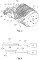
- FIG. 3 shows a device 10 according to another embodiment of the invention, in which a camera 20 in response to a signal of a position sensor 13 in a release position in or against the direction of the end face 51 of the products 50 is movable, the position sensor 13 directed to a measuring position II is.
- the camera 20 is arranged here with an electronic signal processing device 24 in a housing 104.
- the products 50 to be inspected are conveyed in a transverse conveyor 2 designed as a drum.
- the products 50 are held in troughs 103.
- the cross conveyor 2 completes a rotational movement about an axis of rotation at a defined angular velocity.
- the position sensor 13 records the position of the product 50 within the trough 103.
- the product 50 then moves in the direction of rotation in accordance with the rotational movement and passes from the measuring position II to a receiving position III, which is given by the camera 20 and, in this embodiment, a beam deflection 102.
- the beam deflector 102 may be eliminated if the optical axis of the camera 20 is aligned coaxially with the cross conveyor and thus directed towards the product 50.
- the beam deflection 102 includes, for example, prisms and / or mirrors.
- the triggering position of the camera 20 can be determined by the distance between the camera 20 and the product 50 from the position sensor 13 at the measuring position II or the position of the product 50 in the depressions 103 of the transverse conveyor 2.
- the camera 20 is held on a sliding device 100 designed as a linear slide in order to allow an adjustment of the camera 20.
- a motor 101 By means of a motor 101, the position of the camera 20 along the displacement device 100 can be moved parallel to the longitudinal axis of the products 50 in order to be able to adjust the distance between the camera 20 and an end face 51 of the product 50 to be inspected.
- the motor 101 is, for example, an electrically driven motor, preferably a stepping motor and / or a linear motor.
- a suitable sensor and / or preferably by means of the stepping motor the position of the camera 20 can be determined. Based on the known positions of product 50 and camera 20, the triggering position of the camera 20 necessary for a sharp image can be set, for example after a brand and / or format change.
- the displacement device 100 and / or the motor 101 can be dispensed with if, for example, the camera 20 has a variable focal plane which matches the focal plane of the camera 20 or the lens of the camera 20 with the distance between the camera 20 and the end surface 51 allowed.
- an operator of the device 10 performs a rough adjustment adapted to the format and a fine adjustment takes place with the means described in the embodiments.
- the operator can preferably be given feedback on the automatic adjustment.
- FIG. 4 schematically illustrates an arrangement for receiving images of the end faces 51 of products 50 with different lengths 204, 205.
- the different lengths 204, 205 of the products 50 can come about, for example, by a format change.
- the distances 201, 202 between the camera 20 and the end face 51 of the product 50 to be inspected are different.
- a longer product 50 results in a smaller distance 201 while a shorter product 50 results in a larger distance 202.
- the camera 20 may be movable according to the distances 201, 202 in a triggering position and / or have a variable focal plane.
- the variable focal plane can be adjusted so that it is always set according to the distance 201, 202 when taking a picture.
- variable focal plane can be achieved by a zoom lens in order to be able to focus and sharply image the end faces 51 at the given distances 201, 202.
- various distances 201, 202 come about not only by a format change, but also by an inaccurate positioning of the products 50 in, for example, a transverse conveyor 2, which can be compensated according to the embodiments of the invention.
Abstract
Die vorliegende Erfindung betrifft eine Vorrichtung (10) zur Inspektion einer Stirnfläche (51) eines stabförmigen Rauchartikels (5), wobei die Rauchartikel (5) auf einer Führungseinrichtung (4) in längsaxialer Anordnung zuführbar und über einen Querförderer (2) aus der längsaxialen Führungseinrichtung (4) queraxial abförderbar sind, umfassend eine Kamera (20), die zur Aufnahme von Bildern der sich in einer Aufnahmeposition (III) befindlichen Stirnfläche (51) eingerichtet ist, und eine elektronische Signalverarbeitungseinrichtung (24) zur Auswertung der von der Kamera (20) aufgenommenen Bilder. Ein auf eine Messposition (II) gerichteter Positionssensor (13) ist vorgesehen, welcher bei der Förderung der Rauchartikel (5) durch die Messposition (II) ein Signal erzeugt und an die Kamera (20) weiterleitet, und die Kamera (20) ist in Abhängigkeit von dem Signal des Positionssensors (13) auslösbar und/oder in eine Auslöseposition verfahrbar.The present invention relates to a device (10) for inspecting an end face (51) of a rod-shaped smoking article (5), wherein the smoking article (5) can be fed on a guide device (4) in a longitudinal axial arrangement and via a transverse conveyor (2) from the longitudinal axial guide device (4) are transportable transversely axially, comprising a camera (20) which is adapted to receive images of the located in a receiving position (III) end face (51), and an electronic signal processing means (24) for evaluating the from the camera (20 ) taken pictures. A position sensor (13) directed towards a measuring position (II) is provided, which generates a signal during the conveyance of the smoking articles (5) through the measuring position (II) and forwards them to the camera (20), and the camera (20) is in Dependent on the signal of the position sensor (13) triggered and / or moved to a release position.
Description
Die vorliegende Erfindung betrifft eine Vorrichtung zur Inspektion einer Stirnfläche eines stabförmigen Rauchartikels mit den Merkmalen des Oberbegriffs von Anspruch 1 und ein Verfahren zur Inspektion einer Stirnfläche eines stabförmigen Rauchartikels mit den Merkmalen des Oberbegriffs von Anspruch 10.The present invention relates to a device for inspecting an end face of a rod-shaped smoking article having the features of the preamble of
Stabförmige Rauchartikel sind z.B. Zigaretten, Zigarillos, Heat Not Burn-Produkte (HNB-Produkte) oder ähnliche Produkte, welche zur Inhalation eines Konsumenten vorgesehen sind. Dabei können trotz des Begriffs nicht nur Rauch sondern stattdessen oder zusätzlich auch ätherische oder medizinische Substanzen zur Inhalation vorgesehen sein. Als stabförmige Rauchartikel sind dabei auch Vorprodukte von Rauchartikeln zu verstehen wie z.B. Filterstäbe, Tabakstöcke mit einem durch einen Umhüllungsstreifen formstabilisierten Tabakmaterial, Segmente von HNB-Produkte, wie rohrförmige Kühlabschnitte, geschmacksbeeinflussende Segmente oder dergleichen anzusehen, welche nachfolgend mit anderen Vorprodukten zu einem fertigen stabförmigen Rauchartikel verbunden werden.Rod shaped smoking articles are e.g. Cigarettes, cigarillos, Heat Not Burn products (HNB products) or similar products intended for the inhalation of a consumer. In this case, despite the term, not only smoke but instead or additionally also ethereal or medicinal substances for inhalation may be provided. As rod-shaped smoking articles are also precursors of smoking articles to understand such. Filter rods, tobacco sticks with a by a strip strip shape-stabilized tobacco material, segments of HNB products, such as tubular cooling sections, taste-affecting segments or the like to see, which are subsequently connected to other precursors to a finished rod-shaped smoking article.
Die stabförmigen Rauchartikel und Vorprodukte der Rauchartikel werden nachfolgend in der Beschreibung zur Vereinfachung als Produkte bezeichnet.The rod-shaped smoking articles and precursors of the smoking articles are referred to hereinafter as "products" in the description for the sake of simplicity.
Zur Förderung von Produkten wird eine Fördereinrichtung verwendet, welche einen Formatabschnitt umfasst, in dem ein endloser Strang eines Materials, wie zum Beispiel eines Tabaks oder Tows, auf eine endlose Bahn eines Hüllenmaterials aufgelegt wird, welcher dann durch Umlegen und Verkleben der Randseiten des Hüllenmaterials zu einem festen Strang fixiert wird. Dieser formfeste Strang wird anschließend mittels eines rotierenden Messerträgers mit mehreren radial außen abrangenden Messern in zylindrische beziehungsweise stabförmige Produkte mit einer vorbestimmten Stablänge geschnitten. Nach dem Schneiden werden die Produkte auf einer Führungseinrichtung als Strang von aneinander anliegenden Einzelprodukten in einer längsaxialen Transportrichtung beziehungsweise Strangrichtung zu einem Übernahmepunkt weitergeschoben oder alternativ auch aktiv weitertransportiert. In dem Übernahmepunkt werden die Produkte mit einem Längsförderer von der Führungseinrichtung abgefördert und zu einem Übergabepunkt transportiert, in dem die Produkte von dem Längsförderer quer zu ihrer Längsrichtung an einen Querförderer übergeben werden. Der formfeste Strang oder der Strang von aneinander anliegenden Einzelprodukten kann auch ohne Umhüllungspapier vorliegen, beispielsweise zur Förderung und Anwendung von Non-wrapped-acetat-Filtern (NWA-Filtern).To convey products, a conveyor is used which comprises a format section in which an endless strand of material, such as a tobacco or tow, is placed on an endless web of casing material, which is then folded over and adhered to the edge sides of the casing material is fixed to a solid strand. This dimensionally stable strand is subsequently cut into cylindrical or rod-shaped products having a predetermined rod length by means of a rotating knife carrier with a plurality of radially outwardly projecting knives. After cutting, the products are pushed on a guide device as a strand of adjoining individual products in a longitudinal axial transport direction or strand direction to a takeover point or alternatively also actively transported. In the takeover point, the products are conveyed away with a longitudinal conveyor of the guide device and transported to a transfer point, in which the products are transferred from the longitudinal conveyor transversely to its longitudinal direction to a cross conveyor. The dimensionally stable strand or the strand of adjoining individual products can also be present without wrapping paper, for example for the conveying and application of non-wrapped acetate filters (NWA filters).
Der Längsförderer ist durch eine rotatorisch angetriebene Trommel gebildet, welche eine Mehrzahl von vorstehenden, drehbar gelagerten Hebelarmen aufweist. An jedem der Hebelarme sind ein oder mehrere axial beabstandete Aufnahmen vorgesehen, an denen ein oder mehrere parallel zu den zugeführten Produkten ausgerichtete, mit Unterdruck beaufschlagbare Rinnen beziehungsweise Mulden vorgesehen sind. Die Hebelarme führen während des Umlaufs der Trommel für einen außenstehenden Betrachter eine zu der Drehbewegung der Trommel gegensinnige Drehbewegung aus, so dass die Aufnahmen auf einer elliptischen Bewegungsbahn geführt werden. Die Aufnahmen selbst werden während der Umlaufbewegung der Trommel und der Hebelarme mittels einer Mechanik in einer konstanten, vorzugsweise horizontalen Ausrichtung gehalten, was eine Ausrichtung der in den Aufnahmen gehaltenen Produkte gewährleistet, wobei die Längsachsen der Produkte stets vorzugsweise parallel zur Transportrichtung des zugeführten Stranges sind. Während des Umlaufens der Trommel werden die Aufnahmen mit den daran vorgesehenen Rinnen in einem Übernahmepunkt so dicht an den Produkten vorbeigeführt, dass die Produkte durch den in den Rinnen wirkenden Unterdruck angesaugt und von der Fördereinrichtung abgefördert werden. Während der weiteren Transportbewegung werden die Produkte zu einem Übergabepunkt bewegt, in dem die Rinnen mit den darin gehaltenen Produkten eine vorzugsweise reine Querbewegung zu ihren Längsachsen beziehungsweise zu der Transportrichtung der Führungseinrichtung ausführen. Ferner ist ein Querförderer vorgesehen, welcher ebenfalls durch eine rotatorisch antreibbare Trommel gebildet ist, aber mit seiner Drehachse in einer vorzugsweise rechtwinkligen Anordnung zu der Drehachse des Längsförderers angeordnet ist. An der radial äußeren Mantelfläche des Querförderers sind eine Mehrzahl von ebenfalls mit Unterdruck beaufschlagbarer und parallel zu der Drehachse des Querförderers ausgerichteter Rinnen vorgesehen, welche in dem Übergabepunkt so dicht an den Rinnen des Längsförderers und den darin gehaltenen Produkten vorbeigeführt werden, dass die Produkte quer zu ihrer Längsachse übernommen und weitertransportiert werden.The longitudinal conveyor is formed by a rotationally driven drum, which has a plurality of protruding, rotatably mounted lever arms. On each of the lever arms, one or more axially spaced receptacles are provided, to which one or more aligned parallel to the supplied products, can be acted upon with negative pressure channels or troughs. The lever arms perform during the circulation of the drum for an outside observer to an opposite rotational movement of the drum rotational movement, so that the recordings are guided on an elliptical trajectory. The recordings themselves are held during the orbital movement of the drum and the lever arms by means of a mechanism in a constant, preferably horizontal orientation, which is a Ensures alignment of the products held in the recordings, wherein the longitudinal axes of the products are always preferably parallel to the transport direction of the supplied strand. During the rotation of the drum, the receptacles with the grooves provided thereon are guided past the products in a transfer point so close to the products that the products are sucked in by the negative pressure acting in the grooves and removed by the conveyor. During the further transport movement, the products are moved to a transfer point, in which the channels with the products held therein perform a preferably purely transverse movement relative to their longitudinal axes or to the transport direction of the guide device. Further, a transverse conveyor is provided, which is also formed by a rotatably drivable drum, but is arranged with its axis of rotation in a preferably rectangular arrangement to the axis of rotation of the longitudinal conveyor. On the radially outer circumferential surface of the transverse conveyor a plurality of likewise be acted upon by negative pressure and aligned parallel to the axis of rotation of the transverse conveyor grooves are provided, which are passed in the transfer point so close to the grooves of the longitudinal conveyor and the products held therein, that the products across taken over their longitudinal axis and further transported.
Ein Problem bei dem Transport der Produkte ist, dass die Rinnen der Aufnahmen des Längsförderers in dem Übernahmepunkt mit einer höheren Geschwindigkeit als die Geschwindigkeit der zugeführten Produkte (auch Übergeschwindigkeit genannt) bewegt werden müssen, damit die dem Längsförderer auf der Führungseinrichtung zugeführten Produkte auf keinen Fall aufstauen oder während der Übernahmebewegung mit dem nachfolgenden Produkt kollidieren können. Die Übergeschwindigkeit ist dabei außerdem abhängig von der Stablänge der Produkte, da die Drehzahl des Längsförderers der Fördereinrichtungen auch für den Transport von Produkten unterschiedlicher Stablänge gleich ist, und die Stranggeschwindigkeit der zugeführten Produkte auf eine vorbestimmte Anzahl von zu übernehmenden Produkten je Zeiteinheit abgestimmt werden muss. Die Produkte werden aus diesen Gründen unter ungünstigen Umständen mit einer bis zu zweifachen Übergeschwindigkeit im Vergleich zu der Zuführgeschwindigkeit der Produkte übernommen. Die Rinnen selbst weisen ferner eine bestimmte Oberflächenrauheit auf, welche die wirkenden Reibkräfte zwischen den Rinnen und den Produkten bei der Übernahme mitbestimmt.A problem with the transport of the products is that the grooves of the longitudinal conveyor receivers have to be moved at the takeover point at a speed higher than the speed of the supplied products (also called overspeed) so that the products fed to the longitudinal conveyor on the guide means will not damming or colliding with the subsequent product during the takeover. The overspeed is also dependent on the rod length of the products, since the speed of the longitudinal conveyor of the conveyors is the same for the transport of products of different rod length, and the strand speed of the supplied products must be matched to a predetermined number of products to be accepted per unit time. For these reasons, the products are taken under unfavorable conditions at up to twice the overspeed compared to the feed rate of the products. The grooves themselves also have a certain surface roughness, which determines the effective frictional forces between the grooves and the products in the acquisition.
Aufgrund dieser Übergeschwindigkeit werden die Produkte bei der Übernahme ruckartig beschleunigt, wodurch auf die Produkte bestimmte Kräfte in Axial- und Radialrichtung wirken, welche unter anderem für den Kopfausfall der Produkte ursächlich sind. Die Übergeschwindigkeit sollte daher grundsätzlich möglichst gering bzw. nur um einen geringfügigen Betrag höher als die Zuführgeschwindigkeit der Produkte sein. Außerdem ist es nicht zu vermeiden, dass die Stäbe mit einem Schlupf übernommen werden, was z.B. an einer zu hohen Übergeschwindigkeit oder an einer Verminderung der Oberflächenrauheit der Rinnen nach einer längeren Betriebszeit liegen kann. Dieser Schlupf kann eine Abweichung der relativen Ist-Lage der Produkte in Längsrichtung der Rinnen des Längsförderers von der vorgegebenen Soll-Lage zur Folge haben, welche zwangsläufig auch eine Abweichung der Ist-Lage der Produkte in Längsrichtung der Rinnen des Querförderers von einer vorgegebenen Soll-Lage zur Folge hat. Da die Produkte von dem Querförderer ausschließlich quer zu ihren Längsachsen transportiert werden, bleibt diese Abweichung auch während des weiteren Transportweges erhalten, sofern diese nicht z.B. mittels einer seitlichen Anlagescheibe weggetaumelt wird. Die Ausrichtung der Produkte in den Rinnen des Querförderers ist insbesondere dann von besonders großer Bedeutung, wenn die Produkte in doppelter Länge transportiert werden und in dieser Stellung auf dem Querförderer in Produkte einfacher Länge geschnitten werden, da die Lage der Produkte in den Rinnen des Querförderers bei einer feststehenden Schnittkante auch anschließend die Längen der geschnittenen, einfach langen Produkte entscheidend mit beeinflusst.Due to this overspeed, the products are accelerated in the takeover jerky, which act on the products certain forces in the axial and radial directions, which are among other things responsible for the head failure of the products. The overspeed should therefore be as low as possible or only a small amount higher than the feed rate of the products. In addition, it is inevitable that the rods are taken over with a slippage, which may be due to excessive overspeeding or a reduction in the surface roughness of the grooves after a longer period of operation. This slippage can result in a deviation of the relative actual position of the products in the longitudinal direction of the grooves of the longitudinal conveyor from the predetermined desired position, which inevitably also results in a deviation of the actual position of the products in the longitudinal direction of the grooves of the transverse conveyor from a predetermined target position. Situation has. Since the products are transported by the cross conveyor exclusively transverse to their longitudinal axes, this deviation is maintained during the further transport path, unless this example by means of a lateral Investment disc is staggered away. The orientation of the products in the grooves of the cross conveyor is especially of great importance when the products are transported in double length and cut in this position on the cross conveyor in products of simple length, since the location of the products in the gutters of the cross conveyor at a fixed cutting edge then also influenced the lengths of the cut, simply long products decisively.
Für die Qualitätsüberwachung bei der Herstellung der Produkte, beispielsweise bei der Filter-/Zigarettenherstellung, ist beispielsweise in Filterherstellmaschinen ein auf bildgebende Sensorik basierender Stirnflächensensor vorgesehen. Die Produkte werden typischerweise einer optischen Prüfung mittels einer Kamera, die zur Aufnahme von Bildern einer Stirnfläche der Produkte eingerichtet ist, unterzogen. Die von der Kamera aufgenommenen Bilder werden anschließend durch eine elektronische Signalverarbeitungseinrichtung ausgewertet.For quality monitoring during the production of the products, for example in the filter / cigarette production, a sensor based on imaging sensor face sensor is provided, for example, in filter manufacturing. The products are typically subjected to optical inspection by means of a camera adapted to receive images of an end face of the products. The images taken by the camera are then evaluated by an electronic signal processing device.
Eine Messvorrichtung für die On-line Messung ist beispielsweise aus der
Die Abweichung der Ist-Lage von der Soll-Lage der Produkte in dem Querförderer von bis zu ± 5 mm impliziert jedoch eine Unschärfe der aufgenommenen Bilder durch die von der Fokusebene der Kamera abweichende und ungenaue Positionierung der Produkte innerhalb der Mulden des Querförderers, was eine zuverlässige Inspektion der Stirnfläche auf der Trommel erschwert.The deviation of the actual position from the desired position of the products in the transverse conveyor of up to ± 5 mm, however, implies a blurring of the recorded images due to the inaccurate positioning of the products within the troughs of the transverse conveyor, which differs from the focal plane of the camera Reliable inspection of the face on the drum difficult.
Eine mögliche Ausrichtung der Produkte innerhalb der Mulden der Trommel in axialer Richtung findet typischerweise zur Mitte der Abgabetrommel statt. Dies führt dazu, dass sich der Abstand zwischen der Stirnfläche eines Produktes und der Kamera bei einer Längenänderung der Produkte beziehungsweise einem Formatwechsel verändert. Dadurch ist nach der Längenänderung beziehungsweise dem Formatwechsel der Abstand zwischen der Kamera und der zu inspizierenden Stirnfläche ein anderer als vor der Längenänderung beziehungsweise dem Formatwechsel, und eine gültige Messung mit der Kamera ist nicht möglich. Gemäß dem Stand der Technik muss die Kamera bisher nach jedem Formatwechsel erneut justiert werden.Possible alignment of the products within the wells of the drum in the axial direction typically occurs towards the center of the dispensing drum. As a result, the distance between the end face of a product and the camera changes with a change in length of the products or a format change. As a result, after the change in length or the format change, the distance between the camera and the end face to be inspected is different from before the change in length or the format change, and a valid measurement with the camera is not possible. According to the prior art, the camera has to be readjusted after each format change.
Eine ungenaue Justage führt zu einem unscharfen Bild. Ferner muss der Abbildungsmaßstab eingehalten werden, um eine korrekte Bildauswertung in der elektronischen Signalverarbeitungseinrichtung sicherzustellen. Ein Fehler der Justage der Kamera beziehungsweise im Abstand zwischen Kamera und zu inspizierender Stirnfläche stellt daher eine Fehlerquelle dar, die nicht beziehungsweise nur schwer anhand der Messdaten erkannt werden kann. Somit besteht die Gefahr, dass die Messwerte der Kamera nicht korrekt sind, dies jedoch nicht bemerkt wird. Die oben beschriebene Abweichung zwischen der Ist-Lage und der Soll-Lage der Produkte in dem Querförderer stellt eine zusätzliche, nicht durch eine Justage zu behebende Abweichung dar. Dies kann dazu führen, dass Produkte mit verminderter Qualität nicht ordnungsgemäß erkannt werden.An inaccurate adjustment leads to a blurred image. Furthermore, the magnification must be maintained in order to ensure correct image evaluation in the electronic signal processing device. An error in the adjustment of the camera or in the distance between the camera and the face to be inspected therefore represents a source of error which can not or only with difficulty be detected on the basis of the measurement data. Thus, there is a risk that the measured values of the camera are not correct, but this is not noticed. The above-described deviation between the actual position and the desired position of the products in the cross conveyor represents an additional deviation that can not be corrected by an adjustment. This can lead to products with reduced quality not being recognized correctly.
Eine Aufgabe der Erfindung ist es, eine Vorrichtung und ein entsprechendes Verfahren bereitzustellen, welche eine effektive und zuverlässige Qualitätssicherung durch eine zuverlässige optische Prüfung der Produkte ermöglichen.An object of the invention is to provide an apparatus and a corresponding method which provide an effective and Ensure reliable quality assurance through reliable optical testing of the products.
Zur Lösung der Aufgabe werden erfindungsgemäß eine Vorrichtung mit den Merkmalen von Anspruch 1 und ein Verfahren mit den Merkmalen von Anspruch 10 vorgeschlagen. Weitere bevorzugte Weiterentwicklungen der Erfindung sind den Unteransprüchen, den Figuren und der zugehörigen Beschreibung zu entnehmen.To achieve the object, a device with the features of
Erfindungsgemäß wird vorgeschlagen, dass ein auf eine Messposition gerichteter Positionssensor vorgesehen ist, welcher bei der Förderung der Rauchartikel durch die Messposition ein Signal erzeugt und an die Kamera weiterleitet, und die Kamera in Abhängigkeit von dem Signal des Positionssensors auslösbar und/oder in eine Auslöseposition verfahrbar ist.According to the invention, it is proposed that a position sensor directed at a measuring position is provided, which generates a signal when conveying the smoking article through the measuring position and forwards it to the camera, and the camera can be triggered in response to the signal of the position sensor and / or moved into a triggering position is.
Die Erfindung hat erkannt, dass der Abstand zwischen der Kamera und dem Rauchartikel einen festgelegten Wert einhalten muss, um mit der Kamera eine für die Auswertung ausreichend scharfe Abbildung zu generieren. Das Auslösen der Kamera in Abhängigkeit von dem Signal des Positionssensors gewährleistet, dass die Kamera Bilder nur unter der Bedingung aufnimmt, wenn sich der Rauchartikel in einer definierten Position befindet, die zum Zeitpunkt der Sensierung durch den Positionssensor der Messposition entspricht. Das Signal, welches anzeigt, dass sich der Rauchartikel in der Messposition befindet, wird sodann an die Kamera weitergeleitet, um eine Aufnahme auszulösen und/oder eine für eine Aufnahme günstige Bedingung hervorzurufen, bei der eine scharfe Abbildung gemacht werden kann. Das Sensieren kann auf unterschiedliche Arten realisiert sein, z.B. indem direkt auf den Rauchartikel und/oder auf ein mit der Position des Rauchartikels gekoppeltes Maschinenteil referenziert wird. Durch die definierte Position des Rauchartikels kann die Kamera so angeordnet sein und/oder in die Auslöseposition verfahrbar sein, dass die Entfernung zwischen Kamera und dem Rauchartikel dem festgelegten Abstand entspricht, um ein scharfes Bild mit der Kamera aufzeichnen zu können. Das Verfahren in die Auslöseposition dient dem exakten Einstellen des Abstandes und gewährleistet eine scharfe Abbildung der Stirnfläche. Eine Schwankung der Position des Rauchartikels, beispielsweise bei der Übernahme, kann somit bei der Aufnahme des Bildes berücksichtigt werden. Auch eine Variation der Länge der Rauchartikel kann somit ohne weiteren Aufwand kompensiert werden. Eine im Stand der Technik sonst übliche manuelle Justage der Auslöseposition auf die entsprechende Länge des Rauchartikels ist somit nicht notwendig, d.h. die Vorrichtung und das entsprechende Verfahren gemäß der Erfindung arbeiten formatunabhängig. Die Aufnahme eines Bildes durch die Kamera kann so erfolgen, dass die Kamera auf Grundlage des erzeugten Signals die Belichtung über eine bestimmte Belichtungszeit, beispielsweise im Bereich von Sekundenbruchteilen, gewährleistet und während der Belichtung ein Beleuchtungsmittel die zu inspizierende Stirnfläche beleuchtet. Wahlweise kann das Beleuchtungsmittel eine LED umfassen. Die Beleuchtungsdauer kann vorzugsweise kleiner als die Belichtungszeit sein.The invention has recognized that the distance between the camera and the smoking article must comply with a specified value in order to generate a sufficiently sharp image with the camera for the evaluation. Triggering the camera in response to the position sensor signal ensures that the camera will only take pictures under the condition that the smoking article is in a defined position that corresponds to the measuring position at the time the position sensor senses it. The signal indicating that the smoking article is in the measurement position is then forwarded to the camera to initiate a capture and / or to provide a condition favorable to capture, where a sharp image can be taken. The sensing can be realized in different ways, eg by referencing directly to the smoking article and / or to a machine part coupled to the position of the smoking article becomes. Due to the defined position of the smoking article, the camera can be arranged and / or moved to the release position such that the distance between the camera and the smoking article corresponds to the specified distance in order to be able to record a clear image with the camera. The procedure in the release position is used for the exact adjustment of the distance and ensures a sharp image of the end face. A fluctuation of the position of the article, for example, during the acquisition, can thus be taken into account when taking the picture. Also, a variation of the length of the smoking article can thus be compensated without further effort. A customary in the prior art manual adjustment of the triggering position on the corresponding length of the smoking article is therefore not necessary, ie the device and the corresponding method according to the invention work independently of format. The acquisition of an image by the camera can be carried out so that the camera on the basis of the generated signal, the exposure over a certain exposure time, for example in the range of fractions of seconds, guaranteed, and during the illumination, a lighting illuminates the inspected end face. Optionally, the illumination means may comprise an LED. The illumination duration may preferably be smaller than the exposure time.
Vorzugsweise löst die Kamera gleichzeitig zum Eingang des Signals eine Aufnahme eines Bildes des von dem Positionssensor detektierten Rauchartikels aus, um im Falle eines dem für eine scharfe Abbildung festgelegten Wert entsprechenden Abstandes zwischen Kamera und Rauchartikel ein scharfes Bild von dem jeweils am Positionssensor vorbei geführten Rauchartikel mit der Kamera aufzeichnen zu können. In dieser Ausführungsform passiert der Rauchartikel zum Zeitpunkt der Erzeugung des Signals die Fokusebene des Objektivs der Kamera, d.h. die Messposition liegt in der Fokusebene der Kamera beziehungsweise die Auslöseposition ist von der Messposition um einen zur Fokusebene entsprechenden Wert beabstandet. Ein gleichzeitiges Auslösen einer Aufnahme bewirkt somit ein scharfes Bild des sensierten beziehungsweise detektierten Rauchartikels. Unter dem gleichzeitigen Auslösen sind auch signaltechnisch bedingte Zeitdifferenzen zu verstehen, welche sich beispielsweise durch die Signalleitung von dem Positionssensor zur Kamera oder durch die Signalverarbeitung in dem Positionssensor und/oder der Kamera ergeben können und beispielsweise im Bereich von wenigen Mikrosekunden liegen können.Preferably, the camera triggers at the same time to the input of the signal recording of an image of the detected by the position sensor smoking article, in the case of the fixed distance for a sharp image corresponding distance between the camera and smoking article with a sharp image of each passed on the position sensor smoking article with to record the camera. In this embodiment, at the time of generation of the signal, the smoking article passes through the focal plane of the objective the camera, ie the measuring position is in the focal plane of the camera or the triggering position is spaced from the measuring position by a value corresponding to the focal plane. A simultaneous triggering of a recording thus causes a sharp image of the sensed or detected smoking article. Under the simultaneous trigger signal-related time differences are to be understood, which may result, for example, by the signal line from the position sensor to the camera or by the signal processing in the position sensor and / or the camera and may for example be in the range of a few microseconds.
In einer bevorzugten Ausführungsform ermittelt die elektronische Signalverarbeitungseinrichtung in Abhängigkeit von dem Signal des Positionssensors und der Zeitspanne, welche der Rauchartikel zur Bewegung aus der Messposition in die Aufnahmeposition benötigt, einen Auslösezeitpunkt der Kamera zum Auslösen eines Bildes, beispielsweise um die Anordnung des Positionssensors und der Kamera unter Ausnutzung der Bewegung des Rauchartikels und/oder der Fördereinrichtung örtlich voneinander entkoppeln zu können. In dieser Ausführungsform passiert der Rauchartikel beispielsweise aufgrund der Bewegung der Fördereinrichtung nach dem Zeitpunkt der Erzeugung des Signals mit einem Zeitversatz die Fokusebene. Somit kann die Kamera auf eine von der Messposition verschiedene Aufnahmeposition gerichtet sein, die zu einem definierten Zeitpunkt von dem Rauchartikel passiert wird, was eine an die konstruktiven Umstände anpassungsfähige Anordnung der Kamera ermöglicht. Der Auslösezeitpunkt wird so ermittelt, dass sich genau der von dem Positionssensor detektierte Rauchartikel zum Auslösezeitpunkt durch die Aufnahmeposition bewegt, um definierte und produktbezogene Aufnahmen machen zu können.In a preferred embodiment, the electronic signal processing device determines a triggering time of the camera for triggering an image, for example the arrangement of the position sensor and the camera, in dependence on the signal of the position sensor and the time required for the smoking article to move from the measuring position to the receiving position be able to decouple locally from each other by utilizing the movement of the smoking article and / or the conveyor. In this embodiment, for example, due to the movement of the conveyor after the time of generation of the signal with a time offset, the smoking article passes through the focal plane. Thus, the camera can be directed to a different picking position from the measuring position, which is passed by the smoking article at a defined time, which allows an adaptable to the structural circumstances arrangement of the camera. The triggering time is determined in such a way that exactly the smoke article detected by the position sensor moves through the pickup position at the time of triggering in order to be able to make defined and product-related shots.
Bevorzugt wird der Auslösezeitpunkt in Abhängigkeit von der Bewegung des Querförderers bestimmt, um eine definierte Winkelgeschwindigkeit beziehungsweise Drehzahl des vorzugsweise als Trommel ausgeführten Querförderers für eine exakte Prognose der Bewegung der Rauchartikel im Querförderer zu nutzen und so die Bewegung der Rauchartikel durch die Aufnahmeposition zu bestimmen. In dieser Ausführungsform ist die optische Achse der Kamera vorzugsweise parallel zu der Drehachse des Querförderers und mithin parallel zu den Längsachsen der im Querförderer geförderten Rauchartikel.Preferably, the triggering time is determined as a function of the movement of the cross conveyor in order to use a defined angular velocity or rotational speed of the transverse conveyor preferably designed as a drum for an accurate prediction of the movement of the smoking article in the cross conveyor and thus to determine the movement of the smoking article through the receiving position. In this embodiment, the optical axis of the camera is preferably parallel to the axis of rotation of the cross conveyor and thus parallel to the longitudinal axes of the conveyed in the cross conveyor smoking article.
Vorteilhaft wird der Auslösezeitpunkt in Abhängigkeit von der Bewegung des Rauchartikels in einer Transportrichtung des Rauchartikels bestimmt. Die Transportrichtung des Rauchartikels ist in der Führungseinrichtung gleich der Längsachse der als Strang geförderten Rauchartikel. Bevorzugt wird der Auslösezeitpunkt in Abhängigkeit von der Transportrichtung des Rauchartikels in der Führungseinrichtung beziehungsweise parallel dazu ermittelt, da damit die Bewegung des Rauchartikels in oder entgegen der Richtung der Kamera genutzt wird, welche die relevante Richtung für die scharfe Abbildung der Stirnfläche ist. In dem Querförderer ist die Transportrichtung der Rauchartikel senkrecht zu deren Längsachsen und aus der Transportrichtung und der Position der Rauchartikel lässt sich exakt bestimmen, wann die jeweiligen Produkte die Aufnahmeposition durchqueren.Advantageously, the triggering time is determined as a function of the movement of the smoking article in a direction of transport of the smoking article. The transport direction of the article is in the guide means equal to the longitudinal axis of the promoted as a strand smoking article. Preferably, the triggering time is determined as a function of the transport direction of the smoking article in the guide device or parallel thereto, since it uses the movement of the smoking article in or against the direction of the camera, which is the relevant direction for the sharp imaging of the end face. In the transverse conveyor, the transport direction of the smoking articles is perpendicular to their longitudinal axes and out of the transport direction, and the position of the smoking articles can be accurately determined when the respective products pass through the receiving position.
Vorzugsweise ist der Positionssensor derart angeordnet, dass er die Position eines Rauchartikels detektiert, welcher von einem zwischen der Führungseinrichtung und dem Querförderer angeordneten, zu einer Rotationsbewegung antreibbaren Längsförderer transportiert wird, um eine Aufnahme des Rauchartikels machen zu können, nachdem der Rauchartikel an einem Übernahmepunkt von der Führungseinrichtung vom Längsförderer übernommen wurde. Der Längsförderer fördert die Rauchartikel in und/oder parallel zu der Transportrichtung beziehungsweise in längsaxialer Richtung der Rauchartikel. Somit kann vorzugsweise die Bewegung des Längsförderers für die Ermittlung des Auslösezeitpunkt genutzt werden. In dieser Ausführungsform wird ein produktbezogenes Bild von dem mit dem Positionssensor sensierten Rauchartikel gemacht, nachdem es durch die Übergeschwindigkeit eine ungenaue Position in den das Rauchartikel haltenden Rinnen des Längsförderers einnimmt. Die Fehlerquelle der Übernahme der Rauchartikel liegt damit in Bezug auf die Transportrichtung stromaufwärts zu der Messposition, so dass dieser Fehler bereits in der detektierten Position des Rauchartikels enthalten ist und ausgeglichen werden kann. In dieser Ausführungsform kann vor der Übergabe an den Querförderer eine Qualitätsprüfung an einer definierten Position durchgeführt werden. Beispielsweise kann so die Transportgeschwindigkeit des Längsförderers in Transportrichtung in die Bestimmung des Auslösezeitpunktes einbezogen werden.Preferably, the position sensor is arranged such that it detects the position of a smoking article, which is transported by a arranged between the guide means and the cross conveyor, can be driven to a rotational movement longitudinal conveyor to take a picture of the smoking article, after the smoking article has been taken over at a takeover point by the guide device from the longitudinal conveyor. The longitudinal conveyor conveys the smoking articles in and / or parallel to the transport direction or in the longitudinal axial direction of the smoking article. Thus, preferably, the movement of the longitudinal conveyor can be used for the determination of the triggering time. In this embodiment, a product-related image is taken of the smoking article sensed by the position sensor after it has an inaccurate position in the smoking article retaining grooves of the longitudinal conveyor due to the overspeed. The source of error of the adoption of the smoking article is thus with respect to the transport direction upstream of the measuring position, so that this error is already included in the detected position of the smoking article and can be compensated. In this embodiment, a quality inspection at a defined position can be carried out before the transfer to the cross conveyor. For example, the transport speed of the longitudinal conveyor in the transport direction can thus be included in the determination of the triggering time.
Vorzugsweise wird der Auslösezeitpunkt in Abhängigkeit von der Rotationsbewegung des Längsförderers bestimmt. In dieser Ausführungsform ist der Längsförderer vorzugsweise als Trommel ausgeführt und führt eine Rotationsbewegung um eine Rotationsachse durch. Durch die Rotation mit vorzugsweise konstanter Winkelgeschwindigkeit wird der Rauchartikel mit einer bestimmbaren Geschwindigkeit gefördert und die Position zur Aufnahme zum Aufnahmezeitpunkt ist ausgehend von der Messposition exakt bestimmbar.Preferably, the triggering time is determined in dependence on the rotational movement of the longitudinal conveyor. In this embodiment, the longitudinal conveyor is preferably designed as a drum and performs a rotational movement about an axis of rotation. By the rotation with preferably constant angular velocity of the smoking article is promoted with a determinable speed and the position for recording at the time of recording is determined exactly from the measuring position.
Vorzugsweise wird der Auslösezeitpunkt unter Berücksichtigung eines sich aus der Messposition und der Aufnahmeposition ergebenden Drehwinkels des Längsförderers bestimmt, um eine definierte Position für die Qualitätsprüfung anhand der Dynamik des Längsförderers auf besonders einfache und exakte Art bestimmbar zu machen. Die Rotation des Längsförderers um einen Winkel führt zu einer Bewegung quer zur Transportrichtung beziehungsweise zur Längsachse des Rauchartikels und erlaubt die Anordnung der Kamera, so dass deren optische Achse nicht auf die Führungsbahn gerichtet sein muss. Die Kamera kann an die konstruktiven Gegebenheiten anpassbar und mit ihrer optischen Achse parallel zur Transportrichtung der Führungsbahn angeordnet sein. Dabei wird der Auslösezeitpunkt so bestimmt, dass zum Zeitpunkt der Aufnahme des Messsignals durch den Positionssensor die Zeit hinzuaddiert wird, welche notwendig ist, um den von dem Längsförderer transportierten, detektierten Rauchartikel aus der Messposition in die Aufnahmeposition zur Aufnahme des Bildes durch die Kamera zu bewegen.Preferably, the triggering time is determined taking into account a resulting from the measuring position and the receiving position rotation angle of the longitudinal conveyor to make a defined position for the quality inspection based on the dynamics of the longitudinal conveyor in a particularly simple and accurate manner. The rotation of the longitudinal conveyor by an angle leads to a movement transversely to the transport direction or to the longitudinal axis of the smoking article and allows the arrangement of the camera, so that the optical axis does not have to be directed to the guideway. The camera can be adapted to the structural conditions and arranged with its optical axis parallel to the transport direction of the guideway. In this case, the triggering time is determined such that, at the time the measurement signal is received by the position sensor, the time necessary to move the detected smoking article transported by the longitudinal conveyor from the measuring position to the receiving position to take the image through the camera is added thereto ,
Bevorzugt ist der Positionssensor dazu eingerichtet, beim Passieren der zu inspizierenden Stirnfläche das Signal zu erzeugen, um das Signal direkt an die Position der zu inspizierenden Stirnfläche zu koppeln und von dieser scharfe Bilder mit der Kamera aufnehmen zu können.The position sensor is preferably set up to generate the signal when passing the end face to be inspected, in order to be able to couple the signal directly to the position of the end face to be inspected and to be able to record sharp images with the camera.
In einer vorteilhaften Ausführungsform weist die Kamera eine Fokusebene auf und ist so auslösbar und/oder verfahrbar, dass sich die zu inspizierende Stirnfläche in der Fokusebene befindet beziehungsweise die Fokusebene zur Aufnahme eines Bildes zu einem definierten Zeitpunkt durchquert. Somit ist die Fokusebene eine Soll-Ebene, in der sich die Stirnfläche des Produktes befinden soll, um ein scharfes Bild der Stirnfläche aufnehmen zu können. Mit der von dem Positionssensor gemessenen Position kann die Laufzeit berechnet werden, die verstreicht bis die Stirnfläche die Fokusebene durchquert und bei dem Durchqueren der Fokusebene kann das Bild der Stirnfläche aufgenommen werden.In an advantageous embodiment, the camera has a focal plane and can be triggered and / or moved such that the end face to be inspected is located in the focal plane or traverses the focal plane for capturing an image at a defined point in time. Thus, the focal plane is a desired plane in which the end face of the product should be located, to take a sharp picture of the face. With the position measured by the position sensor, it is possible to calculate the transit time which passes until the end face passes through the focal plane and, when crossing the focal plane, the image of the end face can be recorded.
Vorteilhaft ist die Kamera mittels einer Verschiebeeinrichtung in, oder entgegen der Richtung der Stirnfläche verfahrbar ist, um den Abstand zwischen der Kamera und der Stirnfläche, d.h. zwischen der Auslöseposition und der Aufnahmeposition einstellen zu können. Beispielsweise ist die Verschieberichtung der Kamera parallel zu der Drehachse des Querförderers, zu der Strangrichtung der Rauchartikel in der Führungseinrichtung und/oder senkrecht zur Rotationsachse des Längsförderers ausgerichtet.Advantageously, the camera is movable by means of a displacement device in, or opposite to the direction of the end face, in order to reduce the distance between the camera and the end face, i. to be able to adjust between the release position and the pickup position. For example, the displacement direction of the camera is parallel to the axis of rotation of the cross conveyor, aligned with the strand direction of the smoking article in the guide device and / or perpendicular to the axis of rotation of the longitudinal conveyor.
Vorzugsweise ist die Kamera auf eine Fokusebene einstellbar, um ein scharfes Bild aufnehmen zu können. In dieser Ausführungsform weist die Kamera vorzugsweise ein Zoomobjekt und/oder Autofokus auf. In dieser Ausführungsform weist die Kamera eine variable Fokusebene auf und die Fokusebene ist durch die Einstellung der Kamera an die ermittelte Position des Rauchartikels in der Aufnahmeposition anpassbar.Preferably, the camera is adjustable to a focal plane in order to record a sharp image can. In this embodiment, the camera preferably has a zoom object and / or autofocus. In this embodiment, the camera has a variable focal plane and the focal plane is adaptable by the adjustment of the camera to the determined position of the smoking article in the recording position.
Vorteilhaft ist der Positionssensor ein optischer Wegsensor, um den Abstand zwischen Positionssensor und Rauchartikel ermitteln zu können.Advantageously, the position sensor is an optical displacement sensor in order to be able to determine the distance between the position sensor and the smoking article.
Bevorzugt umfasst der Positionssensor eine Lichtschranke, und der Positionssensor ist vorzugsweise dazu eingerichtet, einen Lichtstrahl senkrecht zu den Längsachsen der Rauchartikel zu sensieren, um das Passieren des Rauchartikels beziehungsweise der Stirnfläche effektiv und einfach sensieren zu können. In dieser Ausführungsform wird das Signal bei der Detektion eines Rauchartikels dadurch erzeugt, indem ein Rauchartikel die Lichtschranke durchfährt und dadurch der Lichtstrahl unterbrochen wird, wodurch dieser kurzzeitig, d.h. während der Rauchartikel die Messposition durchfährt, nicht auf den Positionssensor trifft und dadurch das Signal auslöst. Vorzugsweise wird der Lichtstrahl von dem Positionssensor und/oder einer Lichtsendevorrichtung ausgesendet und der Positionssensor ist vorzugsweise als Lichtsensor ausgeführt, welcher dazu eingerichtet ist, den Lichtstrahl zu sensieren.Preferably, the position sensor comprises a light barrier, and the position sensor is preferably adapted to sense a light beam perpendicular to the longitudinal axes of the smoking article to pass the smoking article or the end face to be able to sense effectively and easily. In this embodiment, the signal is generated in the detection of a smoking article by a smoking article passes through the light barrier and thereby the light beam is interrupted, whereby this briefly, ie while the smoking article passes through the measuring position does not hit the position sensor and thereby triggers the signal. Preferably, the light beam is emitted by the position sensor and / or a light-emitting device and the position sensor is preferably designed as a light sensor, which is adapted to sense the light beam.
Die Erfindung wird im Folgenden anhand bevorzugter Ausführungsformen unter Bezugnahme auf die beigefügten Figuren erläutert. Dabei zeigt
- Fig. 1
- eine schematische Abbildung eines Querförderers mit darin befindlichen Produkten;
- Fig. 2
- eine schematische Abbildung einer Vorrichtung gemäß einer Ausführungsform der Erfindung, bei der die Kamera in Abhängigkeit von einem Signal des Positionssensors auslösbar ist;
- Fig. 3
- eine schematische Abbildung einer Vorrichtung gemäß einer weiteren Ausführungsform der Erfindung, bei der die Kamera in Abhängigkeit von einem Signal des Positionssensors in eine Auslöseposition verfahrbar ist; und
- Fig. 4
- eine schematische Abbildung einer Anordnung zur Aufnahme von Stirnflächen von Produkten verschiedener Länge.
- Fig. 1
- a schematic illustration of a cross conveyor with products therein;
- Fig. 2
- a schematic illustration of a device according to an embodiment of the invention, in which the camera is triggered in response to a signal of the position sensor;
- Fig. 3
- a schematic illustration of a device according to another embodiment of the invention, in which the camera is movable in response to a signal of the position sensor in a triggering position; and
- Fig. 4
- a schematic illustration of an arrangement for receiving end faces of products of different lengths.
In
Die Produkte 50 werden auf einer Führungseinrichtung 4 als Strang von aneinander anliegenden Einzelstäben in einer längsaxialen Transportrichtung I beziehungsweise Strangrichtung zu einem Übernahmepunkt weitergeschoben oder alternativ auch aktiv weitertransportiert. Die Transportrichtung I ist bevorzugt durch die Führungseinrichtung 4 definiert. In dem Übernahmepunkt werden die Produkte 50 mit einem nur schematisch in Form von Ellipsen dargestellten, als Trommel ausgeführten Längsförderer 1 von der Führungseinrichtung 4 abgefördert, welcher im Hause der Anmelderin auch als Spinne bezeichnet wird. Die Produkte 50 sind in dem Längsförderer 1 in nicht gezeigten beispielsweise an Hebelarmen angeordneten Aufnahmen gehalten, und der Längsförderer vollzieht eine Rotationsbewegung um eine senkrecht zu der Transportrichtung I ausgerichtete Rotationsachse. Die Aufnahmen behalten vorzugsweise während der Umlaufbewegung des Längsförderers 1 eine konstante, vorzugsweise horizontale Ausrichtung bei, was eine konstante, vorzugsweise horizontale Ausrichtung der Produkte 50 während der Förderung in dem Längsförderer 1 gewährleistet. Die Hebelarme bewegen sich dabei so, dass die Produkte 50 während der Förderung durch den Längsförderer 1 eine ellipsenförmige Bahn beschreiben. Die Produkte 50 sind in der Führungseinrichtung 4 und in den Aufnahmen des Längsförderers 1 stets vorzugsweise parallel zur Transportrichtung I ausgerichtet. Die Rotationsbewegung des Längsförderers 1 bewirkt einen Transport der Produkte 50 senkrecht beziehungsweise quer zur zugeführten Transportrichtung I; die Längsachse der Produkte ist stets in Transportrichtung I ausgerichtet. Diese Querbewegung kann jedoch durch eine geeignete Anordnung der Kamera 20, einen entsprechend groß gewählten Bildbereich und/oder einer Verschiebung einer im Bild definierten Region of Interest (ROI) vernachlässigt werden.The products 50 are pushed on a
Das Produkt 50 bewegt sich, wie in
Passiert das Produkt 50 die Messposition II erzeugt der Positionssensor 13 das Signal und leitet dieses an die Signalverarbeitungseinrichtung 24. In der gezeigten Ausführungsform handelt es sich bei dem Positionssensor 13 um eine Lichtschranke, die dazu eingerichtet ist, einen Lichtstrahl senkrecht zur Transportrichtung I auszusenden beziehungsweise zu sensieren. Das von der Fördereinrichtung 4 in Transportrichtung 1 zugeführte Produkt 50 passiert zunächst mit einer zu inspizierenden Stirnfläche 51 den Lichtstrahl des Positionssensors 13, was eine exakte Abschätzung der weiteren Trajektorie der Stirnfläche 51 auf der Fördereinrichtung 4 beziehungsweise auf der ellipsenförmigen Bahn des Längsförderers 1 erlaubt.If the product 50 passes the measuring position II, the
Die Signalverarbeitungseinrichtung 24 ist dazu eingerichtet, daraus einen Auslösezeitpunkt der Kamera 20 zu bestimmen. Der Auslösezeitpunkt charakterisiert die Aufnahme des Bildes und kann dazu Zeitpunkte für den Beginn und das Beenden der Belichtung sowie einen Zeitpunkt einer Beleuchtung oder Zeitpunkte für den Beginn und das Beenden einer Beleuchtung durch eine nicht gezeigte Beleuchtungsvorrichtung umfassen. Die Beleuchtung kann vorzugsweise während der Belichtung erfolgen und zur Beleuchtung kann in einer bevorzugten Ausführungsform das Aussenden eines Lichtblitzes vorgesehen sein. Der Auslösezeitpunkt kann sich beispielsweise aus der Geschwindigkeit der Produkte 50 auf der Führungsbahn und/oder der Winkelgeschwindigkeit des Längsförderers 1 ergeben. Der Auslösezeitpunkt wird vorzugsweise so ermittelt, dass das Produkt 50 zwischen dem Zeitpunkt der Messung und dem Auslösezeitpunkt von der Messposition II in eine Aufnahmeposition III bewegt wird. Zum ermittelten Auslösezeitpunkt erreicht das Produkt 50 die Aufnahmeposition und in der Kamera 20 wird die Aufnahme eines Bildes des vom Positionssensor 13 detektierten Produktes 50 ausgelöst und eine scharfe produktbezogene Abbildung der Stirnfläche 51 kann gemacht werden. Die Aufnahmeposition III befindet sich vorzugsweise in der Fokusebene der Kamera 20 in einem entsprechenden Abstand zur Kamera 20.The
In anderen Ausführungsformen fallen die Messposition II und die Aufnahmeposition III zusammen. In diesen Ausführungsformen löst die Kamera 20 gleichzeitig bei Eingang des Signals der Positioniereinrichtung 13 ein produktbezogenes Bild aus, um eine scharfe Aufnahme zu erzielen. Dabei wird das Bild von dem Produkt 50 so gemacht, dass dessen Position beim Auslösen des Bildes durch den Positionssensor 13 ermittelt wird.In other embodiments, the measuring position II and the receiving position III coincide. In these embodiments, the
Zwischen der Messposition II und der die Kamera 20 charakterisierenden Aufnahmeposition III überstreicht die Längsförderer 1 aufgrund ihrer Rotationsbewegung einen Winkel a. Bei der Bewegung zwischen der Messposition II und der Aufnahmeposition III, beziehungsweise beim Überstreichen des Winkels a, bleibt das Produkt 50 parallel zu der Transportrichtung I ausgerichtet und erfährt gleichzeitig eine aus der Rotationsbewegung des Längsförderers 1 resultierende Bewegung senkrecht zu der Transportrichtung I. In dieser Ausführungsform ist die Messposition II der Aufnahmeposition III in Transportrichtung I vorgelagert. Das heißt, dass sich das Produkt 50 durch die Bewegung des Produkts 50 in Transportrichtung I nach dem Passieren der Messposition II der Aufnahmeposition III nähert und die Kamera 20 beim Passieren der Aufnahmeposition III des Produktes 50 die Aufnahme des Bildes auslöst. Somit ergibt sich die korrekte Aufnahmeposition III für die Kamera 20 aus dem durch den Positionssensor 13 ausgesendeten Signal und der Winkeldifferenz a.Between the measuring position II and the
Somit wird die Bewegung der Produkte 50 in Strangrichtung beziehungsweise der Transportrichtung 1 genutzt, um eine Aufnahme der Stirnfläche 51 mit korrektem Abstand zwischen Kamera 20 und Stirnfläche 51 zu erhalten. Dies kann vorzugsweise erfolgen, nachdem Produkte 50 von dem Längsförderer 1 aufgenommen wurden.Thus, the movement of the products 50 in the strand direction or the
Der Positionssensor 13 nimmt die Position des Produktes 50 innerhalb der Mulde 103 auf. Das Produkt 50 bewegt sich anschließend in Rotationsrichtung entsprechend der Rotationsbewegung und gelangt von der Messposition II zu einer Aufnahmeposition III, welche durch die Kamera 20 und, in dieser Ausführungsform, eine Strahlumlenkung 102 gegeben ist. In anderen Ausführungsformen kann auf die Strahlumlenkung 102 verzichtet werden, wenn die optische Achse der Kamera 20 koaxial zum Querförderer ausgerichtet und somit auf das Produkt 50 gerichtet ist. Die Strahlumlenkung 102 umfasst beispielsweise Prismen und/oder Spiegel.The
Während der Bewegung des Produktes 50 von der Messposition II zur Aufnahmeposition III verstreicht eine durch die Anordnung der Positionen II, III und der Winkelgeschwindigkeit des Querförderers 2 definierte Zeit, in der die Kamera 20 in die Auslöseposition verfahren werden kann. Der Auslöseposition der Kamera 20 ist durch den von dem Positionssensor 13 an der Messposition II Abstand zwischen Kamera 20 und Produkt 50 beziehungsweise der Position des Produktes 50 in den Mulden 103 des Querförderers 2 bestimmbar.During the movement of the product 50 from the measuring position II to the receiving position III, a time defined by the arrangement of the positions II, III and the angular velocity of the
Die Kamera 20 ist auf einer als Linearschlitten ausgeführten Verschiebeeinrichtung 100 gehalten, um eine Justage der Kamera 20 zu ermöglichen. Mittels eines Motors 101 lässt sich die Position der Kamera 20 entlang der Verschiebeeinrichtung 100 parallel zur Längsachse der Produkte 50 verfahren, um den Abstand zwischen der Kamera 20 und einer zu inspizierenden Stirnfläche 51 des Produktes 50 einstellen zu können. Der Motor 101 ist beispielsweise ein elektrisch angetriebener Motor, vorzugsweise ein Schrittmotor und/oder ein Linearmotor. Mittels eines geeigneten Sensors und/oder vorzugsweise mittels des Schrittmotors kann die Lage der Kamera 20 ermittelt werden. Anhand der bekannten Positionen von Produkt 50 und Kamera 20 kann die für eine scharfe Abbildung notwendige Auslöseposition der Kamera 20 eingestellt werden, beispielsweise nach einem Marken- und/oder Formatwechsel.The
In anderen Ausführungsformen kann auf die Verschiebeeinrichtung 100 und/oder den Motor 101 verzichtet werden, wenn die Kamera 20 beispielsweise eine variable Fokusebene aufweist, die die Anpassung der Fokusebene der Kamera 20 beziehungsweise des Objektivs der Kamera 20 an den Abstand zwischen Kamera 20 und Stirnfläche 51 erlaubt.In other embodiments, the
Es ist auch denkbar, dass beispielsweise nach einem Formatwechsel ein Bediener der Vorrichtung 10 eine an das Format angepasste grobe Justage vornimmt und eine feine Justage mit den in den Ausführungsformen beschriebenen Mitteln stattfindet. Dem Bediener kann vorzugsweise Rückmeldung über die automatische Justage gegeben werden.It is also conceivable that, for example, after a format change, an operator of the
Claims (15)
dadurch gekennzeichnet, dass
characterized in that
Priority Applications (1)
| Application Number | Priority Date | Filing Date | Title |
|---|---|---|---|
| PL19165376T PL3552501T3 (en) | 2018-04-09 | 2019-03-27 | Device and method for inspecting a front surface of a rod-shaped smoking article |
Applications Claiming Priority (1)
| Application Number | Priority Date | Filing Date | Title |
|---|---|---|---|
| DE102018108288.6A DE102018108288A1 (en) | 2018-04-09 | 2018-04-09 | Device and method for inspecting an end face of a rod-shaped smoking article |
Publications (2)
| Publication Number | Publication Date |
|---|---|
| EP3552501A1 true EP3552501A1 (en) | 2019-10-16 |
| EP3552501B1 EP3552501B1 (en) | 2021-04-28 |
Family
ID=65995492
Family Applications (1)
| Application Number | Title | Priority Date | Filing Date |
|---|---|---|---|
| EP19165376.5A Active EP3552501B1 (en) | 2018-04-09 | 2019-03-27 | Device and method for inspecting a front surface of a rod-shaped smoking article |
Country Status (4)
| Country | Link |
|---|---|
| EP (1) | EP3552501B1 (en) |
| CN (1) | CN110353302B (en) |
| DE (1) | DE102018108288A1 (en) |
| PL (1) | PL3552501T3 (en) |
Citations (6)
| Publication number | Priority date | Publication date | Assignee | Title |
|---|---|---|---|---|
| US3039606A (en) * | 1960-01-01 | 1962-06-19 | Dearsley George | Cigarette catcher |
| EP1397966A1 (en) * | 2002-09-11 | 2004-03-17 | Hauni Maschinenbau AG | Apparatus and method for transforming rodlike filterelements |
| DE102011006449A1 (en) * | 2011-03-30 | 2012-10-04 | Hauni Maschinenbau Ag | A method and apparatus for measuring a physical property of a longitudinally-extruded rod-shaped article of the tobacco processing industry |
| US20130002853A1 (en) * | 2010-03-24 | 2013-01-03 | Okuyama Tetsuya | Filter inspection method and apparatus |
| EP2837294A1 (en) * | 2013-05-27 | 2015-02-18 | HAUNI Maschinenbau AG | Method and device for determining and/or evaluating the distribution of an additive in a rod-shaped item for the tobacco processing industry |
| US20150374028A1 (en) * | 2013-02-13 | 2015-12-31 | Philip Morris Products S.A. | Evaluating porosity distribution within a porous rod |
Family Cites Families (11)
| Publication number | Priority date | Publication date | Assignee | Title |
|---|---|---|---|---|
| US5588068A (en) | 1992-12-04 | 1996-12-24 | Philip Morris Incorporated | Methods and apparatus for inspecting the appearance of substantially circular objects |
| DE19753333A1 (en) * | 1997-12-02 | 1999-06-10 | Focke & Co | Procedure for checking the completeness of cigarette groups and the filling of the cigarettes |
| EP1397961B1 (en) | 2002-09-11 | 2006-06-28 | Hauni Maschinenbau AG | Method and apparatus for measuring the length and the diameter of filter rods |
| US20100059074A1 (en) | 2008-09-05 | 2010-03-11 | R. J. Reynolds Tobacco Company | Inspection System for a Smoking Article Having an Object Inserted Therein, and Associated Method |
| WO2012080686A1 (en) | 2010-12-15 | 2012-06-21 | Molins Plc | Apparatus for imaging features of a rod |
| DE102012210037A1 (en) | 2012-06-14 | 2013-12-19 | Hauni Maschinenbau Ag | Measuring device and method for optical inspection of an end face of a cross-axially conveyed rod-shaped product of the tobacco processing industry |
| DE102013209621A1 (en) | 2013-05-23 | 2014-11-27 | Hauni Maschinenbau Ag | Measuring system for optical assessment of a rod-shaped article of the tobacco-processing industry |
| DE102013209831A1 (en) | 2013-05-27 | 2014-11-27 | Hauni Maschinenbau Ag | Extrusion machine of the tobacco processing industry, and method of controlling a stranding machine |
| DE102015000046A1 (en) | 2015-01-09 | 2016-07-14 | Hauni Maschinenbau Ag | Apparatus and method for the face-side inspection of a cross-axially conveyed rod-shaped article in a machine of the tobacco processing industry |
| WO2017108819A1 (en) | 2015-12-21 | 2017-06-29 | Philip Morris Products S.A. | Apparatus and method for acquiring data relative to a dimension of an elongated object |
| IT201800010374A1 (en) | 2018-11-15 | 2020-05-15 | Xepics Sa | METHOD AND AUTOMATIC MEASURING SYSTEM FOR MEASURING PHYSICAL AND DIMENSIONAL PARAMETERS OF COMBINED ARTICLES. |
-
2018
- 2018-04-09 DE DE102018108288.6A patent/DE102018108288A1/en active Pending
-
2019
- 2019-03-27 EP EP19165376.5A patent/EP3552501B1/en active Active
- 2019-03-27 PL PL19165376T patent/PL3552501T3/en unknown
- 2019-04-08 CN CN201910276064.7A patent/CN110353302B/en active Active
Patent Citations (6)
| Publication number | Priority date | Publication date | Assignee | Title |
|---|---|---|---|---|
| US3039606A (en) * | 1960-01-01 | 1962-06-19 | Dearsley George | Cigarette catcher |
| EP1397966A1 (en) * | 2002-09-11 | 2004-03-17 | Hauni Maschinenbau AG | Apparatus and method for transforming rodlike filterelements |
| US20130002853A1 (en) * | 2010-03-24 | 2013-01-03 | Okuyama Tetsuya | Filter inspection method and apparatus |
| DE102011006449A1 (en) * | 2011-03-30 | 2012-10-04 | Hauni Maschinenbau Ag | A method and apparatus for measuring a physical property of a longitudinally-extruded rod-shaped article of the tobacco processing industry |
| US20150374028A1 (en) * | 2013-02-13 | 2015-12-31 | Philip Morris Products S.A. | Evaluating porosity distribution within a porous rod |
| EP2837294A1 (en) * | 2013-05-27 | 2015-02-18 | HAUNI Maschinenbau AG | Method and device for determining and/or evaluating the distribution of an additive in a rod-shaped item for the tobacco processing industry |
Also Published As
| Publication number | Publication date |
|---|---|
| EP3552501B1 (en) | 2021-04-28 |
| PL3552501T3 (en) | 2021-11-02 |
| CN110353302B (en) | 2022-09-09 |
| DE102018108288A1 (en) | 2019-10-10 |
| CN110353302A (en) | 2019-10-22 |
Similar Documents
| Publication | Publication Date | Title |
|---|---|---|
| EP1397961B1 (en) | Method and apparatus for measuring the length and the diameter of filter rods | |
| EP3176588B1 (en) | Determining a scan speed of an additive device for additive manufacturing | |
| EP2918180B1 (en) | Optical inspection of rod-shaped articles from the tobacco processing industry | |
| DE102012210037A1 (en) | Measuring device and method for optical inspection of an end face of a cross-axially conveyed rod-shaped product of the tobacco processing industry | |
| EP2568279A2 (en) | Optical inspection of rod-shaped articles from the tobacco processing industry | |
| EP2022347B1 (en) | Optical control of tobacco processing industry products | |
| DE102017006566B3 (en) | Apparatus and method for optically monitoring surfaces of a body | |
| DE3541142C2 (en) | Control and correction device for the transverse dimensions of rod-shaped products, in particular for confectioning machines for tobacco products | |
| EP1826557B1 (en) | Optical monitoring of products of the tobacco processing industry | |
| EP2187752A1 (en) | Fat layer measuring device | |
| EP1647800B1 (en) | Apparatus and method for measuring the diameter of a rod-shaped article particularly of the tobacco processing industry | |
| EP2688429A1 (en) | Start-up of a machine of the tobacco processing industry | |
| EP3497438B1 (en) | Measuring apparatus and method for detecting electrically conductive elements in products and a machine for producing products of the tobacco-processing industry | |
| DE102012201922B3 (en) | Conveying device for conveying rod-shaped products of the tobacco-processing industry and method for controlling such a conveying device | |
| DE102009014018A1 (en) | Testing of rod-shaped articles of the tobacco processing industry | |
| DE102009058040A1 (en) | Machine for producing cigarette filters for tobacco processing industry, has image evaluation device for determining position of continuous element in filter rods from images that are recorded by measuring device | |
| EP1479303B1 (en) | Apparatus for measuring the diameter of a rodlike article, especially from the tobacco processing industry | |
| EP3552501B1 (en) | Device and method for inspecting a front surface of a rod-shaped smoking article | |
| EP0528197B1 (en) | Method and device for the inspection of tablets | |
| DE102014209000A1 (en) | Optical inspection of rod-shaped articles of the tobacco processing industry | |
| DE10203095A1 (en) | Method and device for measuring the diameter of cigarette rod or rod-shaped products in the tobacco processing industry | |
| EP3510877B1 (en) | Device and method for inspecting rod-shaped items for the tobacco industry | |
| EP3587998B1 (en) | Device and method for optical measuring on a strand of products for the tobacco processing industry and use of an optical measuring device | |
| WO2017182362A1 (en) | Assembly and method for optically inspecting rod-shaped articles of the tobacco-processing industry | |
| DE102016120982A1 (en) | Device and method for slicing products |
Legal Events
| Date | Code | Title | Description |
|---|---|---|---|
| PUAI | Public reference made under article 153(3) epc to a published international application that has entered the european phase |
Free format text: ORIGINAL CODE: 0009012 |
|
| STAA | Information on the status of an ep patent application or granted ep patent |
Free format text: STATUS: THE APPLICATION HAS BEEN PUBLISHED |
|
| AK | Designated contracting states |
Kind code of ref document: A1 Designated state(s): AL AT BE BG CH CY CZ DE DK EE ES FI FR GB GR HR HU IE IS IT LI LT LU LV MC MK MT NL NO PL PT RO RS SE SI SK SM TR |
|
| AX | Request for extension of the european patent |
Extension state: BA ME |
|
| RIN1 | Information on inventor provided before grant (corrected) |
Inventor name: EL JARAD, AKRAM Inventor name: GAST, HANNO |
|
| STAA | Information on the status of an ep patent application or granted ep patent |
Free format text: STATUS: REQUEST FOR EXAMINATION WAS MADE |
|
| 17P | Request for examination filed |
Effective date: 20200409 |
|
| RBV | Designated contracting states (corrected) |
Designated state(s): AL AT BE BG CH CY CZ DE DK EE ES FI FR GB GR HR HU IE IS IT LI LT LU LV MC MK MT NL NO PL PT RO RS SE SI SK SM TR |
|
| GRAP | Despatch of communication of intention to grant a patent |
Free format text: ORIGINAL CODE: EPIDOSNIGR1 |
|
| STAA | Information on the status of an ep patent application or granted ep patent |
Free format text: STATUS: GRANT OF PATENT IS INTENDED |
|
| INTG | Intention to grant announced |
Effective date: 20201102 |
|
| GRAS | Grant fee paid |
Free format text: ORIGINAL CODE: EPIDOSNIGR3 |
|
| GRAA | (expected) grant |
Free format text: ORIGINAL CODE: 0009210 |
|
| STAA | Information on the status of an ep patent application or granted ep patent |
Free format text: STATUS: THE PATENT HAS BEEN GRANTED |
|
| AK | Designated contracting states |
Kind code of ref document: B1 Designated state(s): AL AT BE BG CH CY CZ DE DK EE ES FI FR GB GR HR HU IE IS IT LI LT LU LV MC MK MT NL NO PL PT RO RS SE SI SK SM TR |
|
| REG | Reference to a national code |
Ref country code: GB Ref legal event code: FG4D Free format text: NOT ENGLISH |
|
| REG | Reference to a national code |
Ref country code: CH Ref legal event code: EP |
|
| REG | Reference to a national code |
Ref country code: AT Ref legal event code: REF Ref document number: 1386093 Country of ref document: AT Kind code of ref document: T Effective date: 20210515 |
|
| REG | Reference to a national code |
Ref country code: DE Ref legal event code: R096 Ref document number: 502019001294 Country of ref document: DE |
|
| REG | Reference to a national code |
Ref country code: IE Ref legal event code: FG4D Free format text: LANGUAGE OF EP DOCUMENT: GERMAN |
|
| REG | Reference to a national code |
Ref country code: NL Ref legal event code: FP |
|
| REG | Reference to a national code |
Ref country code: LT Ref legal event code: MG9D |
|
| PG25 | Lapsed in a contracting state [announced via postgrant information from national office to epo] |
Ref country code: FI Free format text: LAPSE BECAUSE OF FAILURE TO SUBMIT A TRANSLATION OF THE DESCRIPTION OR TO PAY THE FEE WITHIN THE PRESCRIBED TIME-LIMIT Effective date: 20210428 Ref country code: HR Free format text: LAPSE BECAUSE OF FAILURE TO SUBMIT A TRANSLATION OF THE DESCRIPTION OR TO PAY THE FEE WITHIN THE PRESCRIBED TIME-LIMIT Effective date: 20210428 Ref country code: LT Free format text: LAPSE BECAUSE OF FAILURE TO SUBMIT A TRANSLATION OF THE DESCRIPTION OR TO PAY THE FEE WITHIN THE PRESCRIBED TIME-LIMIT Effective date: 20210428 Ref country code: BG Free format text: LAPSE BECAUSE OF FAILURE TO SUBMIT A TRANSLATION OF THE DESCRIPTION OR TO PAY THE FEE WITHIN THE PRESCRIBED TIME-LIMIT Effective date: 20210728 |
|
| PG25 | Lapsed in a contracting state [announced via postgrant information from national office to epo] |
Ref country code: GR Free format text: LAPSE BECAUSE OF FAILURE TO SUBMIT A TRANSLATION OF THE DESCRIPTION OR TO PAY THE FEE WITHIN THE PRESCRIBED TIME-LIMIT Effective date: 20210729 Ref country code: IS Free format text: LAPSE BECAUSE OF FAILURE TO SUBMIT A TRANSLATION OF THE DESCRIPTION OR TO PAY THE FEE WITHIN THE PRESCRIBED TIME-LIMIT Effective date: 20210828 Ref country code: LV Free format text: LAPSE BECAUSE OF FAILURE TO SUBMIT A TRANSLATION OF THE DESCRIPTION OR TO PAY THE FEE WITHIN THE PRESCRIBED TIME-LIMIT Effective date: 20210428 Ref country code: NO Free format text: LAPSE BECAUSE OF FAILURE TO SUBMIT A TRANSLATION OF THE DESCRIPTION OR TO PAY THE FEE WITHIN THE PRESCRIBED TIME-LIMIT Effective date: 20210728 Ref country code: PT Free format text: LAPSE BECAUSE OF FAILURE TO SUBMIT A TRANSLATION OF THE DESCRIPTION OR TO PAY THE FEE WITHIN THE PRESCRIBED TIME-LIMIT Effective date: 20210830 Ref country code: RS Free format text: LAPSE BECAUSE OF FAILURE TO SUBMIT A TRANSLATION OF THE DESCRIPTION OR TO PAY THE FEE WITHIN THE PRESCRIBED TIME-LIMIT Effective date: 20210428 Ref country code: SE Free format text: LAPSE BECAUSE OF FAILURE TO SUBMIT A TRANSLATION OF THE DESCRIPTION OR TO PAY THE FEE WITHIN THE PRESCRIBED TIME-LIMIT Effective date: 20210428 |
|
| REG | Reference to a national code |
Ref country code: DE Ref legal event code: R026 Ref document number: 502019001294 Country of ref document: DE |
|
| PLBI | Opposition filed |
Free format text: ORIGINAL CODE: 0009260 |
|
| PG25 | Lapsed in a contracting state [announced via postgrant information from national office to epo] |
Ref country code: ES Free format text: LAPSE BECAUSE OF FAILURE TO SUBMIT A TRANSLATION OF THE DESCRIPTION OR TO PAY THE FEE WITHIN THE PRESCRIBED TIME-LIMIT Effective date: 20210428 Ref country code: EE Free format text: LAPSE BECAUSE OF FAILURE TO SUBMIT A TRANSLATION OF THE DESCRIPTION OR TO PAY THE FEE WITHIN THE PRESCRIBED TIME-LIMIT Effective date: 20210428 Ref country code: SK Free format text: LAPSE BECAUSE OF FAILURE TO SUBMIT A TRANSLATION OF THE DESCRIPTION OR TO PAY THE FEE WITHIN THE PRESCRIBED TIME-LIMIT Effective date: 20210428 Ref country code: SM Free format text: LAPSE BECAUSE OF FAILURE TO SUBMIT A TRANSLATION OF THE DESCRIPTION OR TO PAY THE FEE WITHIN THE PRESCRIBED TIME-LIMIT Effective date: 20210428 Ref country code: RO Free format text: LAPSE BECAUSE OF FAILURE TO SUBMIT A TRANSLATION OF THE DESCRIPTION OR TO PAY THE FEE WITHIN THE PRESCRIBED TIME-LIMIT Effective date: 20210428 Ref country code: DK Free format text: LAPSE BECAUSE OF FAILURE TO SUBMIT A TRANSLATION OF THE DESCRIPTION OR TO PAY THE FEE WITHIN THE PRESCRIBED TIME-LIMIT Effective date: 20210428 Ref country code: CZ Free format text: LAPSE BECAUSE OF FAILURE TO SUBMIT A TRANSLATION OF THE DESCRIPTION OR TO PAY THE FEE WITHIN THE PRESCRIBED TIME-LIMIT Effective date: 20210428 |
|
| PLAX | Notice of opposition and request to file observation + time limit sent |
Free format text: ORIGINAL CODE: EPIDOSNOBS2 |
|
| 26 | Opposition filed |
Opponent name: G.D S.P.A. Effective date: 20220127 |
|
| PG25 | Lapsed in a contracting state [announced via postgrant information from national office to epo] |
Ref country code: IS Free format text: LAPSE BECAUSE OF FAILURE TO SUBMIT A TRANSLATION OF THE DESCRIPTION OR TO PAY THE FEE WITHIN THE PRESCRIBED TIME-LIMIT Effective date: 20210828 Ref country code: AL Free format text: LAPSE BECAUSE OF FAILURE TO SUBMIT A TRANSLATION OF THE DESCRIPTION OR TO PAY THE FEE WITHIN THE PRESCRIBED TIME-LIMIT Effective date: 20210428 |
|
| PLBB | Reply of patent proprietor to notice(s) of opposition received |
Free format text: ORIGINAL CODE: EPIDOSNOBS3 |
|
| REG | Reference to a national code |
Ref country code: DE Ref legal event code: R081 Ref document number: 502019001294 Country of ref document: DE Owner name: KOERBER TECHNOLOGIES GMBH, DE Free format text: FORMER OWNER: HAUNI MASCHINENBAU GMBH, 21033 HAMBURG, DE |
|
| PG25 | Lapsed in a contracting state [announced via postgrant information from national office to epo] |
Ref country code: MC Free format text: LAPSE BECAUSE OF FAILURE TO SUBMIT A TRANSLATION OF THE DESCRIPTION OR TO PAY THE FEE WITHIN THE PRESCRIBED TIME-LIMIT Effective date: 20210428 |
|
| REG | Reference to a national code |
Ref country code: CH Ref legal event code: PL |
|
| REG | Reference to a national code |
Ref country code: NL Ref legal event code: HC Owner name: KOERBER TECHNOLOGIES GMBH; DE Free format text: DETAILS ASSIGNMENT: CHANGE OF OWNER(S), CHANGE OF OWNER(S) NAME; FORMER OWNER NAME: HAUNI MASCHINENBAU GMBH Effective date: 20221031 |
|
| REG | Reference to a national code |
Ref country code: BE Ref legal event code: MM Effective date: 20220331 |
|
| RAP4 | Party data changed (patent owner data changed or rights of a patent transferred) |
Owner name: KOERBER TECHNOLOGIES GMBH |
|
| PG25 | Lapsed in a contracting state [announced via postgrant information from national office to epo] |
Ref country code: LU Free format text: LAPSE BECAUSE OF NON-PAYMENT OF DUE FEES Effective date: 20220327 Ref country code: LI Free format text: LAPSE BECAUSE OF NON-PAYMENT OF DUE FEES Effective date: 20220331 Ref country code: IE Free format text: LAPSE BECAUSE OF NON-PAYMENT OF DUE FEES Effective date: 20220327 Ref country code: FR Free format text: LAPSE BECAUSE OF NON-PAYMENT OF DUE FEES Effective date: 20220331 Ref country code: CH Free format text: LAPSE BECAUSE OF NON-PAYMENT OF DUE FEES Effective date: 20220331 |
|
| PG25 | Lapsed in a contracting state [announced via postgrant information from national office to epo] |
Ref country code: BE Free format text: LAPSE BECAUSE OF NON-PAYMENT OF DUE FEES Effective date: 20220331 |
|
| PGFP | Annual fee paid to national office [announced via postgrant information from national office to epo] |
Ref country code: PL Payment date: 20230227 Year of fee payment: 5 Ref country code: DE Payment date: 20230323 Year of fee payment: 5 |
|
| PGFP | Annual fee paid to national office [announced via postgrant information from national office to epo] |
Ref country code: NL Payment date: 20230325 Year of fee payment: 5 |
|
| APAH | Appeal reference modified |
Free format text: ORIGINAL CODE: EPIDOSCREFNO |
|
| APBM | Appeal reference recorded |
Free format text: ORIGINAL CODE: EPIDOSNREFNO |
|
| APBP | Date of receipt of notice of appeal recorded |
Free format text: ORIGINAL CODE: EPIDOSNNOA2O |
|
| P01 | Opt-out of the competence of the unified patent court (upc) registered |
Effective date: 20230616 |
|
| PGFP | Annual fee paid to national office [announced via postgrant information from national office to epo] |
Ref country code: IT Payment date: 20230331 Year of fee payment: 5 |
|
| APBQ | Date of receipt of statement of grounds of appeal recorded |
Free format text: ORIGINAL CODE: EPIDOSNNOA3O |
|
| GBPC | Gb: european patent ceased through non-payment of renewal fee |
Effective date: 20230327 |
|
| PG25 | Lapsed in a contracting state [announced via postgrant information from national office to epo] |
Ref country code: GB Free format text: LAPSE BECAUSE OF NON-PAYMENT OF DUE FEES Effective date: 20230327 |
|
| PG25 | Lapsed in a contracting state [announced via postgrant information from national office to epo] |
Ref country code: GB Free format text: LAPSE BECAUSE OF NON-PAYMENT OF DUE FEES Effective date: 20230327 |
|
| PGFP | Annual fee paid to national office [announced via postgrant information from national office to epo] |
Ref country code: NL Payment date: 20240320 Year of fee payment: 6 |