EP3587998B1 - Device and method for optical measuring on a strand of products for the tobacco processing industry and use of an optical measuring device - Google Patents
Device and method for optical measuring on a strand of products for the tobacco processing industry and use of an optical measuring device Download PDFInfo
- Publication number
- EP3587998B1 EP3587998B1 EP19178947.8A EP19178947A EP3587998B1 EP 3587998 B1 EP3587998 B1 EP 3587998B1 EP 19178947 A EP19178947 A EP 19178947A EP 3587998 B1 EP3587998 B1 EP 3587998B1
- Authority
- EP
- European Patent Office
- Prior art keywords
- light
- measuring device
- optical measuring
- rod
- product
- Prior art date
- Legal status (The legal status is an assumption and is not a legal conclusion. Google has not performed a legal analysis and makes no representation as to the accuracy of the status listed.)
- Active
Links
- 230000003287 optical effect Effects 0.000 title claims description 45
- 238000012545 processing Methods 0.000 title claims description 20
- 238000000034 method Methods 0.000 title claims description 9
- 241000208125 Nicotiana Species 0.000 title description 14
- 235000002637 Nicotiana tabacum Nutrition 0.000 title description 14
- 238000005259 measurement Methods 0.000 claims description 20
- 238000004519 manufacturing process Methods 0.000 claims description 18
- 238000011156 evaluation Methods 0.000 claims description 10
- 230000007547 defect Effects 0.000 claims description 7
- 238000004220 aggregation Methods 0.000 claims description 4
- 230000002776 aggregation Effects 0.000 claims description 4
- 238000003384 imaging method Methods 0.000 claims description 4
- 239000000853 adhesive Substances 0.000 claims description 3
- 230000001070 adhesive effect Effects 0.000 claims description 3
- 238000013144 data compression Methods 0.000 claims description 3
- 238000007781 pre-processing Methods 0.000 claims description 2
- 230000010355 oscillation Effects 0.000 claims 1
- 230000005855 radiation Effects 0.000 description 8
- 238000005520 cutting process Methods 0.000 description 4
- 238000005070 sampling Methods 0.000 description 4
- 206010038743 Restlessness Diseases 0.000 description 3
- 238000009434 installation Methods 0.000 description 3
- 239000000463 material Substances 0.000 description 3
- 235000019504 cigarettes Nutrition 0.000 description 2
- 238000009826 distribution Methods 0.000 description 2
- 238000005286 illumination Methods 0.000 description 2
- 238000012261 overproduction Methods 0.000 description 2
- 238000012800 visualization Methods 0.000 description 2
- 238000004364 calculation method Methods 0.000 description 1
- 238000011109 contamination Methods 0.000 description 1
- 230000001276 controlling effect Effects 0.000 description 1
- 238000007405 data analysis Methods 0.000 description 1
- 238000013480 data collection Methods 0.000 description 1
- 238000011157 data evaluation Methods 0.000 description 1
- 230000002950 deficient Effects 0.000 description 1
- 238000010586 diagram Methods 0.000 description 1
- 239000000428 dust Substances 0.000 description 1
- 230000005693 optoelectronics Effects 0.000 description 1
- 239000002245 particle Substances 0.000 description 1
- 238000002360 preparation method Methods 0.000 description 1
- 230000001681 protective effect Effects 0.000 description 1
- 230000001105 regulatory effect Effects 0.000 description 1
- 230000001360 synchronised effect Effects 0.000 description 1
- 230000008719 thickening Effects 0.000 description 1
- 238000011144 upstream manufacturing Methods 0.000 description 1
Images


Classifications
-
- G—PHYSICS
- G01—MEASURING; TESTING
- G01B—MEASURING LENGTH, THICKNESS OR SIMILAR LINEAR DIMENSIONS; MEASURING ANGLES; MEASURING AREAS; MEASURING IRREGULARITIES OF SURFACES OR CONTOURS
- G01B11/00—Measuring arrangements characterised by the use of optical techniques
- G01B11/24—Measuring arrangements characterised by the use of optical techniques for measuring contours or curvatures
- G01B11/245—Measuring arrangements characterised by the use of optical techniques for measuring contours or curvatures using a plurality of fixed, simultaneously operating transducers
-
- G—PHYSICS
- G01—MEASURING; TESTING
- G01N—INVESTIGATING OR ANALYSING MATERIALS BY DETERMINING THEIR CHEMICAL OR PHYSICAL PROPERTIES
- G01N21/00—Investigating or analysing materials by the use of optical means, i.e. using sub-millimetre waves, infrared, visible or ultraviolet light
- G01N21/84—Systems specially adapted for particular applications
- G01N21/88—Investigating the presence of flaws or contamination
- G01N21/95—Investigating the presence of flaws or contamination characterised by the material or shape of the object to be examined
- G01N21/952—Inspecting the exterior surface of cylindrical bodies or wires
-
- A—HUMAN NECESSITIES
- A24—TOBACCO; CIGARS; CIGARETTES; SIMULATED SMOKING DEVICES; SMOKERS' REQUISITES
- A24C—MACHINES FOR MAKING CIGARS OR CIGARETTES
- A24C5/00—Making cigarettes; Making tipping materials for, or attaching filters or mouthpieces to, cigars or cigarettes
- A24C5/32—Separating, ordering, counting or examining cigarettes; Regulating the feeding of tobacco according to rod or cigarette condition
- A24C5/34—Examining cigarettes or the rod, e.g. for regulating the feeding of tobacco; Removing defective cigarettes
- A24C5/3412—Examining cigarettes or the rod, e.g. for regulating the feeding of tobacco; Removing defective cigarettes by means of light, radiation or electrostatic fields
-
- G—PHYSICS
- G01—MEASURING; TESTING
- G01B—MEASURING LENGTH, THICKNESS OR SIMILAR LINEAR DIMENSIONS; MEASURING ANGLES; MEASURING AREAS; MEASURING IRREGULARITIES OF SURFACES OR CONTOURS
- G01B11/00—Measuring arrangements characterised by the use of optical techniques
- G01B11/08—Measuring arrangements characterised by the use of optical techniques for measuring diameters
- G01B11/10—Measuring arrangements characterised by the use of optical techniques for measuring diameters of objects while moving
- G01B11/105—Measuring arrangements characterised by the use of optical techniques for measuring diameters of objects while moving using photoelectric detection means
Definitions
- the present invention relates to an optical measuring device for determining at least one feature, quality value and / or service data of an endlessly processed product strand of the tobacco processing industry on the basis of triangulation, comprising at least one light source for generating a plurality of incident beam paths that surround the circumference of the The product strand falls on its surface, at least three light-sensitive elements that are arranged in a triangulation arrangement relative to the incident beam paths, and a digital evaluation device that is set up to determine a 3-dimensional surface profile of the product strand from the measurement signals transmitted by the light-sensitive elements.
- the invention also relates to the use of such an optical measuring device and a corresponding optical measuring method.
- an optical measuring device based on the shadowing principle is based on the DE 103 04 503 A1 known.
- the light source and the sensor run around the tobacco rod, so that a spiral path of the measurement position along the tobacco rod results due to the conveyance of the tobacco rod in the rod or conveying direction.
- This known optical measuring device has moving parts and, due to the measuring principle used, requires a strand length of up to 12 m to determine a profile diameter.
- Another aim is to avoid moving parts in the measuring device in order to reduce wear and tear and to reduce the space required by the measuring device.
- each rod can be used in some applications be composed of different materials in segments.
- the continuous segments are usually closed with wrapping paper.
- the profile is defined by the internal segments. Quality parameters, including diameter, ovality, etc., are required for each segment piece in order to check and optimize the quality of the overall production and production processes. There are currently no measurement systems available for this measurement task.
- the DE 10 2004 057 092 A1 discloses a device for detecting the diameter and / or the cross-sectional shape of rod-shaped articles in the tobacco processing industry with several light sources arranged around the article for emitting light onto the article, each light source having a position-sensitive sensor for receiving light scattered from the article surface and is provided for recording a height profile of the article.
- the DE 10 2011 013 661 A1 discloses a control device for a machine for producing rod-shaped articles in the tobacco processing industry with an optoelectronic sensor means.
- the US 2008/0273211 A1 discloses a light section measuring device for three-dimensional measurement of an object with a first and a second light projector with which a first and a second measurement light projection can be generated on the surface of the object to be measured. Furthermore, a camera is provided in order to generate a light section recording of a surface of the object.
- the DE 10 2012 204 331 A1 discloses a method for operating a machine for producing rod-shaped articles in the tobacco-processing industry, image data of the rod-shaped article being recorded in a method step and the quality of a previously introduced embossed structure being assessed on the basis of the image data.
- the object on which the invention is based is to provide a measuring device in which wear is reduced and the space requirement is reduced and which provides required or desired quality values, features and / or service information for each rod, and in the case of a multi-segment rod for each segment piece.
- the measuring principle of optical triangulation i.e. the light section method, is used to measure the profile of the product strand around its circumference.
- the incident light is projected around the entire circumference of the product strand, i.e. around the full 360 °, onto its surface, where it creates a sharp line of light around the product strand.
- a plurality of light-sensitive elements are arranged in a triangulation arrangement relative to the incident beam paths, in order in each case to record a partial profile of the product strand.
- At least three light-sensitive elements are provided in order to be able to detect all points of an extruded profile around the entire circumference and also to obtain meaningful image information for the respective edge areas of the product strand, viewed from a light-sensitive element. All light-sensitive elements take up a defined angular range of the extruded profile advantageously at the same time. A 360 ° circumferential profile can be created from the light lines reflected from the product strand and picked up by the light-sensitive elements.
- the optical measuring device has at least one light deflection element between the light source and the product strand for deflecting at least one incident beam path, and / or between the product strand and at least one light-sensitive element for deflecting at least one outgoing beam path.
- the light source, the light-sensitive elements and / or further optical elements can be placed at the desired location, which enables a particularly compact or space-saving arrangement.
- At least one light deflection element can advantageously be arranged in each exiting beam path, which further increases the freedom in the arrangement of the optical elements.
- beam path is to be understood as broadly as possible and includes both the incident beam paths between the light source and the product strand, the outgoing beam paths between the product strand and the light-sensitive elements, and (partial) beam paths between the light source, product strand, light-sensitive elements and beam deflection elements .
- the number of light sources is preferably less than the number of light-sensitive elements, and according to the invention the measuring device has exactly one light source, which is particularly cost-effective. This is made possible in that the light beam emanating from the light source is suitably deflected in order to generate a plurality of light beams or light fans incident on the product strand.
- the light source generates a main radiation fan, with part of the main radiation fan falling on the product strand and another part of the main radiation fan running past one or both sides of the product strand and, after the product strand has passed, is directed onto the product strand with at least one light deflecting element.
- the optical measuring device preferably has at least three incident beam paths arranged around the circumference of the product strand in order to enable the most uniform and bright possible illumination of the product strand around its entire circumference. Exactly three beam paths incident on the product strand can be sufficient for this purpose.
- a collimator lens is advantageously arranged in the incident beam path in order to parallelize the incident beams and thus obtain a uniform radiance or illumination of the strand surface in the measuring field.
- implementations without a collimator lens are also possible.
- Numerous desired quality values, features and / or service data can be determined from the three-dimensional surface profile of the product strand measured or calculated with the optical measuring device.
- the ascertainable quality values include, for example, the diameter and circumference of the product strand; Ovality; Out-of-roundness factor, eg standard deviation of the radii of an extruded profile; Seam position of a wrapping strip, for example as an angle. Quality values are advantageously calculated and specified for each bar, for each segment and / or as an average value for production. In general, one or more standard deviations (or variances) of one or more of the aforementioned variables can contain meaningful information and can be determined for further processing.
- features of the product strand to be determined are in particular those that are noticeable as defects in the product, i.e. in the cut strand.
- Features of this type are, for example, profile defects on sections of the strand and / or on individual segments; Adhesive points of a wrapping strip in the continuous strand course; Glued joint defects in a glued seam on sections of the strand; Foreign body build-up on a piece of string.
- Service data to be determined advantageously are, for example, string swinging; restless longitudinal seam of a wrapping strip, for example as a standard deviation over production; Profile plot; 3D plot.
- the light-sensitive elements are advantageously position-sensitive imaging sensors, in particular CMOS sensors, in order to enable the triangulation method to be used in data evaluation.
- the incident light rays fall perpendicularly onto the product strand in order to obtain a closed line of light around the circumference of the product strand.
- the image plane of the light-sensitive elements is advantageously arranged at an angle to the respective optical axis, i.e. the optical axis of the corresponding objective.
- Such an arrangement according to the Scheimpflug rule makes it possible to generate optimally sharp images in the image plane of the profile plane to be measured.
- the sampling rate of the measuring device is advantageously sufficiently high and in particular selected so high that the axial distance between two measuring profiles is less than or equal to the shortest segment length in the product strand. This makes it possible to obtain at least one measurement profile for each segment in the product line.
- Each light-sensitive element can advantageously be assigned a controller, in particular an FPGA and / or a microprocessor, for preprocessing, pre-evaluation and / or data compression of the signals from the light-sensitive element.
- the data of all controls are advantageously a main control and / or data aggregation unit, in particular an FPGA and / or a microprocessor, sent for further processing.
- a measuring module advantageously comprises a previously described optical measuring device and a housing surrounding the measuring device with passage openings for leading the product strand through the measuring module.
- the controls described above and the main control and / or data summarizing unit are advantageously also arranged in the measuring module. It is particularly advantageous if the distance between a through opening and the nearest housing edge is less than or equal to half the distance between two product strands to be processed in a two-strand machine. In this case, two identically constructed measuring modules can be used, the second measuring module being arranged rotated by 180 ° with respect to the first.
- the invention also proposes the use of a previously described optical measuring device for measuring quality values, features and / or service data of individual segments in endlessly repeating multi-segment rod sections of a product strand.
- a method for the optical measurement of quality values, features and / or service data of an endlessly processed product strand of the tobacco processing industry by means of an optical measuring device described above is proposed, the measurement advantageously being synchronized with the division of the product strand into bars and / or bar segments and / or takes place synchronously with the production speed.
- the measuring device 10 is used to measure a three-dimensional 360 ° surface profile of an endlessly processed product strand 11 of the tobacco processing industry, for example a tobacco strand, a filter strand or a multi-segment filter strand.
- the product strand 11 is made in a strand machine 83 of the tobacco processing industry longitudinally axially promoted, see description of Figure 8 .
- the measuring device 10 comprises a light generating arrangement 9, which is shown in FIG Figure 3 For the sake of clarity, it is shown on its own, ie without the cameras 35-37 and the beam deflection elements 41-49 on the outlet side.
- the light generating arrangement 9 advantageously has precisely one laser light source 12 which is set up to generate a laser light fan 13 and for this purpose (see FIG Figure 2 ) for example a laser diode 74 or a laser and suitable optics 75, for example a cylindrical lens, or a movable scanning device.
- the light fan 13 is deflected via a deflection element 14, so that the deflected light fan 15, viewed along the strand direction, is approximately centered (see FIG Figure 2 ) and falls vertically onto the product strand 11.
- a collimator lens 17 is advantageously arranged in the beam path 16 incident on the product strand 11, which includes the light fans 13, 15, 18, in order to generate an approximately parallel light fan 18 from the divergent light fan 13, 15.
- the deflection by the deflection element 14 is advantageously carried out at an angle of at least 90 °, further advantageously at least 135 °, for example in the angular range between 135 ° and 180 °.
- the widened and possibly collimated incident beam path 16 is advantageously projected onto the strand 11 with the aid of mirrors 24, 25 from two additional, and thus a total of three sides, in order to obtain a light line 21 running around the circumference of the strand 11. This is explained in more detail below using the Figure 3 described.
- the incident, advantageously parallel beam path 16, 18 falls on the product strand 11 in a central region 19, which can be referred to as the main radiation fan arranged around the circumference of the product strand 11 in the area of the measuring point is to the image sensors 29-31 of the cameras 35-37 (see Figure 1 ) to keep them free from dust and foreign particles.
- An air stream flowing parallel to the wall of the protective tube 20 can be generated in order to keep the measuring area clean.
- the central region 19 of the light fan 18 incident on the product strand 11 generates a laser light line 21 on the surface of the product strand 11, in particular on a wrapping material thereof, as exemplified in FIG Figure 5 you can see.
- the parallelized light fan 18 has a total width B which is at least 3 times, advantageously at least 4 times, even more advantageously at least 5 times the width b of the product strand 11, see Figure 3 .
- a lateral region 22, 23 of the parallelized radiation fan 18 can therefore pass through the product strand 11 on both sides of the product strand 11.
- each deflection element 24, 25 is provided on one or preferably both sides of the product strand 11, each one of the lateral areas 22, 23 of the radiation fan 18 deflects in such a way that it falls as incident radiation fans 26, 27 onto the surface of the product strand 11 from the rear.
- the deflection by each deflection element 24, 25 is advantageously carried out by an angle in the range from 120 ° to 180 °, for example by 150 °. In this way, or by some other suitable beam deflection, it is achieved that the central beam axes of all three beam fans 19, 26, 27 incident on the product strand enclose angles of 120 ° to one another.
- the deflecting elements 14, 24 and 25 are arranged in the incident beam path 16 in such a way that all the beam fans 19, 26, 27 incident on the product strand strike it at the same axial position MP of the product strand 11, so that the from the fan beams 19, 26, 27 incident on the product strand mutually overlap and, overall, generate a self-contained laser line 21 that encircles the product strand 11 completely by 360 °.
- the laser line rotating 360 ° around the product line 11 21 spans a plane which intersects the central longitudinal axis of the product strand 11 at point MP.
- the laser line 21 running around the product strand 11 on its surface is recorded by means of optical triangulation.
- a plurality of light-sensitive elements 29, 30, 31 are arranged around the product strand, see FIG Figure 1 .
- the light-sensitive elements 29, 30, 31 are in particular imaging sensors which convert light incident on the light-sensitive elements 29, 30, 31 into an electrical signal that contains the image information and is evaluated by an electronic evaluation device.
- a corresponding light-sensitive element 29, 30, 31 is advantageously assigned to each incident light fan or light beam 19, 26, 27.
- a laser line that is very thin in the direction of the strand, or a laser light fan, is directed onto the product strand 11.
- the incident light beam or light fan 16, 19 falls in a view transversely to the product strand 11 (see Figure 2 ) advantageously perpendicular to its surface.
- the light-sensitive element 29 is arranged in this view in such a way that the optical axis of the light exiting from the surface of the product strand 11 encloses a triangulation angle ⁇ with the optical axis of the light incident on the surface of the product strand 11.
- the triangulation angle ⁇ is advantageously in the range between 10 ° and 80 °, further advantageously between 20 ° and 70 °, even more advantageously between 30 ° and 60 ° and optimally between 40 ° and 50 °. Due to the triangulation angle ⁇ , the surface structure of the product strand, which is reflected in a corresponding course of the laser line 21, is imaged on the light-sensitive element 29 and can be determined by calculation. In other words, the image of the projected laser light line 21 (see FIG Figure 5 ) recorded at a defined angle, namely the triangulation angle ⁇ , whereby height information is obtained. In this way, a measurement accuracy of the diameter measurement or a measurement resolution of better than 0.1 mm, for example 0.01 mm, is achieved.
- a corresponding lens 32-34 is advantageously assigned to each light-sensitive element 29-31, see FIG Figure 1 .
- each objective 32-34 has at least one, preferably a plurality of optical lenses.
- Each light-sensitive element 29-31 forms a corresponding camera 35-37 with the objective 32-34 assigned to it.
- the cameras 35-37 are arranged in such a way that the laser light lines 21 on the surface of the product strand 11 lie in the focus of the respective objective 32-34, so that the laser light lines 21 are imaged sharply on the light-sensitive elements 29-31.
- One or more of the cameras 35 to 37 can advantageously be arranged in such a way that their optical axis runs horizontally, as shown in FIG Figure 1 you can see.
- One or more beam deflection elements 41-49 are advantageously arranged between the product strand 11 and each camera 35-37.
- the cameras 35-37 can be optimally arranged depending on the available installation space in order to achieve a measuring module 50, 51 that is as compact as possible and optimally adapted to the respective installation situation (see FIG Figure 7 ) to be able to achieve.
- the beam deflection elements 41-49 can be or comprise mirrors and / or prisms, for example.
- an outgoing beam path 38 to the light-sensitive element 29 is described by way of example. The same applies in each case to the further emerging beam paths 39, 40 to the light-sensitive elements 30, 31.
- a first beam deflection element 41 can initially be provided, which deflects the beam 38 exiting at the triangulation angle ⁇ , for example, in such a way that the deflected beam 52 at an angle between 75 ° and 105 °, for example 90 ° relative to the strand axis runs. This is best in Figure 4 to see.
- the light beam 52 deflected by the first beam deflection element 41 is deflected by at least one, here two further beam deflection elements 42, 43 in such a way that the outgoing light beam 38 finally enters the camera 35.
- the total deflection by the at least one further beam deflection element 42, 43 is advantageously at least 90 ° and, for example, 135 ° or, as in the case of the light-sensitive element 31, even 180 °.
- each light-sensitive element 29, 30, 31 is advantageously arranged at the same angular distances from one another, in the preferred case of three light-sensitive elements 29, 30, 31 thus offset by 120 ° around the product strand 11.
- each light-sensitive element 29, 30, 31 covers an angular range of 120 °, or 360 ° / n in the case of n light-sensitive elements 29, 30, 31, in the circumferential direction of the product strand 11.
- the outgoing beam paths 38-40 are advantageously arranged around the product strand 11 at equal angular distances from one another. In this case, the angular distances between the light-sensitive elements 29-31 are not important, which can be arranged differently due to the light-deflecting elements 41-49.
- the beam paths are deflected starting from the laser light source 12 to the image recorders 29-31 via a plurality of mirrors 14, 24, 25, 41-49 in order to be able to optimally position the individual components 12, 29-31.
- the measuring device 10 is advantageously surrounded by a housing 53 and thus forms a measuring module 50, 51
- Figure 7 the situation for a two-strand machine for the parallel processing of two endless product strands 11 is shown.
- two measuring modules 50, 51 ie a separate measuring module 50, 51 for each product strand 11, are advantageously provided.
- the measuring modules 50, 51 can advantageously be constructed identically.
- the housing 53 of each measuring module 50, 51 advantageously has through openings 54, 55 lying opposite one another for carrying out the in Figure 7 Product strand 11, shown only schematically, through the housing 53 and thus through the measuring device 10.
- the rear through opening 55 in the rear wall of the housing 53 is shown schematically for the measuring module 50 only.
- the arrangement of the through openings 54, 55 in the housing 53 can be asymmetrical.
- the through openings 54, 55 can be arranged at a significantly smaller distance d to a nearest housing edge 56 or 57 or housing wall 58 than to any other housing edge or housing wall.
- the distance d is particularly advantageously at most half as great as the distance D between the two strands in a two-strand machine.
- identically constructed measuring modules that are only rotated by 180 ° relative to one another can be used, as in FIG Figure 7 shown.
- a rod unit 81 of a rod machine 83 of the tobacco processing industry with a measuring device 10 integrated therein is shown schematically.
- the line unit 81 is usually preceded by a distribution unit 84.
- it can be a filter rod unit 81, for example in the form of a filter tow processing unit, in a filter rod machine 83.
- it can be a filter segment assembly section 81 of a multi-segment filter strand machine 83 act.
- Such strand machines 83 and strand units 81 are well known, which is why a detailed description is dispensed with here.
- the above-described measuring device 10 is integrated in the strand unit 81 or in the strand machine 83 and thus in the production.
- An advantageous position of the measuring device 10 or the measuring module 50 in the strand unit is in the strand conveying direction between a wrapping device 59 for wrapping the material strand with a wrapping strip, for example paper, and a cutting device 60 for continuously cutting the continuous strand 11 into individual rod-shaped elements.
- the measuring module 50 comprises at least three light-sensitive elements or imaging sensors 29-31, which are arranged around the product strand 11, for example, offset by 120 ° in each case.
- Each sensor 29-31 can be assigned a controller 61, for example in the form of an FPGA and / or microcontroller, which can be used in particular for preliminary evaluation and / or for data compression.
- the data of the individual image sensor modules are transmitted via a correspondingly fast data connection 62 to a main control or data aggregation unit 63, for example also an FPGA and / or microcontroller.
- the sensor module 50 now provides profile values of the product strand 11, for example as polar coordinates or Cartesian coordinates, to a subsequent evaluation unit 65 via a fast data connection 64.
- quality values, special features of the strand and / or service data are generated from the sensor data in a computing unit 66, which receives the sensor data from the sensor module 50, in conjunction with the machine control 67.
- the data are advantageous for the machine visualization and / or parameterization 68 and / or the control and / or regulation of the manufacturing process, in particular via actuators 69 for regulation and / or actuators 70 for product selection or product scrap, used to obtain a higher product quality and a more efficient running time of the manufacturing machine.
- the main control or data summarizing unit 63 and / or the computing unit 66 according to FIG. 9 advantageously form a digital evaluation device 73 according to the claims.
- the information can also be used for data collection and analysis in a higher-level data collector 71, as well as for controlling and / or regulating upstream machines 72 in order to increase the quality of the parts to be supplied to the manufacturing machine there as well.
- measuring device 10 An advantageous application of the measuring device 10 is used to measure quality values, features and / or service data of individual segments in endlessly repeating multi-segment rod sections of a product strand 11. This will be explained below with reference to FIG Figure 10 explained.
- the endlessly processed product strand is formed from continuously repeating rod sections ..., Sn, Sn + 1, Sn + 2, ...
- Each rod section corresponds to a rod after the product rod 11 has been cut into individual rods by means of the cutting device 60 (see FIG Figure 8 ).
- the rod sections can therefore also be referred to in a simplified manner as rods.
- each rod or rod section Sn is in turn composed of the same sequence of segments T1, T2, T3, ..., the sum of the segment lengths giving the rod length.
- each rod has three segments T1, T2, T3, with more or less than three segments per rod being possible. It is therefore a question of multi-segment bars.
- the sampling rate of the measuring device is sufficiently high that a circumferential profile P of the product strand 11 can be measured at least for each segment.
- the distance a between two measurement profiles P, which results from the sampling rate is advantageously less than or equal to the shortest segment length in the product strand 11, here less than or equal to the length of the segment T2.
- the distance between two profile scans P should be at most 20 mm, advantageously at most 10 mm, further advantageously at most 5 mm, for example 3 mm.
- the sampling rate is advantageously at least 500 profile scans P per second, advantageously at least 1000 profile scans P per second, further advantageously at least 2000 profile scans P per second, even more advantageously at least 3000 profile scans P per second and, for example, 4000 profile scans P per second.
- Quality values are advantageously calculated and specified for each bar, for each segment and / or as an average value for production. These include, for example, the diameter and circumference of the product strand 11; Ovality; Out-of-roundness factor, e.g. standard deviation of the radii of an extruded profile; Seam position of a wrapping strip, for example as an angle.
- one or more standard deviations (or variances) of one or more of the aforementioned variables can contain meaningful information and can be determined for further processing. If, for example, mean values are formed from individual values, then a simultaneous specification of a standard deviation is useful, for example in order to provide early indications that production is becoming more restless and To receive upcoming errors, e.g. due to machine contamination, and to be able to react to them in good time.
- features of the product strand to be determined are in particular those that are noticeable as defects in the product, i.e. in the cut strand.
- a defective product is then advantageously selected or removed from production.
- Features of this type are, for example, profile defects on sections of the strand and / or on individual segments; Adhesive points of a wrapping strip in the continuous strand course; Glued joint defects in a glued seam on sections of the strand; Foreign body build-up on a piece of string.
- Service information is important for machine setters, service personnel and machine operators in order to obtain information about reliable production and, if necessary, to be able to intervene in the production process to correct it.
- Service data of this type are, for example, string swing; restless longitudinal seam of a wrapping strip, for example as a standard deviation over production; Profile plot; 3D plot.
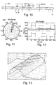
- FIG. 11 An example of a profile plot of a scan is given in the Figures 11 and 12 shown.
- Figure 11 a profile plot in polar coordinates is shown.
- Figure 12 the same circumferential profile is plotted in a Cartesian coordinate system as a radius over the angle or as a function of the angle.
- the faulty flattening of the profile and thus of the product strand in the range between 0 ° and 120 ° can be clearly seen.
- FIG. 13 An example of a 3D profile plot which is composed of several individual profile plots according to FIG. 11 one behind the other in the production direction is shown in FIG Figure 13 shown.
- the graphic only shows the partial profile corresponding to an image sensor.
- the complete 360 ° profile can also be displayed.
- a thickening in the rear area can be seen in the image; this can be, for example, a single segment of greater thickness.
- a longitudinal fold is visible in the light area of the front edge.
- a line of light or a light-dark edge in particular composed of structured light, can also be used.
Description
Die vorliegende Erfindung betrifft eine optische Messvorrichtung zur Ermittlung mindestens eines Merkmals, Qualitätswerts und/oder von Servicedaten eines endlos verarbeiteten Produktstrangs der Tabak verarbeitenden Industrie auf der Grundlage der Triangulation, umfassend mindestens eine Lichtquelle zur Erzeugung einer Mehrzahl von einfallenden Strahlengängen, die um den Umfang des Produktstrangs herum auf dessen Oberfläche fallen, mindestens drei lichtempfindliche Elemente, die relativ zu den einfallenden Strahlengängen in einer Triangulationsanordnung angeordnet sind, und eine digitale Auswerteeinrichtung, die zur Ermittlung eines 3-dimensionalen Oberflächenprofils des Produktstrangs aus den von den lichtempfindlichen Elementen übermittelten Messsignalen eingerichtet ist. Die Erfindung betrifft des Weiteren die Verwendung einer solchen optischen Messvorrichtung, und ein entsprechendes optisches Messverfahren.The present invention relates to an optical measuring device for determining at least one feature, quality value and / or service data of an endlessly processed product strand of the tobacco processing industry on the basis of triangulation, comprising at least one light source for generating a plurality of incident beam paths that surround the circumference of the The product strand falls on its surface, at least three light-sensitive elements that are arranged in a triangulation arrangement relative to the incident beam paths, and a digital evaluation device that is set up to determine a 3-dimensional surface profile of the product strand from the measurement signals transmitted by the light-sensitive elements. The invention also relates to the use of such an optical measuring device and a corresponding optical measuring method.
Zur Ermittlung unter anderem des Durchmessers eines Tabakstrangs in einer Zigarettenherstellmaschine ist eine optische Messeinrichtung nach dem Schattenwurfprinzip aus der
Aufgrund neuer Produkte und höherem Bedarf an Produktinformationen wird die Forderung gestellt, Strangprofile und somit unter anderem auch Durchmesserwerte in wesentlich kürzeren Abständen zu erhalten. Ein weiteres Ziel ist die Vermeidung von bewegten Teilen in der Messvorrichtung, um den Verschleiß zu verringern, und den Platzbedarf der Messvorrichtung zu verkleinern.Due to new products and a greater need for product information, there is a demand to obtain extruded profiles and thus, among other things, diameter values at significantly shorter intervals. Another aim is to avoid moving parts in the measuring device in order to reduce wear and tear and to reduce the space required by the measuring device.
Nachdem der Endlosstrang die Messvorrichtung durchlaufen hat, wird er mittels eines Schneidapparats in gleichlange Stäbe geteilt. Jeder Stab kann in manchen Anwendungen aus unterschiedlichen Materialien segmentweise zusammengesetzt sein. Die durchlaufenden Segmente sind in Regel mit Umhüllungspapier geschlossen. Das Profil wird aber durch die innenliegenden Segmente ausgeprägt. Für jedes Segmentstück werden Qualitätsparameter, unter anderem Durchmesser, Ovalität etc., benötigt, um Qualitäten der Gesamtproduktion und Produktionsabläufe zu überprüfen und zu optimieren. Derzeit sind für diese Messaufgabe keine Messsysteme verfügbar.After the endless strand has passed through the measuring device, it is divided into rods of equal length by means of a cutting device. Each rod can be used in some applications be composed of different materials in segments. The continuous segments are usually closed with wrapping paper. The profile is defined by the internal segments. Quality parameters, including diameter, ovality, etc., are required for each segment piece in order to check and optimize the quality of the overall production and production processes. There are currently no measurement systems available for this measurement task.
Die
Die
Die
Die
Die der Erfindung zugrundeliegende Aufgabe besteht darin, eine Messvorrichtung bereitzustellen, bei der der Verschleiß verringert und der Platzbedarf verkleinert ist und die für jeden Stab, und im Falle eines Multisegmentstabs für jedes Segmentstück, geforderte oder gewünschte Qualitätswerte, Merkmale und/oder Serviceinformationen bereitstellt.The object on which the invention is based is to provide a measuring device in which wear is reduced and the space requirement is reduced and which provides required or desired quality values, features and / or service information for each rod, and in the case of a multi-segment rod for each segment piece.
Die Erfindung löst diese Aufgabe mit den Merkmalen der unabhängigen Ansprüche.The invention solves this problem with the features of the independent claims.
Zur Profilmessung des Produktstrangs um dessen Umfang herum wird vom Messprinzip der optischen Triangulation, d.h. vom Lichtschnittverfahren, Gebrauch gemacht. Dabei wird das einfallende Licht rund um den gesamten Umfang des Produktstrangs herum, d.h. um die vollen 360°, auf dessen Oberfläche projiziert und erzeugt dort eine scharfe Lichtlinie rund um den Produktstrang herum. Eine Mehrzahl von lichtempfindlichen Elementen sind erfindungsgemäß relativ zu den einfallenden Strahlengängen in einer Triangulationsanordnung angeordnet, um jeweils ein Teilprofil des Produktstrangs aufzunehmen.The measuring principle of optical triangulation, i.e. the light section method, is used to measure the profile of the product strand around its circumference. The incident light is projected around the entire circumference of the product strand, i.e. around the full 360 °, onto its surface, where it creates a sharp line of light around the product strand. According to the invention, a plurality of light-sensitive elements are arranged in a triangulation arrangement relative to the incident beam paths, in order in each case to record a partial profile of the product strand.
Es sind dabei mindestens drei lichtempfindliche Elemente vorgesehen, um alle Punkte eines Strangprofils um den gesamten Umfang herum erfassen zu können und auch für die jeweiligen Randbereiche des Produktstrangs, von einem lichtempfindlichen Element aus betrachtet, aussagekräftige Bildinformation zu erhalten. Sämtliche lichtempfindlichen Elemente nehmen einen definierten Winkelbereich des Strangprofils vorteilhaft gleichzeitig auf. Aus den vom Produktstrang reflektierten und von den lichtempfindlichen Elementen aufgenommenen Lichtlinien kann ein 360°-Umfangsprofil erstellt werden.At least three light-sensitive elements are provided in order to be able to detect all points of an extruded profile around the entire circumference and also to obtain meaningful image information for the respective edge areas of the product strand, viewed from a light-sensitive element. All light-sensitive elements take up a defined angular range of the extruded profile advantageously at the same time. A 360 ° circumferential profile can be created from the light lines reflected from the product strand and picked up by the light-sensitive elements.
Erfindungsgemäß weist die optische Messvorrichtung mindestes ein Lichtumlenkungselement zwischen der Lichtquelle und dem Produktstrang zur Umlenkung mindestens eines einfallenden Strahlengangs, und/oder zwischen dem Produktstrang und mindestens einem lichtempfindlichen Element zur Umlenkung mindestens eines auslaufenden Strahlengangs auf. Auf diese Weise können die Lichtquelle, die lichtempfindlichen Elemente und/oder weitere optische Elemente an gewünschter Stelle platziert werden, was eine besonders kompakte bzw. bauraumsparende Anordnung ermöglicht.According to the invention, the optical measuring device has at least one light deflection element between the light source and the product strand for deflecting at least one incident beam path, and / or between the product strand and at least one light-sensitive element for deflecting at least one outgoing beam path. In this way, the light source, the light-sensitive elements and / or further optical elements can be placed at the desired location, which enables a particularly compact or space-saving arrangement.
Vorteilhaft kann in jedem auslaufenden Strahlengang mindestens ein Lichtumlenkungselement angeordnet sein, was die Freiheit in der Anordnung der optischen Elemente noch erhöht.At least one light deflection element can advantageously be arranged in each exiting beam path, which further increases the freedom in the arrangement of the optical elements.
Der Begriff Strahlengang ist dabei möglichst breit zu verstehen und umfasst dabei sowohl die einfallenden Strahlengänge zwischen der Lichtquelle und dem Produktstrang, die auslaufenden Strahlengänge zwischen dem Produktstrang und den lichtempfindlichen Elementen, als auch (Teil-)Strahlengänge zwischen Lichtquelle, Produktstrang, lichtempfindlichen Elementen und Strahlumlenkungselementen.The term beam path is to be understood as broadly as possible and includes both the incident beam paths between the light source and the product strand, the outgoing beam paths between the product strand and the light-sensitive elements, and (partial) beam paths between the light source, product strand, light-sensitive elements and beam deflection elements .
Vorzugsweise ist die Anzahl der Lichtquellen geringer als die Anzahl der lichtempfindlichen Elemente, und erfindungsgemäß weist die Messvorrichtung genau eine Lichtquelle auf, was besonders kostengünstig ist. Dies wird ermöglicht, indem der von der Lichtquelle ausgehenden Lichtstrahl geeignet umgelenkt wird, um eine Mehrzahl von auf den Produktstrang einfallenden Lichtstrahlen bzw. Lichtfächern zu erzeugen.The number of light sources is preferably less than the number of light-sensitive elements, and according to the invention the measuring device has exactly one light source, which is particularly cost-effective. This is made possible in that the light beam emanating from the light source is suitably deflected in order to generate a plurality of light beams or light fans incident on the product strand.
Erfindungsgemäß erzeugt die Lichtquelle einen Hauptstrahlungsfächer, wobei ein Teil des Hauptstrahlungsfächers auf den Produktstrang fällt und ein anderer Teil des Hauptstrahlungsfächers an einer oder beiden Seiten des Produktstrangs an diesem vorbeiläuft und nach dem Passieren des Produktstrangs mit mindestens einem Lichtumlenkungselement auf den Produktstrang gerichtet wird.According to the invention, the light source generates a main radiation fan, with part of the main radiation fan falling on the product strand and another part of the main radiation fan running past one or both sides of the product strand and, after the product strand has passed, is directed onto the product strand with at least one light deflecting element.
Vorzugsweise weist die optische Messvorrichtung mindestens drei um den Umfang des Produktstrangs herum angeordnete einfallende Strahlengänge auf, um eine möglichst gleichmäßige und helle Ausleuchtung des Produktstrangs um dessen gesamten Umfang herum zu ermöglichen. Genau drei auf den Produktstrang einfallende Strahlengänge können zu diesem Zweck ausreichen.The optical measuring device preferably has at least three incident beam paths arranged around the circumference of the product strand in order to enable the most uniform and bright possible illumination of the product strand around its entire circumference. Exactly three beam paths incident on the product strand can be sufficient for this purpose.
Es ist alternativ auch möglich, eine Mehrzahl von Lichtquellen zur Erzeugung der auf den Produktstrang einfallenden Strahlengänge vorzusehen.Alternatively, it is also possible to provide a plurality of light sources for generating the beam paths incident on the product strand.
Vorteilhaft ist eine Kollimatorlinse im einfallenden Strahlengang angeordnet, um die einfallenden Strahlen zu parallelisieren und somit im Messfeld eine gleichmäßige Strahldichte bzw. Ausleuchtung der Strangoberfläche zu erhalten. Es sind jedoch auch Umsetzungen ohne Kollimatorlinse möglich.A collimator lens is advantageously arranged in the incident beam path in order to parallelize the incident beams and thus obtain a uniform radiance or illumination of the strand surface in the measuring field. However, implementations without a collimator lens are also possible.
Aus dem mit der optischen Messvorrichtung gemessenen bzw. errechneten dreidimensionalen Oberflächenprofil des Produktstrangs können zahlreiche gewünschte Qualitätswerte, Merkmale und/oder Servicedaten ermittelt werden.Numerous desired quality values, features and / or service data can be determined from the three-dimensional surface profile of the product strand measured or calculated with the optical measuring device.
Zu den ermittelbaren Qualitätswerten zählen beispielsweise Durchmesser und Umfang des Produktstrangs; Ovalität; Unrundheitsfaktor, z.B. Standardabweichung der Radien eines Strangprofils; Nahtlage eines Umhüllungsstreifens, beispielsweise als Winkel. Qualitätswerte werden vorteilhaft je Stab, je Segment und/oder als Mittelwert für die Produktion berechnet und angegeben. Generell können eine oder mehrere Standardabweichungen (oder Varianzen) einer oder mehrerer der vorgenannten Größen aussagekräftige Information enthalten und zur weiteren Verarbeitung ermittelt werden.The ascertainable quality values include, for example, the diameter and circumference of the product strand; Ovality; Out-of-roundness factor, eg standard deviation of the radii of an extruded profile; Seam position of a wrapping strip, for example as an angle. Quality values are advantageously calculated and specified for each bar, for each segment and / or as an average value for production. In general, one or more standard deviations (or variances) of one or more of the aforementioned variables can contain meaningful information and can be determined for further processing.
Zu ermittelnde Merkmale des Produktstrangs sind insbesondere solche, die sich im Produkt, d.h. im geschnittenen Strang, als Fehler bemerkbar machen. Merkmale dieser Art sind beispielsweise Profilfehler an Teilstücken des Strangs und/oder an Einzelsegmenten; Klebstellen eines Umhüllungsstreifens im Endlosstrangverlauf; Klebstellenfehler einer Klebenaht an Teilstücken des Strangs; Fremdkörperanhaftungen an einem Strangstück.Features of the product strand to be determined are in particular those that are noticeable as defects in the product, i.e. in the cut strand. Features of this type are, for example, profile defects on sections of the strand and / or on individual segments; Adhesive points of a wrapping strip in the continuous strand course; Glued joint defects in a glued seam on sections of the strand; Foreign body build-up on a piece of string.
Vorteilhaft zu ermittelnde Servicedaten sind beispielsweise Strangschwingen; unruhige Längsnaht eines Umhüllungsstreifens, beispielsweise als Standardabweichung über die Produktion; Profilplot; 3D-Plot.Service data to be determined advantageously are, for example, string swinging; restless longitudinal seam of a wrapping strip, for example as a standard deviation over production; Profile plot; 3D plot.
Nach dem zuvor Gesagten sind die lichtempfindlichen Elemente vorteilhaft positions-sensitive bildgebende Sensoren, insbesondere CMOS-Sensoren, um die Anwendung des Triangulationsverfahrens in der Datenauswertung zu ermöglichen.According to what has been said above, the light-sensitive elements are advantageously position-sensitive imaging sensors, in particular CMOS sensors, in order to enable the triangulation method to be used in data evaluation.
Bevorzugt ist es, wenn die einfallenden Lichtstrahlen lotrecht auf den Produktstrang einfallen, um eine geschlossene Lichtlinie um den Umfang des Produktstrangs zu erhalten.It is preferred if the incident light rays fall perpendicularly onto the product strand in order to obtain a closed line of light around the circumference of the product strand.
Vorteilhaft ist die Bildebene der lichtempfindlichen Elemente schräg zu der jeweiligen optischen Achse, d.h. der optischen Achse des entsprechenden Objektivs angeordnet. Eine solche Anordnung nach der Scheimpflug-Regel ermöglicht es, in der Bildebene der zu messenden Profilebene optimal scharfe Bilder zu erzeugen.The image plane of the light-sensitive elements is advantageously arranged at an angle to the respective optical axis, i.e. the optical axis of the corresponding objective. Such an arrangement according to the Scheimpflug rule makes it possible to generate optimally sharp images in the image plane of the profile plane to be measured.
Die Abtastrate der Messvorrichtung ist vorteilhaft ausreichend hoch und insbesondere so hoch gewählt, dass der axiale Abstand zwischen zwei Messprofilen kleiner oder gleich der kürzesten Segmentlänge in dem Produktstrang ist. Dies ermöglicht es, für jedes Segment in dem Produktstrang mindestens ein Messprofil zu erhalten.The sampling rate of the measuring device is advantageously sufficiently high and in particular selected so high that the axial distance between two measuring profiles is less than or equal to the shortest segment length in the product strand. This makes it possible to obtain at least one measurement profile for each segment in the product line.
Jedem lichtempfindlichen Element kann vorteilhaft eine Steuerung, insbesondere ein FPGA und/oder ein Mikroprozessor, zur Vorverarbeitung, Vorauswertung und/oder Datenverdichtung der Signale von dem lichtempfindlichen Element zugeordnet sein. In dieser Ausführungsform Fall werden die Daten sämtlicher Steuerungen vorteilhaft zu einer Hauptsteuerungs- und/oder Datenzusammenfassungseinheit, insbesondere ein FPGA und/oder ein Mikroprozessor, zur Weiterverarbeitung gesendet.Each light-sensitive element can advantageously be assigned a controller, in particular an FPGA and / or a microprocessor, for preprocessing, pre-evaluation and / or data compression of the signals from the light-sensitive element. In this embodiment case, the data of all controls are advantageously a main control and / or data aggregation unit, in particular an FPGA and / or a microprocessor, sent for further processing.
Ein erfindungsgemäßes Messmodul umfasst vorteilhaft eine vorbeschriebene optische Messvorrichtung und ein die Messvorrichtung umgebendes Gehäuse mit Durchgangsöffnungen zum Durchführen des Produktstrangs durch das Messmodul. In diesem Fall sind die vorbeschriebenen Steuerungen und die Hauptsteuerungsund/oder Datenzusammenfassungseinheit vorteilhaft ebenfalls in dem Messmodul angeordnet. Besonders vorteilhaft ist es, wenn der Abstand einer Durchgangsöffnung zur nächstgelegenen Gehäusekante kleiner oder gleich dem halben Abstand zweier in einer Zweistrangmaschine zu verarbeitender Produktstränge ist. In diesem Fall können zwei identisch aufgebaute Messmodule verwendet, wobei das zweite Messmodul gegenüber dem ersten um 180° gedreht angeordnet ist.A measuring module according to the invention advantageously comprises a previously described optical measuring device and a housing surrounding the measuring device with passage openings for leading the product strand through the measuring module. In this case, the controls described above and the main control and / or data summarizing unit are advantageously also arranged in the measuring module. It is particularly advantageous if the distance between a through opening and the nearest housing edge is less than or equal to half the distance between two product strands to be processed in a two-strand machine. In this case, two identically constructed measuring modules can be used, the second measuring module being arranged rotated by 180 ° with respect to the first.
Die Erfindung schlägt weiterhin die Verwendung einer vorbeschriebenen optischen Messvorrichtung zur Messung von Qualitätswerten, Merkmalen und/oder Servicedaten einzelner Segmente in sich endlos wiederholenden Multisegment-Stababschnitten eines Produktstrangs.The invention also proposes the use of a previously described optical measuring device for measuring quality values, features and / or service data of individual segments in endlessly repeating multi-segment rod sections of a product strand.
Nach einem weiteren Aspekt der Erfindung wird ein Verfahren zur optischen Messung von Qualitätswerten, Merkmalen und/oder Servicedaten eines endlos verarbeiteten Produktstrangs der Tabak verarbeitenden Industrie mittels einer vorbeschriebenen optischen Messvorrichtung vorgeschlagen, wobei die Messung vorteilhaft synchron zur Teilung des Produktstrangs in Stäbe und/oder Stabsegmente und/oder synchron zur Produktionsgeschwindigkeit erfolgt.According to a further aspect of the invention, a method for the optical measurement of quality values, features and / or service data of an endlessly processed product strand of the tobacco processing industry by means of an optical measuring device described above is proposed, the measurement advantageously being synchronized with the division of the product strand into bars and / or bar segments and / or takes place synchronously with the production speed.
Die Erfindung wird im Folgenden anhand bevorzugter Ausführungsformen unter Bezugnahme auf die beigefügten Figuren erläutert. Dabei zeigt
- Fig. 1
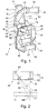
- eine perspektivische Ansicht einer optischen Messvorrichtung;
- Fig. 2
- eine schematische Darstellung zur Illustration des verwendeten Triangulations- bzw. Lichtschnittverfahrens;
- Fig. 3
- eine perspektivische Ansicht auf eine Lichterzeugungsanordnung in einer optischen Messvorrichtung;
- Fig. 4
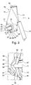
- eine perspektivische Detailansicht des zentralen Bereichs der optischen Messvorrichtung aus
Figur 1 ; - Fig. 5
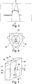
- eine perspektivische Draufsicht auf einen Produktstrang mit beispielhaft aufprojizierter Laserlinie;
- Fig. 6
- einen schematischen Querschnitt durch den Produktstrang mit äquidistanter Anordnung der lichtempfindlichen Elemente;
- Fig. 7
- eine perspektivische schematische Ansicht zweier Messmodule für eine Zweistrangmaschine;
- Fig. 8
- eine perspektivische Ansicht einer Zigarettenherstellmaschine mit in der Verteilereinheit angeordnetem Messmodul;
- Fig. 9
- ein schematisches Diagramm zur Illustration der Datenverarbeitung und -auswertung ausgehend von einer Messvorrichtung;
- Fig. 10
- eine schematische Darstellung eines aus Multisegmentstäben zusammengesetzten Produktstrangs;
- Fig. 11, 12
- beispielhafte Profilplots in Polarkoordinaten bzw. kartesischen Koordinaten; und
- Fig. 13
- einen beispielhaften 3D-Profilplot.
- Fig. 1
- a perspective view of an optical measuring device;
- Fig. 2
- a schematic representation to illustrate the triangulation or light section method used;
- Fig. 3
- a perspective view of a light generating arrangement in an optical measuring device;
- Fig. 4
- a perspective detailed view of the central area of the optical measuring device
Figure 1 ; - Fig. 5
- a perspective top view of a product strand with a laser line projected onto it by way of example;
- Fig. 6
- a schematic cross section through the product strand with equidistant arrangement of the light-sensitive elements;
- Fig. 7
- a perspective schematic view of two measuring modules for a two-line machine;
- Fig. 8
- a perspective view of a cigarette manufacturing machine with a measuring module arranged in the distribution unit;
- Fig. 9
- a schematic diagram to illustrate the data processing and evaluation based on a measuring device;
- Fig. 10
- a schematic representation of a product strand composed of multi-segment rods;
- Figures 11, 12
- exemplary profile plots in polar coordinates or Cartesian coordinates; and
- Fig. 13
- an exemplary 3D profile plot.
Die Messvorrichtung 10 dient zur Messung eines dreidimensionalen 360°-Oberflächenprofils eines endlos verarbeiteten Produktstrangs 11 der Tabak verarbeitenden Industrie, beispielsweise eines Tabakstrangs, eines Filterstrangs oder eines Multisegmentfilterstrangs. Der Produktstrang 11 wird in einer Strangmaschine 83 der Tabak verarbeitenden Industrie längsaxial gefördert, siehe Beschreibung der
In
Die Umlenkung durch das Umlenkungselement 14 erfolgt vorteilhaft um einen Winkel von mindestens 90°, weiter vorteilhaft mindesten 135°, beispielsweise im Winkelbereich zwischen 135° und 180°.The deflection by the
Der aufweitete und gegebenenfalls kollimierte einfallende Strahlengang 16 wird vorteilhaft mithilfe von Spiegeln 24, 25 von zwei zusätzlichen, und somit insgesamt drei Seiten auf den Strang 11 projiziert, um eine um den Umfang des Strangs 11 umlaufende Lichtlinie 21 zu erhalten. Dies wird im Folgenden genauer anhand der
Der einfallende, vorteilhaft parallele Strahlengang 16, 18 fällt in einem mittleren Bereich 19, der als Hauptstrahlungsfächer bezeichnet werden kann, auf den Produktstrang 11. Zuvor durchquert der parallelisierte Lichtfächer 18 noch ein für das Laserlicht transparentes Schutzrohr 20, das beispielsweise aus Glas bestehen kann und im Bereich der Messstelle um den Umfang des Produktstrangs 11 herum angeordnet ist, um die Bildsensoren 29-31 der Kameras 35-37 (siehe
Der mittlere Bereich 19 des auf den Produktstrang 11 einfallenden Lichtfächers 18 erzeugt auf der Oberfläche des Produktstrangs 11, insbesondere auf einem Hüllmaterial desselben, eine Laserlichtlinie 21, wie dies bespielhaft in
Der parallelisierte Lichtfächer 18 hat eine Gesamtbreite B, die mindestens das 3-fache, vorteilhaft mindestens das 4-fache, noch weiter vorteilhaft mindestens das 5-fache der Breite b des Produktstrangs 11 beträgt, siehe
Auf der Rückseite des Produktstrangs 11, von dem einfallenden Strahlungsfächer 15, 18 bzw. einfallenden Strahlengang 16 aus betrachtet, ist auf einer oder vorzugsweise beiden Seiten des Produktstrangs 11 jeweils ein weiteres Umlenkelement 24, 25 vorgesehen, das jeweils einen der seitlichen Bereiche 22, 23 des Strahlungsfächers 18 so umlenkt, dass dieser als einfallende Strahlenfächer 26, 27 von der Rückseite her auf die Oberfläche des Produktstrangs 11 fällt. Vorteilhaft erfolgt die Umlenkung durch jedes Umlenkelement 24, 25 um einen Winkel im Bereich 120° bis 180°, beispielsweise um 150°. Auf diese Weise, oder durch eine andere geeignete Strahlumlenkung, wird erreicht, dass die zentralen Strahlachsen aller drei auf den Produktstrang einfallenden Strahlenfächer 19, 26, 27 Winkel von 120° zueinander einschließen.On the rear side of the
Wie in
Die um den Produktstrang 11 auf deren Oberfläche umlaufende Laserlinie 21 wird mittels optischer Triangulation aufgenommen. Zu diesem Zweck ist eine Mehrzahl von lichtempfindlichen Elementen 29, 30, 31 um den Produktstrang herum angeordnet, siehe
Im Folgenden wird das verwendete Messprinzip der Lasertriangulation am Beispiel eines einfallenden Lichtfächers bzw. Lichtstrahls 19 und eines entsprechenden lichtempfindlichen Elements 29 anhand der
Mithilfe der Laserlichtquelle 12 wird, wie zuvor beschrieben, eine in Strangrichtung sehr dünne Laserlinie, bzw. ein Laserlichtfächer, auf den Produktstrang 11 gerichtet. Der einfallende Lichtstrahl bzw. Lichtfächer 16, 19 fällt in einer Ansicht quer zum Produktstrang 11 (siehe
Jedem lichtempfindlichen Element 29-31 ist vorteilhaft ein entsprechendes Objektiv 32-34 zugeordnet, siehe
Zwischen dem Produktstrang 11 und jeder Kamera 35-37 sind vorteilhaft ein oder mehrere Strahlumlenkungselemente 41-49 angeordnet. Dadurch können die Kameras 35-37 je nach zur Verfügung stehendem Bauraum optimal angeordnet werden, um ein möglichst kompaktes und an die jeweilige Einbausituation optimal angepasstes Messmodul 50, 51 (siehe
Im Folgenden wird ein auslaufender Strahlengang 38 zu dem lichtempfindlichen Element 29 beispielhaft beschrieben. Vergleichbares gilt jeweils für die weiteren auslaufenden Strahlengänge 39, 40 zu den lichtempfindlichen Elementen 30, 31.In the following, an
In dem auslaufenden Strahlengang 38 zu dem lichtempfindlichen Element 29 sind in der Ausführungsform nach
Ausgehend von der Oberfläche des Produktstrangs 11 kann zunächst ein erstes Strahlumlenkungselement 41 vorgesehen sein, das den beispielsweise unter dem Triangulationswinkel α auslaufenden Strahl 38 so umlenkt, dass der umgelenkte Strahl 52 in einem Winkel zwischen 75° und 105°, beispielsweise um 90° relativ zu der Strangachse verläuft. Dies ist am besten in
Der von dem ersten Strahlumlenkungselement 41 umgelenkte Lichtstrahl 52 wird durch mindestens ein, hier zwei weitere Strahlumlenkungselemente 42, 43 so umgelenkt, dass der auslaufende Lichtstrahl 38 schließlich in die Kamera 35 eintritt. Die gesamte Umlenkung durch das mindestens eine weitere Strahlumlenkungselement 42, 43 beträgt vorteilhaft mindestens 90° und beispielsweise 135° oder, wie im Fall des lichtempfindlichen Elements 31, sogar 180°.The
Die lichtempfindlichen Elemente 29, 30, 31 sind vorteilhaft um gleiche Winkelabstände zueinander, im bevorzugten Fall von drei lichtempfindlichen Elementen 29, 30, 31 somit um jeweils 120° versetzt um den Produktstrang 11 herum angeordnet. Dies ist in
Wenn im jeweiligen auslaufenden Strahlengang 38-40 zwischen dem Produktstrang 11 und dem jeweiligen lichtempfindlichen Element 29-31 jeweils ein oder mehrere Strahlumlenkungselemente 41-49 angeordnet sind, sind die auslaufenden Strahlengänge 38-40 vorteilhaft um gleiche Winkelabstände zueinander um den Produktstrang 11 herum angeordnet. In diesem Fall kommt es nicht auf die Winkelabstände der lichtempfindlichen Elemente 29-31 an, die aufgrund der Lichtumlenkungselemente 41-49 abweichend angeordnet sein können.If one or more beam deflection elements 41-49 are arranged in the respective outgoing beam path 38-40 between the
Wie zuvor beschrieben werden die Strahlengänge ausgehend von der Laserlichtquelle 12 bis hin zu den Bildaufnehmern 29-31 über eine Mehrzahl von Spiegeln 14, 24, 25, 41-49 umgelenkt, um die einzelnen Bauteile 12, 29-31 optimal platzieren zu können.As described above, the beam paths are deflected starting from the
Durch Kombination von hier drei Laserlinien 21 über jeweils 120° Umfangsbereich des Produktstrangs 11 (allgemein n Laserlinien um jeweils 360°/n Umfangsbereich des Produktstrangs 11) wird daher eine vollständiges dreidimensionales 360°-Profil der Oberfläche des Produktstrangs 11, d.h. um den gesamten Umfang des Produktstrangs 11, erhalten.By combining here three
Die Messvorrichtung 10 ist vorteilhaft von einem Gehäuse 53 umgeben und bildet somit ein Messmodul 50, 51. In der
Die Anordnung der Durchgangsöffnungen 54, 55 in dem Gehäuse 53 kann asymmetrisch sein. Insbesondere können die Durchgangsöffnungen 54, 55 mit einem wesentlich kleineren Abstand d zu einer nächstliegenden Gehäusekante 56 bzw. 57 oder Gehäusewand 58 angeordnet sein als zu jeder anderen Gehäusekante oder Gehäusewand. Besonders vorteilhaft ist der Abstand d höchstens halb so groß wie der Abstand D der beiden Stränge in einer Zweistrangmaschine. In diesem Fall kann könne identisch aufgebaute, lediglich um 180° gegeneinander verdreht angeordnete Messmodule verwendet werden, wie in
In der
Eine vorteilhafte Position der Messvorrichtung 10 oder des Messmoduls 50 in der Strangeinheit ist in Strangförderrichtung zwischen einer Umhüllungseinrichtung 59 zur Umhüllung des Materialstrangs mit einem Umhüllungsstreifen, beispielsweise Papier, und einem Schneidapparat 60 zum fortlaufenden Zerschneiden des Endlosstrangs 11 in einzelne stabförmige Elemente.An advantageous position of the measuring
Im Folgenden wird die Messdatenaufbereitung in dem Messmodul 50 und die weitere Datenverarbeitung anhand von
Das Messmodul 50 umfasst, wie zuvor beschrieben, mindestens drei lichtempfindliche Elemente bzw. bildgebende Sensoren 29-31, die beispielsweise um jeweils 120° versetzt um den Produktstrang 11 herum angeordnet sind. Jedem Sensor 29-31 kann eine Steuerung 61 beispielsweise in Form eines FPGA und/oder Microcontroller, zugeordnet sein, die insbesondere zur Vorauswertung und/oder zur Datenverdichtung dienen kann. Die Daten der einzelnen Bildsensor-Module werden über eine entsprechend schnelle Datenverbindung 62 an eine Hauptsteuerungs- oder Datenzusammenfassungseinheit 63, beispielsweise ebenfalls ein FPGA und/oder Microcontroller, übertragen. Das Sensormodul 50 stellt nun über eine schnelle Datenverbindung 64 Profilwerte des Produktstrangs 11 beispielsweise als Polarkoordinaten oder kartesischen Koordinaten einer folgenden Auswerteeinheit 65 zur Verfügung.As described above, the measuring
Dabei werden in einer Recheneinheit 66, die die Sensordaten von dem Sensormodul 50 empfängt, in Verbindung mit der Maschinensteuerung 67 aus den Sensordaten Qualitätswerte, spezielle Merkmale des Strangs und/oder Servicedaten generiert. Die Daten werden vorteilhaft für die Maschinenvisualisierung und/oder Parametrierung 68 und/oder die Steuerung und/oder Regelung des Herstellungsprozesses, insbesondere über Stellglieder 69 für Regelung und/oder Stellglieder 70 für Produktselektion oder Produktausschuss, genutzt, um eine höhere Produktqualität und eine effizientere Laufzeit der Herstellmaschine zu erhalten. Die Hauptsteuerungsoder Datenzusammenfassungseinheit 63 und/oder die Recheneinheit 66 gemäß Figur 9 bilden vorteilhaft eine digitale Auswerteeinrichtung 73 gemäß den Patentansprüchen.In this case, quality values, special features of the strand and / or service data are generated from the sensor data in a
Über entsprechende Datenkanäle können die Informationen auch zur Datensammlung und Analyse in einem übergeordneten Datensammler 71, sowie zur Steuerung und/oder Regelung vorgeschalteter Maschinen 72 genutzt werden, um auch dort die Qualität der der Herstellmaschine zuzuliefernden Teile zu erhöhen.Via corresponding data channels, the information can also be used for data collection and analysis in a higher-
In einer alternativen Ausführungsform, in der die Rechenleistung der Hauptsteuerungs- oder Datenzusammenfassungseinheit 63 ausreichend groß ist, könne auch dort schon aus den Sensordaten Qualitätswerte, spezielle Merkmale des Strangs und/oder Servicedaten errechnet und für Visualisierung 68 und Weiterverarbeitung über geeignete Datenkanäle bereitgestellt werden.In an alternative embodiment, in which the computing power of the main control or
Eine vorteilhafte Anwendung der Messvorrichtung 10 dient zur Messung von Qualitätswerten, Merkmalen und/oder Servicedaten einzelner Segmente in sich endlos wiederholenden Multisegment-Stababschnitten eines Produktstrangs 11. Dies sei im Folgenden anhand von
Der endlos verarbeitete Produktstrang ist aus sich fortlaufend wiederholenden Stababschnitten ..., Sn, Sn+1, Sn+2, ... gebildet. Jeder Stabschnitt entspricht einem Stab nach dem Zerschneiden des Produktstrangs 11 in einzelne Stäbe mittels dem Schneidapparat 60 (siehe
Jeder Stab bzw. Stababschnitt Sn ist in dieser Anwendung wiederum aus einer gleichen Folge von Segmenten T1, T2, T3, ... zusammengesetzt, wobei die Summe der Segmentlängen die Stablänge ergibt. Im vorliegenden Fall weist jeder Stab drei Segmente T1, T2, T3 auf, wobei mehr oder weniger als drei Segmente pro Stab möglich sind. Es handelt sich hier also um Multisegment-Stäbe.In this application, each rod or rod section Sn is in turn composed of the same sequence of segments T1, T2, T3, ..., the sum of the segment lengths giving the rod length. In the present case, each rod has three segments T1, T2, T3, with more or less than three segments per rod being possible. It is therefore a question of multi-segment bars.
Wie aus
Aus
Aus den ermittelten Umfangsprofilen können diverse Qualitätsdaten, Merkmale des Produktstrangs 11 und Servicewerte ermittelt werden.Various quality data, features of the
Qualitätswerte werden vorteilhaft je Stab, je Segment und/oder als Mittelwert für die Produktion berechnet und angegeben. Dazu zählen beispielsweise Durchmesser und Umfang des Produktstrangs 11; Ovalität; Unrundheitsfaktor, z.B. Standardabweichung der Radien eines Strangprofils; Nahtlage eines Umhüllungsstreifens, beispielsweise als Winkel.Quality values are advantageously calculated and specified for each bar, for each segment and / or as an average value for production. These include, for example, the diameter and circumference of the
Generell können eine oder mehrere Standardabweichungen (oder Varianzen) einer oder mehrerer der vorgenannten Größen aussagekräftige Information enthalten und zur weiteren Verarbeitung ermittelt werden. Werden etwa aus Einzelwerten Mittelwerte gebildet, so ist eine gleichzeitige Angabe einer Standardabweichung sinnvoll, beispielsweise um frühzeitig Hinweise auf eine unruhiger werdende Produktion und bevorstehende Fehler, z.B. durch Maschinenverschmutzung, zu erhalten und rechtzeitig darauf reagieren zu können.In general, one or more standard deviations (or variances) of one or more of the aforementioned variables can contain meaningful information and can be determined for further processing. If, for example, mean values are formed from individual values, then a simultaneous specification of a standard deviation is useful, for example in order to provide early indications that production is becoming more restless and To receive upcoming errors, e.g. due to machine contamination, and to be able to react to them in good time.
Zu ermittelnde Merkmale des Produktstrangs sind insbesondere solche, die sich im Produkt, d.h. im geschnittenen Strang, als Fehler bemerkbar machen. Ein fehlerhaftes Produkt wird dann vorteilhaft aus der Produktion selektiert bzw. entfernt. Merkmale dieser Art sind beispielsweise Profilfehler an Teilstücken des Strangs und/oder an Einzelsegmenten; Klebstellen eines Umhüllungsstreifens im Endlosstrangverlauf; Klebstellenfehler einer Klebenaht an Teilstücken des Strangs; Fremdkörperanhaftungen an einem Strangstück.Features of the product strand to be determined are in particular those that are noticeable as defects in the product, i.e. in the cut strand. A defective product is then advantageously selected or removed from production. Features of this type are, for example, profile defects on sections of the strand and / or on individual segments; Adhesive points of a wrapping strip in the continuous strand course; Glued joint defects in a glued seam on sections of the strand; Foreign body build-up on a piece of string.
Serviceinformationen sind für Maschineneinrichter, Servicepersonal und Maschinenbediener wichtig, um Aussagen über eine zuverlässige Produktion zu erhalten und gegebenenfalls korrigierend in den Fertigungsprozess eingreifen zu können. Servicedaten dieser Art sind beispielsweise Strangschwingen; unruhige Längsnaht eines Umhüllungsstreifens, beispielsweise als Standardabweichung über die Produktion; Profilplot; 3D-Plot.Service information is important for machine setters, service personnel and machine operators in order to obtain information about reliable production and, if necessary, to be able to intervene in the production process to correct it. Service data of this type are, for example, string swing; restless longitudinal seam of a wrapping strip, for example as a standard deviation over production; Profile plot; 3D plot.
Ein Beispiel für einen Profilplot eines Scans ist in den
Ein Beispiel für einen 3D-Profilplot, der aus mehreren Einzelprofil-Plots gemäß Figur 11 in Produktionsrichtung hintereinander zusammengesetzt ist, ist in
Anstelle einer Laserlinie 21 kann auch eine Lichtlinie oder eine Hell-Dunkel-Kante insbesondere aus strukturiertem Licht verwendet werden.Instead of a
Anstelle einer einzelnen umlaufenden Laserlinie könne auch mehrere Lichtlinien in definierten axialen Abständen auf den Produktstrang projiziert werden, so dass pro Bildaufnahme mehrere Profile gleichzeitig gemessen werden können.Instead of a single circulating laser line, several lines of light can also be projected onto the product strand at defined axial distances so that several profiles can be measured simultaneously per image recording.
Claims (14)
- Optical measuring device (10) for determining at least one feature, quality value and/or service data of a continuously processed product rod (11) of the tobacco-processing industry on the basis of triangulation, comprising- a light source (12) for generating a plurality of incident beam paths (16) which are incident around the circumference of the product rod (11) onto the surface thereof;- at least three light-sensitive elements (29-31) arranged relative to the incident beam paths (16) in a triangulation arrangement,- a digital evaluation device (73) which is adapted to determine a 3-dimensional surface profile of the product rod (11) from the measurement signals transmitted by the light-sensitive elements (29-31),wherein the optical measuring device (10) comprises at least one light deflecting element (14) between the light source (12) and the product rod (11) for deflecting at least one incident beam path (16), characterized in that the measuring device (10) comprises exactly one light source (12), wherein the light source (12) is adapted to generate a main beam spread (15), wherein a part (19) of the main beam spread (15) is incident on the product rod (11) and another part of the main beam spread (22, 23) runs past the product rod (11) on one or both sides thereof and, after passing the product rod (11), is directed onto the product rod (11) by at least one further light deflecting element (24, 25), wherein the light deflecting elements (14, 24, 25) are arranged in the incident beam path (16) in such a way that the beam spreads (19, 26, 27) incident on the product rod (11) form altogether a closed line of light which runs 360° completely around the product rod (11).
- Optical measuring device (10) according to claim 1, characterized in that the optical measuring device (10) comprises at least one light deflection element (41, 42, 43) between the product rod (11) and at least one of the light-sensitive elements (29, 30) for deflecting at least one outgoing beam path (38-40).
- Optical measuring device (10) according to one of the preceding claims, characterized in that the optical measuring device (10) comprises at least or exactly three incident beam paths (16) arranged around the circumference of the product rod (11).
- Optical measuring device (10) according to one of the preceding claims, characterized in that a collimator lens (17) is arranged in the incident beam path (16).
- Optical measuring device (10) according to one of the preceding claims, characterized in that at least one light deflecting element (41-43; 44-46; 47-49) is arranged in each outgoing beam path (38, 39, 40).
- Optical measuring device (10) according to one of the preceding claims, characterized in that the evaluation device (73) is adapted to determine one or more of the following quality values or features or service data of the product rod (11) from the 3-dimensional surface profile:- diameter;- circumference;- ovality;- out-of-roundness factor;- seam location of a wrapping strip;- standard deviation of one or more of the above parameters;- profile error;- Adhesion points of a wrapping strip;- Adhesion defect of an adhesive seam;- Adhesions of foreign bodies;- rod oscillations;- unstable longitudinal seam of a wrapping strip;- profile plot;- 3D plot.
- Optical measuring device (10) according to one of the preceding claims, characterized in that the light-sensitive elements (29-31) are position-sensitive imaging sensors, in particular CMOS sensors, and/or in that the incident beam paths (16) are perpendicularly incident on the product rod and/or in that the image plane of the light-sensitive elements (29-31) is arranged obliquely to the respective optical axis.
- Optical measuring device (10) according to one of the preceding claims, characterized in that the scanning rate of the measuring device (10) is selected such that the distance, a, between two measuring profiles, P, is smaller than or equal to the shortest segment length in the product rod (11).
- Optical measuring device (10) according to one of the preceding claims, characterized in that each light-sensitive element (29-31) or all light-sensitive elements (29-31) is assigned to a controller (61), in particular an FPGA and/or a microprocessor, for pre-processing, pre-evaluation and/or data compression of the signals from the light-sensitive element (29-31).
- Optical measuring device (10) according to claim 9, characterized in that the data from the controller (61) or all controllers (61) are sent to a main control and/or data aggregation unit (63), in particular an FPGA and/or a microprocessor, for further processing.
- Measuring module (50, 51) comprising an optical measuring device (10) according to any of the preceding claims and a housing (53) surrounding the measuring device (10) with passage openings (54, 55) for passing the product rod (11) through the measuring module (50, 51).
- Measuring module (50, 51) according to claim 11, characterized in that the distance d of a passage opening to the nearest housing edge (56) is smaller than or equal to half the distance, D, of two product rods (11) to be processed in a two-rod machine.
- Use of an optical measuring device (10) according to one of claims 1 to 10 for measuring quality values, features and/or service data of individual segments, T1, T2, T3, in endlessly repeating multi-segment rod sections, Sn, of a product rod (11).
- Method for optical measurement of quality values, features and/or service data of an endlessly processed product rod (11) of the tobacco-processing industry by means of an optical measuring device (10) according to one of the claims 1 to 10, characterized in that the measurement takes place synchronously with the division of the product rod (11) into rods, Sn, and/or rod segments, T1, T2, T3, and/or synchronously with the production velocity.
Priority Applications (1)
| Application Number | Priority Date | Filing Date | Title |
|---|---|---|---|
| PL19178947T PL3587998T3 (en) | 2018-06-29 | 2019-06-07 | Device and method for optical measuring on a strand of products for the tobacco processing industry and use of an optical measuring device |
Applications Claiming Priority (2)
| Application Number | Priority Date | Filing Date | Title |
|---|---|---|---|
| DE102018115753 | 2018-06-29 | ||
| DE102018129256.2A DE102018129256A1 (en) | 2018-06-29 | 2018-11-21 | Device and method for optical measurement on a product line of the tobacco processing industry and use of an optical measuring device |
Publications (2)
| Publication Number | Publication Date |
|---|---|
| EP3587998A1 EP3587998A1 (en) | 2020-01-01 |
| EP3587998B1 true EP3587998B1 (en) | 2021-09-22 |
Family
ID=66793810
Family Applications (1)
| Application Number | Title | Priority Date | Filing Date |
|---|---|---|---|
| EP19178947.8A Active EP3587998B1 (en) | 2018-06-29 | 2019-06-07 | Device and method for optical measuring on a strand of products for the tobacco processing industry and use of an optical measuring device |
Country Status (2)
| Country | Link |
|---|---|
| EP (1) | EP3587998B1 (en) |
| PL (1) | PL3587998T3 (en) |
Cited By (1)
| Publication number | Priority date | Publication date | Assignee | Title |
|---|---|---|---|---|
| EP4343276A1 (en) * | 2022-09-21 | 2024-03-27 | International Tobacco Machinery Poland Sp. z o.o. | A method for measuring a diameter of a continuous rod of tobacco industry products |
Family Cites Families (5)
| Publication number | Priority date | Publication date | Assignee | Title |
|---|---|---|---|---|
| DE10304503A1 (en) | 2003-02-05 | 2004-08-19 | Hauni Maschinenbau Ag | Device and method for measuring the diameter of a rod-shaped object, in particular in the tobacco processing industry |
| DE102004057092A1 (en) | 2004-11-25 | 2006-06-01 | Hauni Maschinenbau Ag | Measuring the diameter of rod-shaped articles of the tobacco processing industry |
| DE102005058873A1 (en) * | 2005-12-09 | 2007-06-14 | Fraunhofer-Gesellschaft zur Förderung der angewandten Forschung e.V. | Device and method for measuring the surface of a body |
| DE102011013661A1 (en) * | 2011-03-08 | 2012-09-13 | Hauni Maschinenbau Ag | Control device and control method for a machine for manufacturing rod-shaped articles of the tobacco processing industry |
| DE102012204331A1 (en) * | 2012-03-19 | 2013-09-19 | Hauni Maschinenbau Ag | Manufacturing machine and method for operating a manufacturing machine of rod-shaped articles of the tobacco processing industry |
-
2019
- 2019-06-07 PL PL19178947T patent/PL3587998T3/en unknown
- 2019-06-07 EP EP19178947.8A patent/EP3587998B1/en active Active
Cited By (2)
| Publication number | Priority date | Publication date | Assignee | Title |
|---|---|---|---|---|
| EP4343276A1 (en) * | 2022-09-21 | 2024-03-27 | International Tobacco Machinery Poland Sp. z o.o. | A method for measuring a diameter of a continuous rod of tobacco industry products |
| WO2024062022A1 (en) * | 2022-09-21 | 2024-03-28 | International Tobacco Machinery Poland Sp. Z O.O. | A method for measuring a diameter of a continuous rod of tobacco industry products |
Also Published As
| Publication number | Publication date |
|---|---|
| EP3587998A1 (en) | 2020-01-01 |
| PL3587998T3 (en) | 2022-01-31 |
Similar Documents
| Publication | Publication Date | Title |
|---|---|---|
| EP2677273B1 (en) | Measuring device and method for optically examining a front surface of a transversally conveyed rod-shaped product of the tobacco processing industry | |
| EP2341313B1 (en) | Sampling device | |
| EP2918180B1 (en) | Optical inspection of rod-shaped articles from the tobacco processing industry | |
| EP2498157B1 (en) | Control apparatus and control method for a machine for producing rod-shaped articles of the tobacco-processing industry | |
| EP0751370B1 (en) | Procedure and device to measure the diameter of a cylindrical object of the tobacco-processing industry | |
| EP2568279A2 (en) | Optical inspection of rod-shaped articles from the tobacco processing industry | |
| DE102006013584A1 (en) | Apparatus and method for measuring components | |
| DE102010049672B3 (en) | Laser Doppler line distance sensor for three-dimensional shape measurement of moving solids | |
| DE3541142C2 (en) | Control and correction device for the transverse dimensions of rod-shaped products, in particular for confectioning machines for tobacco products | |
| EP2679950B1 (en) | Device and method for evaluating a front surface of a rod-shaped product of the tobacco processing industry | |
| EP0159354A1 (en) | Method and installation for the multidimensional measurement of an object. | |
| EP3587998B1 (en) | Device and method for optical measuring on a strand of products for the tobacco processing industry and use of an optical measuring device | |
| EP1647800B1 (en) | Apparatus and method for measuring the diameter of a rod-shaped article particularly of the tobacco processing industry | |
| EP3811025B1 (en) | Device for chromatic confocal optical measurement and confocal imaging of a measurement object, and method | |
| EP1047917B1 (en) | Method and device for measuring fibre length | |
| EP1445576B1 (en) | Method and device for measuring synchroneously the diameter of rodlike objects of the tobacco industry | |
| DE102014104338A1 (en) | Method and device for detecting surface deformations | |
| DE102018129256A1 (en) | Device and method for optical measurement on a product line of the tobacco processing industry and use of an optical measuring device | |
| DE102018219301A1 (en) | Method for detecting a work area of a generative manufacturing device and manufacturing device for the generative manufacturing of components from a powder material | |
| WO2016000764A1 (en) | Chromatic confocal sensor arrangement | |
| DE69715350T2 (en) | Method and device for contactless testing of the end of cigarettes or the like | |
| EP1479303B1 (en) | Apparatus for measuring the diameter of a rodlike article, especially from the tobacco processing industry | |
| WO2019115209A1 (en) | Apparatus for the contactless, optical 3-d capture of an end face of a cross-axially moving, rod-shaped article in the tobacco-processing industry | |
| EP2111947A2 (en) | Processing machine for door and window frame profiles | |
| WO2017182362A1 (en) | Assembly and method for optically inspecting rod-shaped articles of the tobacco-processing industry |
Legal Events
| Date | Code | Title | Description |
|---|---|---|---|
| PUAI | Public reference made under article 153(3) epc to a published international application that has entered the european phase |
Free format text: ORIGINAL CODE: 0009012 |
|
| STAA | Information on the status of an ep patent application or granted ep patent |
Free format text: STATUS: THE APPLICATION HAS BEEN PUBLISHED |
|
| AK | Designated contracting states |
Kind code of ref document: A1 Designated state(s): AL AT BE BG CH CY CZ DE DK EE ES FI FR GB GR HR HU IE IS IT LI LT LU LV MC MK MT NL NO PL PT RO RS SE SI SK SM TR |
|
| AX | Request for extension of the european patent |
Extension state: BA ME |
|
| STAA | Information on the status of an ep patent application or granted ep patent |
Free format text: STATUS: REQUEST FOR EXAMINATION WAS MADE |
|
| 17P | Request for examination filed |
Effective date: 20200630 |
|
| RBV | Designated contracting states (corrected) |
Designated state(s): AL AT BE BG CH CY CZ DE DK EE ES FI FR GB GR HR HU IE IS IT LI LT LU LV MC MK MT NL NO PL PT RO RS SE SI SK SM TR |
|
| RIC1 | Information provided on ipc code assigned before grant |
Ipc: G01N 21/952 20060101ALN20210310BHEP Ipc: G01B 11/10 20060101ALN20210310BHEP Ipc: A24C 5/34 20060101ALN20210310BHEP Ipc: G01B 11/245 20060101AFI20210310BHEP |
|
| GRAP | Despatch of communication of intention to grant a patent |
Free format text: ORIGINAL CODE: EPIDOSNIGR1 |
|
| STAA | Information on the status of an ep patent application or granted ep patent |
Free format text: STATUS: GRANT OF PATENT IS INTENDED |
|
| RIC1 | Information provided on ipc code assigned before grant |
Ipc: G01N 21/952 20060101ALN20210325BHEP Ipc: G01B 11/10 20060101ALN20210325BHEP Ipc: A24C 5/34 20060101ALN20210325BHEP Ipc: G01B 11/245 20060101AFI20210325BHEP |
|
| INTG | Intention to grant announced |
Effective date: 20210421 |
|
| GRAS | Grant fee paid |
Free format text: ORIGINAL CODE: EPIDOSNIGR3 |
|
| GRAA | (expected) grant |
Free format text: ORIGINAL CODE: 0009210 |
|
| STAA | Information on the status of an ep patent application or granted ep patent |
Free format text: STATUS: THE PATENT HAS BEEN GRANTED |
|
| AK | Designated contracting states |
Kind code of ref document: B1 Designated state(s): AL AT BE BG CH CY CZ DE DK EE ES FI FR GB GR HR HU IE IS IT LI LT LU LV MC MK MT NL NO PL PT RO RS SE SI SK SM TR |
|
| REG | Reference to a national code |
Ref country code: GB Ref legal event code: FG4D Free format text: NOT ENGLISH |
|
| REG | Reference to a national code |
Ref country code: DE Ref legal event code: R096 Ref document number: 502019002322 Country of ref document: DE |
|
| REG | Reference to a national code |
Ref country code: IE Ref legal event code: FG4D Free format text: LANGUAGE OF EP DOCUMENT: GERMAN |
|
| REG | Reference to a national code |
Ref country code: CH Ref legal event code: EP Ref country code: AT Ref legal event code: REF Ref document number: 1432653 Country of ref document: AT Kind code of ref document: T Effective date: 20211015 |
|
| REG | Reference to a national code |
Ref country code: LT Ref legal event code: MG9D |
|
| REG | Reference to a national code |
Ref country code: NL Ref legal event code: FP |
|
| PG25 | Lapsed in a contracting state [announced via postgrant information from national office to epo] |
Ref country code: LT Free format text: LAPSE BECAUSE OF FAILURE TO SUBMIT A TRANSLATION OF THE DESCRIPTION OR TO PAY THE FEE WITHIN THE PRESCRIBED TIME-LIMIT Effective date: 20210922 Ref country code: BG Free format text: LAPSE BECAUSE OF FAILURE TO SUBMIT A TRANSLATION OF THE DESCRIPTION OR TO PAY THE FEE WITHIN THE PRESCRIBED TIME-LIMIT Effective date: 20211222 Ref country code: HR Free format text: LAPSE BECAUSE OF FAILURE TO SUBMIT A TRANSLATION OF THE DESCRIPTION OR TO PAY THE FEE WITHIN THE PRESCRIBED TIME-LIMIT Effective date: 20210922 Ref country code: NO Free format text: LAPSE BECAUSE OF FAILURE TO SUBMIT A TRANSLATION OF THE DESCRIPTION OR TO PAY THE FEE WITHIN THE PRESCRIBED TIME-LIMIT Effective date: 20211222 Ref country code: SE Free format text: LAPSE BECAUSE OF FAILURE TO SUBMIT A TRANSLATION OF THE DESCRIPTION OR TO PAY THE FEE WITHIN THE PRESCRIBED TIME-LIMIT Effective date: 20210922 Ref country code: RS Free format text: LAPSE BECAUSE OF FAILURE TO SUBMIT A TRANSLATION OF THE DESCRIPTION OR TO PAY THE FEE WITHIN THE PRESCRIBED TIME-LIMIT Effective date: 20210922 Ref country code: FI Free format text: LAPSE BECAUSE OF FAILURE TO SUBMIT A TRANSLATION OF THE DESCRIPTION OR TO PAY THE FEE WITHIN THE PRESCRIBED TIME-LIMIT Effective date: 20210922 |
|
| PG25 | Lapsed in a contracting state [announced via postgrant information from national office to epo] |
Ref country code: LV Free format text: LAPSE BECAUSE OF FAILURE TO SUBMIT A TRANSLATION OF THE DESCRIPTION OR TO PAY THE FEE WITHIN THE PRESCRIBED TIME-LIMIT Effective date: 20210922 Ref country code: GR Free format text: LAPSE BECAUSE OF FAILURE TO SUBMIT A TRANSLATION OF THE DESCRIPTION OR TO PAY THE FEE WITHIN THE PRESCRIBED TIME-LIMIT Effective date: 20211223 |
|
| PG25 | Lapsed in a contracting state [announced via postgrant information from national office to epo] |
Ref country code: IS Free format text: LAPSE BECAUSE OF FAILURE TO SUBMIT A TRANSLATION OF THE DESCRIPTION OR TO PAY THE FEE WITHIN THE PRESCRIBED TIME-LIMIT Effective date: 20220122 Ref country code: SK Free format text: LAPSE BECAUSE OF FAILURE TO SUBMIT A TRANSLATION OF THE DESCRIPTION OR TO PAY THE FEE WITHIN THE PRESCRIBED TIME-LIMIT Effective date: 20210922 Ref country code: RO Free format text: LAPSE BECAUSE OF FAILURE TO SUBMIT A TRANSLATION OF THE DESCRIPTION OR TO PAY THE FEE WITHIN THE PRESCRIBED TIME-LIMIT Effective date: 20210922 Ref country code: PT Free format text: LAPSE BECAUSE OF FAILURE TO SUBMIT A TRANSLATION OF THE DESCRIPTION OR TO PAY THE FEE WITHIN THE PRESCRIBED TIME-LIMIT Effective date: 20220124 Ref country code: ES Free format text: LAPSE BECAUSE OF FAILURE TO SUBMIT A TRANSLATION OF THE DESCRIPTION OR TO PAY THE FEE WITHIN THE PRESCRIBED TIME-LIMIT Effective date: 20210922 Ref country code: EE Free format text: LAPSE BECAUSE OF FAILURE TO SUBMIT A TRANSLATION OF THE DESCRIPTION OR TO PAY THE FEE WITHIN THE PRESCRIBED TIME-LIMIT Effective date: 20210922 Ref country code: CZ Free format text: LAPSE BECAUSE OF FAILURE TO SUBMIT A TRANSLATION OF THE DESCRIPTION OR TO PAY THE FEE WITHIN THE PRESCRIBED TIME-LIMIT Effective date: 20210922 Ref country code: AL Free format text: LAPSE BECAUSE OF FAILURE TO SUBMIT A TRANSLATION OF THE DESCRIPTION OR TO PAY THE FEE WITHIN THE PRESCRIBED TIME-LIMIT Effective date: 20210922 |
|
| REG | Reference to a national code |
Ref country code: DE Ref legal event code: R097 Ref document number: 502019002322 Country of ref document: DE |
|
| PG25 | Lapsed in a contracting state [announced via postgrant information from national office to epo] |
Ref country code: DK Free format text: LAPSE BECAUSE OF FAILURE TO SUBMIT A TRANSLATION OF THE DESCRIPTION OR TO PAY THE FEE WITHIN THE PRESCRIBED TIME-LIMIT Effective date: 20210922 |
|
| PLBE | No opposition filed within time limit |
Free format text: ORIGINAL CODE: 0009261 |
|
| STAA | Information on the status of an ep patent application or granted ep patent |
Free format text: STATUS: NO OPPOSITION FILED WITHIN TIME LIMIT |
|
| 26N | No opposition filed |
Effective date: 20220623 |
|
| REG | Reference to a national code |
Ref country code: DE Ref legal event code: R081 Ref document number: 502019002322 Country of ref document: DE Owner name: KOERBER TECHNOLOGIES GMBH, DE Free format text: FORMER OWNER: HAUNI MASCHINENBAU GMBH, 21033 HAMBURG, DE |
|
| REG | Reference to a national code |
Ref country code: NL Ref legal event code: HC Owner name: KOERBER TECHNOLOGIES GMBH; DE Free format text: DETAILS ASSIGNMENT: CHANGE OF OWNER(S), CHANGE OF OWNER(S) NAME; FORMER OWNER NAME: HAUNI MASCHINENBAU GMBH Effective date: 20221031 |
|
| PG25 | Lapsed in a contracting state [announced via postgrant information from national office to epo] |
Ref country code: SI Free format text: LAPSE BECAUSE OF FAILURE TO SUBMIT A TRANSLATION OF THE DESCRIPTION OR TO PAY THE FEE WITHIN THE PRESCRIBED TIME-LIMIT Effective date: 20210922 |
|
| PG25 | Lapsed in a contracting state [announced via postgrant information from national office to epo] |
Ref country code: MC Free format text: LAPSE BECAUSE OF FAILURE TO SUBMIT A TRANSLATION OF THE DESCRIPTION OR TO PAY THE FEE WITHIN THE PRESCRIBED TIME-LIMIT Effective date: 20210922 |
|
| REG | Reference to a national code |
Ref country code: CH Ref legal event code: PL |
|
| REG | Reference to a national code |
Ref country code: BE Ref legal event code: MM Effective date: 20220630 |
|
| PG25 | Lapsed in a contracting state [announced via postgrant information from national office to epo] |
Ref country code: LU Free format text: LAPSE BECAUSE OF NON-PAYMENT OF DUE FEES Effective date: 20220607 Ref country code: LI Free format text: LAPSE BECAUSE OF NON-PAYMENT OF DUE FEES Effective date: 20220630 Ref country code: IE Free format text: LAPSE BECAUSE OF NON-PAYMENT OF DUE FEES Effective date: 20220607 Ref country code: FR Free format text: LAPSE BECAUSE OF NON-PAYMENT OF DUE FEES Effective date: 20220630 Ref country code: CH Free format text: LAPSE BECAUSE OF NON-PAYMENT OF DUE FEES Effective date: 20220630 |
|
| PG25 | Lapsed in a contracting state [announced via postgrant information from national office to epo] |
Ref country code: BE Free format text: LAPSE BECAUSE OF NON-PAYMENT OF DUE FEES Effective date: 20220630 |
|
| P01 | Opt-out of the competence of the unified patent court (upc) registered |
Effective date: 20230621 |
|
| PGFP | Annual fee paid to national office [announced via postgrant information from national office to epo] |
Ref country code: NL Payment date: 20230623 Year of fee payment: 5 Ref country code: DE Payment date: 20230627 Year of fee payment: 5 |
|
| PGFP | Annual fee paid to national office [announced via postgrant information from national office to epo] |
Ref country code: PL Payment date: 20230524 Year of fee payment: 5 |
|
| PGFP | Annual fee paid to national office [announced via postgrant information from national office to epo] |
Ref country code: IT Payment date: 20230629 Year of fee payment: 5 |
|
| GBPC | Gb: european patent ceased through non-payment of renewal fee |
Effective date: 20230607 |