EP3552466B1 - Gehäuseteil für ein gehäuse elektrischer bauteile - Google Patents
Gehäuseteil für ein gehäuse elektrischer bauteile Download PDFInfo
- Publication number
- EP3552466B1 EP3552466B1 EP17808888.6A EP17808888A EP3552466B1 EP 3552466 B1 EP3552466 B1 EP 3552466B1 EP 17808888 A EP17808888 A EP 17808888A EP 3552466 B1 EP3552466 B1 EP 3552466B1
- Authority
- EP
- European Patent Office
- Prior art keywords
- housing
- housing part
- connection device
- adapter flange
- electric components
- Prior art date
- Legal status (The legal status is an assumption and is not a legal conclusion. Google has not performed a legal analysis and makes no representation as to the accuracy of the status listed.)
- Not-in-force
Links
Images


Classifications
-
- H—ELECTRICITY
- H05—ELECTRIC TECHNIQUES NOT OTHERWISE PROVIDED FOR
- H05K—PRINTED CIRCUITS; CASINGS OR CONSTRUCTIONAL DETAILS OF ELECTRIC APPARATUS; MANUFACTURE OF ASSEMBLAGES OF ELECTRICAL COMPONENTS
- H05K5/00—Casings, cabinets or drawers for electric apparatus
- H05K5/06—Hermetically-sealed casings
- H05K5/069—Other details of the casing, e.g. wall structure, passage for a connector, a cable, a shaft
-
- H—ELECTRICITY
- H05—ELECTRIC TECHNIQUES NOT OTHERWISE PROVIDED FOR
- H05K—PRINTED CIRCUITS; CASINGS OR CONSTRUCTIONAL DETAILS OF ELECTRIC APPARATUS; MANUFACTURE OF ASSEMBLAGES OF ELECTRICAL COMPONENTS
- H05K5/00—Casings, cabinets or drawers for electric apparatus
- H05K5/02—Details
- H05K5/0247—Electrical details of casings, e.g. terminals, passages for cables or wiring
Definitions
- the invention relates to a housing part for a housing for electrical components with a connection device which is designed as an interface to electrical components inside the housing.
- Such housing parts or housing designs of electrical components usually include a number of fixed interfaces which are designed for different screw connections or cable penetrations into or out of the housing.
- universal housings or upper and lower housing shells are often used in combination with additional connection connections in order to enable application-specific variance at the interfaces.
- a desired interface is provided by arranging the corresponding geometric connection contour at a point on the housing shell provided for this purpose.
- the disadvantage of this principle is that many different tool inserts are required for all design variants in the production of the housing parts.
- the pamphlet US 2015/0044903 A1 describes a cover plate which is part of a housing of an electronic device or a control unit.
- the pamphlet WO 2008/055597 A1 describes an adapter device for a voltage converter for mobile devices.
- the pamphlet DE 299 22 206 U1 describes a plug-coupling system for connecting an electrical component surrounded by a housing, in particular a sensor.
- the pamphlet DE 36 25 500 A1 describes a front connector connection system in which connection elements with different connection technologies can be embedded and locked in the contact clips of a front connector housing.
- CN 202 797 468 U is a utility model disclosing a power supply adapter that can replace plugs.
- the object is achieved by a housing part for a housing of electrical components with a first universal connection device, which is designed as an interface to electrical components inside the housing, and an application-specific adapter flange, which is used for arranging on the first connection device and as an interface is formed to the electrical components within the housing.
- a housing part for a housing of electrical components with a first universal connection device, which is designed as an interface to electrical components inside the housing, and an application-specific adapter flange, which is used for arranging on the first connection device and as an interface is formed to the electrical components within the housing.
- the adapter flange is designed to be exchangeable. It is thus possible to arrange a preferred adapter flange on the first connection device, which adapter flange corresponds to the respective purpose of an application. In addition, the exchangeability of the adapter flange makes it possible to vary the purpose or application by changing the adapter flange.
- the adapter flange includes a screw-on base for screw connections. This achieves the technical advantage, for example, that a very simple and flexible form of arrangement of the adapter flange on the first connection device is possible.
- the adapter flange is designed to accommodate metric screw connections.
- metric screw connections For example, M16, M20 or M25 screw connections can be used here. This achieves the technical advantage, for example, that the screw connections can be produced particularly easily using existing tool inserts. This means that existing resources can be used for production. However, it is also conceivable here to provide the screw connection with other sizes or formats.
- the adapter flange is designed as an attachment housing for a plug connector.
- Industrial connectors HC-Q5 or HC-Q8, for example, are particularly suitable here. Such connectors are also particularly robust against moisture, heat or any environmental influences that may occur.
- the adapter flange is designed to completely close the first connection device.
- a housing carrying electrical components can be completely closed as required. This can be the case, for example, during assembly of the housing or when replacing such a housing. Furthermore, such a housing can be reliably closed for transport, as a result of which the electrical components in the interior can be protected from moisture.
- the housing part has a sealing element to seal the first connection device and the adapter flange from one another.
- the sealing element is designed as an O-ring and is arranged between the first connection device and the adapter flange.
- O-rings are inexpensive to manufacture and effective in their effect.
- the adapter flange includes fixing means in order to fasten the adapter flange to the housing part. Screws are particularly easy and effective for this purpose. The screws can create a connection between the adapter flange and the first connecting device, but it would also be conceivable for the screws to connect the adapter flange directly to the housing part or the housing.
- the fixing means is designed as a manually operable clamping device. This will, for example, the technical advantage achieved that the adapter flange can be changed very quickly and without the use of tools.
- the first connection device and the housing part are designed in one piece as an integral component. This considerably simplifies the manufacture and the manufacturing costs of the housing part, since fewer individual components have to be manufactured and assembled.
- the first connection device is arranged on the housing part so that it can be screwed. This achieves the technical advantage, for example, that the first connection device can be arranged very easily on housing parts. In addition, the first connection device can be removed from the housing part and replaced.
- the housing part has at least a second connection device and a further adapter flange.
- the second connection device can be connected to the identical adapter flange.
- the different interfaces can also be arranged on different housing parts of a housing for electrical components as required.
- connection device is designed to engage over the adapter flange in a form-fitting manner. This achieves the technical advantage that the internal seal is protected and the connection is insensitive to contamination and mechanically highly resilient.
- the adapter flange and the connection device are designed so that they can be latched together.
- the object is achieved by a method for producing a housing part for a housing of electrical components with the steps
- This achieves the technical advantage, for example, that any desired interface can be produced at a single position of a housing for electrical components using the universal connection device in conjunction with a specific adapter flange from a large number of different adapter flanges.
- the corresponding housing parts can be produced inexpensively with a single universal interface and using fewer tool inserts. The housing parts or the housing parts can thus be assembled independently of the tool.
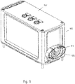
- the figure 1 shows a perspective view of a housing 103 with a housing part 100.
- the housing part 100 is designed as part of a housing 103 for electrical components.
- the housing part 100 includes a first connection device 105 which is designed as an interface to the electrical components inside the housing 103 .
- the connection device 105 is arranged directly at an opening 113, which was provided, for example, by removing a knockout area.
- the first connection device 105 and the housing part 100 it is also possible for the first connection device 105 and the housing part 100 to be designed in one piece as an integral component.
- the first connecting device 105 it would also be conceivable for the first connecting device 105 to be screwed to the housing part 100 and thus to be arranged so that it can be easily replaced.
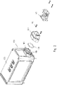
- the figure 2 shows a further perspective view of a housing 103 with a housing part 100.
- the housing part 100 is also designed as part of the housing 103 for electrical components and includes the first connection device 105 as an interface to the electrical components within the housing 103.
- the housing part 100 includes a Adapter flange 107, which is designed to be arranged on the connection device 105 and as an interface to the electrical components within the housing 103.
- the adapter flange 107 is designed as an attachment housing for a plug connector 117 and is fastened to the housing part 100 by means of a fixing means 111 .
- the fixing means 111 in this case comprises two screws, which can alternatively be designed, for example, as a manually operable clamping device.
- a sealing element 109 in the form of an O-ring is arranged between the first connecting device 105 and the adapter flange 107 . This improves the tightness of the housing part 100 considerably.
- the figure 3 shows a further perspective view of a housing 103 with a housing part 100.
- the housing part 100 is again part of a housing 103 for electrical components and includes the first connection device 105, which is designed as an interface to the electrical components within the housing 103.
- the adapter flange 107 is designed as an attachment housing for a plug connector 117 .
- the housing part 100 includes a second connection device 106. It is equipped with a further adapter flange 107 and has an internal thread.
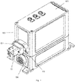
- the figure 4 shows a schematic sectional view of a housing 103 with a housing part 100.
- the housing part 100 is again part of a housing 103 and includes the first connection device 105.
- the adapter flange 107 is designed as an attachment housing for a connector 117.
- the housing 103 includes a second connection device 106. It is arranged on the housing 103 on the opposite side of the first connection device 105.
- the sealing element 109 in the form of an O-ring is arranged between the first connecting device 105 and the adapter flange 107 .
- connection devices 105 or adapter flanges 107 show different perspective views of connection devices 105 or adapter flanges 107. Due to the required flexibility of the interface, the adapter flange 107 is designed to be exchangeable.
- the Figure 5A shows a perspective view of a first connection device 105 as it is formed on the housing part 100 of a housing 103 of electrical components.
- the Figure 5B shows a perspective view of an adapter flange 107 in the form of a HanQ5 connector, as can be arranged on the first connecting device 105.
- FIG. 5C shows a further perspective view of an adapter flange 107 in the form of a HanQ8 connector, as can be arranged on the first connection device 105.
- FIG. 5D shows a further perspective view of an adapter flange 107, which is designed to completely close the first connection device 105.
- the Figure 5E shows another perspective view of an adapter flange 107, which includes a threaded socket for screw connections.
- the internal thread of the threaded base can be designed to accommodate screw connections of size M16, M20 or M25.
- the Figure 5F shows a representation of a first connection device 105, as it is formed on the housing part 100 of a housing 103 of electrical components, in a plan view.
- the figure 6 shows a further perspective view of a housing 103 with a housing part 100.
- the housing part 100 is again part of the housing 103 for electrical components and includes the first connection device 105, which is designed as an interface to the electrical components within the housing 103.
- the housing part 100 includes a second connection device 106.
- the first connection device 105 and the second connection device 106 are both arranged in parallel on the housing part 100.
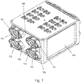
- the figure 7 shows a further perspective view of a housing 103 with a housing part 100.
- the housing part 100 is part of the housing 103 for electrical components and includes the first connection device 105 as an interface to the electrical components within the housing 103.
- the housing part 100 includes a second connection device 106 , a third connection device 114 and a fourth Connection device 115. All connection devices are arranged in parallel on the housing part 100.
Landscapes
- Engineering & Computer Science (AREA)
- Microelectronics & Electronic Packaging (AREA)
- Casings For Electric Apparatus (AREA)
- Connector Housings Or Holding Contact Members (AREA)
Description
- Die Erfindung betrifft ein Gehäuseteil für ein Gehäuse elektrischer Bauteile mit einer Anschlussvorrichtung, welche als Schnittstelle zu elektrischen Bauteilen innerhalb des Gehäuses ausgebildet ist.
- Derartige Gehäuseteile oder Gehäuseausführungen elektrischer Bauteile umfassen meist mehrere feste Schnittstellen, welche für unterschiedliche Verschraubungen oder Leitungsdurchdringungen in das Gehäuse hinein oder aus dem Gehäuse heraus ausgebildet sind. Hierbei werden oft Universalgehäuse oder Gehäuseober- und Gehäuseunterschalen in Kombination mit zusätzlichen Anschlussverbindungen genutzt, um eine applikationsspezifische Varianz an den Schnittstellen zu ermöglichen. Hierbei wird jeweils eine gewünschte Schnittstelle durch Anordnen der entsprechenden geometrischen Anschlußkontur an eine dafür vorgesehene Stelle der Gehäuseschale bereitgestellt. Nachteilig ist bei diesem Prinzip jedoch, dass bei der Herstellung der Gehäuseteile viele verschiedene Werkzeugeinsätze für alle Ausführungsvarianten erforderlich sind.
- Die Druckschrift
US 2015/0044903 A1 beschreibt eine Abdeckplatte, die Teil eines Gehäuses eines elektronischen Gerätes bzw. einer Steuereinheit ist. - Die Druckschrift
WO 2008/055597 A1 beschreibt eine Adaptervorrichtung für einen Spannungswandler für Mobilgeräte. - Die Druckschrift
DE 299 22 206 U1 beschreibt ein Stecker-Kupplungssystem zum Anschluss eines von einem Gehäuse umgebenen elektrischen Bauteils, insbesondere eines Sensors. - Die Druckschrift
DE 36 25 500 A1 beschreibt ein Frontsteckeranschlusssystem, bei dem in die Kontaktklammern eines Frontsteckergehäuses Verbindungselemente mit unterschiedlichen Anschlusstechniken eingebettet und arretiert werden können. -
CN 202 797 468 U ist ein Gebrauchsmuster, das einen Netzteiladapter offenbart, der Stecker ersetzen kann. - Es ist die Aufgabe der vorliegenden Erfindung ein verbessertes Konzept für ein Gehäuseteil mit einer universellen Schnittstelle bereitzustellen.
- Diese Aufgabe wird durch den Gegenstand mit den Merkmalen nach den unabhängigen Ansprüchen gelöst. Vorteilhafte Ausführungsformen der Erfindung sind Gegenstand der Figuren, der Beschreibung und der abhängigen Ansprüche.
- Gemäß einem Aspekt der Erfindung wird die Aufgabe durch ein Gehäuseteil für ein Gehäuse elektrischer Bauteile mit einer ersten universellen Anschlussvorrichtung, welche als Schnittstelle zu elektrischen Bauteilen innerhalb des Gehäuses ausgebildet ist, und einem anwendungsspezifischen Adapterflansch gelöst, welcher zum Anordnen an die erste Anschlussvorrichtung und als Schnittstelle zu den elektrischen Bauteilen innerhalb des Gehäuses ausgebildet ist. Dadurch wird beispielsweise der technische Vorteil erreicht, dass mit einer universellen Anschlussvorrichtung in Verbindung mit einem anwendungsspezifischen Adapterflansch aus einer Vielzahl von unterschiedlichen Adapterflanschen an einer einzigen Position eines Gehäuses für elektrische Bauteile jede gewünschte Schnittstelle hergestellt werden kann. Hierbei ist es besonders vorteilhaft, dass die Herstellung der entsprechenden Gehäuseteile mit einer einzigen universellen Schnittstelle preiswert und unter Einsatz weniger Werkzeugeinsätze möglich ist. Somit können die Gehäuseteile oder die Gehäuseteile werkzeugunabhängig den Anwendungsanforderungen entsprechend konfektioniert werden.
- Um die Flexibilität der universellen Schnittstelle besonders stark auszubilden, ist der Adapterflansch austauschbar ausgebildet. Somit ist es möglich, an die erste Anschlussvorrichtung einen bevorzugten Adapterflansch anzuordnen, der dem jeweiligen Zweck einer Anwendung entspricht. Zusätzlich ist durch die Austauschbarkeit des Adapterflansches möglich, durch einen Wechsel des Adapterflansches den Zweck oder die Anwendung zu variieren.
- Gemäß einer bevorzugten Ausführungsform, umfasst der Adapterflansch einen Anschraubsockel für Verschraubungen. Dadurch wird beispielsweise der technische Vorteil erreicht, dass eine sehr einfache und flexible Form der Anordnung des Adapterflanschs an der ersten Anschlussvorrichtung möglich ist.
- Gemäß einer weiteren bevorzugten Ausführungsform, ist der Adapterflansch dazu ausgebildet, metrische Anschlussverschraubungen aufzunehmen. Beispielsweise können hier Verschraubungen der Größe M16, M20 oder M25 eingesetzt werden. Dadurch wird beispielsweise der technische Vorteil erreicht, dass die Verschraubungen mit bestehenden Werkzeugeinsätzen besonders einfach herstellbar sind. Somit kann für die Herstellung auf bestehende Mittel zurückgegriffen werden. Jedoch ist es hier ebenso denkbar, die Verschraubung mit anderen Größen oder Formaten zu versehen.
- Um die Anordnung des Adapterflanschs besonders zuverlässig zu gestalten, ist der Adapterflansch als Anbaugehäuse für einen Steckverbinder ausgebildet. Besonders geeignet sind hier beispielsweise Industriesteckverbinder HC-Q5 oder HC-Q8. Derartige Steckverbinder sind zudem besonders robust gegenüber Feuchtigkeit, Hitze oder gegebenenfalls auftretenden Umwelteinflüssen.
- Gemäß einer weiteren besonders bevorzugten Ausführungsform, ist der Adapterflansch dazu ausgebildet die erste Anschlussvorrichtung vollständig zu verschließen. Dadurch wird beispielsweise der technische Vorteil erreicht, dass ein elektrische Bauteile tragendes Gehäuse bedarfsweise vollständig verschlossen werden kann. Dies kann beispielsweise während der Montage des Gehäuses oder bei einem Austausch eines derartigen Gehäuses der Fall sein. Ferner kann ein derartiges Gehäuse für einen Transport zuverlässig verschlossen werden, wodurch die elektrischen Bauteile im Innenraum vor Feuchtigkeit geschützt werden können.
- Um die Zuverlässigkeit und die Dichtheit der Verbindung zwischen der ersten Anschlussvorrichtung und dem Adapterflansch zu verbessern und insbesondere um das Eindringen von Feuchtigkeit zu verhindern, weist das Gehäuseteil ein Dichtelement auf um die erste Anschlussvorrichtung und den Adapterflansch gegeneinander abzudichten.
- Gemäß einer bevorzugten Ausführungsform, ist das Dichtelement als O-Ring ausgebildet und zwischen der ersten Anschlussvorrichtung und dem Adapterflansch angeordnet. Derartige O-Ringe sind preiswert in der Herstellung und effektiv in ihrer Wirkung.
- Um den Adapterflansch besonders zuverlässig und stabil zu fixieren, umfasst der Adapterflansch Fixiermittel, um den Adapterflansch an dem Gehäuseteil zu befestigen. Besonders einfach und effektiv eignen sich hierfür Schrauben. Die Schrauben können hierbei eine Verbindung zwischen dem Adapterflansch und der ersten Anschlussvorrichtung herstellen, jedoch wäre es ebenso denkbar, dass die Schrauben den Adapterflansch direkt mit dem Gehäuseteil oder dem Gehäuse verbinden.
- In einer bevorzugten Ausführungsform, ist das Fixiermittel als manuell betätigbare Klemmvorrichtung ausgebildet. Dadurch wird beispielsweise der technische Vorteil erreicht, dass ein Wechsel des Adapterflanschs sehr schnell und ohne den Einsatz von Werkzeug möglich ist.
- In einer noch weiteren bevorzugten Ausführungsform, sind die erste Anschlussvorrichtung und das Gehäuseteil einstückig als integrales Bauteil ausgebildet. Dies vereinfacht die Herstellung und die Herstellungskosten des Gehäuseteils erheblich, da weniger Einzelbauteil hergestellt und montiert werden müssen.
- Gemäß einer noch weiteren bevorzugten Ausführungsform, ist die erste Anschlussvorrichtung an dem Gehäuseteil verschraubbar angeordnet. Dadurch wird beispielsweise der technische Vorteil erreicht, dass die erste Anschlussvorrichtung sehr einfach an Gehäuseteilen angeordnet werden kann. Zusätzlich kann die erste Anschlussvorrichtung von dem Gehäuseteil entfernt und ausgewechselt werden.
- Um die Flexibilität und das Einsatzspektrum des Gehäuseteils zu erhöhen, weist das Gehäuseteil zumindest eine zweite Anschlussvorrichtung und einen weiteren Adapterflansch auf. Hierbei kann die zweite Anschlussvorrichtung mit dem identischen Adapterflansch verbunden werden. Ebenso ist jedoch denkbar, die erste Anschlussvorrichtung und die zweite Anschlussvorrichtung mit jeweils unterschiedlichen Adapterflanschen auszustatten. Hierbei können die unterschiedlichen Schnittstellen bedarfsgerecht auch an verschiedene Gehäuseteile eines Gehäuses für elektrische Bauteile angeordnet sein.
- In einer weiteren bevorzugten Ausführungsform, ist die Anschlussvorrichtung dazu ausgebildet den Adapterflansch formschlüssig zu übergreifen. Dadurch wird der technische Vorteil erreicht, dass die innenliegende Dichtung geschützt wird und die Verbindung verschmutzungsunempfindlich und mechanisch hoch belastbar ausgeführt ist.
- Um die Handhabung des Adapterflanschs und der Anschlussvorrichtung einfach und kostengünstig in Herstellung und Installation zu realisieren, sind der Adapterflansch und die Anschlussvorrichtung miteinander verrastbar ausgebildet.
- Gemäß einem weiteren Aspekt der Erfindung wird die Aufgabe durch ein Verfahren zum Herstellen eines Gehäuseteils für ein Gehäuse elektrischer Bauteile mit den Schritten
- Bereitstellen eines Gehäuseteils für ein Gehäuse mit einer Anschlussvorrichtung, welche als Schnittstelle zu elektrischen Bauteilen innerhalb eines Gehäuses ausgebildet ist, und Anordnen eines bestimmten Adapterflanschs aus einer Vielzahl von Adapterflanschen an die Anschlussvorrichtung, um eine bevorzugte Schnittstelle zu den elektrischen Bauteilen innerhalb eines Gehäuses herzustellen, gelöst. Dadurch wird beispielsweise der technische Vorteil erreicht, dass mit der universellen Anschlussvorrichtung in Verbindung mit einem bestimmten Adapterflansch aus einer Vielzahl von unterschiedlichen Adapterflanschen an einer einzigen Position eines Gehäuses für elektrische Bauteile jede gewünschte Schnittstelle hergestellt werden kann. Hierbei ist es besonders vorteilhaft, dass die Herstellung der entsprechenden Gehäuseteile mit einer einzigen universellen Schnittstelle preiswert und unter Einsatz weniger Werkzeugeinsätze möglich ist. Somit können die Gehäuseteile oder die Gehäuseteile werkzeugunabhängig konfektioniert werden.
- Weitere Ausführungsbeispiele der Erfindung sind in den Zeichnungen dargestellt und werden im Folgenden näher beschrieben.
- Es zeigen:
- Fig. 1
- eine perspektivische Darstellung eines Gehäuses mit einem Gehäuseteil,
- Fig. 2
- eine weitere perspektivische Darstellung eines Gehäuses mit einem Gehäuseteil,
- Fig. 3
- eine weitere perspektivische Darstellung eines Gehäuses mit einem Gehäuseteil,
- Fig. 4
- eine schematische Schnittdarstellung eines Gehäuses mit einem Gehäuseteil,
- Fig. 5A
- eine perspektivische Darstellung einer Anschlussvorrichtung,
- Fig. 5B
- eine perspektivische Darstellung eines Adapterflanschs,
- Fig. 5C
- eine weitere perspektivische Darstellung eines Adapterflanschs,
- Fig. 5D
- eine weitere perspektivische Darstellung eines Adapterflanschs,
- Fig. 5E
- eine weitere perspektivische Darstellung eines Adapterflanschs,
- Fig. 5F
- eine weitere Darstellung einer Anschlussvorrichtung,
- Fig. 6
- eine weitere perspektivische Darstellung eines Gehäuses mit einem Gehäuseteil, und
- Fig. 7
- eine weitere perspektivische Darstellung eines Gehäuses mit einem Gehäuseteil.
- Die
Figur 1 zeigt eine perspektivische Darstellung eines Gehäuses 103 mit einem Gehäuseteil 100. Das Gehäuseteil 100 ist als Teil eines Gehäuses 103 für elektrische Bauteile ausgebildet. Das Gehäuseteil 100 umfasst eine erste Anschlussvorrichtung 105, welche als Schnittstelle zu den elektrischen Bauteilen innerhalb des Gehäuses 103 ausgebildet ist. Hierbei ist die Anschlussvorrichtung 105 unmittelbar an einer Öffnung 113 angeordnet, welche beispielsweise durch Entfernen eines Knockout-Bereichs bereitgestellt wurde. Alternativ ist es jedoch ebenso möglich, dass die erste Anschlussvorrichtung 105 und das Gehäuseteil 100 einstückig als integrales Bauteil ausgebildet sind. In bestimmten Anwendungen wäre auch denkbar, die erste Anschlussvorrichtung 105 an dem Gehäuseteil 100 verschraubbar und damit leicht auswechselbar anzuordnen. - Die
Figur 2 zeigt eine weitere perspektivische Darstellung eines Gehäuses 103 mit einem Gehäuseteil 100. Das Gehäuseteil 100 ist ebenso als Teil des Gehäuses 103 für elektrische Bauteile ausgebildet und umfasst die erste Anschlussvorrichtung 105 als Schnittstelle zu den elektrischen Bauteilen innerhalb des Gehäuses 103. Zusätzlich umfasst das Gehäuseteil 100 einen Adapterflansch 107, welcher zum Anordnen an die Anschlussvorrichtung 105 und als Schnittstelle zu den elektrischen Bauteilen innerhalb des Gehäuses 103 ausgebildet ist. - Der Adapterflansch 107 ist als Anbaugehäuse für einen Steckverbinder 117 ausgebildet und mittels eines Fixiermittels 111 an dem Gehäuseteil 100 befestigt. Das Fixiermittel 111 umfasst hierbei zwei Schrauben, welches alternativ beispielsweise als manuell betätigbare Klemmvorrichtung ausgebildet sein kann. Zwischen der ersten Anschlussvorrichtung 105 und dem Adapterflansch 107 ist ein Dichtelement 109 in Form eines O-Rings angeordnet. Dies verbessert die Dichtheit des Gehäuseteils 100 erheblich.
- Die
Figur 3 zeigt eine weitere perspektivische Darstellung eines Gehäuses 103 mit einem Gehäuseteil 100. Das Gehäuseteil 100 ist erneut Teil eines Gehäuses 103 für elektrische Bauteile und umfasst die erste Anschlussvorrichtung 105, welche als Schnittstelle zu den elektrischen Bauteilen innerhalb des Gehäuses 103 ausgebildet ist. Der Adapterflansch 107 ist als Anbaugehäuse für einen Steckverbinder 117 ausgebildet. Zusätzlich umfasst das Gehäuseteil 100 eine zweite Anschlussvorrichtung 106. Sie ist mit einem weiteren Adapterflansch 107 ausgestattet und weist ein Innengewinde auf. - Die
Figur 4 zeigt eine schematische Schnittdarstellung eines Gehäuses 103 mit einem Gehäuseteil 100. Das Gehäuseteil 100 ist erneut Teil eines Gehäuses 103 und umfasst die erste Anschlussvorrichtung 105. Der Adapterflansch 107 ist als Anbaugehäuse für einen Steckverbinder 117 ausgebildet. Zusätzlich umfasst das Gehäuse 103 eine zweite Anschlussvorrichtung 106. Sie ist an dem Gehäuse 103 auf der gegenüberliegenden Seite der ersten Anschlussvorrichtung 105 angeordnet. Zwischen der ersten Anschlussvorrichtung 105 und dem Adapterflansch 107 ist das Dichtelement 109 in Form eines O-Rings angeordnet. - Die
Figuren 5A bis 5F zeigen unterschiedliche perspektivische Darstellungen von Anschlussvorrichtungen 105 oder Adapterflanschen 107. Aufgrund der geforderten Flexibilität der Schnittstelle ist der Adapterflansch 107 austauschbar ausgebildet. - Die
Figur 5A zeigt eine perspektivische Darstellung einer ersten Anschlussvorrichtung 105, wie sie an dem Gehäuseteil 100 eines Gehäuses 103 elektrischer Bauteile ausgebildet ist. - Die
Figur 5B zeigt eine perspektivische Darstellung eines Adapterflanschs 107 in Form eines HanQ5 - Steckverbinders, wie er an der ersten Anschlussvorrichtung 105 angeordnet werden kann. - Die
Figur 5C zeigt eine weitere perspektivische Darstellung eines Adapterflanschs 107 in Form eines HanQ8 - Steckverbinders, wie er an der ersten Anschlussvorrichtung 105 angeordnet werden kann. - Die
Figur 5D zeigt eine weitere perspektivische Darstellung eines Adapterflanschs 107, welcher dazu ausgebildet ist die erste Anschlussvorrichtung 105 vollständig zu verschließen. - Die
Figur 5E zeigt eine noch weitere perspektivische Darstellung eines Adapterflanschs 107, welcher einen Gewindesockel für Verschraubungen umfasst. Beispielsweise kann das Innengewinde des Gewindesockels dazu ausgebildet sein Verschraubungen der Größe M16, M20 oder M25 aufzunehmen. - Die
Figur 5F zeigt eine Darstellung einer ersten Anschlussvorrichtung 105, wie sie an dem Gehäuseteil 100 eines Gehäuses 103 elektrischer Bauteile ausgebildet ist, in einer Draufsicht. - Die
Figur 6 zeigt eine weitere perspektivische Darstellung eines Gehäuses 103 mit einem Gehäuseteil 100. Das Gehäuseteil 100 ist erneut Teil des Gehäuses 103 für elektrische Bauteile und umfasst die erste Anschlussvorrichtung 105, welche als Schnittstelle zu den elektrischen Bauteilen innerhalb des Gehäuses 103 ausgebildet ist. Zusätzlich umfasst das Gehäuseteil 100 eine zweite Anschlussvorrichtung 106. Die erste Anschlussvorrichtung 105 und die zweite Anschlussvorrichtung 106 sind beide parallel an dem Gehäuseteil 100 angeordnet. - Die
Figur 7 zeigt eine weitere perspektivische Darstellung eines Gehäuses 103 mit einem Gehäuseteil 100. Das Gehäuseteil 100 ist Teil des Gehäuses 103 für elektrische Bauteile und umfasst die erste Anschlussvorrichtung 105 als Schnittstelle zu den elektrischen Bauteilen innerhalb des Gehäuses 103. Zusätzlich umfasst das Gehäuseteil 100 eine zweite Anschlussvorrichtung 106, eine dritte Anschlussvorrichtung 114 und eine vierte Anschlussvorrichtung 115. Alle Anschlussvorrichtungen sind parallel an dem Gehäuseteil 100 angeordnet. - Alle in Verbindung mit einzelnen Ausführungsformen der Erfindung erläuterten und gezeigten Merkmale können in unterschiedlicher Kombination in dem erfindungsgemäßen Gegenstand vorgesehen sein, um gleichzeitig deren vorteilhafte Wirkungen zu realisieren.
-
- 100
- Gehäuseteil
- 103
- Gehäuse
- 105
- Erste Anschlussvorrichtung
- 106
- Zweite Anschlussvorrichtung
- 107
- Adapterflansch
- 109
- Dichtelement
- 111
- Fixiermittel
- 113
- Öffnung
- 114
- Dritte Anschlussvorrichtung
- 115
- Vierte Anschlussvorrichtung
- 117
- Steckverbinder
Claims (14)
- Gehäuseteil (100) für ein Gehäuse (103) elektrischer Bauteile, mit:einer ersten universellen Anschlussvorrichtung (105), welche als Schnittstelle zu elektrischen Bauteilen innerhalb des Gehäuses (103) ausgebildet ist, undeinem anwendungsspezifischen Adapterflansch (107), welcher zum Anordnen an die erste Anschlussvorrichtung (105) und als Schnittstelle zu den elektrischen Bauteilen innerhalb des Gehäuses (103) ausgebildet ist,wobei der Adapterflansch (107) einen Anschraubsockel für Verschraubungen umfasst.
- Gehäuseteil (100) nach Anspruch 1, dadurch gekennzeichnet, dass der Adapterflansch (107) austauschbar ausgebildet ist.
- Gehäuseteil (100) nach Anspruch 1 oder 2, dadurch gekennzeichnet, dass der Adapterflansch (107) dazu ausgebildet ist, metrische Anschlussverschraubungen aufzunehmen.
- Gehäuseteil (100) nach Anspruch 1 oder 2, dadurch gekennzeichnet, dass der Adapterflansch (107) als Anbaugehäuse für einen Steckverbinder ausgebildet ist.
- Gehäuseteil (100) nach einem der vorangehenden Ansprüche, dadurch gekennzeichnet, dass der Adapterflansch (107) dazu ausgebildet ist die erste Anschlussvorrichtung (105) vollständig zu verschließen.
- Gehäuseteil (100) nach einem der vorangehenden Ansprüche, dadurch gekennzeichnet, dass das Gehäuseteil (100) ein Dichtelement (109) aufweist, um die erste Anschlussvorrichtung (105) und den Adapterflansch (107) gegeneinander abzudichten.
- Gehäuseteil (100) nach einem der vorangehenden Ansprüche, dadurch gekennzeichnet, dass der Adapterflansch (107) Fixiermittel (111) umfasst, um den Adapterflansch (107) an dem Gehäuseteil (100) zu befestigen.
- Gehäuseteil (100) nach Anspruch 7, dadurch gekennzeichnet, dass das Fixiermittel (111) als manuell betätigbare Klemmvorrichtung ausgebildet ist
- Gehäuseteil (100) nach einem der vorangehenden Ansprüche, dadurch gekennzeichnet, dass die erste Anschlussvorrichtung (105) und das Gehäuseteil (100) einstückig als integrales Bauteil ausgebildet sind.
- Gehäuseteil (100) nach einem der Ansprüche 1 bis 8, dadurch gekennzeichnet, dass die erste Anschlussvorrichtung (105) an dem Gehäuseteil (100) verschraubbar angeordnet ist.
- Gehäuseteil (100) nach einem der vorangehenden Ansprüche, dadurch gekennzeichnet, dass die erste Anschlussvorrichtung (105) dazu ausgebildet ist, den Adapterflansch (107) formschlüssig zu übergreifen.
- Gehäuseteil (100) nach einem der vorangehenden Ansprüche, dadurch gekennzeichnet, dass der Adapterflansch (107) und die erste Anschlussvorrichtung (105) miteinander verrastbar ausgebildet sind.
- Gehäuseteil (100) nach einem der vorangehenden Ansprüche, dadurch gekennzeichnet, dass das Gehäuseteil (100) zumindest eine zweite Anschlussvorrichtung (106) und einen weiteren Adapterflansch (107) aufweist.
- Verfahren zum Herstellen eines Gehäuseteils (100) für ein Gehäuse (103) elektrischer Bauteile nach einen der Ansprüche 1 bis 13, mit den Schritten:Bereitstellen eines Gehäuseteils (100) für ein Gehäuse mit einer Anschlussvorrichtung (105), welche als Schnittstelle zu elektrischen Bauteilen innerhalb eines Gehäuses (103) ausgebildet ist,Anordnen eines bestimmten Adapterflanschs (107) aus einer Vielzahl von Adapterflanschen an die Anschlussvorrichtung (105) um eine bevorzugte Schnittstelle zu den elektrischen Bauteilen innerhalb eines Gehäuses (103) herzustellen.
Applications Claiming Priority (2)
| Application Number | Priority Date | Filing Date | Title |
|---|---|---|---|
| DE102016123759.0A DE102016123759A1 (de) | 2016-12-08 | 2016-12-08 | Gehäuseteil für ein gehäuse elektrischer bauteile |
| PCT/EP2017/081266 WO2018104184A1 (de) | 2016-12-08 | 2017-12-01 | Gehäuseteil für ein gehäuse elektrischer bauteile |
Publications (2)
| Publication Number | Publication Date |
|---|---|
| EP3552466A1 EP3552466A1 (de) | 2019-10-16 |
| EP3552466B1 true EP3552466B1 (de) | 2022-05-18 |
Family
ID=60574588
Family Applications (1)
| Application Number | Title | Priority Date | Filing Date |
|---|---|---|---|
| EP17808888.6A Not-in-force EP3552466B1 (de) | 2016-12-08 | 2017-12-01 | Gehäuseteil für ein gehäuse elektrischer bauteile |
Country Status (5)
| Country | Link |
|---|---|
| US (1) | US20200068734A1 (de) |
| EP (1) | EP3552466B1 (de) |
| CN (1) | CN110050517A (de) |
| DE (1) | DE102016123759A1 (de) |
| WO (1) | WO2018104184A1 (de) |
Citations (1)
| Publication number | Priority date | Publication date | Assignee | Title |
|---|---|---|---|---|
| CN202797468U (zh) * | 2012-08-17 | 2013-03-13 | 深圳市福瑞康电子有限公司 | 一种可换插头的电源适配器 |
Family Cites Families (6)
| Publication number | Priority date | Publication date | Assignee | Title |
|---|---|---|---|---|
| DE3625500A1 (de) | 1986-07-28 | 1988-02-18 | Kloeckner Moeller Elektrizit | Frontsteckeranschlusssystem |
| DE29922206U1 (de) | 1999-12-17 | 2000-03-09 | SIE Sensorik Industrie-Elektronik GmbH, 68519 Viernheim | Stecker-Kupplung-System zum Anschluß eines elektrischen Bauteils |
| ES2320611B1 (es) * | 2006-11-06 | 2010-01-12 | Inoitulos, S.L. | "dispositivo adaptador para la carga de aparatos electronicos portatiles". |
| DE102012204145A1 (de) * | 2012-03-16 | 2013-09-19 | Continental Automotive Gmbh | Gehäuseblende zur Aufnahme von Steckermodulen |
| CN205039365U (zh) * | 2015-09-22 | 2016-02-17 | 北京新能源汽车股份有限公司 | 用于电动车的连接器和电动车 |
| CN105826747A (zh) * | 2016-05-09 | 2016-08-03 | 深圳黑鱼文化科技有限公司 | 一种多功能电子产品组合构造 |
-
2016
- 2016-12-08 DE DE102016123759.0A patent/DE102016123759A1/de not_active Ceased
-
2017
- 2017-12-01 WO PCT/EP2017/081266 patent/WO2018104184A1/de not_active Ceased
- 2017-12-01 EP EP17808888.6A patent/EP3552466B1/de not_active Not-in-force
- 2017-12-01 US US16/466,384 patent/US20200068734A1/en not_active Abandoned
- 2017-12-01 CN CN201780075521.5A patent/CN110050517A/zh active Pending
Patent Citations (1)
| Publication number | Priority date | Publication date | Assignee | Title |
|---|---|---|---|---|
| CN202797468U (zh) * | 2012-08-17 | 2013-03-13 | 深圳市福瑞康电子有限公司 | 一种可换插头的电源适配器 |
Also Published As
| Publication number | Publication date |
|---|---|
| US20200068734A1 (en) | 2020-02-27 |
| CN110050517A (zh) | 2019-07-23 |
| DE102016123759A1 (de) | 2018-06-14 |
| WO2018104184A1 (de) | 2018-06-14 |
| EP3552466A1 (de) | 2019-10-16 |
Similar Documents
| Publication | Publication Date | Title |
|---|---|---|
| EP3494621B1 (de) | Vorrichtung und verfahren zur kabeldurchführung durch einen wanddurchbruch | |
| EP3292601B1 (de) | Kabel-/leitungseinführung | |
| EP3132506B1 (de) | Kabelabgang | |
| EP3292603B1 (de) | Kabel-/leitungseinführung | |
| EP1891710A1 (de) | Elektrische steckverbindung, steckerteil und buchsenteil | |
| EP3613110B1 (de) | Baugruppe für ein steckverbinderteil mit einem kontakteinsatz und einem erdungselement | |
| WO2020007555A1 (de) | Steckverbindungselement für ein kraftfahrzeug und verfahren zum herstellen eines solchen steckverbindungselements | |
| DE102008046932A1 (de) | Gehäuse für eine elektrische Steckverbindung | |
| EP3120442B1 (de) | Elektromotor, insbesondere aussenläufermotor, sowie zwischenisolierteil für einen elektromotor | |
| EP3842187A1 (de) | Vorrichtung zur verbindung eines netzkabels | |
| EP3586415A1 (de) | Steckerkupplung mit zugentlastung für ein verbindungskabel | |
| EP3497746B1 (de) | Dachantenne mit verrastungsdrehkreuz | |
| EP4399776B1 (de) | Anschlussteil mit doppelten stromschienen | |
| DE102017129742A1 (de) | Kompaktes Anbaugehäuse | |
| EP3522307B1 (de) | Kabelzugentlastung und schirmbefestigung bei einem steckverbindergehäuse | |
| EP3483996B1 (de) | Anordnung für eine kabeldurchführung | |
| EP3123564B1 (de) | Elektronikbox mit einer leiterplatte und einem elektrischen bauteil sowie einer kontaktierungsvorrichtung | |
| EP3552466B1 (de) | Gehäuseteil für ein gehäuse elektrischer bauteile | |
| DE202015008215U1 (de) | Kontaktierungsvorrichtung, Anschlussgehäuse, Stellantrieb und Baureihe | |
| DE102009033948A1 (de) | Kabel- oder Schlauchverschraubung | |
| EP3183787A1 (de) | Elektrisches gerät | |
| EP1673841A1 (de) | Emv-dichte haltevorrichtung für kabel | |
| EP3298866B1 (de) | Elektrische kontaktanordnung | |
| DE202019101084U1 (de) | Anschlusseinrichtung | |
| DE102006036097B3 (de) | Steckverbinder, Anordnung mit Steckverbinder und Verfahren zur Montage |
Legal Events
| Date | Code | Title | Description |
|---|---|---|---|
| STAA | Information on the status of an ep patent application or granted ep patent |
Free format text: STATUS: UNKNOWN |
|
| STAA | Information on the status of an ep patent application or granted ep patent |
Free format text: STATUS: THE INTERNATIONAL PUBLICATION HAS BEEN MADE |
|
| PUAI | Public reference made under article 153(3) epc to a published international application that has entered the european phase |
Free format text: ORIGINAL CODE: 0009012 |
|
| STAA | Information on the status of an ep patent application or granted ep patent |
Free format text: STATUS: REQUEST FOR EXAMINATION WAS MADE |
|
| 17P | Request for examination filed |
Effective date: 20190614 |
|
| AK | Designated contracting states |
Kind code of ref document: A1 Designated state(s): AL AT BE BG CH CY CZ DE DK EE ES FI FR GB GR HR HU IE IS IT LI LT LU LV MC MK MT NL NO PL PT RO RS SE SI SK SM TR |
|
| AX | Request for extension of the european patent |
Extension state: BA ME |
|
| DAV | Request for validation of the european patent (deleted) | ||
| DAX | Request for extension of the european patent (deleted) | ||
| STAA | Information on the status of an ep patent application or granted ep patent |
Free format text: STATUS: EXAMINATION IS IN PROGRESS |
|
| 17Q | First examination report despatched |
Effective date: 20210512 |
|
| GRAP | Despatch of communication of intention to grant a patent |
Free format text: ORIGINAL CODE: EPIDOSNIGR1 |
|
| STAA | Information on the status of an ep patent application or granted ep patent |
Free format text: STATUS: GRANT OF PATENT IS INTENDED |
|
| INTG | Intention to grant announced |
Effective date: 20220105 |
|
| GRAS | Grant fee paid |
Free format text: ORIGINAL CODE: EPIDOSNIGR3 |
|
| GRAF | Information related to payment of grant fee modified |
Free format text: ORIGINAL CODE: EPIDOSCIGR3 |
|
| GRAA | (expected) grant |
Free format text: ORIGINAL CODE: 0009210 |
|
| STAA | Information on the status of an ep patent application or granted ep patent |
Free format text: STATUS: THE PATENT HAS BEEN GRANTED |
|
| AK | Designated contracting states |
Kind code of ref document: B1 Designated state(s): AL AT BE BG CH CY CZ DE DK EE ES FI FR GB GR HR HU IE IS IT LI LT LU LV MC MK MT NL NO PL PT RO RS SE SI SK SM TR |
|
| REG | Reference to a national code |
Ref country code: GB Ref legal event code: FG4D Free format text: NOT ENGLISH |
|
| REG | Reference to a national code |
Ref country code: CH Ref legal event code: EP |
|
| REG | Reference to a national code |
Ref country code: IE Ref legal event code: FG4D Free format text: LANGUAGE OF EP DOCUMENT: GERMAN |
|
| REG | Reference to a national code |
Ref country code: DE Ref legal event code: R096 Ref document number: 502017013220 Country of ref document: DE |
|
| REG | Reference to a national code |
Ref country code: AT Ref legal event code: REF Ref document number: 1493882 Country of ref document: AT Kind code of ref document: T Effective date: 20220615 |
|
| REG | Reference to a national code |
Ref country code: LT Ref legal event code: MG9D |
|
| REG | Reference to a national code |
Ref country code: NL Ref legal event code: MP Effective date: 20220518 |
|
| PG25 | Lapsed in a contracting state [announced via postgrant information from national office to epo] |
Ref country code: SE Free format text: LAPSE BECAUSE OF FAILURE TO SUBMIT A TRANSLATION OF THE DESCRIPTION OR TO PAY THE FEE WITHIN THE PRESCRIBED TIME-LIMIT Effective date: 20220518 Ref country code: PT Free format text: LAPSE BECAUSE OF FAILURE TO SUBMIT A TRANSLATION OF THE DESCRIPTION OR TO PAY THE FEE WITHIN THE PRESCRIBED TIME-LIMIT Effective date: 20220919 Ref country code: NO Free format text: LAPSE BECAUSE OF FAILURE TO SUBMIT A TRANSLATION OF THE DESCRIPTION OR TO PAY THE FEE WITHIN THE PRESCRIBED TIME-LIMIT Effective date: 20220818 Ref country code: NL Free format text: LAPSE BECAUSE OF FAILURE TO SUBMIT A TRANSLATION OF THE DESCRIPTION OR TO PAY THE FEE WITHIN THE PRESCRIBED TIME-LIMIT Effective date: 20220518 Ref country code: LT Free format text: LAPSE BECAUSE OF FAILURE TO SUBMIT A TRANSLATION OF THE DESCRIPTION OR TO PAY THE FEE WITHIN THE PRESCRIBED TIME-LIMIT Effective date: 20220518 Ref country code: HR Free format text: LAPSE BECAUSE OF FAILURE TO SUBMIT A TRANSLATION OF THE DESCRIPTION OR TO PAY THE FEE WITHIN THE PRESCRIBED TIME-LIMIT Effective date: 20220518 Ref country code: GR Free format text: LAPSE BECAUSE OF FAILURE TO SUBMIT A TRANSLATION OF THE DESCRIPTION OR TO PAY THE FEE WITHIN THE PRESCRIBED TIME-LIMIT Effective date: 20220819 Ref country code: FI Free format text: LAPSE BECAUSE OF FAILURE TO SUBMIT A TRANSLATION OF THE DESCRIPTION OR TO PAY THE FEE WITHIN THE PRESCRIBED TIME-LIMIT Effective date: 20220518 Ref country code: ES Free format text: LAPSE BECAUSE OF FAILURE TO SUBMIT A TRANSLATION OF THE DESCRIPTION OR TO PAY THE FEE WITHIN THE PRESCRIBED TIME-LIMIT Effective date: 20220518 Ref country code: BG Free format text: LAPSE BECAUSE OF FAILURE TO SUBMIT A TRANSLATION OF THE DESCRIPTION OR TO PAY THE FEE WITHIN THE PRESCRIBED TIME-LIMIT Effective date: 20220818 |
|
| PG25 | Lapsed in a contracting state [announced via postgrant information from national office to epo] |
Ref country code: RS Free format text: LAPSE BECAUSE OF FAILURE TO SUBMIT A TRANSLATION OF THE DESCRIPTION OR TO PAY THE FEE WITHIN THE PRESCRIBED TIME-LIMIT Effective date: 20220518 Ref country code: PL Free format text: LAPSE BECAUSE OF FAILURE TO SUBMIT A TRANSLATION OF THE DESCRIPTION OR TO PAY THE FEE WITHIN THE PRESCRIBED TIME-LIMIT Effective date: 20220518 Ref country code: LV Free format text: LAPSE BECAUSE OF FAILURE TO SUBMIT A TRANSLATION OF THE DESCRIPTION OR TO PAY THE FEE WITHIN THE PRESCRIBED TIME-LIMIT Effective date: 20220518 Ref country code: IS Free format text: LAPSE BECAUSE OF FAILURE TO SUBMIT A TRANSLATION OF THE DESCRIPTION OR TO PAY THE FEE WITHIN THE PRESCRIBED TIME-LIMIT Effective date: 20220918 |
|
| PG25 | Lapsed in a contracting state [announced via postgrant information from national office to epo] |
Ref country code: SM Free format text: LAPSE BECAUSE OF FAILURE TO SUBMIT A TRANSLATION OF THE DESCRIPTION OR TO PAY THE FEE WITHIN THE PRESCRIBED TIME-LIMIT Effective date: 20220518 Ref country code: SK Free format text: LAPSE BECAUSE OF FAILURE TO SUBMIT A TRANSLATION OF THE DESCRIPTION OR TO PAY THE FEE WITHIN THE PRESCRIBED TIME-LIMIT Effective date: 20220518 Ref country code: RO Free format text: LAPSE BECAUSE OF FAILURE TO SUBMIT A TRANSLATION OF THE DESCRIPTION OR TO PAY THE FEE WITHIN THE PRESCRIBED TIME-LIMIT Effective date: 20220518 Ref country code: EE Free format text: LAPSE BECAUSE OF FAILURE TO SUBMIT A TRANSLATION OF THE DESCRIPTION OR TO PAY THE FEE WITHIN THE PRESCRIBED TIME-LIMIT Effective date: 20220518 Ref country code: DK Free format text: LAPSE BECAUSE OF FAILURE TO SUBMIT A TRANSLATION OF THE DESCRIPTION OR TO PAY THE FEE WITHIN THE PRESCRIBED TIME-LIMIT Effective date: 20220518 Ref country code: CZ Free format text: LAPSE BECAUSE OF FAILURE TO SUBMIT A TRANSLATION OF THE DESCRIPTION OR TO PAY THE FEE WITHIN THE PRESCRIBED TIME-LIMIT Effective date: 20220518 |
|
| REG | Reference to a national code |
Ref country code: DE Ref legal event code: R097 Ref document number: 502017013220 Country of ref document: DE |
|
| PLBE | No opposition filed within time limit |
Free format text: ORIGINAL CODE: 0009261 |
|
| STAA | Information on the status of an ep patent application or granted ep patent |
Free format text: STATUS: NO OPPOSITION FILED WITHIN TIME LIMIT |
|
| PG25 | Lapsed in a contracting state [announced via postgrant information from national office to epo] |
Ref country code: AL Free format text: LAPSE BECAUSE OF FAILURE TO SUBMIT A TRANSLATION OF THE DESCRIPTION OR TO PAY THE FEE WITHIN THE PRESCRIBED TIME-LIMIT Effective date: 20220518 |
|
| 26N | No opposition filed |
Effective date: 20230221 |
|
| PG25 | Lapsed in a contracting state [announced via postgrant information from national office to epo] |
Ref country code: SI Free format text: LAPSE BECAUSE OF FAILURE TO SUBMIT A TRANSLATION OF THE DESCRIPTION OR TO PAY THE FEE WITHIN THE PRESCRIBED TIME-LIMIT Effective date: 20220518 |
|
| P01 | Opt-out of the competence of the unified patent court (upc) registered |
Effective date: 20230424 |
|
| REG | Reference to a national code |
Ref country code: CH Ref legal event code: PL |
|
| GBPC | Gb: european patent ceased through non-payment of renewal fee |
Effective date: 20221201 |
|
| REG | Reference to a national code |
Ref country code: BE Ref legal event code: MM Effective date: 20221231 |
|
| PG25 | Lapsed in a contracting state [announced via postgrant information from national office to epo] |
Ref country code: LU Free format text: LAPSE BECAUSE OF NON-PAYMENT OF DUE FEES Effective date: 20221201 |
|
| PG25 | Lapsed in a contracting state [announced via postgrant information from national office to epo] |
Ref country code: LI Free format text: LAPSE BECAUSE OF NON-PAYMENT OF DUE FEES Effective date: 20221231 Ref country code: IE Free format text: LAPSE BECAUSE OF NON-PAYMENT OF DUE FEES Effective date: 20221201 Ref country code: GB Free format text: LAPSE BECAUSE OF NON-PAYMENT OF DUE FEES Effective date: 20221201 Ref country code: CH Free format text: LAPSE BECAUSE OF NON-PAYMENT OF DUE FEES Effective date: 20221231 |
|
| PG25 | Lapsed in a contracting state [announced via postgrant information from national office to epo] |
Ref country code: FR Free format text: LAPSE BECAUSE OF NON-PAYMENT OF DUE FEES Effective date: 20221231 Ref country code: BE Free format text: LAPSE BECAUSE OF NON-PAYMENT OF DUE FEES Effective date: 20221231 |
|
| PG25 | Lapsed in a contracting state [announced via postgrant information from national office to epo] |
Ref country code: IT Free format text: LAPSE BECAUSE OF FAILURE TO SUBMIT A TRANSLATION OF THE DESCRIPTION OR TO PAY THE FEE WITHIN THE PRESCRIBED TIME-LIMIT Effective date: 20220518 |
|
| REG | Reference to a national code |
Ref country code: AT Ref legal event code: MM01 Ref document number: 1493882 Country of ref document: AT Kind code of ref document: T Effective date: 20221201 |
|
| PG25 | Lapsed in a contracting state [announced via postgrant information from national office to epo] |
Ref country code: HU Free format text: LAPSE BECAUSE OF FAILURE TO SUBMIT A TRANSLATION OF THE DESCRIPTION OR TO PAY THE FEE WITHIN THE PRESCRIBED TIME-LIMIT; INVALID AB INITIO Effective date: 20171201 |
|
| PG25 | Lapsed in a contracting state [announced via postgrant information from national office to epo] |
Ref country code: AT Free format text: LAPSE BECAUSE OF NON-PAYMENT OF DUE FEES Effective date: 20221201 |
|
| PG25 | Lapsed in a contracting state [announced via postgrant information from national office to epo] |
Ref country code: CY Free format text: LAPSE BECAUSE OF FAILURE TO SUBMIT A TRANSLATION OF THE DESCRIPTION OR TO PAY THE FEE WITHIN THE PRESCRIBED TIME-LIMIT Effective date: 20220511 Ref country code: AT Free format text: LAPSE BECAUSE OF NON-PAYMENT OF DUE FEES Effective date: 20221201 |
|
| PGFP | Annual fee paid to national office [announced via postgrant information from national office to epo] |
Ref country code: DE Payment date: 20240228 Year of fee payment: 7 |
|
| PG25 | Lapsed in a contracting state [announced via postgrant information from national office to epo] |
Ref country code: MK Free format text: LAPSE BECAUSE OF FAILURE TO SUBMIT A TRANSLATION OF THE DESCRIPTION OR TO PAY THE FEE WITHIN THE PRESCRIBED TIME-LIMIT Effective date: 20220511 |
|
| PG25 | Lapsed in a contracting state [announced via postgrant information from national office to epo] |
Ref country code: MC Free format text: LAPSE BECAUSE OF FAILURE TO SUBMIT A TRANSLATION OF THE DESCRIPTION OR TO PAY THE FEE WITHIN THE PRESCRIBED TIME-LIMIT Effective date: 20220518 |
|
| PG25 | Lapsed in a contracting state [announced via postgrant information from national office to epo] |
Ref country code: MC Free format text: LAPSE BECAUSE OF FAILURE TO SUBMIT A TRANSLATION OF THE DESCRIPTION OR TO PAY THE FEE WITHIN THE PRESCRIBED TIME-LIMIT Effective date: 20220518 |
|
| PG25 | Lapsed in a contracting state [announced via postgrant information from national office to epo] |
Ref country code: MT Free format text: LAPSE BECAUSE OF FAILURE TO SUBMIT A TRANSLATION OF THE DESCRIPTION OR TO PAY THE FEE WITHIN THE PRESCRIBED TIME-LIMIT Effective date: 20220511 |
|
| PG25 | Lapsed in a contracting state [announced via postgrant information from national office to epo] |
Ref country code: BG Free format text: LAPSE BECAUSE OF FAILURE TO SUBMIT A TRANSLATION OF THE DESCRIPTION OR TO PAY THE FEE WITHIN THE PRESCRIBED TIME-LIMIT Effective date: 20220518 |
|
| PG25 | Lapsed in a contracting state [announced via postgrant information from national office to epo] |
Ref country code: BG Free format text: LAPSE BECAUSE OF FAILURE TO SUBMIT A TRANSLATION OF THE DESCRIPTION OR TO PAY THE FEE WITHIN THE PRESCRIBED TIME-LIMIT Effective date: 20220518 |
|
| REG | Reference to a national code |
Ref country code: DE Ref legal event code: R119 Ref document number: 502017013220 Country of ref document: DE |
|
| PG25 | Lapsed in a contracting state [announced via postgrant information from national office to epo] |
Ref country code: DE Free format text: LAPSE BECAUSE OF NON-PAYMENT OF DUE FEES Effective date: 20250701 |
|
| PG25 | Lapsed in a contracting state [announced via postgrant information from national office to epo] |
Ref country code: TR Free format text: LAPSE BECAUSE OF FAILURE TO SUBMIT A TRANSLATION OF THE DESCRIPTION OR TO PAY THE FEE WITHIN THE PRESCRIBED TIME-LIMIT Effective date: 20220518 |