EP3552311B1 - Verfahren zur synchronisierung von knotenvorrichtungen in einem koaxialnetzwerk - Google Patents
Verfahren zur synchronisierung von knotenvorrichtungen in einem koaxialnetzwerk Download PDFInfo
- Publication number
- EP3552311B1 EP3552311B1 EP17878187.8A EP17878187A EP3552311B1 EP 3552311 B1 EP3552311 B1 EP 3552311B1 EP 17878187 A EP17878187 A EP 17878187A EP 3552311 B1 EP3552311 B1 EP 3552311B1
- Authority
- EP
- European Patent Office
- Prior art keywords
- signal
- network
- node
- node device
- reference signal
- Prior art date
- Legal status (The legal status is an assumption and is not a legal conclusion. Google has not performed a legal analysis and makes no representation as to the accuracy of the status listed.)
- Active
Links
Images


Classifications
-
- H—ELECTRICITY
- H04—ELECTRIC COMMUNICATION TECHNIQUE
- H04L—TRANSMISSION OF DIGITAL INFORMATION, e.g. TELEGRAPHIC COMMUNICATION
- H04L43/00—Arrangements for monitoring or testing data switching networks
- H04L43/08—Monitoring or testing based on specific metrics, e.g. QoS, energy consumption or environmental parameters
- H04L43/0852—Delays
- H04L43/0864—Round trip delays
-
- H—ELECTRICITY
- H04—ELECTRIC COMMUNICATION TECHNIQUE
- H04J—MULTIPLEX COMMUNICATION
- H04J3/00—Time-division multiplex systems
- H04J3/02—Details
- H04J3/06—Synchronising arrangements
- H04J3/0635—Clock or time synchronisation in a network
- H04J3/0682—Clock or time synchronisation in a network by delay compensation, e.g. by compensation of propagation delay or variations thereof, by ranging
-
- H—ELECTRICITY
- H04—ELECTRIC COMMUNICATION TECHNIQUE
- H04L—TRANSMISSION OF DIGITAL INFORMATION, e.g. TELEGRAPHIC COMMUNICATION
- H04L12/00—Data switching networks
- H04L12/28—Data switching networks characterised by path configuration, e.g. LAN [Local Area Networks] or WAN [Wide Area Networks]
- H04L12/2801—Broadband local area networks
-
- H—ELECTRICITY
- H04—ELECTRIC COMMUNICATION TECHNIQUE
- H04L—TRANSMISSION OF DIGITAL INFORMATION, e.g. TELEGRAPHIC COMMUNICATION
- H04L12/00—Data switching networks
- H04L12/28—Data switching networks characterised by path configuration, e.g. LAN [Local Area Networks] or WAN [Wide Area Networks]
- H04L12/2803—Home automation networks
- H04L12/2838—Distribution of signals within a home automation network, e.g. involving splitting/multiplexing signals to/from different paths
-
- H—ELECTRICITY
- H04—ELECTRIC COMMUNICATION TECHNIQUE
- H04L—TRANSMISSION OF DIGITAL INFORMATION, e.g. TELEGRAPHIC COMMUNICATION
- H04L41/00—Arrangements for maintenance, administration or management of data switching networks, e.g. of packet switching networks
- H04L41/08—Configuration management of networks or network elements
- H04L41/0803—Configuration setting
- H04L41/0823—Configuration setting characterised by the purposes of a change of settings, e.g. optimising configuration for enhancing reliability
- H04L41/0836—Configuration setting characterised by the purposes of a change of settings, e.g. optimising configuration for enhancing reliability to enhance reliability, e.g. reduce downtime
-
- H—ELECTRICITY
- H04—ELECTRIC COMMUNICATION TECHNIQUE
- H04L—TRANSMISSION OF DIGITAL INFORMATION, e.g. TELEGRAPHIC COMMUNICATION
- H04L43/00—Arrangements for monitoring or testing data switching networks
- H04L43/08—Monitoring or testing based on specific metrics, e.g. QoS, energy consumption or environmental parameters
- H04L43/0852—Delays
- H04L43/0858—One way delays
-
- H—ELECTRICITY
- H04—ELECTRIC COMMUNICATION TECHNIQUE
- H04L—TRANSMISSION OF DIGITAL INFORMATION, e.g. TELEGRAPHIC COMMUNICATION
- H04L5/00—Arrangements affording multiple use of the transmission path
- H04L5/003—Arrangements for allocating sub-channels of the transmission path
- H04L5/0048—Allocation of pilot signals, i.e. of signals known to the receiver
-
- H—ELECTRICITY
- H04—ELECTRIC COMMUNICATION TECHNIQUE
- H04L—TRANSMISSION OF DIGITAL INFORMATION, e.g. TELEGRAPHIC COMMUNICATION
- H04L7/00—Arrangements for synchronising receiver with transmitter
- H04L7/0016—Arrangements for synchronising receiver with transmitter correction of synchronization errors
- H04L7/0033—Correction by delay
- H04L7/0041—Delay of data signal
-
- H—ELECTRICITY
- H04—ELECTRIC COMMUNICATION TECHNIQUE
- H04J—MULTIPLEX COMMUNICATION
- H04J3/00—Time-division multiplex systems
-
- H—ELECTRICITY
- H04—ELECTRIC COMMUNICATION TECHNIQUE
- H04L—TRANSMISSION OF DIGITAL INFORMATION, e.g. TELEGRAPHIC COMMUNICATION
- H04L12/00—Data switching networks
- H04L12/28—Data switching networks characterised by path configuration, e.g. LAN [Local Area Networks] or WAN [Wide Area Networks]
Definitions
- the present invention relates to improvements in the art of a data communications networks, in which data communication is provided over a coaxial network. More specifically, it relates to a method for synchronization of a data communications network including a plurality of node devices which are interconnected through a coaxial network and configured for data communication in a MoCA, Multimedia over Coaxial Alliance, access network, as claimed in the appended independent claim 1.
- Advantageous aspects are set out in the dependent claims.
- coaxial (coax in short) networks have regularly been implemented in such facilities.
- Provision of signal access to a building has been accomplished in different ways throughout the years, from the early solution with a local antenna receiver to wired cable TV connection, and later optical fiber networks. Still, there is a need to distribute access within the building, for which the local coaxial network may be used.
- a plurality of node devices may be free running devices, meaning that their local clocks are not synchronized. This means that a data communication network or system including a plurality of node devices is typically not optimized for running applications requiring very accurate synchronization.
- MoCA Multimedia over Coaxial Alliance
- MoCA technology runs over the existing in-home coaxial cabling, enabling whole-home distribution of digital content.
- MoCA provides the backbone for the home digital entertainment network, and supports streaming media such as standard television and allows linking a set-top box to a TV and other entertainment such as computers or game consoles in multiple rooms using existing wiring.
- MoCA is typically designed and used for providing data access within a home.
- a MoCA node device is required.
- the MoCA node device may be a MoCA adapter or modem, having at least a coaxial connector for connection to the coaxial network, and a network output, such as an Ethernet switch.
- the node device further includes a MoCA chip or chipset, configured to control media-sharing in accordance with one or more of the MoCA specifications, in cable-equipped households.
- US2010/098110 proposes solutions for using ranging to improve network efficiency and local clock time synchronization in a MoCA network.
- a method for synchronizing a plurality of nodes on such a communication network comprising: exchanging local clock times between a first node and a second node over the communication network; performing a ranging method between the first and second nodes based on the local clock times exchanged between the first and second nodes, wherein the ranging method results in an estimated propagation delay between the first and second nodes; and adjusting the local clock times of the first and second nodes based on the estimated propagation delay, thereby resulting in a synchronized local clock time at the first and second nodes.
- US2006198634A1 discloses an apparatus and methods for testing a passive optical network with regard to fiber connectivity and attenuation losses, and with regard to the proper operation of packet-based communication protocols thereon.
- US2010171530A1 discloses a time-to-amplitude component having an integrated designed configured to measure a time difference between a start signal and a stop signal includes a first time-to-amplitude converter having a delay chain, a resistor network, a capacitor configured to be chargeable via the resistor network, and a respective driver.
- the component further includes a control device and a stabilizing device including a control circuit for generating a regulated control voltage.
- Embodiments of the invention are described herein with reference to schematic illustrations of idealized embodiments of the invention. As such, variations from the shapes and relative sizes of the illustrations as a result, for example, of manufacturing techniques and/or tolerances, are to be expected. Thus, embodiments of the invention should not be construed as limited to the particular shapes and relative sizes of regions illustrated herein but are to include deviations in shapes and/or relative sizes that result, for example, from different operational constraints and/or from manufacturing constraints. Thus, the elements illustrated in the figures are schematic in nature and their shapes are not intended to illustrate the actual shape of a region of a device and are not intended to limit the scope of the invention.
- Embodiments provided herein serve to explain different ways of realizing a solution for improving synchronization between various node devices interconnected over a coaxial cable in a data communication network. This may be beneficial e.g. for the purpose of performing Wi-Fi based positioning or carrying out various measurement applications. For these operations to work, synchronization must be as good as possible since even a small deviation from synchronization could negatively impact the localization or measurement accuracy.
- Various embodiments presented herein are described as related to a data communication or access network system, in which a plurality of independent user entities are connected to a common coaxial network.
- an already present coaxial network in e.g. a multi-family house, a hotel etc., can be employed for providing access to an external physical broadband data channel, such as an optical fiber cable.
- the data communication network includes a plurality of node devices, connected to the same coaxial network. Of these node devices, one or more may be a network management device, which connects an external data channel to the coaxial network.
- the invention will be described herein with reference to a MoCA network, such a MoCA Access network. It will be understood that the processes and elements used for synchronization are preferably employed outside the bandwidth of the data communication system.
- a management device may be configured with a MoCA chip.
- Further node devices may be one or more MoCA end devices, connected to the coaxial network, each comprising a MoCA chip.
- multiple node devices on the same channel share the same access medium, i.e. the coaxial network.
- Configuration of each MoCA end device may be crucial for enabling access to the external access network, securing network traffic isolation of individual access modems, assuring Quality of Service (QoS), and configuring other functionalities related to network parameters normally found in network chip devices.
- a control unit comprising the MoCA chip in the network management device may be configured to establish an access function, creating a control channel over the coaxial network to each connected MoCA end device.
- a network access unit may be connected to a bus on the MoCA chip.
- hardware signals triggered from the access function are input/output on the MoCA chip and via a bus directly to the network access unit in the MoCA end device.
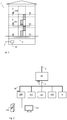
- Fig. 1 illustrates, by way of example, a construction complex 1 in the form of a single building.
- the construction complex 1 may e.g. be a block of apartments or a hotel.
- a coaxial network 2 is provided in the construction complex 1, having sockets in all or a plurality of the different building units, such as building units 4 and 5. Both apartment buildings and hotels normally have a coaxial network covering all apartments or hotel rooms for TV signal distribution.
- a network management unit 10 is connected to the coaxial network 2, and connected to an external data channel 3, such as a supply data cable or an optical fiber.
- the network management device 10 may e.g. be installed in a basement, as illustrated, or on a loft of the building 1, and may be connected after a TV amplifier.
- the network management device 10 may make use of the previously un-used frequency spectrum above the regular TV spectrum (5 - 790 MHz) in coaxial cables for data transportation.
- the network management device 10 is configured to merge an incoming data stream from the external data channel 3 and a TV-signal, where applicable, into the same cable and to send it through the coaxial network 2.
- the signals are divided by an end device 100, 101, such as an access modem, e.g. operating under a MoCA specification. Since the data stream and TV-signal are using separate frequency spectrums, the TV signal is effectively isolated from the data stream.
- an end device 100 such as an access modem, e.g. operating under a MoCA specification. Since the data stream and TV-signal are using separate frequency spectrums, the TV signal is effectively isolated from the data stream.
- Fig. 2 illustrates the basic architectural structure of a system according to one embodiment, where the network management device 10 is shown at the top, connected between an external data channel 3 and a coaxial network 2.
- a plurality of node devices, such as MoCA end devices, 100-104 are connected to the coaxial network 2, operable to obtain access to the external data channel 3 through the network management device 10.
- a node device 100 may receive television signals over the coaxial network 2 for output on a connected TV set 202, which may include or be connected through a set top box (not shown).
- the node device 100 may be configured to provide network access to a connected computer 201, usable for receiving multimedia data.
- the node device 100 may further comprise a wireless access point, for radio access to the node device 100 from various portable radio communication devices such as computers, mobile phones, tablets etc. Further configuration and operation of the system will be described with reference to the drawings of the network management device 10 and node device 100, respectively, by way of example.
- a coaxial network in which a data communication or access network, provided e.g. by means of a MoCA system, is embodied may be of a star type, or a cascade type, or a combination thereof.
- the actual structure of the physical cables may in fact be unknown, since cable charts may have gone missing. This makes it even more difficult to know how far apart two node devices actually are located, signal wise. Synchronization of absolute frequency between all node devices may conveniently be solved by introduction of a reference signal in the coaxial network.
- this reference signal may be a GPS based reference signal provided from the management unit 10.
- a phase locked loop (PLL) in each end device 100, 101 may be configured to frequency lock to the reference.
- a common frequency may not provide sufficient performance for localization, since the reference signal arrives at different time instants to each node device 100, 101, when the coaxial network 2 has different cables lengths for each connection path.
- Each node device may need a trigger signal occurring at the same time instant triggering a localization measurement, measurement operation or other application requiring node devices to start a process or hardware function at the same time instant. Furthermore, this trigger signal can't be sent together with the reference signal since it would arrive at different time instants to the node devices.
- a solution for providing proper synchronization is to determine time delays associated with propagation time between two or more node devices in the coaxial network. It may be sufficient to determine the time delays from a management device node n 0 to two other end node devices n 1 and n 2 , which delays may then be referred to as d (0,1) and d (0,2) . This may be enough where these two end node devices are to be used in a synchronized manner. In another embodiment, all time delays d 0,1 -d 0,k between a management device node and all further end node devices n 1 -n k are determined.
- all delays d i,j are determined between each pair of node devices among a plurality of node devices. This way, all delays within the data communication network of node devices may be determined. Once the time delays are known all devices are synchronized in the sense that they may adjust a respective local time delay relative to a trigger signal sent from the management device.
- the trigger signal may be provided in the form of a reference signal, in which the trigger may be a certain pattern in the reference signal.
- a trigger signal may be accomplished by turning on the reference signal or sending a pulse of the reference signal, at a certain point in time.
- the reference signal is preferably sent on a frequency that is not interfering with other signals in the coaxial network and that has properties that make it propagate without problems in the coaxial network.
- the reference signal is thus preferably separate from data communication signals, such as MoCA signals.
- the reference signal is thus preferably transmitted at a frequency which lies outside a bandwidth for data communication and/or signaling in the data communication network and system. Also, the reference signal must not interfere with airborne radio signals in case the coaxial network leaks due to bad screening material or loose/open connectors.
- the reference signal should preferably also be sent at a frequency that is not attenuated too much at long cable distances.
- the reference signal frequency should also be high enough so it can cross over any capacitive decoupling that it may pass in the coaxial network.
- a common reference signal is used both for a measurement process to obtain synchronization, and to subsequently trigger a synchronized action in the synchronized node devices.
- each node device receives the signal and a time correction is done based on time delay values obtained during measurement. This way, each node device can work in a synchronous way.
- the first node device may be a MoCA management device 10, comprising a first MoCA chip and being connected to an external data channel 3, whereas and each further node device is a MoCA network end device 100, such as a modem, comprising a further MoCA chip 110 and a network access unit 111 connected to the further MoCA chip.
- the first node device may be embodied as a MoCA end device, such as a modem.
- a common hardware unit including circuits and control functions may be conveniently incorporated in both the MoCA management unit and in the MoCA end devices, wherein control signaling may be employed to operate the hardware units in different modes.
- a radio signal propagates 1 meter in about 3.333 nanoseconds.
- a signal propagates with a speed depending on the cable properties, but typically a signal propagates 1 meter in about 5,3 nanoseconds.
- the length of a coaxial cable can vary but a cable is typically between one meter and several hundred meters in a construction complex. This means that a maximum propagation time from a transmitter to a receiver can be up to 1 microsecond or more.
- a first node device such as a MoCA management device 10 may be configured to send out reference signal F1 onto the coaxial network.
- the reference signal may e.g. be 10.7MHz sine signal, taken from a GPS frequency reference receiver, or a signal converted from such a GPS signal, e.g. at 22.5MHz.
- another high accuracy signal may be provided in the first node device, acting as reference signal F1.
- Each further node device in the data communication network will receive this reference signal F1 at different points in time, due to different cable lengths causing different propagation time.
- the reference signal F1 may be defined as a continuous wave (CW) signal that can be generated with a phase locked loop (PLL) from a high accuracy signal reference, such as a GPS signal source.
- PLL phase locked loop
- the absolute frequency accuracy therefore becomes as good as the frequency source accuracy. The better the frequency accuracy the more accurate the measurement result.
- a typical modern GPS can obtain better than 1ns accuracy with more than one satellite in view and signal processing methods.
- a common output from a GPS is a Pulse Per Second (PPS) signal which can be used to estimate the length of a second on the management unit. Since the reference signal F1 is sent out on the coaxial network, each node device can pick up and use the reference to estimate the length of a second when node-to-node measurement is on-going.
- PPS Pulse Per Second
- the reference signal can be locked by a phase locked loop to be the base for a node device reference signal F1 and F2.
- each further node device is configured to be able to be set to a loopback mode, whereby it is configured to respond to a received reference signal F1 with transmission of a loopback signal F2.
- This loopback signal F2 may be transmitted on a different frequency, which may be separated in the node devices by means of bandpass filters.
- the loopback signal F2 may be transmitted at the same frequency as the reference signal F1, at which they may be separated by using circulators in the respective node devices.
- the first node device is configured to measure a time lapse T between transmitting the reference signal and receiving the loopback signal, which time lapse comprises at least the time lapse due to the double propagation time.
- the loopback signal (F2) may be defined as a continuous wave CW signal that in one embodiment can be generated with a PLL and F1 as reference signal.
- each node device n i in the MoCA network includes a signal generator with output frequency F1 and F2, and a signal detector capable of detecting a signal with frequency F1 and F2.
- each node device preferably also includes two bandpass filters with center frequencies of signals F1 and F2, respectively, and bandwidth BW1 and BW2.
- Transmitter (Tx) and Receiver (RX) bandpass filters may form part of a combiner filter, so that it can be attached to the coaxial network.
- each node device n i preferably includes two analog switches, configured to change between transmitting and receiving mode for the respective frequencies of F1 and F2.
- Fig. 3 illustrates a system setup in which at least the first node device n 0 must be able to measure time lapse T in an accurate way.
- time lapse measurement is accomplished by commencing charging of a capacitor with a constant current upon transmitting reference signal F1, and subsequently measuring a voltage level upon detection of a responding signal F2, a certain time later.
- a sample and hold circuit may be included, configured to hold the voltage level constant while a control unit can sample the voltage level.
- the control unit may be configured to mathematically convert the parameter value to a time lapse T.
- This setup provides a solution for achieving time measurement in a cost-effective and efficient way, rather than an alternative solution making use of a microcontroller for measuring in the nanoseconds range, which normally is more expensive for large volume production.
- a first node device n 0 is always a set to a measurement mode, whereas the further node devices n i are set to a loopback mode, preferably one at a time. This is exemplified in Figs 4 and 5 .
- Fig. 4 schematically illustrates a first node device n 0 , realized as a network management device 10 in one embodiment, comprising a connector 14 for connection to an external data channel 3, such as an optical fiber or other physical carrier of broadband data.
- a connector 13 is provided for connection to a coaxial network 2.
- a MoCA control unit 11 may be provided in the network management device 10, inter alia for controlling communication with further node devices n i , such as MoCA end devices 100 connected to the coaxial network 2.
- the control unit 11 includes a data communication chip 12, such as a MoCA chip 12.
- a MoCA chip is the hardware chip implementing the MoCA protocol and the HW required for fulfilling the MoCA specification, and such chips are available on the market.
- Hardware content in the MoCA chip typically includes baseband radio/power amplifier & Low noise amplifier, mixers, RF-switches, microprocessor, clock circuitry and an Ethernet packet bus of some type.
- MoCA chip makers apply the MoCA specification to the chip design by selection of chip content required to fulfill specification. This may vary depending on MoCA Specification version, of which currently versions 1.0, 1.1, 2.0, 2.5 exist.
- the control unit 11 may be operated to control a MoCA chip in the connected MoCA end devices n i , and to access devices connected to the MoCA chip in such MoCA end devices.
- CATV and MoCA channels may be combined in a combiner 41, which is a frequency band selective device.
- the combiner may combine several MoCA channels and several CATV channels to be distributed to the same coaxial network 2.
- a network management device 10 may have several MoCA channels of different frequencies connected to a combiner and distributed to the coaxial network 2.
- the CATV signals may be origin from a satellite system, terrestrial TV system, fiber optical CATV distribution network or other source of CATV (separate input connectors for such CATV sources are not shown).
- the first node device 10 further includes one or more hardware or software units, comprising different parts shown in Fig. 4 , for measuring a time lapse T. As noted, these units are preferably configured to be set in either measurement mode or loopback mode. This functionality can be integrated into a hardware unit by control signals from a local control unit 42 such as a microcontroller. In a simpler embodiment, a node device may be fixed in one of those modes.
- Fig. 4 illustrates a first node device 10 in a measurement mode, set or fixed, and elements that are not required for measurement mode are left out for the sake of convenience. As already noted, various embodiments are configured to distinguish between outgoing and incoming signals of the same frequency, by using circulators. In the embodiment of Fig.
- a signal transmitter 43 is included, capable of transmitting at least a reference signal F1 of a first frequency.
- the signal transmitter 43 may comprise a signal generator, or it may take the frequency from a received base signal, such as a GPS signal.
- a first bandpass signal 44 may be included, preferably having a center frequency matching F1, and a sufficiently wide bandwidth BW1.
- a signal detector 45 may be connected to receive a loopback signal F2 from a further node n i device through the coaxial cable, preferably via a second bandpass signal 46.
- the second bandpass filter preferably has a center frequency matching F2, and a sufficiently wide bandwidth BW2.
- a signal at the combiner 41 is preferably distinguished by the bandpass filters 44, 46, by means of nonoverlapping bands.
- a measurement unit 47 may be connected to the signal transmitter 43 and to the detector 45. This measurement unit 47 may be configured to measure a parameter value based on time lapse T between transmission of the reference signal F1 and reception of a loopback signal F2, as will be described in further detail below.
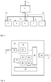
- Fig. 5 illustrates a second or further node device 100, including one or more hardware units comprising different parts, and is configured to loopback mode. This functionality can be integrated into the hardware unit by control signals from a local control unit 52 such as a microcontroller.
- the node device may be fixed in the loopback mode.
- the drawing illustrates a further node device 10 in a loopback mode, set or fixed, and elements that are not required for loopback mode are left out for the sake of convenience.
- the further node device n i in Fig. 5 is a MoCA end device 100, such as an MoCA modem or network adapter.
- a MoCA end device 100 may include a plurality of components, connected to one or more PCBs 114, held in a case (not shown).
- a connector 112 is provided for connection to a coaxial network 2.
- the coax connector 112 is connected to a MoCA chip 110. This may be accomplished by means of a direct connection, or e.g. over a signal combiner 51 as in the illustrated example.
- the MoCA chip 110 may in turn be connected with a management data clock (MDC)/ management data input/output (MDIO) interfaces and an Ethernet bus from General-purpose input/output (GPIO) to a host device 113.
- the host device 113 may be connected with one or more of a Double Data Rate (DDR) memory 1131, host clock circuitry 1132, a boot memory 1133, an operating system memory 1134, and a power supply 1135 for host components and filters.
- DDR Double Data Rate
- the host device 113 may be a master and the MoCA device 110 a slave.
- the host device typically a microprocessor or microcontroller, translates data communication from the MoCA device to all other connected hardware devices, such as indicated devices 111, 117-120, which may include a memory 117 connected by a Serial Peripheral Interface (SPI), LED control 118 connected by GPIO, sensors 119 connected through an I2C interface, an Ethernet switch 111 connected through an Ethernet bus, and a Wi-Fi access point (not shown).
- the Ethernet switch 111 may further be provided with an Ethernet port 57, for connection to an Ethernet cable 58.
- the MoCA chip 110 is the master to the various connected devices, e.g.
- the MoCA chip 110 may also be connected to a host 113 over MDC/MDIO, if needed, which in turn may be connected to various devices 1132-1135 as outlined above.
- the further node device 100 involves a control unit 52, which may be configured by programming to control the operation of the device 100 in the loopback mode.
- the control unit 52 may be addressable by e.g. the management device 10 to set the node device 100 into the loopback mode, e.g. by means of switches. This way, it may be understood by the first node device n 0 which device n i that will return the loopback signal.
- a signal detector 55 is configured to detect receipt of an incoming signal F1.
- a bandpass filter 56 may preferably be provided between the combiner 51 and the detector 55, so as to configure the signal detector 55 to be responsive to F1 specifically, by selection of a corresponding center frequency and bandwidth BW1.
- the signal detector 55 may e.g. be configured to sense a certain signal flank, or the rise of a signal F1 over a certain level, according to the established art.
- a signal transmitter 53 configured to be triggered by detection of an F1 signal by detector F1, e.g. under control of control unit 52.
- the signal transmitter 53 is configured to transmit a loopback signal F2 to the combiner 51, for propagation over the coaxial cable 2.
- Another bandpass filter 54 may be provided between the transmitter 53 and the combiner 51, with a center frequency F2 and bandwidth BW2 corresponding to F2.
- Fig. 6 illustrates, by way of example, a device structure for implementation in a MoCA node device 600 according to the different embodiments described herein.
- This drawing exemplifies a hardware structure that may be employed in any MoCA node device 600 configured to operate in accordance with the embodiments described herein, whether it be a management device 10 (but leaving out a connector for connection to an external data channel) or an end device 100.
- a data communication device such as a MoCA device 60 including a MoCA chip as described above, will not be described further herein.
- the hardware structure of the node device 600 includes at least a combination of the features described with reference to Figs 4 and 5 together with a switch device.
- the MoCA node device 600 has a connector 13 for connection to a coax cable 2, and a signal combiner 61 connected to the connector 13.
- the node device 600 further comprises a signal transmitter 63, which may include a signal generator, capable of transmitting a signal F1 and a signal F2. Alternatively, separate signal generators 43 and 53 may be included in the transmitter 63.
- the transmitter 63 preferably configured to selectively transmit any of at least the two frequencies of reference signal F1 and loopback signal F2. Alternatively, the transmitter may be configured to transmit a broadband signal that may be filtered into F1 or F2.
- the transmitter 63 is nevertheless connected to the combiner 61 through bandpass filters; one filter 64 for passing F1 and one filter 66 for passing F2.
- the node device 600 further comprises a signal detector 65.
- This signal detector 65 may comprise one detector 45 sensitive to at least a signal F2 and one detector 55 sensitive to detect a signal F1. Alternatively, detector 65 is sensitive to both F1 and F2.
- a measurement unit 47 may also be included, connected to the signal transmitter 63 and the signal detector 65.
- the node device 600 is configured into measurement mode by means of a control unit 62, e.g. executed by means of a switch 67.
- the transmitter 63 is then configured to transmit F1 to the combiner, and to receive F2 to the detector 65, in the switch setting as shown in the drawing.
- the node device 600 may thereby operate as described with reference to Fig. 4 .
- the node device 600 is instead configured to operate in loopback mode. This may e.g. be set by a control unit of a management device 10, which communicates with a further device 600 so as to set said further device 600 into loopback mode.
- the device 600 is configured to detect a reference signal F1 in the detector 65.
- the detection of the reference signal F1 triggers the transmitter 63 to emit an F2 signal, as described with reference to Fig. 5 .
- the reference signal F1 may subsequently also be used for operating the synchronized data communication network, such as a MoCA network.
- a node device 600 may be configured to be set to an operational mode, where it is configured to detect F1, but preferably not to respond with a loopback signal F2. This setting may be accomplished with the switch 67, or e.g. by the control unit 62 disconnecting or turning off the signal transmitter 63.
- the reference signal F1 may be conveyed to the data communication device, such as a MoCA chip 60 as a common clock reference signal 66, which may be used in a Phase-Locked Loop (PLL).
- PLL Phase-Locked Loop
- a trigger signal 67 may be received with the reference signal F1 and detected by the signal detector 65, which trigger signal will be connected to a delay unit 68.
- the delay unit 68 may in turn be connected to transmit an activation signal 69 delayed by a determined time delay, which time delay may be stored in a memory 621, accessible by means of the control unit 62.
- the activation signal may be relayed to the MoCA chip 60 or to other circuits in the node device 600. This may typically be made under control of the control unit 62, and may involve retrieving accurate time delay data from the memory 621, pertaining to a suitable delay to be applied dependent on from which other node device the trigger signal 67 is received.
- the first node device 10 which is configured to measuring mode is preferably in control of the process for measuring a time lapse T, e.g. by means of control unit 42.
- Start of a measurement involves activating the signal transmitter 43. This may be a signal transmission triggered by the control unit 42.
- a reference signal F1 provided by the signal transmitter 43 may be a pulse train or similar, such that each pulse or on-period has a leading edge when the amplitude rises, that may be taken as a trigger for a time lapse measurement.
- Starting a measurement thus involves substantially simultaneously activating both the measurement unit 47 and the signal transmission of F1.
- activating the measurement unit 47 involves charging of a measurement capacitor in the measurement unit 47.
- the transmitter enabled with a frequency of signal F1, transmit a signal F1 which exits through the combiner unit 41 and onto the coaxial network 2.
- the signal F1 has propagated through the coaxial network 2 and enters the signal detector 55 of a node device 100 configured for Loopback mode.
- the F1 signal When the F1 signal is detected it instantly triggers activation of a transmitter 53, which may include a signal generator of frequency F2, which transmitter 53 sends a signal F2 out through the combiner unit 51 and back on the coaxial network 2.
- the loopback signal F2 enters the combiner unit 41 of the first node device 10, and is received by the signal detector 45 after passing bandpass filter 46.
- the measurement unit 47 is immediately triggered.
- a sample and hold unit samples the instantaneous voltage over a capacitor, which capacitor was subjected to charging upon detecting transmission of the reference signal F1.
- the control unit 42 may then be configured to read out a parameter value in the form of the voltage from the sample and hold circuit, e.g. by means of an analog to digital conversion. Dependent on known characteristics of the capacitor circuit, this voltage may subsequently be converted to a time lapse T.
- F1 is preferably sent out with zero phase from the transmitter. This may be done by detecting the voltage crossing of zero volt with a zero-crossing detector. As soon as the crossing is detected F1 is sent out through the transmitter. Simultaneously as F1 is transmitted, a capacitor C of the measurement unit starts charging through a resistor R. Since the RC-network is composed of analog passive components, no variance of any significance between measurements will be contributed from the time lapse measuring logic or its activation. This is because activation pulse jitter affects both the RC-charging and the transmitter activation in the same way.
- the signal detector 45, 55, 65 may comprise three parts, all of which may be constructed by operational amplifiers:
- the voltage rectification can be performed at relatively low frequencies (up to several hundred MHz possible) this operation can be performed with an operational amplifier precision rectifier circuit. Since the received signal is rectified it does not matter if it is sent out positively or negatively by the transmitter.
- a voltage peak detector and averaging unit smooths out the rectified voltage waveform.
- the simplest circuit could comprise a diode, capacitor and a parallel resistor, sourcing capacitor charge current from the full wave rectifier through the diode when the signal is detected, and the parallel resistor discharging capacitor current in absence of a received signal.
- a voltage comparator for level detection.
- a detect level provided as a first input for the comparator may be set to be above the thermal noise voltage from the peak/averaging unit when there is no present signal.
- the other comparator input is connected to the peak/averaging unit. When a signal is received, the voltage level will rise from the peak/averaging unit and the comparator will output a "signal presence" flag or signal.
- an "F1 signal presence" flag enables the transmitter 53 to transmit F2 in response to receipt of F1.
- F2 is sent out initially either positively or negatively form the loopback device transmitter.
- a full wave rectifier subsequently rectifies the signal to a positive voltage F2 rect in the measurement unit of the node device receiving the loopback signal F2 rect .
- an "F2 signal presence" flag is used to disconnect charging of the capacitor C in the RC-network.
- the control unit 42, 62 can measure the voltage level of the capacitor with an analog to digital converter. This measurement is not critical to do fast as the capacitor is retaining its voltage until the measurement is done. The capacitor is then set to zero voltage and another measurement cycle may begin. This may involve sending a control signal to the node device for which the measurement is completed to disconnect the loopback mode, and to instead enter an operational mode. A control signal may further be sent to another node device, setting it to loopback mode.
- the time lapse T measured by the measurement unit 47 is typically longer than only the time required for the signals F1 and F2 to propagate through the coaxial network 2.
- the time lapse T also contains a time period contributed by the analog and digital circuitry. However, this time period is typically almost constant, and the small variation can be accounted for by doing several measurements and averaging the result.
- Time periods forming part of the total time lapse T include but is not limited to:
- the constant part of the time lapse T that is not related to coaxial cable propagation time can be subtracted from the time lapse T by connecting a measurement mode hardware unit to a loopback mode measurement hardware unit and averaging several time lapse results.
- a time measuring RC network When measuring a time lapse, a time measuring RC network may be employed.
- V 0 is the voltage which generates the charge current over R. Since only V(t) is depending on time lapse (t) the calculation of time lapse can be done if V(t) is known.
- This parameter value V(t) is preferably sampled in the measurement unit 47 under control of the control unit 42.
- the detection of signal F2 triggers a sample event, the time lapse voltage cannot be allowed to change until the control device have sampled the voltage level. This will happen if the charging of the capacitor will continue.
- a sample and hold circuit is triggered very fast by the F2 detector and then holds the voltage at a constant level until the control device has sampled the voltage. The control device then clears (zeroes) the capacitor voltage and a new measurement can start.
- a transmitter 63 is required for sending either the F1 signal or the F2 signal. Since either the loopback mode or the measuring mode is selected, only one transmitter is required in each mode. Therefore, only one transmitter could be used provided that it may be configured to operate at two frequencies (F1 and F2). This would reduce the hardware costs and complexity of the design.
- a signal detector 65 is required for sensing the presence of either F1 or F2. Since either the loopback mode or the measuring mode is selected only one detector is required in each mode. Therefore, only one detector could be used if it can be configured for two frequencies (F1 and F2), which again would reduce the hardware costs and complexity of the design. If the frequencies F1 and F2 are chosen closely together a detector could be constructed that is wideband enough to detect both frequencies and it would then be the band pass filters that separate them. For detection of a F1 or F2 signal a full-wave rectifier and a diode detector can be used to sense presence of the signal arriving to the detector. The diode detector output can be amplified by an operational amplifier and a trigger voltage level can be set. The output can then trigger the sample and hold circuit or F2 transmitter.
- Bandpass filters 44 and 46 are configured to block unwanted signals from entering the detector.
- the bandwidth BW1, BW2 must be large enough to enable fast rise times of the signals F1 and F2.
- the bandwidth must be large enough to make the rise times negligible compared to the total time lapse measurement period.
- the bandwidth in the coaxial network is so large that it will not influence the rise time.
- Rise times in the analog circuitry can with todays integrated circuit technology be kept small enough for an accurate measurement. A too long rise time though would impact the performance at short distance measurements, so the bandwidth should be kept high enough. For example, a 35MHz bandwidth filter would achieve 10ns rise time.
- the switch 67 indicated in Fig. 6 may be realized by means of bidirectional analog switches, configured to short circuit analog voltage from input/output to any of the two inputs/outputs.
- the switches serve to configure whether each frequency channel F1 or F2 are either in transmit or receive mode.
- the switch rise time is negligible and the switchover delay between output states does not affect the time lapse measurement since the switchover is done before the measurement starts.
- a data communication network over a coaxial cable 2 including at least a first node device n 0 and a plurality of further nodes n 1 -n k .
- propagation time T a,b between nodes a and b may be established, by measuring the time lapse between transmission of a reference signal and reception of a loopback signal. In one approximation, this time lapse may be taken as the double propagation time. In a more detailed approximation, a constant part may be subtracted from the measured time lapse, as described, to calculate the propagation time. As indicated in Fig.
- At least the propagation time T 0,i between the first node device n 0 and each further node device n i may thus be established. This result may subsequently be used for determining time delay values d 0,i , based on the time lapse between transmitting the reference signal and receiving the loopback signal in at least the first node device n 0 .
- the propagation time T i,j between any pair of node devices within the plurality of node devices may be established. This may be obtained by controlling any node device i to act as a first node device, for transmitting a reference signal and receiving a loopback signal, together with another node device j.
- the results in this establishment of propagation time is then reported by the node device i to a node device incorporated in a data communication management device 10.
- the obtained result may subsequently be used for determining time delay values d 0,i , for application between the first node n 0 device and a further node device n i , or even d i,j , for application between any two node devices n i device and n j , based on the time lapse between transmitting the reference signal and receiving the loopback signal.
- the determined time delay values d i,j are stored or formatted as a time delay matrix D, including time delay values for every path in the coaxial network where the ends are connected by a hardware circuit in a node device, which hardware circuit may be configured in either measurement mode or loopback mode.
- Each time lapse value corresponds to and can be converted to an approximate length of a coaxial cable path from measuring unit to loopback unit.
- Each node device in the network can then implement a local time delay unit 68, that delays a trigger signal received from a first node device, such as the data communication management device 10.
- the delay unit 68 is preferably configured to delay the trigger signal such that an activation signal 69 provided from the delay unit 68 executes an action substantially simultaneously in a plurality, or all, node devices.
- time lapse values T i,j which at least approximately represent propagation time between node devices n i and n j , have been established.
- T i max is the largest time lapse established from node n i to any of the other node devices
- k may be a constant having a value ⁇ 0.
- K 10 ⁇ s would corresponds to nearly 2 km of coax cable, more than could be expected in most building complexes as a distance between the farthest pair of node devices.
- one node device acting as a first node device no will address a further node device n i , signaling said further node device to enter loopback mode.
- This may e.g. be obtained by means of the control channel as described in the referenced prior applications EP16178618.1 and US15/341,739 . Every other node device in the data communication network connected to the same coaxial cable will thus ignore the signal F1.
- the first node device starts the measurement and calculates the time lapse to the other node device and stores it, e.g. in a time lapse table.
- the first node device then deselects the addressed node device by signaling it to leave loopback mode, and continues with a next node device in a list of node devices of the data communication network, and the cycle starts over. This may continue until all time lapses are known, either only with respect to the first node device, e.g. the management device, or with respect to all node devices.
- the time lapse data can then be used for determining time delay values, usable for synchronizing data communication end devices together by locally, in the respective node device, delaying a received signal, such as a reference clock based trigger. This may e.g. be accomplished with a phase locked loop and/or a delay locked loop.
- control device must be able to control locally added delay in small steps so that the time delay resolution is sufficient for the application on the data communication end device. For example, to attain 1m resolution steps of approximately 5ns would be required, and a 1 ⁇ s or more total delay required if a 1m and 250m cable would be paralleled on different coaxial cable branches in a star network.
- a management device 10 may control the process, and may configure one node device which is incorporated in a data communication end device 100 to measurement mode and perform the measurement with respect to another node device of a data communication end device 101 which is set to loopback mode.
- the management device 10 then reads back the result of the establishment of the time lapse value, and stores it in a time lapse table. Then the management device 10 may shift modes of both data communication end devices 100, 101 and start the measurement again in the reverse order, and subsequently saves the result. Then it continues with all possible combinations until all time lapses are known, as indicated in Fig. 3 .
- a node n 0 may be a MoCA management device 10
- node devices n 1 -n k are MoCA end devices 101-k.
- the time delay value to itself is preferably always zero for any node.
- Fig. 7 schematically illustrates a data communication network according to one simplified embodiment, in line with any of the embodiments described above.
- a delay value matrix determined based on the principles outlined with this example may be compiled and subsequently transmitted from e.g. a management device 10 acting as a first node device n 0 , to all other node devices n 1 -n 4 . In the respective node device, it may be stored as data in a memory 621, accessible by means of a control unit 62.
- a node device n j may thus be configured to operate in a loopback mode in a data communication network with a further node device n i operating in a measurement mode, where these node devices are connected via a coaxial network 2.
- the loopback node device n j may be configured as the node device 600 exemplified in Fig. 6 , and comprise a connector 13 for connecting to a coaxial network 2, and a signal detector 65, connected to the connector, which signal detector 55 is configured to detect a reference signal F1 received from a connected coaxial network.
- a signal transmitter 63 connected to the signal detector 55 may thus be configured to transmit a loopback signal F2 responsive to the detector detecting a reference signal.
- the node device n i configured to operate in measurement mode in the data communication network also has a connector 13 for connecting to a coaxial network, and may be configured as the node device 600 in Fig. 6 .
- the measurement node device comprises a signal transmitter 63, connected to said connector, which is configured to transmit the reference signal to the coaxial network for reception by the loopback node device n j .
- the node device n i configured to operate in measurement mode further comprises a measurement unit 47, connected to the signal transmitter 63, and also connected to receive a loopback signal F2 from the node n j to which the reference signal was sent.
- the measurement unit 47 is configured to measure a parameter value based on time lapse T i,j between transmission of the reference signal F1 and reception of the loopback signal F2 in the node device n i configured to operate in measurement mode.
- a control unit 62 in the node device n i configured to operate in measurement mode is preferably further configured to determine a time delay value d i,j dependent on the measured parameter value, and to send a control signal for reception by the further node device, indicating said time delay value.
- the time delay value d i,j is preferably subsequently sent to the node device n j , and stored in a memory 621 therein.
- the time delay value may later be used for operating e.g. the MoCA system to execute an action substantially simultaneously in plural node devices n, in an operational mode, or synchronized mode.
- the node device n j therefore preferably comprises a delay circuit 68, configured generate an activation signal 69 by applying a time delay value to a trigger signal 67 received by the signal detector 65.
- the time delay time delay value is preferably retrieved from the memory 621 by means of the control unit 62, and the appropriate d i,j is thereby selected which is associated with a propagation time through the coaxial network between the node devices n i and n j .
- the control unit 62 is thereby configured to trigger execution of an action by means of the activation signal, which will then be activated substantially simultaneously in plural node devices which receive the same trigger signal 67 at different time instances, due to different propagation paths from the node n i transmitting the signal F1 carrying the trigger signal.
- a node device thus only listens for a reference signal F1 to create trigger pulses with its pre-set delay.
- a node device may implement a digital delay circuit, i.e. Delay Locked Loop to change the phase of the "signal presence" signal. This way, F1 can be used as the trigger signal. This feature is present even if the loopback function is active or not.
- the DLL of two node devices may thus be adjusted to achieve the same phase of the resulting two trigger signals in the respective two node devices.
- the adjustment value that is set on the DLL on a node device is transferred by the data communications network, in one embodiment as ethernet traffic from the management unit to a control unit on the node device.
- the management unit is further configured to coordinate the measurement process to set node devices in their required mode for operation in any of the three modes; measurement mode, loopback mode or operational mode.
- signal frequencies that lie outside the operational bandwidth of the data communication system, rather than data packets of the data communication network, negative effects on measurements caused by e.g. jitter, and effects caused by the network processor workload dependent on packet size, of the involved node devices, are alleviated. Also, the need for averaging is minimized.
- the measurement method described may be done without using any digital processing circuitry, thereby avoiding time delay variances without costly component arrangements. Delays not related to propagation time are predictable and repeatable, and may be accounted for in a calibration process with a "zero meter" cable at the design or production stage.
Landscapes
- Engineering & Computer Science (AREA)
- Signal Processing (AREA)
- Computer Networks & Wireless Communication (AREA)
- Environmental & Geological Engineering (AREA)
- Multimedia (AREA)
- Automation & Control Theory (AREA)
- Small-Scale Networks (AREA)
- Mobile Radio Communication Systems (AREA)
- Synchronisation In Digital Transmission Systems (AREA)
- Cable Transmission Systems, Equalization Of Radio And Reduction Of Echo (AREA)
Claims (10)
- Verfahren zur Synchronisation eines Datenkommunikationsnetzes, das mehrere Knotenvorrichtungen beinhaltet, die über ein Koaxialnetz miteinander verbunden sind und ausgelegt sind zur Datenkommunikation in einem MoCA- bzw. Multimedia-over-Coaxial-Alliance-Zugangsnetz innerhalb einer vorbestimmten Frequenzbandbreite, umfassend die folgenden Schritte:Übertragen eines Referenzsignals mit einer Frequenz außerhalb der Bandbreite von einer ersten Knotenvorrichtung auf das Koaxialnetz;Empfangen eines Loopback-Signals mit einer Frequenz außerhalb der Bandbreite von einer weiteren Knotenvorrichtung über das Koaxialnetz;Bestimmen eines Zeitverzögerungswerts basierend auf einer Zeitspanne zwischen dem Übertragen des Referenzsignals und dem Empfangen des Loopback-Signals;wobei die Schritte des Übertragens, Empfangens und Bestimmens für jedes Paar von Knotenvorrichtungen unter den mehreren Knotenvorrichtungen nacheinander ausgeführt werden;Kompilieren, in einer der Knotenvorrichtungen, die als Verwaltungsvorrichtung (10) agiert, einer Matrix, die Zeitverzögerungswerte beinhaltet, die mit der Zeitverzögerung zwischen jedem Paar von Knotenvorrichtungen unter den mehreren Knotenvorrichtungen assoziiert sind; undSenden der Matrix von der Verwaltungsvorrichtung an jede weitere Knotenvorrichtung der mehreren Knotenvorrichtungen.
- Verfahren nach Anspruch 1, wobei das Referenzsignal ein Dauerstrichsignal einer vorbestimmten Frequenz ist.
- Verfahren nach Anspruch 2, wobei das Referenzsignal gleichzeitig mit einer Initiierung eines Ladens eines Kondensators übertragen wird und wobei ein Detektieren eines Empfangs des Loopback-Signals das Laden des Kondensators stoppt.
- Verfahren nach einem der vorhergehenden Ansprüche, wobei das Referenzsignal eine Impulsfolge ist und wobei eine Vorderflanke der Impulsfolge eine Messung eines Zeitverzögerungswerts triggert.
- Verfahren nach einem der vorhergehenden Ansprüche, wobei die erste Knotenvorrichtung eine Netzverwaltungsvorrichtung ist und wobei die Schritte des Übertragens, Empfangens und Bestimmens nacheinander mit jeder weiteren Knotenvorrichtung der mehreren Knotenvorrichtungen ausgeführt werden.
- Verfahren nach einem der vorhergehenden Ansprüche, umfassend den Schritt zum Übertragen eines Steuersignals von der ersten Knotenvorrichtung auf das Koaxialnetz, wodurch eine einzige weitere Knotenvorrichtung zum Agieren als Loopback-Knoten getriggert wird, wobei der einzige weitere Knoten zum Übertragen des Loopback-Signals als Reaktion auf Empfangen des Referenzsignals ausgelegt ist.
- Verfahren nach einem der vorhergehenden Ansprüche, wobei das Referenzsignal mit einer ersten Frequenz übertragen wird und das Loopback-Signal mit einer zweiten Frequenz empfangen wird.
- Verfahren nach einem der vorhergehenden Ansprüche, wobei das Loopback-Signal mit einer Frequenz empfangen wird, die ein ganzzahliges Produkt der Frequenz des Referenzsignals ist.
- Verfahren nach einem der vorhergehenden Ansprüche, wobei das Referenzsignal eine Frequenz F1 aufweist und das Loopback-Signal eine Frequenz F2 aufweist, die n*F1 beträgt, wobei n eine ganze Zahl von mindestens 2 ist.
- Verfahren nach einem der vorhergehenden Ansprüche, wobei das Datenkommunikationsnetz ein Zugangsnetz ist, in dem die erste Knotenvorrichtung mit einem Breitbanddatenkanal verbunden ist und einen Zugang zu dem Breitbanddatenkanal für die weiteren Knotenvorrichtungen steuert.
Applications Claiming Priority (2)
| Application Number | Priority Date | Filing Date | Title |
|---|---|---|---|
| EP16202957.3A EP3334090A1 (de) | 2016-12-08 | 2016-12-08 | Verfahren und system zur synchronisierung von knotenvorrichtungen in einem koaxialnetzwerk |
| PCT/SE2017/051239 WO2018106178A1 (en) | 2016-12-08 | 2017-12-08 | Method and system for synchronization of node devices in a coaxial network |
Publications (3)
| Publication Number | Publication Date |
|---|---|
| EP3552311A1 EP3552311A1 (de) | 2019-10-16 |
| EP3552311A4 EP3552311A4 (de) | 2020-08-19 |
| EP3552311B1 true EP3552311B1 (de) | 2021-09-15 |
Family
ID=57629235
Family Applications (2)
| Application Number | Title | Priority Date | Filing Date |
|---|---|---|---|
| EP16202957.3A Withdrawn EP3334090A1 (de) | 2016-12-08 | 2016-12-08 | Verfahren und system zur synchronisierung von knotenvorrichtungen in einem koaxialnetzwerk |
| EP17878187.8A Active EP3552311B1 (de) | 2016-12-08 | 2017-12-08 | Verfahren zur synchronisierung von knotenvorrichtungen in einem koaxialnetzwerk |
Family Applications Before (1)
| Application Number | Title | Priority Date | Filing Date |
|---|---|---|---|
| EP16202957.3A Withdrawn EP3334090A1 (de) | 2016-12-08 | 2016-12-08 | Verfahren und system zur synchronisierung von knotenvorrichtungen in einem koaxialnetzwerk |
Country Status (5)
| Country | Link |
|---|---|
| US (1) | US10749779B2 (de) |
| EP (2) | EP3334090A1 (de) |
| CN (1) | CN110100388B (de) |
| CA (1) | CA3042336C (de) |
| WO (1) | WO2018106178A1 (de) |
Families Citing this family (8)
| Publication number | Priority date | Publication date | Assignee | Title |
|---|---|---|---|---|
| EP3468099B1 (de) * | 2017-10-09 | 2020-03-04 | InCoax Networks AB | Verfahren und vorrichtung zur analyse einer koaxialen netzwerkinfrastruktur |
| JP2019146014A (ja) * | 2018-02-20 | 2019-08-29 | 日本電信電話株式会社 | 時刻同期システム及び時刻同期方法 |
| JP6939664B2 (ja) * | 2018-03-14 | 2021-09-22 | オムロン株式会社 | センサ管理装置、センサ情報同期方法、制御プログラム、及び記録媒体 |
| CN110175091B (zh) * | 2018-12-11 | 2023-06-23 | 中国航空工业集团公司西安航空计算技术研究所 | 一种Lockstep架构下的节点间信号同步方法、装置及电路 |
| CN112087328B (zh) * | 2020-08-27 | 2022-07-29 | 西安理工大学 | 基于最优节点选择策略的复杂时滞网络同步与辨识方法 |
| US11337133B1 (en) * | 2021-02-08 | 2022-05-17 | InContact Inc. | Systems and methods for optimal channel selection |
| CN113078978A (zh) * | 2021-03-26 | 2021-07-06 | 杭州加速科技有限公司 | 远距离多ate半导体测试设备同步方法、系统及测试方法 |
| EP4191953A1 (de) * | 2021-12-06 | 2023-06-07 | InCoax Networks AB | Datenkommunikation in einem moca-zugangsnetzwerk |
Family Cites Families (25)
| Publication number | Priority date | Publication date | Assignee | Title |
|---|---|---|---|---|
| US6195362B1 (en) * | 1996-11-08 | 2001-02-27 | At&T Corporation | Resource pooling system and method in communication systems |
| JP3180735B2 (ja) * | 1997-10-22 | 2001-06-25 | 松下電器産業株式会社 | 送信タイミング補正機能付き無線端末及びその製造方法 |
| US6956865B1 (en) * | 2000-01-07 | 2005-10-18 | Cisco Technology, Inc. | Technique for dynamically adjusting lookahead time for channel map messages to achieve optimal packet performance over an access network |
| WO2006096668A2 (en) * | 2005-03-07 | 2006-09-14 | Nettest North America, Inc. | Passive optical network loss test apparatus and method of use thereof |
| JP5220841B2 (ja) * | 2007-04-07 | 2013-06-26 | エントロピック・コミュニケーションズ・インコーポレイテッド | 通信ネットワークを形成するための周波数走査 |
| US20080271076A1 (en) * | 2007-04-27 | 2008-10-30 | General Instrument Corporation | Method and Apparatus for Switching Between Edge Device Resources in an SDV System |
| DE102007026684B4 (de) | 2007-06-08 | 2009-03-19 | Gesellschaft für Schwerionenforschung mbH | Zeit-Amplituden-Konverter-Bauelement |
| US8363681B2 (en) * | 2008-10-16 | 2013-01-29 | Entropic Communications, Inc. | Method and apparatus for using ranging measurements in a multimedia home network |
| US9106435B2 (en) * | 2008-12-04 | 2015-08-11 | Cisco Technology, Inc. | Efficient data transmission within MoCA |
| US8213309B2 (en) * | 2008-12-22 | 2012-07-03 | Broadcom Corporation | Systems and methods for reducing latency and reservation request overhead in a communications network |
| US8121023B2 (en) * | 2009-09-21 | 2012-02-21 | Intel Corporation | Coaxial network communication node and methods for communicating multimedia over a coaxial network with reduced-length cyclic prefixes |
| US8806044B2 (en) * | 2011-11-29 | 2014-08-12 | Maxlinear, Inc. | Method and system for cross-protocol time synchronization |
| US9001904B2 (en) * | 2010-03-03 | 2015-04-07 | Lantiq Deutschland Gmbh | Multi-carrier clock transport and synchronization |
| US20110274156A1 (en) * | 2010-05-05 | 2011-11-10 | Cavium Networks | System and method for transmitting multimedia stream |
| US8831015B2 (en) * | 2011-05-10 | 2014-09-09 | Entropic Communications, Inc. | MoCA-WiFi multiplexing |
| WO2012161581A1 (en) * | 2011-05-24 | 2012-11-29 | Stichting Vu-Vumc | System and method for network synchronization and frequency dissemination |
| US8813135B2 (en) * | 2011-11-21 | 2014-08-19 | Maxlinear, Inc. | Method and system for providing a home cable network |
| WO2013106356A1 (en) * | 2012-01-09 | 2013-07-18 | Shlomo Selim Rakib | Hfc cable system with wideband communications pathway and coax domain nodes |
| CN102638324B (zh) * | 2012-03-27 | 2014-12-17 | 杭州华三通信技术有限公司 | 一种实现精确时间同步的方法和装置 |
| US9008571B2 (en) * | 2012-08-22 | 2015-04-14 | Maxlinear, Inc. | Method and system for a single frequency network for broadcasting to mobile devices |
| US9246583B2 (en) * | 2012-12-28 | 2016-01-26 | Futurewei Technologies, Inc. | Method and apparatus for measuring round trip delay in a unified optical-coaxial network |
| WO2014186624A1 (en) * | 2013-05-15 | 2014-11-20 | Entropic Communications, Inc. | Hybrid wired and wireless network communication system and method |
| US10574583B2 (en) * | 2013-07-30 | 2020-02-25 | Entropic Communications, Llc | Method and apparatus for combined access network and home network using a dual-role device |
| EP3132651B1 (de) * | 2014-04-15 | 2018-10-17 | Telefonaktiebolaget LM Ericsson (publ) | Erster netzwerkknoten, zweiter netzwerkknoten und verfahren darin |
| US9699507B2 (en) * | 2015-01-12 | 2017-07-04 | Time Warner Cable Entrprises Llc | Addressing and locating in-line coaxial cable devices within customer premises in cable-based networks |
-
2016
- 2016-12-08 EP EP16202957.3A patent/EP3334090A1/de not_active Withdrawn
-
2017
- 2017-02-02 US US15/422,718 patent/US10749779B2/en active Active
- 2017-12-08 CN CN201780075718.9A patent/CN110100388B/zh active Active
- 2017-12-08 CA CA3042336A patent/CA3042336C/en active Active
- 2017-12-08 EP EP17878187.8A patent/EP3552311B1/de active Active
- 2017-12-08 WO PCT/SE2017/051239 patent/WO2018106178A1/en not_active Ceased
Also Published As
| Publication number | Publication date |
|---|---|
| WO2018106178A1 (en) | 2018-06-14 |
| US20180167299A1 (en) | 2018-06-14 |
| CN110100388A (zh) | 2019-08-06 |
| CN110100388B (zh) | 2023-04-28 |
| EP3552311A1 (de) | 2019-10-16 |
| US10749779B2 (en) | 2020-08-18 |
| EP3334090A1 (de) | 2018-06-13 |
| EP3552311A4 (de) | 2020-08-19 |
| CA3042336A1 (en) | 2018-06-14 |
| CA3042336C (en) | 2025-06-17 |
Similar Documents
| Publication | Publication Date | Title |
|---|---|---|
| EP3552311B1 (de) | Verfahren zur synchronisierung von knotenvorrichtungen in einem koaxialnetzwerk | |
| TWI454879B (zh) | 用以於可擴充的且時序關鍵的系統中分配準確的同步化時間戳記之系統,方法,及裝置 | |
| AU2007215381B2 (en) | Distributed synchronization and timing system | |
| CN101078763B (zh) | 在ip网络中依靠卫星定位系统校准时钟频率的方法及设备 | |
| CN106470428B (zh) | 一种并行多通道信道测试设备的精确同步与触发方法 | |
| CA2755750A1 (en) | Synchronisation and timing method and apparatus | |
| JP2012527660A5 (de) | ||
| EP2965458A1 (de) | Dithering-schaltung zur seriellen datenübertragung | |
| CN115001491B (zh) | 多片adc采样时钟阵列的同步采样方法及装置 | |
| US7944904B2 (en) | Systems and methods for managing timing functions in multiple timing protocols | |
| US20030058893A1 (en) | Synchronization of multiple cable modem termination systems | |
| CN105450320B (zh) | 一种智能变电站全程us级精度无线以太网络同步装置及方法 | |
| EP3695564B1 (de) | Verfahren und vorrichtung zur analyse einer koaxialen netzwerkinfrastruktur | |
| CN113960682A (zh) | 一种基于fpga的多通道数字相关器及其相关方法 | |
| Exel et al. | A novel, high-precision timestamping platform for wireless networks | |
| CN201114098Y (zh) | 具有GPS授时校频功能的TDMoverIP设备 | |
| US9049020B2 (en) | Circuitry to facilitate testing of serial interfaces | |
| KR100842683B1 (ko) | 다중 안테나를 이용한 무선 채널 측정 시스템에서의 타이밍 동기 신호 획득 방법 | |
| Huckeba et al. | Precise time synchronization using IEEE 1588 for LXI applications | |
| JP5238980B2 (ja) | 瞬時に同期を確立しかつ保持できる同期発振器 | |
| Kovacshazy et al. | Low cost field test measurement method and prototype measurement device implementation for timing accuracy evaluation of IEEE 1588 solutions | |
| Kovacshazy | Synchronization performance evaluation of reference clock connection methods for IEEE 1588 master clocks | |
| JP2005117585A (ja) | ダイバーシティ送信機 |
Legal Events
| Date | Code | Title | Description |
|---|---|---|---|
| STAA | Information on the status of an ep patent application or granted ep patent |
Free format text: STATUS: THE INTERNATIONAL PUBLICATION HAS BEEN MADE |
|
| PUAI | Public reference made under article 153(3) epc to a published international application that has entered the european phase |
Free format text: ORIGINAL CODE: 0009012 |
|
| STAA | Information on the status of an ep patent application or granted ep patent |
Free format text: STATUS: REQUEST FOR EXAMINATION WAS MADE |
|
| 17P | Request for examination filed |
Effective date: 20190705 |
|
| AK | Designated contracting states |
Kind code of ref document: A1 Designated state(s): AL AT BE BG CH CY CZ DE DK EE ES FI FR GB GR HR HU IE IS IT LI LT LU LV MC MK MT NL NO PL PT RO RS SE SI SK SM TR |
|
| AX | Request for extension of the european patent |
Extension state: BA ME |
|
| DAV | Request for validation of the european patent (deleted) | ||
| DAX | Request for extension of the european patent (deleted) | ||
| STAA | Information on the status of an ep patent application or granted ep patent |
Free format text: STATUS: EXAMINATION IS IN PROGRESS |
|
| A4 | Supplementary search report drawn up and despatched |
Effective date: 20200722 |
|
| RIC1 | Information provided on ipc code assigned before grant |
Ipc: H04L 12/24 20060101AFI20200716BHEP Ipc: H04L 12/26 20060101ALI20200716BHEP Ipc: H04L 12/28 20060101ALI20200716BHEP Ipc: H04J 3/00 20060101ALI20200716BHEP |
|
| 17Q | First examination report despatched |
Effective date: 20200803 |
|
| REG | Reference to a national code |
Ref country code: DE Ref legal event code: R079 Ref document number: 602017046230 Country of ref document: DE Free format text: PREVIOUS MAIN CLASS: H03L0007060000 Ipc: H04L0012240000 |
|
| GRAP | Despatch of communication of intention to grant a patent |
Free format text: ORIGINAL CODE: EPIDOSNIGR1 |
|
| STAA | Information on the status of an ep patent application or granted ep patent |
Free format text: STATUS: GRANT OF PATENT IS INTENDED |
|
| RIC1 | Information provided on ipc code assigned before grant |
Ipc: H04J 3/06 20060101ALI20210312BHEP Ipc: H04L 12/28 20060101ALI20210312BHEP Ipc: H04L 12/26 20060101ALI20210312BHEP Ipc: H04L 12/24 20060101AFI20210312BHEP |
|
| INTG | Intention to grant announced |
Effective date: 20210407 |
|
| GRAS | Grant fee paid |
Free format text: ORIGINAL CODE: EPIDOSNIGR3 |
|
| GRAA | (expected) grant |
Free format text: ORIGINAL CODE: 0009210 |
|
| STAA | Information on the status of an ep patent application or granted ep patent |
Free format text: STATUS: THE PATENT HAS BEEN GRANTED |
|
| AK | Designated contracting states |
Kind code of ref document: B1 Designated state(s): AL AT BE BG CH CY CZ DE DK EE ES FI FR GB GR HR HU IE IS IT LI LT LU LV MC MK MT NL NO PL PT RO RS SE SI SK SM TR |
|
| REG | Reference to a national code |
Ref country code: CH Ref legal event code: EP |
|
| REG | Reference to a national code |
Ref country code: DE Ref legal event code: R096 Ref document number: 602017046230 Country of ref document: DE |
|
| REG | Reference to a national code |
Ref country code: IE Ref legal event code: FG4D |
|
| REG | Reference to a national code |
Ref country code: AT Ref legal event code: REF Ref document number: 1431390 Country of ref document: AT Kind code of ref document: T Effective date: 20211015 |
|
| REG | Reference to a national code |
Ref country code: DE Ref legal event code: R079 Ref document number: 602017046230 Country of ref document: DE Free format text: PREVIOUS MAIN CLASS: H04L0012240000 Ipc: H04L0041000000 |
|
| REG | Reference to a national code |
Ref country code: NL Ref legal event code: FP |
|
| REG | Reference to a national code |
Ref country code: LT Ref legal event code: MG9D |
|
| PG25 | Lapsed in a contracting state [announced via postgrant information from national office to epo] |
Ref country code: NO Free format text: LAPSE BECAUSE OF FAILURE TO SUBMIT A TRANSLATION OF THE DESCRIPTION OR TO PAY THE FEE WITHIN THE PRESCRIBED TIME-LIMIT Effective date: 20211215 Ref country code: LT Free format text: LAPSE BECAUSE OF FAILURE TO SUBMIT A TRANSLATION OF THE DESCRIPTION OR TO PAY THE FEE WITHIN THE PRESCRIBED TIME-LIMIT Effective date: 20210915 Ref country code: BG Free format text: LAPSE BECAUSE OF FAILURE TO SUBMIT A TRANSLATION OF THE DESCRIPTION OR TO PAY THE FEE WITHIN THE PRESCRIBED TIME-LIMIT Effective date: 20211215 Ref country code: SE Free format text: LAPSE BECAUSE OF FAILURE TO SUBMIT A TRANSLATION OF THE DESCRIPTION OR TO PAY THE FEE WITHIN THE PRESCRIBED TIME-LIMIT Effective date: 20210915 Ref country code: RS Free format text: LAPSE BECAUSE OF FAILURE TO SUBMIT A TRANSLATION OF THE DESCRIPTION OR TO PAY THE FEE WITHIN THE PRESCRIBED TIME-LIMIT Effective date: 20210915 Ref country code: HR Free format text: LAPSE BECAUSE OF FAILURE TO SUBMIT A TRANSLATION OF THE DESCRIPTION OR TO PAY THE FEE WITHIN THE PRESCRIBED TIME-LIMIT Effective date: 20210915 Ref country code: FI Free format text: LAPSE BECAUSE OF FAILURE TO SUBMIT A TRANSLATION OF THE DESCRIPTION OR TO PAY THE FEE WITHIN THE PRESCRIBED TIME-LIMIT Effective date: 20210915 |
|
| REG | Reference to a national code |
Ref country code: AT Ref legal event code: MK05 Ref document number: 1431390 Country of ref document: AT Kind code of ref document: T Effective date: 20210915 |
|
| PG25 | Lapsed in a contracting state [announced via postgrant information from national office to epo] |
Ref country code: LV Free format text: LAPSE BECAUSE OF FAILURE TO SUBMIT A TRANSLATION OF THE DESCRIPTION OR TO PAY THE FEE WITHIN THE PRESCRIBED TIME-LIMIT Effective date: 20210915 Ref country code: GR Free format text: LAPSE BECAUSE OF FAILURE TO SUBMIT A TRANSLATION OF THE DESCRIPTION OR TO PAY THE FEE WITHIN THE PRESCRIBED TIME-LIMIT Effective date: 20211216 |
|
| PG25 | Lapsed in a contracting state [announced via postgrant information from national office to epo] |
Ref country code: AT Free format text: LAPSE BECAUSE OF FAILURE TO SUBMIT A TRANSLATION OF THE DESCRIPTION OR TO PAY THE FEE WITHIN THE PRESCRIBED TIME-LIMIT Effective date: 20210915 |
|
| PG25 | Lapsed in a contracting state [announced via postgrant information from national office to epo] |
Ref country code: IS Free format text: LAPSE BECAUSE OF FAILURE TO SUBMIT A TRANSLATION OF THE DESCRIPTION OR TO PAY THE FEE WITHIN THE PRESCRIBED TIME-LIMIT Effective date: 20220115 Ref country code: SM Free format text: LAPSE BECAUSE OF FAILURE TO SUBMIT A TRANSLATION OF THE DESCRIPTION OR TO PAY THE FEE WITHIN THE PRESCRIBED TIME-LIMIT Effective date: 20210915 Ref country code: SK Free format text: LAPSE BECAUSE OF FAILURE TO SUBMIT A TRANSLATION OF THE DESCRIPTION OR TO PAY THE FEE WITHIN THE PRESCRIBED TIME-LIMIT Effective date: 20210915 Ref country code: RO Free format text: LAPSE BECAUSE OF FAILURE TO SUBMIT A TRANSLATION OF THE DESCRIPTION OR TO PAY THE FEE WITHIN THE PRESCRIBED TIME-LIMIT Effective date: 20210915 Ref country code: PT Free format text: LAPSE BECAUSE OF FAILURE TO SUBMIT A TRANSLATION OF THE DESCRIPTION OR TO PAY THE FEE WITHIN THE PRESCRIBED TIME-LIMIT Effective date: 20220117 Ref country code: PL Free format text: LAPSE BECAUSE OF FAILURE TO SUBMIT A TRANSLATION OF THE DESCRIPTION OR TO PAY THE FEE WITHIN THE PRESCRIBED TIME-LIMIT Effective date: 20210915 Ref country code: ES Free format text: LAPSE BECAUSE OF FAILURE TO SUBMIT A TRANSLATION OF THE DESCRIPTION OR TO PAY THE FEE WITHIN THE PRESCRIBED TIME-LIMIT Effective date: 20210915 Ref country code: EE Free format text: LAPSE BECAUSE OF FAILURE TO SUBMIT A TRANSLATION OF THE DESCRIPTION OR TO PAY THE FEE WITHIN THE PRESCRIBED TIME-LIMIT Effective date: 20210915 Ref country code: CZ Free format text: LAPSE BECAUSE OF FAILURE TO SUBMIT A TRANSLATION OF THE DESCRIPTION OR TO PAY THE FEE WITHIN THE PRESCRIBED TIME-LIMIT Effective date: 20210915 Ref country code: AL Free format text: LAPSE BECAUSE OF FAILURE TO SUBMIT A TRANSLATION OF THE DESCRIPTION OR TO PAY THE FEE WITHIN THE PRESCRIBED TIME-LIMIT Effective date: 20210915 |
|
| REG | Reference to a national code |
Ref country code: DE Ref legal event code: R097 Ref document number: 602017046230 Country of ref document: DE |
|
| PLBE | No opposition filed within time limit |
Free format text: ORIGINAL CODE: 0009261 |
|
| STAA | Information on the status of an ep patent application or granted ep patent |
Free format text: STATUS: NO OPPOSITION FILED WITHIN TIME LIMIT |
|
| PG25 | Lapsed in a contracting state [announced via postgrant information from national office to epo] |
Ref country code: MC Free format text: LAPSE BECAUSE OF FAILURE TO SUBMIT A TRANSLATION OF THE DESCRIPTION OR TO PAY THE FEE WITHIN THE PRESCRIBED TIME-LIMIT Effective date: 20210915 Ref country code: DK Free format text: LAPSE BECAUSE OF FAILURE TO SUBMIT A TRANSLATION OF THE DESCRIPTION OR TO PAY THE FEE WITHIN THE PRESCRIBED TIME-LIMIT Effective date: 20210915 |
|
| 26N | No opposition filed |
Effective date: 20220616 |
|
| PG25 | Lapsed in a contracting state [announced via postgrant information from national office to epo] |
Ref country code: SI Free format text: LAPSE BECAUSE OF FAILURE TO SUBMIT A TRANSLATION OF THE DESCRIPTION OR TO PAY THE FEE WITHIN THE PRESCRIBED TIME-LIMIT Effective date: 20210915 |
|
| PG25 | Lapsed in a contracting state [announced via postgrant information from national office to epo] |
Ref country code: LU Free format text: LAPSE BECAUSE OF NON-PAYMENT OF DUE FEES Effective date: 20211208 Ref country code: IE Free format text: LAPSE BECAUSE OF NON-PAYMENT OF DUE FEES Effective date: 20211208 |
|
| PG25 | Lapsed in a contracting state [announced via postgrant information from national office to epo] |
Ref country code: IT Free format text: LAPSE BECAUSE OF FAILURE TO SUBMIT A TRANSLATION OF THE DESCRIPTION OR TO PAY THE FEE WITHIN THE PRESCRIBED TIME-LIMIT Effective date: 20210915 |
|
| PG25 | Lapsed in a contracting state [announced via postgrant information from national office to epo] |
Ref country code: CY Free format text: LAPSE BECAUSE OF FAILURE TO SUBMIT A TRANSLATION OF THE DESCRIPTION OR TO PAY THE FEE WITHIN THE PRESCRIBED TIME-LIMIT Effective date: 20210915 |
|
| PG25 | Lapsed in a contracting state [announced via postgrant information from national office to epo] |
Ref country code: HU Free format text: LAPSE BECAUSE OF FAILURE TO SUBMIT A TRANSLATION OF THE DESCRIPTION OR TO PAY THE FEE WITHIN THE PRESCRIBED TIME-LIMIT; INVALID AB INITIO Effective date: 20171208 |
|
| PG25 | Lapsed in a contracting state [announced via postgrant information from national office to epo] |
Ref country code: MK Free format text: LAPSE BECAUSE OF FAILURE TO SUBMIT A TRANSLATION OF THE DESCRIPTION OR TO PAY THE FEE WITHIN THE PRESCRIBED TIME-LIMIT Effective date: 20210915 |
|
| PG25 | Lapsed in a contracting state [announced via postgrant information from national office to epo] |
Ref country code: TR Free format text: LAPSE BECAUSE OF FAILURE TO SUBMIT A TRANSLATION OF THE DESCRIPTION OR TO PAY THE FEE WITHIN THE PRESCRIBED TIME-LIMIT Effective date: 20210915 |
|
| PG25 | Lapsed in a contracting state [announced via postgrant information from national office to epo] |
Ref country code: MT Free format text: LAPSE BECAUSE OF FAILURE TO SUBMIT A TRANSLATION OF THE DESCRIPTION OR TO PAY THE FEE WITHIN THE PRESCRIBED TIME-LIMIT Effective date: 20210915 |
|
| PGFP | Annual fee paid to national office [announced via postgrant information from national office to epo] |
Ref country code: CH Payment date: 20250101 Year of fee payment: 8 |
|
| REG | Reference to a national code |
Ref country code: CH Ref legal event code: U11 Free format text: ST27 STATUS EVENT CODE: U-0-0-U10-U11 (AS PROVIDED BY THE NATIONAL OFFICE) Effective date: 20260101 |
|
| PGFP | Annual fee paid to national office [announced via postgrant information from national office to epo] |
Ref country code: DE Payment date: 20251211 Year of fee payment: 9 |
|
| PGFP | Annual fee paid to national office [announced via postgrant information from national office to epo] |
Ref country code: GB Payment date: 20251219 Year of fee payment: 9 |
|
| PGFP | Annual fee paid to national office [announced via postgrant information from national office to epo] |
Ref country code: FR Payment date: 20251229 Year of fee payment: 9 Ref country code: NL Payment date: 20251219 Year of fee payment: 9 |
|
| PGFP | Annual fee paid to national office [announced via postgrant information from national office to epo] |
Ref country code: BE Payment date: 20251219 Year of fee payment: 9 |