EP3552282B1 - Ensemble de protection contre les surtensions constitué d'un éclateur à cornes se trouvant dans un boîtier d'isolation - Google Patents
Ensemble de protection contre les surtensions constitué d'un éclateur à cornes se trouvant dans un boîtier d'isolation Download PDFInfo
- Publication number
- EP3552282B1 EP3552282B1 EP19702435.9A EP19702435A EP3552282B1 EP 3552282 B1 EP3552282 B1 EP 3552282B1 EP 19702435 A EP19702435 A EP 19702435A EP 3552282 B1 EP3552282 B1 EP 3552282B1
- Authority
- EP
- European Patent Office
- Prior art keywords
- overvoltage protection
- protection arrangement
- housing
- star
- spark gap
- Prior art date
- Legal status (The legal status is an assumption and is not a legal conclusion. Google has not performed a legal analysis and makes no representation as to the accuracy of the status listed.)
- Active
Links
- 239000004020 conductor Substances 0.000 claims description 14
- 238000010791 quenching Methods 0.000 claims description 10
- 230000000171 quenching effect Effects 0.000 claims description 10
- 230000011664 signaling Effects 0.000 claims description 6
- 239000012777 electrically insulating material Substances 0.000 claims description 2
- 239000002184 metal Substances 0.000 claims 2
- 230000004308 accommodation Effects 0.000 claims 1
- 230000000007 visual effect Effects 0.000 claims 1
- 238000000926 separation method Methods 0.000 description 5
- 238000002242 deionisation method Methods 0.000 description 4
- 230000001960 triggered effect Effects 0.000 description 3
- 230000008018 melting Effects 0.000 description 2
- 238000002844 melting Methods 0.000 description 2
- 230000032683 aging Effects 0.000 description 1
- 239000000956 alloy Substances 0.000 description 1
- 229910045601 alloy Inorganic materials 0.000 description 1
- 238000002485 combustion reaction Methods 0.000 description 1
- 230000000593 degrading effect Effects 0.000 description 1
- 230000001419 dependent effect Effects 0.000 description 1
- 238000011161 development Methods 0.000 description 1
- 230000018109 developmental process Effects 0.000 description 1
- 238000010586 diagram Methods 0.000 description 1
- 230000000694 effects Effects 0.000 description 1
- 230000005496 eutectics Effects 0.000 description 1
- 238000010438 heat treatment Methods 0.000 description 1
- 239000011810 insulating material Substances 0.000 description 1
- 239000000155 melt Substances 0.000 description 1
- 230000003287 optical effect Effects 0.000 description 1
- 238000005192 partition Methods 0.000 description 1
- 230000000149 penetrating effect Effects 0.000 description 1
- 239000004065 semiconductor Substances 0.000 description 1
- 238000005476 soldering Methods 0.000 description 1
Images


Classifications
-
- H—ELECTRICITY
- H01—ELECTRIC ELEMENTS
- H01T—SPARK GAPS; OVERVOLTAGE ARRESTERS USING SPARK GAPS; SPARKING PLUGS; CORONA DEVICES; GENERATING IONS TO BE INTRODUCED INTO NON-ENCLOSED GASES
- H01T1/00—Details of spark gaps
- H01T1/14—Means structurally associated with spark gap for protecting it against overload or for disconnecting it in case of failure
-
- H—ELECTRICITY
- H01—ELECTRIC ELEMENTS
- H01T—SPARK GAPS; OVERVOLTAGE ARRESTERS USING SPARK GAPS; SPARKING PLUGS; CORONA DEVICES; GENERATING IONS TO BE INTRODUCED INTO NON-ENCLOSED GASES
- H01T4/00—Overvoltage arresters using spark gaps
- H01T4/10—Overvoltage arresters using spark gaps having a single gap or a plurality of gaps in parallel
- H01T4/14—Arcing horns
-
- H—ELECTRICITY
- H01—ELECTRIC ELEMENTS
- H01C—RESISTORS
- H01C7/00—Non-adjustable resistors formed as one or more layers or coatings; Non-adjustable resistors made from powdered conducting material or powdered semi-conducting material with or without insulating material
- H01C7/10—Non-adjustable resistors formed as one or more layers or coatings; Non-adjustable resistors made from powdered conducting material or powdered semi-conducting material with or without insulating material voltage responsive, i.e. varistors
- H01C7/12—Overvoltage protection resistors
- H01C7/126—Means for protecting against excessive pressure or for disconnecting in case of failure
-
- H—ELECTRICITY
- H01—ELECTRIC ELEMENTS
- H01H—ELECTRIC SWITCHES; RELAYS; SELECTORS; EMERGENCY PROTECTIVE DEVICES
- H01H85/00—Protective devices in which the current flows through a part of fusible material and this current is interrupted by displacement of the fusible material when this current becomes excessive
- H01H85/02—Details
- H01H85/04—Fuses, i.e. expendable parts of the protective device, e.g. cartridges
- H01H85/05—Component parts thereof
- H01H85/165—Casings
-
- H—ELECTRICITY
- H01—ELECTRIC ELEMENTS
- H01H—ELECTRIC SWITCHES; RELAYS; SELECTORS; EMERGENCY PROTECTIVE DEVICES
- H01H85/00—Protective devices in which the current flows through a part of fusible material and this current is interrupted by displacement of the fusible material when this current becomes excessive
- H01H85/02—Details
- H01H85/44—Structural association with a spark-gap arrester
-
- H—ELECTRICITY
- H01—ELECTRIC ELEMENTS
- H01T—SPARK GAPS; OVERVOLTAGE ARRESTERS USING SPARK GAPS; SPARKING PLUGS; CORONA DEVICES; GENERATING IONS TO BE INTRODUCED INTO NON-ENCLOSED GASES
- H01T1/00—Details of spark gaps
- H01T1/02—Means for extinguishing arc
-
- H—ELECTRICITY
- H01—ELECTRIC ELEMENTS
- H01T—SPARK GAPS; OVERVOLTAGE ARRESTERS USING SPARK GAPS; SPARKING PLUGS; CORONA DEVICES; GENERATING IONS TO BE INTRODUCED INTO NON-ENCLOSED GASES
- H01T1/00—Details of spark gaps
- H01T1/16—Series resistor structurally associated with spark gap
-
- H—ELECTRICITY
- H01—ELECTRIC ELEMENTS
- H01T—SPARK GAPS; OVERVOLTAGE ARRESTERS USING SPARK GAPS; SPARKING PLUGS; CORONA DEVICES; GENERATING IONS TO BE INTRODUCED INTO NON-ENCLOSED GASES
- H01T2/00—Spark gaps comprising auxiliary triggering means
- H01T2/02—Spark gaps comprising auxiliary triggering means comprising a trigger electrode or an auxiliary spark gap
-
- H—ELECTRICITY
- H01—ELECTRIC ELEMENTS
- H01T—SPARK GAPS; OVERVOLTAGE ARRESTERS USING SPARK GAPS; SPARKING PLUGS; CORONA DEVICES; GENERATING IONS TO BE INTRODUCED INTO NON-ENCLOSED GASES
- H01T4/00—Overvoltage arresters using spark gaps
- H01T4/04—Housings
-
- H—ELECTRICITY
- H01—ELECTRIC ELEMENTS
- H01H—ELECTRIC SWITCHES; RELAYS; SELECTORS; EMERGENCY PROTECTIVE DEVICES
- H01H37/00—Thermally-actuated switches
- H01H37/74—Switches in which only the opening movement or only the closing movement of a contact is effected by heating or cooling
- H01H37/76—Contact member actuated by melting of fusible material, actuated due to burning of combustible material or due to explosion of explosive material
- H01H37/761—Contact member actuated by melting of fusible material, actuated due to burning of combustible material or due to explosion of explosive material with a fusible element forming part of the switched circuit
- H01H2037/762—Contact member actuated by melting of fusible material, actuated due to burning of combustible material or due to explosion of explosive material with a fusible element forming part of the switched circuit using a spring for opening the circuit when the fusible element melts
- H01H2037/763—Contact member actuated by melting of fusible material, actuated due to burning of combustible material or due to explosion of explosive material with a fusible element forming part of the switched circuit using a spring for opening the circuit when the fusible element melts the spring being a blade spring
-
- H—ELECTRICITY
- H01—ELECTRIC ELEMENTS
- H01H—ELECTRIC SWITCHES; RELAYS; SELECTORS; EMERGENCY PROTECTIVE DEVICES
- H01H85/00—Protective devices in which the current flows through a part of fusible material and this current is interrupted by displacement of the fusible material when this current becomes excessive
- H01H85/02—Details
- H01H85/04—Fuses, i.e. expendable parts of the protective device, e.g. cartridges
- H01H85/041—Fuses, i.e. expendable parts of the protective device, e.g. cartridges characterised by the type
- H01H85/048—Fuse resistors
- H01H2085/0486—Fuse resistors with voltage dependent resistor, e.g. varistor
Definitions
- the invention is based on an overvoltage protection arrangement, consisting of a horn spark gap located in an insulating housing with a deion chamber for arc quenching, the deion chamber having a large number of spaced arcing plates and a trigger electrode located in the ignition area of the horn spark gap, furthermore with a varistor, which connects to the horn spark gap is electrically connected in series, according to the preamble of claim 1.
- Horn spark gap lightning arresters with deion chambers for arc extinguishing are for example from the DE 10 2011 051 738 A1 previously known.
- a corresponding horn spark gap is located in a housing and has means for controlling the internal gas flow in order to set a different behavior of the arc arising from a pulse current load on the one hand and the arc caused by the line follow current on the other.
- a trigger electrode can be arranged in the ignition area.
- This trigger electrode can comprise a conductive element which is surrounded by a sliding path. Adjacent sliding sections can also consist of an insulating or semiconducting material.
- the known trigger electrode is either used on one of the two electrodes in the ignition area or is preferably arranged between the two electrodes of the horn spark gap in the lower area of the ignition area.
- the DE 195 45 505 C1 shows a surge arrester with at least one voltage-dependent resistor, for example a varistor, and thermal shutdown devices.
- These disconnection devices consist on the one hand of a fuse strip and on the other hand of a thermal release with a eutectic melt alloy.
- a housing in which a surge-proof fuse strip is located.
- the damage indicator is a separate component which is detachably fastened to the housing and can be moved relative to the fuse housing after a spring has been released.
- the thermal release is arranged outside the housing and is in a thermally conductive connection with the varistor in such a way that inadmissible heating of the varistor causes the thermal release to be disconnected and the damage is indicated.
- the spark gap has a series-connected fuse, the series circuit being connectable to a supply network with a first potential and a second potential different therefrom.
- the spark gap has two main electrodes. There is also a housing.
- the fusible conductor connects a first connection to the second main electrode of the spark gap, the fuse also having a further contact, the further contact being arranged insulated from the first contact and insulated from the second main electrode of the spark gap.
- the overvoltage protection device has a plasma channel from leads the combustion chamber of the spark gap into the vicinity of the fusible conductor in such a way that plasma can have a targeted degrading effect on the fusible wire. As a result, the fuse wire can be destroyed.
- the disconnection device serves to disconnect the varistor discharge element from the network, the disconnection device being integrated into the electrical connection path of the discharge conductor arrangement.
- the disconnection device comprises a device which switches a fuse into the electrical connection path in the event of a thermal overload of the varistor discharge element.
- the surge arrester arrangement is thus able to reduce the short-circuit current of the connected power supply or the connected network in the overload short-circuit state inside the varistor discharge element. Consequential damage to connected devices and / or internal connections can be reduced.
- a further developed overvoltage protection arrangement consisting of a horn spark gap located in an insulating housing with a deion chamber for arc quenching, which creates the possibility of all conceivable faults, i.e. if the thermal load is too high used varistors but also in the event of marginal arcs occurring within the deionization chamber to cause a shutdown, with each error state that has occurred, regardless of its cause or type, can be symbolized with a single display device and optionally reported remotely.
- an overvoltage protection arrangement consisting of a horn spark gap with a deion chamber for arc quenching located in an insulating housing is assumed.
- the deion chamber has a plurality of spaced-apart quenching plates, as shown for example in the DE 10 2011 051 738 A1 is shown.
- a trigger electrode is located in the ignition area of the horn spark gap in order to make the response behavior of the spark gap adjustable. Furthermore, the overvoltage protection arrangement comprises a varistor, which is electrically connected in series with the horn spark gap.
- a housing for accommodating the surge protection arrangement is designed, which accommodates a first and a second disconnection device.
- the first disconnection device is in a thermally conductive connection with the varistor.
- a spring force-assisted slide is released, which interrupts the series connection between the varistor and the horn spark gap.
- This thermal separation device can for example comprise a soldering point which changes its physical state when the melting temperature is reached, so that the mentioned slide is able to execute the desired movement with the aid of the spring force support.
- a second separating device which has a fusible conductor which is located in the area of the deionization chamber and can be exposed to an arc that occurs there.
- the fusible conductor is in contact with extinguishing plates of the deionization chamber and melts when loaded, in particular when there is a line follow current load.
- the fusible conductor is able to hold a spring force-assisted separating element in a first position, but also to release this separating element in the event of melting due to the effect of an arc, such that the separating element assumes a second position.
- an electrical connection to the trigger electrode is interrupted. It is no longer possible to re-ignite the spark gap due to the overload that has occurred.
- a three-pronged, rotatably mounted star or a circular disc with lugs is formed in the housing in such a way that a first star spike or lug with a star spike end is carried along by the slide when it is moved to interrupt the series connection.
- a second star point or nose with its star point end can be taken along when the separating element moves from the first to the second position, with the star or the disk being subject to a rotation about its axis of rotation as a result of the respective entrainment movement.
- the result is that a third star point or nose with its star point end releases a spring-force-supported, pivotable lever which actuates a remote signaling contact and / or an optical fault status indicator.
- the respective state of the respective separating device can be scanned, along with a mechanical movement, so that the aforementioned lever is released from its position fixed by the third star point.
- the trigger electrode is connected to one of the main electrodes of the horn spark gap via a voltage-limiting element.
- This aforementioned connection can be electrically interrupted by means of the isolating slide.
- the housing has the horn spark gap and the varistor in a first housing level, with at least the separating element, the star and the lever as well as an actuation extension of the slide being formed in a second housing level.
- the slide arrives in such a position that two metallic contacts are separated, the slide penetrating into the separating space and thereby preventing possible arcs.
- the separating element When the second position is reached, the separating element lifts a spring contact clip from a contact surface of the voltage-switching element, so that the desired interruption of the electrical connection can thereby be achieved.
- Both the slide and the separating element consist of an electrically insulating material.
- the status display lever is pivotably mounted in the housing and has an angled portion at a first end of the lever which exposes or covers a display surface, with an actuating nose for the remote signaling contact being formed on a second end of the lever.
- the display area can here preferably be a housing area or a window in the housing.
- the axis of rotation of the star or the disk and the pivot axis of the lever are preferably parallel to one another and are spaced apart such that the third prong of the star can be moved from a stop position relative to the lever into a release position when the star is rotated.
- At least the axis of rotation, the pivot axis, the star and the lever are components of a housing insert part which is located in the second housing plane.
- This housing insert forms a partition in relation to a housing level below, in which the horn spark gap and the varistor are located.
- the overvoltage protection arrangement can be designed as a plug-in part with plug-in contacts for reception in a base part.
- the plug contacts are preferably located on an underside of the plug part.
- side surfaces of the plug-in part can have latching elements for fixing the plug-in part in the base part also have means for locking or unlocking these latching elements and for easier pulling of the plug-in part from the base part.
- the fusible conductor of the second separation device is in contact with selected two spaced-apart quenching plates.
- the voltage-limiting element is preferably designed as a gas discharge tube.
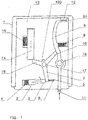
- the overvoltage protection arrangement shown in the figures is based on a housing 1.
- this housing there is a horn spark gap (not shown) with a deion chamber for arc quenching.
- the deion chamber has a multiplicity of spaced-apart quenching plates.
- a trigger electrode (not shown) is located in the ignition area of the horn spark gap.
- a varistor (not shown) is located in the housing 1, which is electrically connected in series with the horn spark gap.
- a first and a second separation device Inside the housing 1 there is a first and a second separation device.
- the first separating device 2 is in a thermally conductive connection with the varistor, not shown.
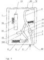
- the slide 3 is released, which is supported by a spring 4 on a guide (see FIG Figure 2 ) is stored.
- the electrical connection between contacts 5 and 6 is closed.
- the slide takes with one of its front edges a first prong 7 of a rotatably mounted star.
- second separating device 13 which has a fusible conductor (not shown). This fusible conductor is located in the area of the deionization chamber (not shown) and can be exposed to an arc that occurs there.
- the fusible conductor of the second separation device 13 holds a spring-force-assisted separation element 14 in a first position.
- the spring force assistance is provided by a third spring 15.
- a related end of the separating element 14 acts on a second prong 16 of the rotatably mounted star.
- the axes of rotation 17 and 18 on the one hand of the star and on the other hand of the lever 8 are at a distance from one another and are parallel to one another.
- overvoltage protection arrangement can be designed as a plug-in part with plug connections 20 and 21.
- a corresponding spring contact 24 rests with a bracket-side end on the contact surface of the gas discharge tube.
- the housing has a first, lower level 26 which accommodates the horn spark gap and the varistor.
- a second, overlying housing level 27 accommodates at least the separating element 14, the star with its star points, the lever 8 and an actuating extension of the slide 3.
- lever 8 is mounted pivotably by means of the axis 18.
- the lever 8 has a bend at a first lever end 81 which releases or covers a display area, an actuating nose for the remote signaling contact 11 being formed on a second lever end 82.
Landscapes
- Engineering & Computer Science (AREA)
- Microelectronics & Electronic Packaging (AREA)
- Physics & Mathematics (AREA)
- Electromagnetism (AREA)
- Fuses (AREA)
- Switch Cases, Indication, And Locking (AREA)
Claims (11)
- Ensemble de protection contre les surtensions, constitué d'un éclateur à cornet situé dans un boîtier isolant (1) et ayant une chambre de déionisation pour l'extinction d'arc, la chambre de déionisation comportant une pluralité de tôles d'extinction espacées et une électrode de déclenchement étant située dans la région d'allumage de l'éclateur à cornet, comprenant en outre une varistance qui est branchée électriquement en série avec l'éclateur à cornet,
caractérisé en ce que
un premier et un deuxième dispositif de déconnexion sont formés dans le boîtier (1),
le premier dispositif de déconnexion (2) est en liaison thermoconductrice avec la varistance et, lorsqu'une température limite est atteinte ou dépassée, libère un curseur (3) qui est soutenu par la force d'un ressort et qui interrompt le branchement en série entre la varistance et l'éclateur à cornet,
le deuxième dispositif de déconnexion (13) comporte en outre un conducteur fusible qui se trouve dans la zone de la chambre de déionisation, le conducteur fusible maintenant dans une première position un élément de déconnexion (14) soutenu par la force d'un ressort et libérant cet élément de déconnexion lors de la fusion induite par une charge, de telle sorte que l'élément de déconnexion (14) occupe une deuxième position, et lorsque la deuxième position est atteinte une connexion électrique avec l'électrode de déclenchement est interrompue,
en outre, une étoile à trois branches montée de manière rotative ou un disque est formé(e) dans le boîtier (1) de telle sorte qu'une première branche d'étoile (7) est entraînée par le curseur (3) lorsque ce dernier se déplace pour interrompre le branchement en série et, de la même manière, une deuxième branche d'étoile (16) est entraînée lorsque l'élément de déconnexion (14) se déplace de la première à la deuxième position,
en résultat du mouvement d'entraînement respectif, l'étoile est soumise à une rotation autour de son axe de rotation, ayant pour conséquence qu'une troisième branche d'étoile (10) libère un levier pivotant (8) soutenu par la force d'un ressort, qui actionne un contact de télécommunication (11) et/ou un affichage optique d'état d'erreur (12). - Ensemble de protection contre les surtensions selon la revendication 1,
caractérisé en ce que
l'électrode de déclenchement est connectée à l'une des électrodes principales de l'éclateur à cornet par un élément limiteur de tension, et cette connexion peut être interrompue au moyen de l'élément de déconnexion (14). - Ensemble de protection contre les surtensions selon la revendication 1 ou 2,
caractérisé en ce que
le boîtier comporte l'éclateur à cornet et la varistance dans un premier plan de boîtier (26), et au moins l'élément de déconnexion (14), l'étoile (100) et le levier (8) ainsi qu'un prolongement d'actionnement du curseur (3) sont formés dans un deuxième plan de boîtier (27). - Ensemble de protection contre les surtensions selon la revendication 2,
caractérisé en ce que
l'élément de déconnexion (14), lorsqu'il atteint la deuxième position, soulève un étrier de contact à ressort (24) d'une surface de contact de l'élément de commutation de tension (22) et interrompt ainsi la connexion électrique. - Ensemble de protection contre les surtensions selon l'une des revendications précédentes,
caractérisé en ce que
le curseur (3) et l'élément de déconnexion (14) sont constitués d'un matériau électriquement isolant. - Ensemble de protection contre les surtensions selon l'une des revendications précédentes,
caractérisé en ce que
le levier (8) est monté de manière pivotante dans le boîtier (1) et présente à une première extrémité de levier (81) une partie coudée qui libère ou recouvre une surface d'affichage, un bec d'actionnement pour le contact de télécommunication (11) étant formé à une deuxième extrémité de levier (82). - Ensemble de protection contre les surtensions selon la revendication 6,
caractérisé en ce que
l'axe de rotation (17) de l'étoile (100) et l'axe de pivotement (18) du levier (8) sont parallèles entre eux. - Ensemble de protection contre les surtensions selon la revendication 7,
caractérisé en ce que
au moins l'axe de rotation (17), l'axe de pivotement (18), l'étoile (100) et le levier (8) sont des composants d'un insert de boîtier qui est situé dans le deuxième plan de boîtier (27). - Ensemble de protection contre les surtensions selon l'une des revendications précédentes,
caractérisé en ce que
il est conçu comme une pièce enfichable avec des contacts enfichables (20 ; 21) pour la réception dans une pièce de base. - Ensemble de protection contre les surtensions selon l'une des revendications précédentes,
caractérisé en ce que
le conducteur fusible est mis en contact avec deux tôles d'extinction espacées de la chambre de déionisation. - Ensemble de protection contre les surtensions selon l'une des revendications 2 à 10,
caractérisé en ce que
l'élément de commutation de tension est réalisé sous forme de dérivateur à gaz (22).
Priority Applications (2)
| Application Number | Priority Date | Filing Date | Title |
|---|---|---|---|
| PL19702435T PL3552282T3 (pl) | 2018-02-27 | 2019-01-30 | Układ ochrony przepięciowej, składający się ze znajdującego się w izolującej obudowie iskiernika rożkowego |
| SI201930024T SI3552282T1 (sl) | 2018-02-27 | 2019-01-30 | Prenapetostna zaščitna razmestitev, ki sestoji iz rogatega iskrišča, ki se nahaja v izoliranem ohišju |
Applications Claiming Priority (3)
| Application Number | Priority Date | Filing Date | Title |
|---|---|---|---|
| DE102018104467 | 2018-02-27 | ||
| DE102018116354.1A DE102018116354A1 (de) | 2018-02-27 | 2018-07-05 | Überspannungsschutzanordnung, bestehend aus einer in einem isolierenden Gehäuse befindlichen Hörnerfunkenstrecke |
| PCT/EP2019/052222 WO2019166170A1 (fr) | 2018-02-27 | 2019-01-30 | Ensemble de protection contre les surtensions constitué d'un éclateur à cornes se trouvant dans un boîtier d'isolation |
Publications (2)
| Publication Number | Publication Date |
|---|---|
| EP3552282A1 EP3552282A1 (fr) | 2019-10-16 |
| EP3552282B1 true EP3552282B1 (fr) | 2020-11-04 |
Family
ID=65084914
Family Applications (1)
| Application Number | Title | Priority Date | Filing Date |
|---|---|---|---|
| EP19702435.9A Active EP3552282B1 (fr) | 2018-02-27 | 2019-01-30 | Ensemble de protection contre les surtensions constitué d'un éclateur à cornes se trouvant dans un boîtier d'isolation |
Country Status (9)
| Country | Link |
|---|---|
| US (1) | US11152769B2 (fr) |
| EP (1) | EP3552282B1 (fr) |
| JP (1) | JP6967658B2 (fr) |
| CN (1) | CN111052521B (fr) |
| DE (2) | DE102018116354A1 (fr) |
| ES (1) | ES2845279T3 (fr) |
| PL (1) | PL3552282T3 (fr) |
| SI (1) | SI3552282T1 (fr) |
| WO (1) | WO2019166170A1 (fr) |
Families Citing this family (10)
| Publication number | Priority date | Publication date | Assignee | Title |
|---|---|---|---|---|
| GB2546492A (en) * | 2016-01-19 | 2017-07-26 | Mpe Ip Ltd | Varistors |
| DE102019101200A1 (de) | 2018-07-04 | 2020-01-09 | Dehn Se + Co Kg | Überspannungsschutzanordnung mit einer in einem isolierenden Gehäuse befindlichen Hörnerfunkenstrecke mit Deionkammer zur Lichtbogenlöschung |
| DE102021102819A1 (de) | 2020-02-26 | 2021-08-26 | Phoenix Contact Gmbh & Co. Kg | Überspannungsschutzvorrichtung |
| DE102020107318B4 (de) | 2020-03-17 | 2023-06-22 | Dehn Se | Überspannungsschutzvorrichtung sowie modulares Überspannungsschutzsystem |
| CN111293006A (zh) * | 2020-03-20 | 2020-06-16 | 贵州泰永长征技术股份有限公司 | 一种断路器的合分状态指示装置 |
| CN113161196B (zh) * | 2020-12-31 | 2022-10-25 | 协讯电子(吉安)有限公司 | 一种线路保护装置 |
| CN114725913A (zh) * | 2021-01-06 | 2022-07-08 | 西门子能源全球有限公司 | 具有用于过电压放电装置的隔离装置的设备 |
| CN114343861B (zh) * | 2022-01-21 | 2023-07-21 | 浙江帝诺医疗科技有限公司 | 一种安全防护的无线电诊断系统的台车 |
| CN114838310A (zh) * | 2022-07-06 | 2022-08-02 | 宝德照明集团有限公司 | 一种防爆led灯 |
| CN115376847B (zh) * | 2022-10-25 | 2023-01-03 | 广东南海电力设计院工程有限公司 | 一种配电网分段器的拉弧自保装置 |
Family Cites Families (21)
| Publication number | Priority date | Publication date | Assignee | Title |
|---|---|---|---|---|
| JP2513859Y2 (ja) * | 1990-04-09 | 1996-10-09 | 日本電気フィールドサービス株式会社 | 保安装置 |
| DE4241311C2 (de) * | 1992-12-08 | 1995-06-08 | Phoenix Contact Gmbh & Co | Temperaturschalter mit einem Bausteingehäuse |
| FR2727806A1 (fr) * | 1994-12-05 | 1996-06-07 | Soule Sa | Dispositif de protection a l'encontre de surtensions transitoires a base de varistances et deconnecteurs thermiques |
| DE19545505C1 (de) | 1995-12-06 | 1997-05-28 | Dehn & Soehne | Überspannungsableiter |
| DE202004006227U1 (de) * | 2004-04-16 | 2004-09-16 | Phoenix Contact Gmbh & Co. Kg | Überspannungsschutzgerät |
| JP4495546B2 (ja) * | 2004-08-18 | 2010-07-07 | 株式会社サンコーシヤ | 保安装置 |
| JP4842004B2 (ja) * | 2006-04-20 | 2011-12-21 | 音羽電機工業株式会社 | 直撃雷用spd |
| DE102006052955B4 (de) * | 2006-09-07 | 2020-07-02 | Dehn Se + Co Kg | Überspannungsableiter mit einem Gehäuse und mit mindestens einem Ableitelement |
| ES2352794T3 (es) * | 2006-09-07 | 2011-02-23 | Dehn + Söhne GmbH + Co KG | Descargador de sobretensiones con una carcasa y con por lo menos un elemento de descarga. |
| DE102009036125A1 (de) * | 2009-08-05 | 2011-02-10 | Phoenix Contact Gmbh & Co. Kg | Überspannungsschutzelement |
| DE102011051738B4 (de) | 2010-08-04 | 2023-05-04 | Dehn Se | Hörnerfunkenstrecken-Blitzstromableiter mit Deionkammer |
| DE102011102937B4 (de) * | 2010-08-17 | 2017-03-02 | DEHN + SÖHNE GmbH + Co. KG. | Anordnung zur Zündung von Funkenstrecken |
| JP5555596B2 (ja) * | 2010-10-08 | 2014-07-23 | 株式会社サンコーシヤ | 保安器 |
| DE102011011254A1 (de) | 2010-12-08 | 2012-06-14 | Dehn + Söhne Gmbh + Co. Kg | Überspannungsableiteranordnung mit mindestens einem Varistorableitelement |
| DE102011018556A1 (de) * | 2011-02-18 | 2012-08-23 | Dehn + Söhne Gmbh + Co. Kg | Überspannungsschutzeinrichtung, umfassend mindestens einen Überspannungsableiter |
| MX355500B (es) * | 2013-02-20 | 2018-04-20 | Emprimus Llc | Proteccion contra voltaje excesivo para sistemas de energia. |
| DE102013021936B3 (de) * | 2013-10-08 | 2015-02-12 | Dehn + Söhne Gmbh + Co. Kg | Kompakte, vorkonfektionierbare Überspannungsschutzvorrichtung |
| DE102013022348B4 (de) | 2013-10-22 | 2016-01-07 | Dehn + Söhne Gmbh + Co. Kg | Überspannungsschutzeinrichtung, aufweisend mindestens einen Überspannungsableiter und eine, mit dem Überspannungsableiter in Reihe geschaltete, thermisch auslösbare Schalteinrichtung |
| DE102014215282B3 (de) | 2014-08-04 | 2015-10-01 | Phoenix Contact Gmbh & Co. Kg | Kombiniertes Überspannungsschutzgerät mit einer integrierten Funkenstrecke |
| DE102014215280B3 (de) * | 2014-08-04 | 2015-09-24 | Phoenix Contact Gmbh & Co. Kg | Kombiniertes Überspannungsschutzgerät mit einer integrierten Funkenstrecke |
| DE102019101200A1 (de) * | 2018-07-04 | 2020-01-09 | Dehn Se + Co Kg | Überspannungsschutzanordnung mit einer in einem isolierenden Gehäuse befindlichen Hörnerfunkenstrecke mit Deionkammer zur Lichtbogenlöschung |
-
2018
- 2018-07-05 DE DE102018116354.1A patent/DE102018116354A1/de not_active Ceased
- 2018-07-05 DE DE202018106960.8U patent/DE202018106960U1/de active Active
-
2019
- 2019-01-30 CN CN201980003998.1A patent/CN111052521B/zh active Active
- 2019-01-30 SI SI201930024T patent/SI3552282T1/sl unknown
- 2019-01-30 US US16/622,611 patent/US11152769B2/en active Active
- 2019-01-30 ES ES19702435T patent/ES2845279T3/es active Active
- 2019-01-30 PL PL19702435T patent/PL3552282T3/pl unknown
- 2019-01-30 JP JP2020505378A patent/JP6967658B2/ja active Active
- 2019-01-30 EP EP19702435.9A patent/EP3552282B1/fr active Active
- 2019-01-30 WO PCT/EP2019/052222 patent/WO2019166170A1/fr not_active Ceased
Also Published As
| Publication number | Publication date |
|---|---|
| SI3552282T1 (sl) | 2021-03-31 |
| EP3552282A1 (fr) | 2019-10-16 |
| DE202018106960U1 (de) | 2019-01-03 |
| US11152769B2 (en) | 2021-10-19 |
| WO2019166170A1 (fr) | 2019-09-06 |
| CN111052521B (zh) | 2021-09-14 |
| ES2845279T3 (es) | 2021-07-26 |
| US20210151957A1 (en) | 2021-05-20 |
| JP6967658B2 (ja) | 2021-11-17 |
| CN111052521A (zh) | 2020-04-21 |
| PL3552282T3 (pl) | 2021-05-31 |
| DE102018116354A1 (de) | 2019-08-29 |
| JP2020537804A (ja) | 2020-12-24 |
Similar Documents
| Publication | Publication Date | Title |
|---|---|---|
| EP3552282B1 (fr) | Ensemble de protection contre les surtensions constitué d'un éclateur à cornes se trouvant dans un boîtier d'isolation | |
| EP1407460B1 (fr) | Coupe-circuit de surtension | |
| EP2826044B1 (fr) | Appareil de protection contre les surtensions | |
| DE102014215280B3 (de) | Kombiniertes Überspannungsschutzgerät mit einer integrierten Funkenstrecke | |
| DE102011102941B4 (de) | Funkenstrecke mit mehreren in Reihe geschalteten, in einer Stapelanordnung befindlichen Einzelfunkenstrecken | |
| EP2319143B1 (fr) | Parafoudre doté d'au moins un élément de dérivation | |
| EP3759773B1 (fr) | Dispositif de protection de surtension doté d'un éclateur à cornes situé dans un boîtier isolant et doté d'une chambre de désionisation pour extinction d'arc | |
| EP2070168B1 (fr) | Parafoudre comportant un boitier et au moins un element d'evacuation | |
| DE102008029670B4 (de) | Überspannungsschutzelement | |
| DE102009053146B3 (de) | Elektrisches Gerät | |
| DE102006052955B4 (de) | Überspannungsableiter mit einem Gehäuse und mit mindestens einem Ableitelement | |
| DE3228471A1 (de) | Ueberspannungsschutzgeraet | |
| DE102015008136B4 (de) | Schalteinrichtung für Überspannungsschutzgeräte | |
| EP2188876B1 (fr) | Dispositif de commutation de limitation des dommages | |
| AT394285B (de) | Geraeteanordnung zum netzanschluss mit einem fehlerstromschutzschalter und mit ueberspannungsableitern | |
| EP2218154B1 (fr) | Dispositif de coupure rapide | |
| EP2801993A1 (fr) | Appareil de commutation doté d'une résistance d'isolation améliorée en cas de déclenchement | |
| DE202009004055U1 (de) | Überspannungsableiter und Überstromschutz | |
| DE102019110006B4 (de) | Überspannungsschutzgerät | |
| EP4176459A1 (fr) | Mécanisme de commutation à ressort compact indépendant de l'opérateur et dispositif de commutation de protection électromécanique | |
| EP2812963B1 (fr) | Parafoudre | |
| EP0104599B1 (fr) | Sectionneur haute tension avec contacts préliminaires | |
| WO2019077038A1 (fr) | Appareil de protection contre les surtensions | |
| WO2013117175A1 (fr) | Dispositif de protection contre les surtensions | |
| EP1098418A2 (fr) | Limiteur de surtension pour réseau de basse tension |
Legal Events
| Date | Code | Title | Description |
|---|---|---|---|
| STAA | Information on the status of an ep patent application or granted ep patent |
Free format text: STATUS: UNKNOWN |
|
| STAA | Information on the status of an ep patent application or granted ep patent |
Free format text: STATUS: THE INTERNATIONAL PUBLICATION HAS BEEN MADE |
|
| PUAI | Public reference made under article 153(3) epc to a published international application that has entered the european phase |
Free format text: ORIGINAL CODE: 0009012 |
|
| STAA | Information on the status of an ep patent application or granted ep patent |
Free format text: STATUS: REQUEST FOR EXAMINATION WAS MADE |
|
| 17P | Request for examination filed |
Effective date: 20190521 |
|
| AK | Designated contracting states |
Kind code of ref document: A1 Designated state(s): AL AT BE BG CH CY CZ DE DK EE ES FI FR GB GR HR HU IE IS IT LI LT LU LV MC MK MT NL NO PL PT RO RS SE SI SK SM TR |
|
| AX | Request for extension of the european patent |
Extension state: BA ME |
|
| GRAP | Despatch of communication of intention to grant a patent |
Free format text: ORIGINAL CODE: EPIDOSNIGR1 |
|
| STAA | Information on the status of an ep patent application or granted ep patent |
Free format text: STATUS: GRANT OF PATENT IS INTENDED |
|
| INTG | Intention to grant announced |
Effective date: 20200707 |
|
| GRAS | Grant fee paid |
Free format text: ORIGINAL CODE: EPIDOSNIGR3 |
|
| GRAA | (expected) grant |
Free format text: ORIGINAL CODE: 0009210 |
|
| STAA | Information on the status of an ep patent application or granted ep patent |
Free format text: STATUS: THE PATENT HAS BEEN GRANTED |
|
| AK | Designated contracting states |
Kind code of ref document: B1 Designated state(s): AL AT BE BG CH CY CZ DE DK EE ES FI FR GB GR HR HU IE IS IT LI LT LU LV MC MK MT NL NO PL PT RO RS SE SI SK SM TR |
|
| DAV | Request for validation of the european patent (deleted) | ||
| DAX | Request for extension of the european patent (deleted) | ||
| REG | Reference to a national code |
Ref country code: GB Ref legal event code: FG4D Free format text: NOT ENGLISH |
|
| REG | Reference to a national code |
Ref country code: CH Ref legal event code: EP |
|
| REG | Reference to a national code |
Ref country code: AT Ref legal event code: REF Ref document number: 1332054 Country of ref document: AT Kind code of ref document: T Effective date: 20201115 |
|
| REG | Reference to a national code |
Ref country code: IE Ref legal event code: FG4D Free format text: LANGUAGE OF EP DOCUMENT: GERMAN |
|
| REG | Reference to a national code |
Ref country code: DE Ref legal event code: R096 Ref document number: 502019000373 Country of ref document: DE |
|
| REG | Reference to a national code |
Ref country code: CH Ref legal event code: NV Representative=s name: HEPP WENGER RYFFEL AG, CH |
|
| REG | Reference to a national code |
Ref country code: NL Ref legal event code: FP |
|
| PG25 | Lapsed in a contracting state [announced via postgrant information from national office to epo] |
Ref country code: GR Free format text: LAPSE BECAUSE OF FAILURE TO SUBMIT A TRANSLATION OF THE DESCRIPTION OR TO PAY THE FEE WITHIN THE PRESCRIBED TIME-LIMIT Effective date: 20210205 Ref country code: NO Free format text: LAPSE BECAUSE OF FAILURE TO SUBMIT A TRANSLATION OF THE DESCRIPTION OR TO PAY THE FEE WITHIN THE PRESCRIBED TIME-LIMIT Effective date: 20210204 Ref country code: FI Free format text: LAPSE BECAUSE OF FAILURE TO SUBMIT A TRANSLATION OF THE DESCRIPTION OR TO PAY THE FEE WITHIN THE PRESCRIBED TIME-LIMIT Effective date: 20201104 Ref country code: PT Free format text: LAPSE BECAUSE OF FAILURE TO SUBMIT A TRANSLATION OF THE DESCRIPTION OR TO PAY THE FEE WITHIN THE PRESCRIBED TIME-LIMIT Effective date: 20210304 Ref country code: RS Free format text: LAPSE BECAUSE OF FAILURE TO SUBMIT A TRANSLATION OF THE DESCRIPTION OR TO PAY THE FEE WITHIN THE PRESCRIBED TIME-LIMIT Effective date: 20201104 |
|
| PGFP | Annual fee paid to national office [announced via postgrant information from national office to epo] |
Ref country code: CZ Payment date: 20210119 Year of fee payment: 3 |
|
| PG25 | Lapsed in a contracting state [announced via postgrant information from national office to epo] |
Ref country code: SE Free format text: LAPSE BECAUSE OF FAILURE TO SUBMIT A TRANSLATION OF THE DESCRIPTION OR TO PAY THE FEE WITHIN THE PRESCRIBED TIME-LIMIT Effective date: 20201104 Ref country code: LV Free format text: LAPSE BECAUSE OF FAILURE TO SUBMIT A TRANSLATION OF THE DESCRIPTION OR TO PAY THE FEE WITHIN THE PRESCRIBED TIME-LIMIT Effective date: 20201104 Ref country code: IS Free format text: LAPSE BECAUSE OF FAILURE TO SUBMIT A TRANSLATION OF THE DESCRIPTION OR TO PAY THE FEE WITHIN THE PRESCRIBED TIME-LIMIT Effective date: 20210304 Ref country code: BG Free format text: LAPSE BECAUSE OF FAILURE TO SUBMIT A TRANSLATION OF THE DESCRIPTION OR TO PAY THE FEE WITHIN THE PRESCRIBED TIME-LIMIT Effective date: 20210204 |
|
| PGFP | Annual fee paid to national office [announced via postgrant information from national office to epo] |
Ref country code: ES Payment date: 20210217 Year of fee payment: 3 Ref country code: SI Payment date: 20210121 Year of fee payment: 3 |
|
| REG | Reference to a national code |
Ref country code: LT Ref legal event code: MG9D |
|
| PG25 | Lapsed in a contracting state [announced via postgrant information from national office to epo] |
Ref country code: HR Free format text: LAPSE BECAUSE OF FAILURE TO SUBMIT A TRANSLATION OF THE DESCRIPTION OR TO PAY THE FEE WITHIN THE PRESCRIBED TIME-LIMIT Effective date: 20201104 |
|
| REG | Reference to a national code |
Ref country code: ES Ref legal event code: FG2A Ref document number: 2845279 Country of ref document: ES Kind code of ref document: T3 Effective date: 20210726 |
|
| PG25 | Lapsed in a contracting state [announced via postgrant information from national office to epo] |
Ref country code: EE Free format text: LAPSE BECAUSE OF FAILURE TO SUBMIT A TRANSLATION OF THE DESCRIPTION OR TO PAY THE FEE WITHIN THE PRESCRIBED TIME-LIMIT Effective date: 20201104 Ref country code: SM Free format text: LAPSE BECAUSE OF FAILURE TO SUBMIT A TRANSLATION OF THE DESCRIPTION OR TO PAY THE FEE WITHIN THE PRESCRIBED TIME-LIMIT Effective date: 20201104 Ref country code: SK Free format text: LAPSE BECAUSE OF FAILURE TO SUBMIT A TRANSLATION OF THE DESCRIPTION OR TO PAY THE FEE WITHIN THE PRESCRIBED TIME-LIMIT Effective date: 20201104 Ref country code: RO Free format text: LAPSE BECAUSE OF FAILURE TO SUBMIT A TRANSLATION OF THE DESCRIPTION OR TO PAY THE FEE WITHIN THE PRESCRIBED TIME-LIMIT Effective date: 20201104 Ref country code: LT Free format text: LAPSE BECAUSE OF FAILURE TO SUBMIT A TRANSLATION OF THE DESCRIPTION OR TO PAY THE FEE WITHIN THE PRESCRIBED TIME-LIMIT Effective date: 20201104 |
|
| REG | Reference to a national code |
Ref country code: DE Ref legal event code: R097 Ref document number: 502019000373 Country of ref document: DE |
|
| PG25 | Lapsed in a contracting state [announced via postgrant information from national office to epo] |
Ref country code: MC Free format text: LAPSE BECAUSE OF FAILURE TO SUBMIT A TRANSLATION OF THE DESCRIPTION OR TO PAY THE FEE WITHIN THE PRESCRIBED TIME-LIMIT Effective date: 20201104 Ref country code: DK Free format text: LAPSE BECAUSE OF FAILURE TO SUBMIT A TRANSLATION OF THE DESCRIPTION OR TO PAY THE FEE WITHIN THE PRESCRIBED TIME-LIMIT Effective date: 20201104 |
|
| PGFP | Annual fee paid to national office [announced via postgrant information from national office to epo] |
Ref country code: PL Payment date: 20210121 Year of fee payment: 3 |
|
| PLBE | No opposition filed within time limit |
Free format text: ORIGINAL CODE: 0009261 |
|
| STAA | Information on the status of an ep patent application or granted ep patent |
Free format text: STATUS: NO OPPOSITION FILED WITHIN TIME LIMIT |
|
| PG25 | Lapsed in a contracting state [announced via postgrant information from national office to epo] |
Ref country code: LU Free format text: LAPSE BECAUSE OF NON-PAYMENT OF DUE FEES Effective date: 20210130 |
|
| REG | Reference to a national code |
Ref country code: BE Ref legal event code: MM Effective date: 20210131 |
|
| 26N | No opposition filed |
Effective date: 20210805 |
|
| PG25 | Lapsed in a contracting state [announced via postgrant information from national office to epo] |
Ref country code: AL Free format text: LAPSE BECAUSE OF FAILURE TO SUBMIT A TRANSLATION OF THE DESCRIPTION OR TO PAY THE FEE WITHIN THE PRESCRIBED TIME-LIMIT Effective date: 20201104 |
|
| PG25 | Lapsed in a contracting state [announced via postgrant information from national office to epo] |
Ref country code: IE Free format text: LAPSE BECAUSE OF NON-PAYMENT OF DUE FEES Effective date: 20210130 |
|
| PG25 | Lapsed in a contracting state [announced via postgrant information from national office to epo] |
Ref country code: BE Free format text: LAPSE BECAUSE OF NON-PAYMENT OF DUE FEES Effective date: 20210131 |
|
| REG | Reference to a national code |
Ref country code: DE Ref legal event code: R081 Ref document number: 502019000373 Country of ref document: DE Owner name: DEHN SE, DE Free format text: FORMER OWNER: DEHN SE + CO KG, 92318 NEUMARKT, DE |
|
| PG25 | Lapsed in a contracting state [announced via postgrant information from national office to epo] |
Ref country code: CZ Free format text: LAPSE BECAUSE OF NON-PAYMENT OF DUE FEES Effective date: 20220130 |
|
| PG25 | Lapsed in a contracting state [announced via postgrant information from national office to epo] |
Ref country code: SI Free format text: LAPSE BECAUSE OF NON-PAYMENT OF DUE FEES Effective date: 20220131 |
|
| REG | Reference to a national code |
Ref country code: SI Ref legal event code: KO00 Effective date: 20220929 |
|
| REG | Reference to a national code |
Ref country code: ES Ref legal event code: FD2A Effective date: 20230224 |
|
| PG25 | Lapsed in a contracting state [announced via postgrant information from national office to epo] |
Ref country code: ES Free format text: LAPSE BECAUSE OF NON-PAYMENT OF DUE FEES Effective date: 20220131 |
|
| PG25 | Lapsed in a contracting state [announced via postgrant information from national office to epo] |
Ref country code: CY Free format text: LAPSE BECAUSE OF FAILURE TO SUBMIT A TRANSLATION OF THE DESCRIPTION OR TO PAY THE FEE WITHIN THE PRESCRIBED TIME-LIMIT Effective date: 20201104 |
|
| PG25 | Lapsed in a contracting state [announced via postgrant information from national office to epo] |
Ref country code: HU Free format text: LAPSE BECAUSE OF FAILURE TO SUBMIT A TRANSLATION OF THE DESCRIPTION OR TO PAY THE FEE WITHIN THE PRESCRIBED TIME-LIMIT; INVALID AB INITIO Effective date: 20190130 |
|
| REG | Reference to a national code |
Ref country code: NL Ref legal event code: PD Owner name: DEHN SE; DE Free format text: DETAILS ASSIGNMENT: CHANGE OF OWNER(S), ASSIGNMENT; FORMER OWNER NAME: DEHN SE + CO KG Effective date: 20230821 Ref country code: GB Ref legal event code: 732E Free format text: REGISTERED BETWEEN 20230727 AND 20230802 |
|
| REG | Reference to a national code |
Ref country code: AT Ref legal event code: PC Ref document number: 1332054 Country of ref document: AT Kind code of ref document: T Owner name: DEHN SE, DE Effective date: 20230822 |
|
| PG25 | Lapsed in a contracting state [announced via postgrant information from national office to epo] |
Ref country code: MK Free format text: LAPSE BECAUSE OF FAILURE TO SUBMIT A TRANSLATION OF THE DESCRIPTION OR TO PAY THE FEE WITHIN THE PRESCRIBED TIME-LIMIT Effective date: 20201104 |
|
| PG25 | Lapsed in a contracting state [announced via postgrant information from national office to epo] |
Ref country code: PL Free format text: LAPSE BECAUSE OF NON-PAYMENT OF DUE FEES Effective date: 20220130 |
|
| PG25 | Lapsed in a contracting state [announced via postgrant information from national office to epo] |
Ref country code: TR Free format text: LAPSE BECAUSE OF FAILURE TO SUBMIT A TRANSLATION OF THE DESCRIPTION OR TO PAY THE FEE WITHIN THE PRESCRIBED TIME-LIMIT Effective date: 20201104 |
|
| PG25 | Lapsed in a contracting state [announced via postgrant information from national office to epo] |
Ref country code: MT Free format text: LAPSE BECAUSE OF FAILURE TO SUBMIT A TRANSLATION OF THE DESCRIPTION OR TO PAY THE FEE WITHIN THE PRESCRIBED TIME-LIMIT Effective date: 20201104 |
|
| PGFP | Annual fee paid to national office [announced via postgrant information from national office to epo] |
Ref country code: NL Payment date: 20250122 Year of fee payment: 7 |
|
| PGFP | Annual fee paid to national office [announced via postgrant information from national office to epo] |
Ref country code: DE Payment date: 20250120 Year of fee payment: 7 |
|
| PGFP | Annual fee paid to national office [announced via postgrant information from national office to epo] |
Ref country code: AT Payment date: 20250120 Year of fee payment: 7 Ref country code: CH Payment date: 20250201 Year of fee payment: 7 |
|
| PGFP | Annual fee paid to national office [announced via postgrant information from national office to epo] |
Ref country code: FR Payment date: 20250128 Year of fee payment: 7 |
|
| PGFP | Annual fee paid to national office [announced via postgrant information from national office to epo] |
Ref country code: IT Payment date: 20250131 Year of fee payment: 7 Ref country code: GB Payment date: 20250123 Year of fee payment: 7 |