EP3552282B1 - Überspannungsschutzanordnung, bestehend aus einer in einem isolierenden gehäuse befindlichen hörnerfunkenstrecke - Google Patents
Überspannungsschutzanordnung, bestehend aus einer in einem isolierenden gehäuse befindlichen hörnerfunkenstrecke Download PDFInfo
- Publication number
- EP3552282B1 EP3552282B1 EP19702435.9A EP19702435A EP3552282B1 EP 3552282 B1 EP3552282 B1 EP 3552282B1 EP 19702435 A EP19702435 A EP 19702435A EP 3552282 B1 EP3552282 B1 EP 3552282B1
- Authority
- EP
- European Patent Office
- Prior art keywords
- overvoltage protection
- protection arrangement
- housing
- star
- spark gap
- Prior art date
- Legal status (The legal status is an assumption and is not a legal conclusion. Google has not performed a legal analysis and makes no representation as to the accuracy of the status listed.)
- Active
Links
Images


Classifications
-
- H—ELECTRICITY
- H01—ELECTRIC ELEMENTS
- H01T—SPARK GAPS; OVERVOLTAGE ARRESTERS USING SPARK GAPS; SPARKING PLUGS; CORONA DEVICES; GENERATING IONS TO BE INTRODUCED INTO NON-ENCLOSED GASES
- H01T1/00—Details of spark gaps
- H01T1/14—Means structurally associated with spark gap for protecting it against overload or for disconnecting it in case of failure
-
- H—ELECTRICITY
- H01—ELECTRIC ELEMENTS
- H01T—SPARK GAPS; OVERVOLTAGE ARRESTERS USING SPARK GAPS; SPARKING PLUGS; CORONA DEVICES; GENERATING IONS TO BE INTRODUCED INTO NON-ENCLOSED GASES
- H01T4/00—Overvoltage arresters using spark gaps
- H01T4/10—Overvoltage arresters using spark gaps having a single gap or a plurality of gaps in parallel
- H01T4/14—Arcing horns
-
- H—ELECTRICITY
- H01—ELECTRIC ELEMENTS
- H01C—RESISTORS
- H01C7/00—Non-adjustable resistors formed as one or more layers or coatings; Non-adjustable resistors made from powdered conducting material or powdered semi-conducting material with or without insulating material
- H01C7/10—Non-adjustable resistors formed as one or more layers or coatings; Non-adjustable resistors made from powdered conducting material or powdered semi-conducting material with or without insulating material voltage responsive, i.e. varistors
- H01C7/12—Overvoltage protection resistors; Arresters
- H01C7/126—Means for protecting against excessive pressure or for disconnecting in case of failure
-
- H—ELECTRICITY
- H01—ELECTRIC ELEMENTS
- H01H—ELECTRIC SWITCHES; RELAYS; SELECTORS; EMERGENCY PROTECTIVE DEVICES
- H01H85/00—Protective devices in which the current flows through a part of fusible material and this current is interrupted by displacement of the fusible material when this current becomes excessive
- H01H85/02—Details
- H01H85/04—Fuses, i.e. expendable parts of the protective device, e.g. cartridges
- H01H85/05—Component parts thereof
- H01H85/165—Casings
-
- H—ELECTRICITY
- H01—ELECTRIC ELEMENTS
- H01H—ELECTRIC SWITCHES; RELAYS; SELECTORS; EMERGENCY PROTECTIVE DEVICES
- H01H85/00—Protective devices in which the current flows through a part of fusible material and this current is interrupted by displacement of the fusible material when this current becomes excessive
- H01H85/02—Details
- H01H85/44—Structural association with a spark-gap arrester
-
- H—ELECTRICITY
- H01—ELECTRIC ELEMENTS
- H01T—SPARK GAPS; OVERVOLTAGE ARRESTERS USING SPARK GAPS; SPARKING PLUGS; CORONA DEVICES; GENERATING IONS TO BE INTRODUCED INTO NON-ENCLOSED GASES
- H01T1/00—Details of spark gaps
- H01T1/02—Means for extinguishing arc
-
- H—ELECTRICITY
- H01—ELECTRIC ELEMENTS
- H01T—SPARK GAPS; OVERVOLTAGE ARRESTERS USING SPARK GAPS; SPARKING PLUGS; CORONA DEVICES; GENERATING IONS TO BE INTRODUCED INTO NON-ENCLOSED GASES
- H01T1/00—Details of spark gaps
- H01T1/16—Series resistor structurally associated with spark gap
-
- H—ELECTRICITY
- H01—ELECTRIC ELEMENTS
- H01T—SPARK GAPS; OVERVOLTAGE ARRESTERS USING SPARK GAPS; SPARKING PLUGS; CORONA DEVICES; GENERATING IONS TO BE INTRODUCED INTO NON-ENCLOSED GASES
- H01T2/00—Spark gaps comprising auxiliary triggering means
- H01T2/02—Spark gaps comprising auxiliary triggering means comprising a trigger electrode or an auxiliary spark gap
-
- H—ELECTRICITY
- H01—ELECTRIC ELEMENTS
- H01T—SPARK GAPS; OVERVOLTAGE ARRESTERS USING SPARK GAPS; SPARKING PLUGS; CORONA DEVICES; GENERATING IONS TO BE INTRODUCED INTO NON-ENCLOSED GASES
- H01T4/00—Overvoltage arresters using spark gaps
- H01T4/04—Housings
-
- H—ELECTRICITY
- H01—ELECTRIC ELEMENTS
- H01H—ELECTRIC SWITCHES; RELAYS; SELECTORS; EMERGENCY PROTECTIVE DEVICES
- H01H37/00—Thermally-actuated switches
- H01H37/74—Switches in which only the opening movement or only the closing movement of a contact is effected by heating or cooling
- H01H37/76—Contact member actuated by melting of fusible material, actuated due to burning of combustible material or due to explosion of explosive material
- H01H37/761—Contact member actuated by melting of fusible material, actuated due to burning of combustible material or due to explosion of explosive material with a fusible element forming part of the switched circuit
- H01H2037/762—Contact member actuated by melting of fusible material, actuated due to burning of combustible material or due to explosion of explosive material with a fusible element forming part of the switched circuit using a spring for opening the circuit when the fusible element melts
- H01H2037/763—Contact member actuated by melting of fusible material, actuated due to burning of combustible material or due to explosion of explosive material with a fusible element forming part of the switched circuit using a spring for opening the circuit when the fusible element melts the spring being a blade spring
-
- H—ELECTRICITY
- H01—ELECTRIC ELEMENTS
- H01H—ELECTRIC SWITCHES; RELAYS; SELECTORS; EMERGENCY PROTECTIVE DEVICES
- H01H85/00—Protective devices in which the current flows through a part of fusible material and this current is interrupted by displacement of the fusible material when this current becomes excessive
- H01H85/02—Details
- H01H85/04—Fuses, i.e. expendable parts of the protective device, e.g. cartridges
- H01H85/041—Fuses, i.e. expendable parts of the protective device, e.g. cartridges characterised by the type
- H01H85/048—Fuse resistors
- H01H2085/0486—Fuse resistors with voltage dependent resistor, e.g. varistor
Definitions
- the invention is based on an overvoltage protection arrangement, consisting of a horn spark gap located in an insulating housing with a deion chamber for arc quenching, the deion chamber having a large number of spaced arcing plates and a trigger electrode located in the ignition area of the horn spark gap, furthermore with a varistor, which connects to the horn spark gap is electrically connected in series, according to the preamble of claim 1.
- Horn spark gap lightning arresters with deion chambers for arc extinguishing are for example from the DE 10 2011 051 738 A1 previously known.
- a corresponding horn spark gap is located in a housing and has means for controlling the internal gas flow in order to set a different behavior of the arc arising from a pulse current load on the one hand and the arc caused by the line follow current on the other.
- a trigger electrode can be arranged in the ignition area.
- This trigger electrode can comprise a conductive element which is surrounded by a sliding path. Adjacent sliding sections can also consist of an insulating or semiconducting material.
- the known trigger electrode is either used on one of the two electrodes in the ignition area or is preferably arranged between the two electrodes of the horn spark gap in the lower area of the ignition area.
- the DE 195 45 505 C1 shows a surge arrester with at least one voltage-dependent resistor, for example a varistor, and thermal shutdown devices.
- These disconnection devices consist on the one hand of a fuse strip and on the other hand of a thermal release with a eutectic melt alloy.
- a housing in which a surge-proof fuse strip is located.
- the damage indicator is a separate component which is detachably fastened to the housing and can be moved relative to the fuse housing after a spring has been released.
- the thermal release is arranged outside the housing and is in a thermally conductive connection with the varistor in such a way that inadmissible heating of the varistor causes the thermal release to be disconnected and the damage is indicated.
- the spark gap has a series-connected fuse, the series circuit being connectable to a supply network with a first potential and a second potential different therefrom.
- the spark gap has two main electrodes. There is also a housing.
- the fusible conductor connects a first connection to the second main electrode of the spark gap, the fuse also having a further contact, the further contact being arranged insulated from the first contact and insulated from the second main electrode of the spark gap.
- the overvoltage protection device has a plasma channel from leads the combustion chamber of the spark gap into the vicinity of the fusible conductor in such a way that plasma can have a targeted degrading effect on the fusible wire. As a result, the fuse wire can be destroyed.
- the disconnection device serves to disconnect the varistor discharge element from the network, the disconnection device being integrated into the electrical connection path of the discharge conductor arrangement.
- the disconnection device comprises a device which switches a fuse into the electrical connection path in the event of a thermal overload of the varistor discharge element.
- the surge arrester arrangement is thus able to reduce the short-circuit current of the connected power supply or the connected network in the overload short-circuit state inside the varistor discharge element. Consequential damage to connected devices and / or internal connections can be reduced.
- a further developed overvoltage protection arrangement consisting of a horn spark gap located in an insulating housing with a deion chamber for arc quenching, which creates the possibility of all conceivable faults, i.e. if the thermal load is too high used varistors but also in the event of marginal arcs occurring within the deionization chamber to cause a shutdown, with each error state that has occurred, regardless of its cause or type, can be symbolized with a single display device and optionally reported remotely.
- an overvoltage protection arrangement consisting of a horn spark gap with a deion chamber for arc quenching located in an insulating housing is assumed.
- the deion chamber has a plurality of spaced-apart quenching plates, as shown for example in the DE 10 2011 051 738 A1 is shown.
- a trigger electrode is located in the ignition area of the horn spark gap in order to make the response behavior of the spark gap adjustable. Furthermore, the overvoltage protection arrangement comprises a varistor, which is electrically connected in series with the horn spark gap.
- a housing for accommodating the surge protection arrangement is designed, which accommodates a first and a second disconnection device.
- the first disconnection device is in a thermally conductive connection with the varistor.
- a spring force-assisted slide is released, which interrupts the series connection between the varistor and the horn spark gap.
- This thermal separation device can for example comprise a soldering point which changes its physical state when the melting temperature is reached, so that the mentioned slide is able to execute the desired movement with the aid of the spring force support.
- a second separating device which has a fusible conductor which is located in the area of the deionization chamber and can be exposed to an arc that occurs there.
- the fusible conductor is in contact with extinguishing plates of the deionization chamber and melts when loaded, in particular when there is a line follow current load.
- the fusible conductor is able to hold a spring force-assisted separating element in a first position, but also to release this separating element in the event of melting due to the effect of an arc, such that the separating element assumes a second position.
- an electrical connection to the trigger electrode is interrupted. It is no longer possible to re-ignite the spark gap due to the overload that has occurred.
- a three-pronged, rotatably mounted star or a circular disc with lugs is formed in the housing in such a way that a first star spike or lug with a star spike end is carried along by the slide when it is moved to interrupt the series connection.
- a second star point or nose with its star point end can be taken along when the separating element moves from the first to the second position, with the star or the disk being subject to a rotation about its axis of rotation as a result of the respective entrainment movement.
- the result is that a third star point or nose with its star point end releases a spring-force-supported, pivotable lever which actuates a remote signaling contact and / or an optical fault status indicator.
- the respective state of the respective separating device can be scanned, along with a mechanical movement, so that the aforementioned lever is released from its position fixed by the third star point.
- the trigger electrode is connected to one of the main electrodes of the horn spark gap via a voltage-limiting element.
- This aforementioned connection can be electrically interrupted by means of the isolating slide.
- the housing has the horn spark gap and the varistor in a first housing level, with at least the separating element, the star and the lever as well as an actuation extension of the slide being formed in a second housing level.
- the slide arrives in such a position that two metallic contacts are separated, the slide penetrating into the separating space and thereby preventing possible arcs.
- the separating element When the second position is reached, the separating element lifts a spring contact clip from a contact surface of the voltage-switching element, so that the desired interruption of the electrical connection can thereby be achieved.
- Both the slide and the separating element consist of an electrically insulating material.
- the status display lever is pivotably mounted in the housing and has an angled portion at a first end of the lever which exposes or covers a display surface, with an actuating nose for the remote signaling contact being formed on a second end of the lever.
- the display area can here preferably be a housing area or a window in the housing.
- the axis of rotation of the star or the disk and the pivot axis of the lever are preferably parallel to one another and are spaced apart such that the third prong of the star can be moved from a stop position relative to the lever into a release position when the star is rotated.
- At least the axis of rotation, the pivot axis, the star and the lever are components of a housing insert part which is located in the second housing plane.
- This housing insert forms a partition in relation to a housing level below, in which the horn spark gap and the varistor are located.
- the overvoltage protection arrangement can be designed as a plug-in part with plug-in contacts for reception in a base part.
- the plug contacts are preferably located on an underside of the plug part.
- side surfaces of the plug-in part can have latching elements for fixing the plug-in part in the base part also have means for locking or unlocking these latching elements and for easier pulling of the plug-in part from the base part.
- the fusible conductor of the second separation device is in contact with selected two spaced-apart quenching plates.
- the voltage-limiting element is preferably designed as a gas discharge tube.
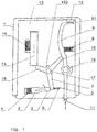
- the overvoltage protection arrangement shown in the figures is based on a housing 1.
- this housing there is a horn spark gap (not shown) with a deion chamber for arc quenching.
- the deion chamber has a multiplicity of spaced-apart quenching plates.
- a trigger electrode (not shown) is located in the ignition area of the horn spark gap.
- a varistor (not shown) is located in the housing 1, which is electrically connected in series with the horn spark gap.
- a first and a second separation device Inside the housing 1 there is a first and a second separation device.
- the first separating device 2 is in a thermally conductive connection with the varistor, not shown.
- the slide 3 is released, which is supported by a spring 4 on a guide (see FIG Figure 2 ) is stored.
- the electrical connection between contacts 5 and 6 is closed.
- the slide takes with one of its front edges a first prong 7 of a rotatably mounted star.
- second separating device 13 which has a fusible conductor (not shown). This fusible conductor is located in the area of the deionization chamber (not shown) and can be exposed to an arc that occurs there.
- the fusible conductor of the second separation device 13 holds a spring-force-assisted separation element 14 in a first position.
- the spring force assistance is provided by a third spring 15.
- a related end of the separating element 14 acts on a second prong 16 of the rotatably mounted star.
- the axes of rotation 17 and 18 on the one hand of the star and on the other hand of the lever 8 are at a distance from one another and are parallel to one another.
- overvoltage protection arrangement can be designed as a plug-in part with plug connections 20 and 21.
- a corresponding spring contact 24 rests with a bracket-side end on the contact surface of the gas discharge tube.
- the housing has a first, lower level 26 which accommodates the horn spark gap and the varistor.
- a second, overlying housing level 27 accommodates at least the separating element 14, the star with its star points, the lever 8 and an actuating extension of the slide 3.
- lever 8 is mounted pivotably by means of the axis 18.
- the lever 8 has a bend at a first lever end 81 which releases or covers a display area, an actuating nose for the remote signaling contact 11 being formed on a second lever end 82.
Landscapes
- Engineering & Computer Science (AREA)
- Microelectronics & Electronic Packaging (AREA)
- Physics & Mathematics (AREA)
- Electromagnetism (AREA)
- Fuses (AREA)
- Switch Cases, Indication, And Locking (AREA)
Description
- Die Erfindung geht aus von einer Überspannungsschutzanordnung, bestehend aus einer in einem isolierenden Gehäuse befindlichen Hörnerfunkenstrecke mit Deionkammer zur Lichtbogenlöschung, wobei die Deionkammer eine Vielzahl von beabstandeten Löschblechen aufweist und im Zündbereich der Hörnerfunkenstrecke eine Triggerelektrode befindlich ist, weiterhin mit einem Varistor, welcher mit der Hörnerfunkenstrecke elektrisch in Reihe geschalten ist, gemäß Oberbegriff des Anspruches 1.
- Hörnerfunkenstrecken-Blitzstromableiter mit Deionkammer zur Lichtbogenlöschung sind beispielsweise aus der
DE 10 2011 051 738 A1 vorbekannt. - Eine entsprechende Hörnerfunkenstrecke befindet sich in einem Gehäuse und weist Mittel zur Steuerung der internen Gasströmung zur Einstellung eines unterschiedlichen Verhaltens des bei einer Impulsstrombelastung entstehenden Lichtbogens einerseits sowie des Netzfolgestrom-bedingten Lichtbogens andererseits auf.
- Bei einer derartigen Hörnerfunkenstrecke ist im Zündbereich eine Triggerelektrode anordenbar. Diese Triggerelektrode kann ein leitfähiges Element umfassen, welches von einer Gleitstrecke umgeben ist. Ebenso können benachbarte Gleitstrecken aus einem isolierenden oder halbleitenden Material bestehen. Die bekannte Triggerelektrode ist entweder an einer der beiden Elektroden im Zündbereich eingesetzt oder zwischen den beiden Elektroden der Hörnerfunkenstrecke bevorzugt im unteren Bereich des Zündbereiches angeordnet. Die
DE 195 45 505 C1 zeigt einen Überspannungsableiter mit mindestens einem spannungsabhängigen Widerstand, zum Beispiel einem Varistor, und thermischen Abschaltvorrichtungen. - Diese Abschaltvorrichtungen bestehen einerseits aus einem Sicherungsstreifen sowie andererseits aus einer Thermoauslösung mit eutektischer Schmelzlegierung.
- Mit dem Auftrennen des Sicherungsstreifens oder der Thermosicherung wird mit Hilfe einer Federkraft ein Schadensanzeiger betätigt. Ein Schadensfall ist damit sichtbar.
- Um sowohl im Falle eines durch Alterung entstehenden unzulässigen Leckstromes des Varistors als auch im Falle eines zu hohen, einen Kurzschluss im Varistor erzeugenden Stoßstromes mit einfachen Mitteln in raumsparender Bauweise für eine Anzeige des eingetretenen Fehlerfalles zu sorgen, ist ein Gehäuse vorgesehen, in dem sich ein stoßstromfester Sicherungsstreifen befindet. Der Schadensanzeiger ist ein gesonderter, am Gehäuse lösbar befestigter und nach Lösung einer Feder relativ zum Sicherungsgehäuse bewegbarer Bauteil.
- Die Thermoauslösung ist außerhalb des Gehäuses angeordnet und steht mit dem Varistor in einer wärmeleitenden Verbindung, derart, dass eine unzulässige Erwärmung des Varistors die Auftrennung der Thermoauslösung bewirkt und die Schadensanzeige erfolgt.
- Aus der
DE 10 2014 215 282 B3 ist ein kombiniertes Überspannungsschutzgerät mit einer integrierten Funkenstrecke vorbekannt. Die Funkenstrecke weist eine in Reihe geschaltete Schmelzsicherung auf, wobei die Reihenschaltung an ein Versorgungsnetz mit einem ersten Potential und einem hiervon verschiedenen zweiten Potential anschließbar ist. Die Funkenstrecke weist zwei Hauptelektroden auf. Weiterhin ist ein Gehäuse vorhanden. - Der Schmelzleiter verbindet einen ersten Anschluss mit der zweiten Hauptelektrode der Funkenstrecke, wobei die Schmelzsicherung weiterhin einen weiteren Kontakt aufweist, wobei der weitere Kontakt isoliert zum ersten Kontakt und isoliert zur zweiten Hauptelektrode der Funkenstrecke angeordnet ist. Das Überspannungsschutzgerät weist einen Plasmakanal auf, der aus dem Brennraum der Funkenstrecke so in die Nachbarschaft des Schmelzleiters führt, dass Plasma auf den Schmelzdraht gezielt degradierend einwirken kann. Infolgedessen kann der Schmelzdraht einer Zerstörung unterliegen.
- Bei dem Überspannungsableiter mit mindestens einem Varistorelement sowie einer Abtrennvorrichtung nach
DE 10 2011 011 254 A1 dient die Abtrenneinrichtung dazu, das Varistorableitelement vom Netz zu trennen, wobei die Abtrennvorrichtung in den elektrischen Anschlusspfad der Ableiteranordnung eingebunden ist. - Die Abtrennvorrichtung umfasst eine Einrichtung, welche im thermischen Überlastfall des Varistorableitelementes eine Sicherung in den elektrischen Anschlusspfad schaltet. Damit ist die Überspannungsableiteranordnung in der Lage, im Überlastungs-Kurzschlusszustand im Inneren des Varistorableitelementes den Kurzschlussstrom der angeschlossenen Stromversorgung bzw. des angeschlossenen Netzes zu reduzieren. Folgeschäden angeschlossener Geräte und/oder interner Verbindungen können reduziert werden.
- Ausgehend vom geschilderten Stand der Technik ist es Aufgabe der Erfindung, eine weiterentwickelte Überspannungsschutzanordnung, bestehend aus einer in einem isolierenden Gehäuse befindlichen Hörnerfunkenstrecke mit Deionkammer zur Lichtbogenlöschung anzugeben, welche die Möglichkeit schafft, bei allen denkbaren auftretenden Fehlerfällen, das heißt bei zu hoher thermischer Belastung des eingesetzten Varistors aber auch bei auftretenden grenzwertigen Lichtbögen innerhalb der Deionkammer ein Abschalten zu bewirken, wobei jeder eingetretene Fehlerzustand unabhängig von seiner Ursache oder Art mit einer einzigen Anzeigeeinrichtung symbolisiert und gegebenenfalls ferngemeldet werden kann.
- Die Lösung der Aufgabe der Erfindung erfolgt mit der Merkmalskombination nach der Lehre des Patentanspruches 1, wobei die Unteransprüche mindestens zweckmäßige Ausgestaltungen und Weiterbildungen umfassen.
- Es wird demnach von einer Überspannungsschutzanordnung bestehend aus einer in einem isolierenden Gehäuse befindlichen Hörnerfunkenstrecke mit Deionkammer zur Lichtbogenlöschung ausgegangen. Die Deionkammer weist eine Vielzahl von beabstandeten Löschblechen auf, wie dies beispielsweise in der
DE 10 2011 051 738 A1 gezeigt ist. - Im Zündbereich der Hörnerfunkenstrecke ist eine Triggerelektrode befindlich, um das Ansprechverhalten der Funkenstrecke einstellbar zu gestalten. Weiterhin umfasst die Überspannungsschutzanordnung einen Varistor, welcher mit der Hörnerfunkenstrecke elektrisch in Reihe geschalten ist.
- Erfindungsgemäß ist ein Gehäuse zur Aufnahme der Überspannungsschutzanordnung ausgebildet, das eine erste und eine zweite Abtrennvorrichtung aufnimmt.
- Die erste Abtrennvorrichtung steht in wärmeleitender Verbindung mit dem Varistor. Beim Erreichen oder Überschreiten einer Grenztemperatur wird ein federkraftunterstützter Schieber freigegeben, welcher die Reihenschaltung zwischen Varistor und Hörnerfunkenstrecke unterbricht. Diese thermische Abtrennvorrichtung kann beispielsweise eine Lötstelle umfassen, welche mit Erreichen der Schmelztemperatur ihren Aggregatzustand ändert, so dass der erwähnte Schieber unter Zuhilfenahme der Federkraftunterstützung in der Lage ist, die gewünschte Bewegung auszuführen.
- Weiterhin ist eine zweite Abtrennvorrichtung vorhanden, die einen Schmelzleiter aufweist, welcher im Bereich der Deionkammer befindlich und dort einem entstehenden Lichtbogen ausgesetzt sein kann. In einer Ausführungsform ist der Schmelzleiter mit Löschblechen der Deionkammer kontaktiert und schmilzt bei Belastung, insbesondere bei einer Netzfolgestrombelastung.
- Der Schmelzleiter ist in der Lage, ein federkraftunterstütztes Abtrennelement in einer ersten Position zu halten, aber auch dieses Abtrennelement bei lichtbogeneinwirkungsbedingtem Schmelzen freizugeben, derart, dass das Abtrennelement eine zweite Position einnimmt. Wenn die zweite Position erreicht wurde, wird eine elektrische Verbindung zur Triggerelektrode unterbrochen. Ein erneutes Zünden der Funkenstrecke ist infolge der eingetretenen Überlastung nicht mehr möglich.
- Weiterhin ist im Gehäuse ein dreizackiger, drehbar gelagerter Stern oder eine Kreisscheibe mit Nasen so ausgebildet, dass eine erste Sternzacke oder Nase mit einem Sternzackenende vom Schieber bei dessen Bewegung zum Unterbrechen der Reihenschaltung mitgenommen wird.
- In gleicher Weise ist eine zweite Sternzacke oder Nase mit ihrem Sternzackenende bei Bewegung des Abtrennelementes von der ersten in die zweite Position mitnehmbar, wobei im Ergebnis der jeweiligen Mitnahmebewegung der Stern oder die Scheibe einer Verdrehung um seine Drehachse unterliegt. Die Folge ist, dass eine dritte Sternzacke oder Nase mit ihrem Sternzackenende einen federkraftunterstützten, verschwenkbaren Hebel freigibt, welcher einen Fernmeldekontakt und/oder eine optische Fehlerzustandsanzeige betätigt.
- Die jeweilige Einwirkung entweder des Schiebers oder des Abtrennelementes auf den drehbar gelagerten Stern mit der Folge der dann eintretenden Verdrehung des Sterns nebst Auslösen des verschwenkbaren Hebels entspricht einer quasi mechanischen "ODER"-Verknüpfung hinsichtlich der Abtrennvorrichtungen.
- Erfindungsgemäß kann durch Einsatz des drehbar gelagerten Sterns oder der Kreisscheibe auf engstem Raum das Abtasten des jeweiligen Zustandes der betreffenden Abtrennvorrichtung erfolgen nebst Weitergabe einer mechanischen Bewegung derart, dass der vorerwähnte Hebel aus seiner durch die dritte Sternzacke fixierten Position freigegeben wird.
- In Ausgestaltung der Erfindung ist die Triggerelektrode über ein spannungsbegrenzendes Element mit einer der Hauptelektroden der Hörnerfunkenstrecke in Verbindung stehend. Diese vorgenannte Verbindung ist mittels des Abtrennschiebers elektrisch unterbrechbar.
- Das Gehäuse weist in einer ersten Gehäuseebene die Hörnerfunkenstrecke und den Varistor auf, wobei in einer zweiten Gehäuseebene mindestens das Abtrennelement, der Stern und der Hebel sowie ein Betätigungsfortsatz des Schiebers ausgebildet sind.
- Der Schieber gelangt im Ergebnis der Abtrennbewegung in eine solche Position, dass zwei metallische Kontakte getrennt werden, wobei der Schieber in den Trennungszwischenraum eindringt und hierdurch möglicherweise entstehende Lichtbögen verhindert werden.
- Das Abtrennelement hebt mit dem Erreichen der zweiten Position einen Federkontaktbügel von einer Kontaktfläche des spannungsschaltenden Elementes ab, so dass hierdurch die gewünschte Unterbrechung der elektrischen Verbindung realisierbar ist.
- Sowohl der Schieber als auch das Abtrennelement bestehen aus einem elektrisch isolierenden Material.
- Der Hebel zur Zustandsanzeige ist verschwenkbar im Gehäuse gelagert und weist an einem ersten Hebelende eine Abwinkelung auf, welche eine Anzeigefläche freigibt oder abdeckt, wobei an einem zweiten Hebelende eine Betätigungsnase für den Fernmeldekontakt ausgebildet ist.
- Die Anzeigefläche kann hierbei bevorzugt eine Gehäusefläche oder ein Fenster im Gehäuse sein.
- Die Drehachse des Sterns oder der Scheibe und die Schwenkachse des Hebels liegen bevorzugt parallel zueinander und weisen einen solchen Abstand auf, dass die dritte Zacke des Sterns bei Verdrehung des Sterns von einer Anschlagposition bezogen auf den Hebel in eine Freigabeposition überführbar ist.
- Mindestens die Drehachse, die Schwenkachse, der Stern und der Hebel sind Bestandteile eines Gehäuseeinsatzteiles, welches in der zweiten Gehäuseebene befindlich ist. Dieses Gehäuseeinsatzteil bildet eine Zwischenwand bezogen auf eine darunterliegende Gehäuseebene, in der sich die Hörnerfunkenstrecke und der Varistor befindet.
- Die Überspannungsschutzanordnung kann als Steckteil mit Steckkontakten zur Aufnahme in einem Basisteil ausgebildet werden. Die Steckkontakte befinden sich dabei bevorzugt an einer Unterseite des Steckteiles. Seitenflächen des Steckteiles können Rastelemente zum Fixieren des Steckteiles im Basisteil aber auch Mittel zum Arretieren bzw. Entarretieren dieser Rastelemente sowie zum leichteren Ziehen des Steckteiles aus dem Basisteil aufweisen.
- In einer bevorzugten Ausführungsform der Erfindung ist der Schmelzleiter der zweiten Abtrennvorrichtung mit ausgewählten zwei beabstandeten Löschblechen kontaktiert.
- Das spannungsbegrenzende Element ist bevorzugt als Gasableiter ausgebildet.
- Die Erfindung soll nachstehend anhand eines Ausführungsbeispieles sowie unter Zuhilfenahme von Figuren näher erläutert werden.
- Hierbei zeigen:
- Fig. 1
- eine Prinzipdarstellung einer Überspannungsschutzanordnung mit dargestellter erster und zweiter Abtrennvorrichtung nebst Drehstern und Hebelfunktionsanzeige in einem Zustand der vollständigen Funktion der eingesetzten Überspannungsableiter, insbesondere einer Hörnerfunkenstrecke und einem Varistor;
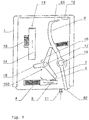
- Fig. 2
- eine Darstellung ähnlich derjenigen nach
Fig. 1 , jedoch im Zustand der ausgelösten ersten Abtrennvorrichtung mit Schieber und hierdurch resultierender Drehbewegung des Sterns nebst Freigabe des Hebels für die Federanzeige; - Fig. 3
- eine Darstellung ähnlich derjenigen nach
Fig. 2 , jedoch hier mit ausgelöster zweiter Abtrennvorrichtung, wobei das Abtrennelement den Drehstern mitnimmt, so dass dieser wiederum den Hebel zur Zustandsanzeige freigeben kann; und - Fig. 4
- eine perspektivische Darstellung einer Überspannungsschutzanordnung ausgebildet als Steckteil mit teilweise weggebrochenem Gehäuse und erkennbarem Gehäuseeinsatzteil (oberes Teil) nebst Drehstern, Hebel und dem Abtrennelement der zweiten Abtrennvorrichtung mit dem Detail eines Federkontaktbügels, der im ordnungsgemäßen Zustand mit einer Kontaktfläche eines Gasableiters in Verbindung steht.
- Die in den Figuren gezeigte Überspannungsschutzanordnung geht aus von einem Gehäuse 1.
- In diesem Gehäuse befindet sich eine nicht gezeigte Hörnerfunkenstrecke mit Deionkammer zur Lichtbogenlöschung.
- Die Deionkammer weist in an sich bekannter Weise eine Vielzahl von beabstandeten Löschblechen auf.
- Im Zündbereich der Hörnerfunkenstrecke ist eine nicht dargestellte Triggerelektrode befindlich.
- Weiterhin ist ein Varistor (nicht gezeigt) im Gehäuse 1 befindlich, welcher mit der Hörnerfunkenstrecke elektrisch in Reihe geschalten ist.
- Innerhalb des Gehäuses 1 befindet sich eine erste und eine zweite Abtrennvorrichtung.
- Die erste Abtrennvorrichtung 2 steht in wärmeleitender Verbindung mit dem nicht dargestellten Varistor. Beim Erreichen oder Überschreiten einer Grenztemperatur wird der Schieber 3 freigegeben, welcher durch eine Feder 4 federkraftunterstützt auf einer Führung (siehe
Figur 2 ) gelagert ist. Im ordnungsgemäßen Betriebszustand ist die elektrische Verbindung zwischen den Kontakten 5 und 6 geschlossen. - Im Überlastungsfall des nicht gezeigten Varistors (siehe
Figur 2 ) findet eine Bewegung des Schiebers in Pfeilrichtung statt. Infolgedessen gelangt der Schieber 3 mit seinem vorderen Ende in den Raum zwischen den Kontakten 5 und 6 mit der gewünschten Unterbrechung des betreffenden Stromkreises. - Der Schieber nimmt dabei mit einer seiner vorderen Kanten eine erste Zacke 7 eines drehbar gelagerten Sterns mit.
- Infolgedessen rotiert der Stern in Pfeilrichtung, so dass der Hebel 8 freigegeben wird (siehe
Figur 2 ). Hierbei wird die Bewegung des Hebels 8 durch eine weitere Feder 9 unterstützt. - Es gibt also die dritte Sternzacke 10 den Hebel 8 frei.
- Hierdurch kann ein Fernmeldekontakt 11 ausgelöst werden bzw. eine Statusanzeige bezogen auf die Positionsveränderung des Hebels 8 im Hinblick auf ein Anzeigefenster 12 im Gehäuse 1 erfolgen.
- Weiterhin ist eine zweite Abtrennvorrichtung 13 vorhanden, die einen nicht gezeigten Schmelzleiter aufweist. Dieser Schmelzleiter ist im Bereich der nicht gezeigten Deionkammer befindlich und kann dort einem entstehenden Lichtbogen ausgesetzt sein.
- Der Schmelzleiter der zweiten Abtrennvorrichtung 13 hält ein federkraftunterstütztes Abtrennelement 14 in einer ersten Position. Die Federkraftunterstützung erfolgt durch eine dritte Feder 15.
- Nach Schmelzen des Schmelzleiters durch Lichtbogeneinwirkung oder durch Netzfolgestrombelastung wird das Abtrennelement 14 freigegeben. Die Folge ist, dass das Abtrennelement 14 wie in der
Figur 3 gezeigt, seine zweite Position einnimmt. - Mit Erreichen der zweiten Position wirkt ein diesbezügliches Ende des Abtrennelementes 14 auf eine zweite Zacke 16 des drehbar gelagerten Sternes ein.
- Dies ist in der
Figur 3 dargestellt. - Die Folge ist auch hier, dass der drehbar gelagerte Stern eine Drehbewegung ausführt, wobei die dritte Zacke 10 des Sterns eine Positionsverlagerung ausführt und den Hebel 8 in gleicher Weise freigibt, wie dies anhand der
Figur 2 erläutert wurde. - Die Drehachsen 17 und 18 einerseits des Sterns und andererseits des Hebels 8 weisen einen Abstand zueinander auf und liegen parallel zueinander.
- Bei der perspektivischen Darstellung nach
Figur 4 wird deutlich, dass die Überspannungsschutzanordnung als Steckteil mit Steckanschlüssen 20 und 21 ausgebildet werden kann. - Anhand dieser Darstellung nach
Figur 4 mit teilweggebrochenem Gehäuse ist ein Gasableiter 22 erkennbar, der eine Kontaktfläche auf einer seiner Stirnflächen aufweist. - Ein entsprechender Federkontakt 24 liegt mit einem bügelseitigen Ende auf der Kontaktfläche des Gasableiters auf.
- Mit Bewegung des Abtrennelementes 14 in Richtung des Federbügels 24 schiebt sich ein Ende des Abtrennelementes in den Raum zwischen Federbügel und Kontaktoberfläche des Gasableiters 22, so dass der Stromfluss der Triggerschaltung unterbrochen wird. Gleichzeitig nimmt wie bereits anhand der
Figur 3 erläutert, das Abtrennelement 14 die Zacke 16 des drehbar gelagerten Sternes mit, um den Hebel 8 der Anzeige- und Fehlermeldeeinrichtung freizugeben. - Aus der Darstellung nach
Figur 4 ist auch ersichtlich, dass das Gehäuse eine erste, untere Ebene 26 aufweist, welche die Hörnerfunkenstrecke und den Varistor aufnimmt. Eine zweite, darüber liegende Gehäuseebene 27 nimmt mindestens das Abtrennelement 14, den Stern mit seinen Sternzacken, den Hebel 8 sowie einen Betätigungsfortsatz des Schiebers 3 auf. - Aus den Darstellungen wird ersichtlich, dass der Hebel 8 verschwenkbar mittels der Achse 18 gelagert ist.
- Der Hebel 8 weist an einem ersten Hebelende 81 eine Abwinkelung auf, welche eine Anzeigefläche freigibt oder abdeckt, wobei an einem zweiten Hebelende 82 eine Betätigungsnase für den Fernmeldekontakt 11 ausgebildet ist.
Claims (11)
- Überspannungsschutzanordnung, bestehend aus einer in einem isolierenden Gehäuse (1) befindlichen Hörnerfunkenstrecke mit Deionkammer zur Lichtbogenlöschung, wobei die Deionkammer eine Vielzahl von beabstandeten Löschblechen aufweist und im Zündbereich der Hörnerfunkenstrecke eine Triggerelektrode befindlich ist, weiterhin mit einem Varistor, welcher mit der Hörnerfunkenstrecke elektrisch in Reihe geschalten ist,
dadurch gekennzeichnet, dass
im Gehäuse (1) eine erste und eine zweite Abtrennvorrichtung ausgebildet ist, wobei die erste Abtrennvorrichtung (2) in wärmeleitender Verbindung mit dem Varistor steht und beim Erreichen oder Überschreiten einer Grenztemperatur einen federkraftunterstützten Schieber (3) freigibt, welcher die Reihenschaltung zwischen Varistor und Hörnerfunkenstrecke unterbricht, weiterhin die zweite Abtrennvorrichtung (13) einen Schmelzleiter aufweist, welcher im Bereich der Deionkammer befindlich ist, wobei der Schmelzleiter ein federkraftunterstütztes Abtrennelement (14) in einer ersten Position hält und dieses Abtrennelement bei belastungsbedingtem Schmelzen freigibt, derart, dass das Abtrennelement (14) eine zweite Position einnimmt, wobei mit dem Erreichen der zweiten Position eine elektrische Verbindung zur Triggerelektrode unterbrochen wird,
weiterhin im Gehäuse (1) ein dreizackiger drehbar gelagerter Stern oder eine Scheibe so ausgebildet ist, dass eine erste Sternzacke (7) vom Schieber (3) bei dessen Bewegung zum Unterbrechen der Reihenschaltung mitgenommen wird und in gleicher Weise eine zweite Sternzacke (16) bei Bewegung des Abtrennelementes (14) von der ersten in die zweite Position mitgenommen wird, wobei im Ergebnis der jeweiligen Mitnahmebewegung der Stern einer Verdrehung um seine Drehachse unterliegt mit der Folge, dass eine dritte Sternzacke (10) einen federkraftunterstützten, verschwenkbaren Hebel (8) freigibt, welcher einen Fernmeldekontakt (11) und/oder eine optische Fehlerzustandsanzeige (12) betätigt. - Überspannungsschutzanordnung nach Anspruch 1,
dadurch gekennzeichnet, dass
die Triggerelektrode über ein spannungsbegrenzendes Element mit einer der Hauptelektroden der Hörnerfunkenstrecke in Verbindung steht und diese Verbindung mittels des Abtrennelementes (14) unterbrechbar ist. - Überspannungsschutzanordnung nach Anspruch 1 oder 2,
dadurch gekennzeichnet, dass
das Gehäuse in einer ersten Gehäuseebene (26) die Hörnerfunkenstrecke und den Varistor aufweist, wobei in einer zweiten Gehäuseebene (27) mindestens das Abtrennelement (14), der Stern (100) und der Hebel (8) sowie ein Betätigungsfortsatz des Schiebers (3) ausgebildet sind. - Überspannungsschutzanordnung nach Anspruch 2,
dadurch gekennzeichnet, dass
das Abtrennelement (14) mit Erreichen der zweiten Position einen Federkontaktbügel (24) von einer Kontaktfläche des spannungsschaltenden Elementes (22) abhebt und somit die elektrische Verbindung unterbricht. - Überspannungsschutzanordnung nach einem der vorangegangenen Ansprüche,
dadurch gekennzeichnet, dass
der Schieber (3) und das Abtrennelement (14) aus einem elektrisch isolierenden Material bestehen. - Überspannungsschutzanordnung nach einem der vorangegangenen Ansprüche,
dadurch gekennzeichnet, dass
der Hebel (8) verschwenkbar im Gehäuse (1) gelagert ist und an einem ersten Hebelende (81) eine Abwinkelung aufweist, welche eine Anzeigefläche freigibt oder abdeckt, wobei an einem zweiten Hebelende (82) eine Betätigungsnase für den Fernmeldekontakt (11) ausgebildet ist. - Überspannungsschutzanordnung nach Anspruch 6,
dadurch gekennzeichnet, dass
die Drehachse (17) des Sternes (100) und die Schwenkachse (18) des Hebels (8) parallel zueinander verlaufen. - Überspannungsschutzanordnung nach Anspruch 7,
dadurch gekennzeichnet, dass
mindestens die Drehachse (17), die Schwenkachse (18), der Stern (100) und der Hebel (8) Bestandteil eines Gehäuseeinsatzteiles sind, welches in der zweiten Gehäuseebene (27) befindlich ist. - Überspannungsschutzanordnung nach einem der vorangegangenen Ansprüche,
dadurch gekennzeichnet, dass
diese als Steckteil mit Steckkontakten (20; 21) zur Aufnahme in einem Basisteil ausgebildet ist. - Überspannungsschutzanordnung nach einem der vorangegangenen Ansprüche,
dadurch gekennzeichnet, dass
der Schmelzleiter mit zwei beabstandeten Löschblechen der Deionkammer kontaktiert ist. - Überspannungsschutzanordnung nach einem der Ansprüche 2 bis 10,
dadurch gekennzeichnet, dass
das spannungsschaltende Element als Gasableiter (22) ausgebildet ist.
Priority Applications (2)
| Application Number | Priority Date | Filing Date | Title |
|---|---|---|---|
| PL19702435T PL3552282T3 (pl) | 2018-02-27 | 2019-01-30 | Układ ochrony przepięciowej, składający się ze znajdującego się w izolującej obudowie iskiernika rożkowego |
| SI201930024T SI3552282T1 (sl) | 2018-02-27 | 2019-01-30 | Prenapetostna zaščitna razmestitev, ki sestoji iz rogatega iskrišča, ki se nahaja v izoliranem ohišju |
Applications Claiming Priority (3)
| Application Number | Priority Date | Filing Date | Title |
|---|---|---|---|
| DE102018104467 | 2018-02-27 | ||
| DE102018116354.1A DE102018116354A1 (de) | 2018-02-27 | 2018-07-05 | Überspannungsschutzanordnung, bestehend aus einer in einem isolierenden Gehäuse befindlichen Hörnerfunkenstrecke |
| PCT/EP2019/052222 WO2019166170A1 (de) | 2018-02-27 | 2019-01-30 | Überspannungsschutzanordnung, bestehend aus einer in einem isolierenden gehäuse befindlichen hörnerfunkenstrecke |
Publications (2)
| Publication Number | Publication Date |
|---|---|
| EP3552282A1 EP3552282A1 (de) | 2019-10-16 |
| EP3552282B1 true EP3552282B1 (de) | 2020-11-04 |
Family
ID=65084914
Family Applications (1)
| Application Number | Title | Priority Date | Filing Date |
|---|---|---|---|
| EP19702435.9A Active EP3552282B1 (de) | 2018-02-27 | 2019-01-30 | Überspannungsschutzanordnung, bestehend aus einer in einem isolierenden gehäuse befindlichen hörnerfunkenstrecke |
Country Status (9)
| Country | Link |
|---|---|
| US (1) | US11152769B2 (de) |
| EP (1) | EP3552282B1 (de) |
| JP (1) | JP6967658B2 (de) |
| CN (1) | CN111052521B (de) |
| DE (2) | DE102018116354A1 (de) |
| ES (1) | ES2845279T3 (de) |
| PL (1) | PL3552282T3 (de) |
| SI (1) | SI3552282T1 (de) |
| WO (1) | WO2019166170A1 (de) |
Families Citing this family (11)
| Publication number | Priority date | Publication date | Assignee | Title |
|---|---|---|---|---|
| GB2546492A (en) * | 2016-01-19 | 2017-07-26 | Mpe Ip Ltd | Varistors |
| DE102019101200A1 (de) | 2018-07-04 | 2020-01-09 | Dehn Se + Co Kg | Überspannungsschutzanordnung mit einer in einem isolierenden Gehäuse befindlichen Hörnerfunkenstrecke mit Deionkammer zur Lichtbogenlöschung |
| DE102021102819A1 (de) | 2020-02-26 | 2021-08-26 | Phoenix Contact Gmbh & Co. Kg | Überspannungsschutzvorrichtung |
| DE102020107318B4 (de) | 2020-03-17 | 2023-06-22 | Dehn Se | Überspannungsschutzvorrichtung sowie modulares Überspannungsschutzsystem |
| CN111293006A (zh) * | 2020-03-20 | 2020-06-16 | 贵州泰永长征技术股份有限公司 | 一种断路器的合分状态指示装置 |
| CN113161196B (zh) * | 2020-12-31 | 2022-10-25 | 协讯电子(吉安)有限公司 | 一种线路保护装置 |
| CN114725913B (zh) * | 2021-01-06 | 2026-04-24 | 西门子能源国际公司 | 具有用于过电压放电装置的隔离装置的设备 |
| CN114343861B (zh) * | 2022-01-21 | 2023-07-21 | 浙江帝诺医疗科技有限公司 | 一种安全防护的无线电诊断系统的台车 |
| CN114838310A (zh) * | 2022-07-06 | 2022-08-02 | 宝德照明集团有限公司 | 一种防爆led灯 |
| CN115376847B (zh) * | 2022-10-25 | 2023-01-03 | 广东南海电力设计院工程有限公司 | 一种配电网分段器的拉弧自保装置 |
| DE102024134096B3 (de) | 2024-11-20 | 2026-03-12 | Dehn Se | Sicherungsvorrichtung sowie Baugruppe mit Sicherungsvorrichtung |
Family Cites Families (21)
| Publication number | Priority date | Publication date | Assignee | Title |
|---|---|---|---|---|
| JP2513859Y2 (ja) * | 1990-04-09 | 1996-10-09 | 日本電気フィールドサービス株式会社 | 保安装置 |
| DE4241311C2 (de) * | 1992-12-08 | 1995-06-08 | Phoenix Contact Gmbh & Co | Temperaturschalter mit einem Bausteingehäuse |
| FR2727806A1 (fr) * | 1994-12-05 | 1996-06-07 | Soule Sa | Dispositif de protection a l'encontre de surtensions transitoires a base de varistances et deconnecteurs thermiques |
| DE19545505C1 (de) | 1995-12-06 | 1997-05-28 | Dehn & Soehne | Überspannungsableiter |
| DE202004006227U1 (de) * | 2004-04-16 | 2004-09-16 | Phoenix Contact Gmbh & Co. Kg | Überspannungsschutzgerät |
| JP4495546B2 (ja) * | 2004-08-18 | 2010-07-07 | 株式会社サンコーシヤ | 保安装置 |
| JP4842004B2 (ja) * | 2006-04-20 | 2011-12-21 | 音羽電機工業株式会社 | 直撃雷用spd |
| DE102006052955B4 (de) * | 2006-09-07 | 2020-07-02 | Dehn Se + Co Kg | Überspannungsableiter mit einem Gehäuse und mit mindestens einem Ableitelement |
| CN101601106B (zh) * | 2006-09-07 | 2011-06-29 | 德恩及索恩两合股份有限公司 | 具有一壳体和至少一个放电元件的电涌放电器 |
| DE102009036125A1 (de) * | 2009-08-05 | 2011-02-10 | Phoenix Contact Gmbh & Co. Kg | Überspannungsschutzelement |
| DE102011051738B4 (de) | 2010-08-04 | 2023-05-04 | Dehn Se | Hörnerfunkenstrecken-Blitzstromableiter mit Deionkammer |
| DE102011102937B4 (de) | 2010-08-17 | 2017-03-02 | DEHN + SÖHNE GmbH + Co. KG. | Anordnung zur Zündung von Funkenstrecken |
| JP5555596B2 (ja) * | 2010-10-08 | 2014-07-23 | 株式会社サンコーシヤ | 保安器 |
| DE102011011254A1 (de) | 2010-12-08 | 2012-06-14 | Dehn + Söhne Gmbh + Co. Kg | Überspannungsableiteranordnung mit mindestens einem Varistorableitelement |
| DE102011018556A1 (de) * | 2011-02-18 | 2012-08-23 | Dehn + Söhne Gmbh + Co. Kg | Überspannungsschutzeinrichtung, umfassend mindestens einen Überspannungsableiter |
| ES2938873T3 (es) | 2013-02-20 | 2023-04-17 | Techhold Llc | Protección contra sobretensiones para sistemas de energía |
| DE102013021936B3 (de) * | 2013-10-08 | 2015-02-12 | Dehn + Söhne Gmbh + Co. Kg | Kompakte, vorkonfektionierbare Überspannungsschutzvorrichtung |
| DE102013022348B4 (de) * | 2013-10-22 | 2016-01-07 | Dehn + Söhne Gmbh + Co. Kg | Überspannungsschutzeinrichtung, aufweisend mindestens einen Überspannungsableiter und eine, mit dem Überspannungsableiter in Reihe geschaltete, thermisch auslösbare Schalteinrichtung |
| DE102014215280B3 (de) | 2014-08-04 | 2015-09-24 | Phoenix Contact Gmbh & Co. Kg | Kombiniertes Überspannungsschutzgerät mit einer integrierten Funkenstrecke |
| DE102014215282B3 (de) | 2014-08-04 | 2015-10-01 | Phoenix Contact Gmbh & Co. Kg | Kombiniertes Überspannungsschutzgerät mit einer integrierten Funkenstrecke |
| DE102019101200A1 (de) * | 2018-07-04 | 2020-01-09 | Dehn Se + Co Kg | Überspannungsschutzanordnung mit einer in einem isolierenden Gehäuse befindlichen Hörnerfunkenstrecke mit Deionkammer zur Lichtbogenlöschung |
-
2018
- 2018-07-05 DE DE102018116354.1A patent/DE102018116354A1/de not_active Ceased
- 2018-07-05 DE DE202018106960.8U patent/DE202018106960U1/de active Active
-
2019
- 2019-01-30 ES ES19702435T patent/ES2845279T3/es active Active
- 2019-01-30 CN CN201980003998.1A patent/CN111052521B/zh active Active
- 2019-01-30 US US16/622,611 patent/US11152769B2/en active Active
- 2019-01-30 SI SI201930024T patent/SI3552282T1/sl unknown
- 2019-01-30 EP EP19702435.9A patent/EP3552282B1/de active Active
- 2019-01-30 PL PL19702435T patent/PL3552282T3/pl unknown
- 2019-01-30 WO PCT/EP2019/052222 patent/WO2019166170A1/de not_active Ceased
- 2019-01-30 JP JP2020505378A patent/JP6967658B2/ja active Active
Also Published As
| Publication number | Publication date |
|---|---|
| ES2845279T3 (es) | 2021-07-26 |
| US11152769B2 (en) | 2021-10-19 |
| WO2019166170A1 (de) | 2019-09-06 |
| JP2020537804A (ja) | 2020-12-24 |
| US20210151957A1 (en) | 2021-05-20 |
| DE102018116354A1 (de) | 2019-08-29 |
| CN111052521B (zh) | 2021-09-14 |
| DE202018106960U1 (de) | 2019-01-03 |
| EP3552282A1 (de) | 2019-10-16 |
| CN111052521A (zh) | 2020-04-21 |
| PL3552282T3 (pl) | 2021-05-31 |
| JP6967658B2 (ja) | 2021-11-17 |
| SI3552282T1 (sl) | 2021-03-31 |
Similar Documents
| Publication | Publication Date | Title |
|---|---|---|
| EP3552282B1 (de) | Überspannungsschutzanordnung, bestehend aus einer in einem isolierenden gehäuse befindlichen hörnerfunkenstrecke | |
| EP1407460B1 (de) | Überspannungsableiter | |
| EP2826044B1 (de) | Überspannungsschutzgerät | |
| DE102014215280B3 (de) | Kombiniertes Überspannungsschutzgerät mit einer integrierten Funkenstrecke | |
| DE102011102941B4 (de) | Funkenstrecke mit mehreren in Reihe geschalteten, in einer Stapelanordnung befindlichen Einzelfunkenstrecken | |
| EP2319143B1 (de) | Überspannungsableiter mit mindestens einem ableitelement | |
| EP3759773B1 (de) | Überspannungsschutzanordnung mit einer in einem isolierenden gehäuse befindlichen hörnerfunkenstrecke mit deionkammer zur lichtbogenlöschung | |
| EP2070168B1 (de) | Überspannungsableiter mit einem gehäuse und mit mindestens einem ableitelement | |
| DE102009053146B3 (de) | Elektrisches Gerät | |
| DE102006052955B4 (de) | Überspannungsableiter mit einem Gehäuse und mit mindestens einem Ableitelement | |
| DE3228471A1 (de) | Ueberspannungsschutzgeraet | |
| DE102015008136B4 (de) | Schalteinrichtung für Überspannungsschutzgeräte | |
| EP2188876B1 (de) | Schadensbegrenzende schalteinrichtung | |
| EP2218154B1 (de) | Schnelle abtrennvorrichtung | |
| EP2801993A1 (de) | Schaltgerät mit einer verbesserten Isolationsfestigkeit im Auslösefall | |
| DE202009004055U1 (de) | Überspannungsableiter und Überstromschutz | |
| DE102019110006B4 (de) | Überspannungsschutzgerät | |
| WO2022028849A1 (de) | Bedienerunabhängiges kompaktsprungschaltwerk und elektromechanisches schutzschaltgerät | |
| EP2812963B1 (de) | Überspannungsableiter | |
| WO2019077038A1 (de) | Überspannungsschutzgerät | |
| DE102024134096B3 (de) | Sicherungsvorrichtung sowie Baugruppe mit Sicherungsvorrichtung | |
| WO2013117175A1 (de) | Überspannungsableiter | |
| EP1098418A2 (de) | Ueberspannungsableiter für ein Niederspannungsnetz | |
| DE102017113558B4 (de) | Überspannungsschutzanordnung | |
| WO2025132165A1 (de) | Überspannungsschutzelement |
Legal Events
| Date | Code | Title | Description |
|---|---|---|---|
| STAA | Information on the status of an ep patent application or granted ep patent |
Free format text: STATUS: UNKNOWN |
|
| STAA | Information on the status of an ep patent application or granted ep patent |
Free format text: STATUS: THE INTERNATIONAL PUBLICATION HAS BEEN MADE |
|
| PUAI | Public reference made under article 153(3) epc to a published international application that has entered the european phase |
Free format text: ORIGINAL CODE: 0009012 |
|
| STAA | Information on the status of an ep patent application or granted ep patent |
Free format text: STATUS: REQUEST FOR EXAMINATION WAS MADE |
|
| 17P | Request for examination filed |
Effective date: 20190521 |
|
| AK | Designated contracting states |
Kind code of ref document: A1 Designated state(s): AL AT BE BG CH CY CZ DE DK EE ES FI FR GB GR HR HU IE IS IT LI LT LU LV MC MK MT NL NO PL PT RO RS SE SI SK SM TR |
|
| AX | Request for extension of the european patent |
Extension state: BA ME |
|
| GRAP | Despatch of communication of intention to grant a patent |
Free format text: ORIGINAL CODE: EPIDOSNIGR1 |
|
| STAA | Information on the status of an ep patent application or granted ep patent |
Free format text: STATUS: GRANT OF PATENT IS INTENDED |
|
| INTG | Intention to grant announced |
Effective date: 20200707 |
|
| GRAS | Grant fee paid |
Free format text: ORIGINAL CODE: EPIDOSNIGR3 |
|
| GRAA | (expected) grant |
Free format text: ORIGINAL CODE: 0009210 |
|
| STAA | Information on the status of an ep patent application or granted ep patent |
Free format text: STATUS: THE PATENT HAS BEEN GRANTED |
|
| AK | Designated contracting states |
Kind code of ref document: B1 Designated state(s): AL AT BE BG CH CY CZ DE DK EE ES FI FR GB GR HR HU IE IS IT LI LT LU LV MC MK MT NL NO PL PT RO RS SE SI SK SM TR |
|
| DAV | Request for validation of the european patent (deleted) | ||
| DAX | Request for extension of the european patent (deleted) | ||
| REG | Reference to a national code |
Ref country code: GB Ref legal event code: FG4D Free format text: NOT ENGLISH |
|
| REG | Reference to a national code |
Ref country code: CH Ref legal event code: EP |
|
| REG | Reference to a national code |
Ref country code: AT Ref legal event code: REF Ref document number: 1332054 Country of ref document: AT Kind code of ref document: T Effective date: 20201115 |
|
| REG | Reference to a national code |
Ref country code: IE Ref legal event code: FG4D Free format text: LANGUAGE OF EP DOCUMENT: GERMAN |
|
| REG | Reference to a national code |
Ref country code: DE Ref legal event code: R096 Ref document number: 502019000373 Country of ref document: DE |
|
| REG | Reference to a national code |
Ref country code: CH Ref legal event code: NV Representative=s name: HEPP WENGER RYFFEL AG, CH |
|
| REG | Reference to a national code |
Ref country code: NL Ref legal event code: FP |
|
| PG25 | Lapsed in a contracting state [announced via postgrant information from national office to epo] |
Ref country code: GR Free format text: LAPSE BECAUSE OF FAILURE TO SUBMIT A TRANSLATION OF THE DESCRIPTION OR TO PAY THE FEE WITHIN THE PRESCRIBED TIME-LIMIT Effective date: 20210205 Ref country code: NO Free format text: LAPSE BECAUSE OF FAILURE TO SUBMIT A TRANSLATION OF THE DESCRIPTION OR TO PAY THE FEE WITHIN THE PRESCRIBED TIME-LIMIT Effective date: 20210204 Ref country code: FI Free format text: LAPSE BECAUSE OF FAILURE TO SUBMIT A TRANSLATION OF THE DESCRIPTION OR TO PAY THE FEE WITHIN THE PRESCRIBED TIME-LIMIT Effective date: 20201104 Ref country code: PT Free format text: LAPSE BECAUSE OF FAILURE TO SUBMIT A TRANSLATION OF THE DESCRIPTION OR TO PAY THE FEE WITHIN THE PRESCRIBED TIME-LIMIT Effective date: 20210304 Ref country code: RS Free format text: LAPSE BECAUSE OF FAILURE TO SUBMIT A TRANSLATION OF THE DESCRIPTION OR TO PAY THE FEE WITHIN THE PRESCRIBED TIME-LIMIT Effective date: 20201104 |
|
| PGFP | Annual fee paid to national office [announced via postgrant information from national office to epo] |
Ref country code: CZ Payment date: 20210119 Year of fee payment: 3 |
|
| PG25 | Lapsed in a contracting state [announced via postgrant information from national office to epo] |
Ref country code: SE Free format text: LAPSE BECAUSE OF FAILURE TO SUBMIT A TRANSLATION OF THE DESCRIPTION OR TO PAY THE FEE WITHIN THE PRESCRIBED TIME-LIMIT Effective date: 20201104 Ref country code: LV Free format text: LAPSE BECAUSE OF FAILURE TO SUBMIT A TRANSLATION OF THE DESCRIPTION OR TO PAY THE FEE WITHIN THE PRESCRIBED TIME-LIMIT Effective date: 20201104 Ref country code: IS Free format text: LAPSE BECAUSE OF FAILURE TO SUBMIT A TRANSLATION OF THE DESCRIPTION OR TO PAY THE FEE WITHIN THE PRESCRIBED TIME-LIMIT Effective date: 20210304 Ref country code: BG Free format text: LAPSE BECAUSE OF FAILURE TO SUBMIT A TRANSLATION OF THE DESCRIPTION OR TO PAY THE FEE WITHIN THE PRESCRIBED TIME-LIMIT Effective date: 20210204 |
|
| PGFP | Annual fee paid to national office [announced via postgrant information from national office to epo] |
Ref country code: ES Payment date: 20210217 Year of fee payment: 3 Ref country code: SI Payment date: 20210121 Year of fee payment: 3 |
|
| REG | Reference to a national code |
Ref country code: LT Ref legal event code: MG9D |
|
| PG25 | Lapsed in a contracting state [announced via postgrant information from national office to epo] |
Ref country code: HR Free format text: LAPSE BECAUSE OF FAILURE TO SUBMIT A TRANSLATION OF THE DESCRIPTION OR TO PAY THE FEE WITHIN THE PRESCRIBED TIME-LIMIT Effective date: 20201104 |
|
| REG | Reference to a national code |
Ref country code: ES Ref legal event code: FG2A Ref document number: 2845279 Country of ref document: ES Kind code of ref document: T3 Effective date: 20210726 |
|
| PG25 | Lapsed in a contracting state [announced via postgrant information from national office to epo] |
Ref country code: EE Free format text: LAPSE BECAUSE OF FAILURE TO SUBMIT A TRANSLATION OF THE DESCRIPTION OR TO PAY THE FEE WITHIN THE PRESCRIBED TIME-LIMIT Effective date: 20201104 Ref country code: SM Free format text: LAPSE BECAUSE OF FAILURE TO SUBMIT A TRANSLATION OF THE DESCRIPTION OR TO PAY THE FEE WITHIN THE PRESCRIBED TIME-LIMIT Effective date: 20201104 Ref country code: SK Free format text: LAPSE BECAUSE OF FAILURE TO SUBMIT A TRANSLATION OF THE DESCRIPTION OR TO PAY THE FEE WITHIN THE PRESCRIBED TIME-LIMIT Effective date: 20201104 Ref country code: RO Free format text: LAPSE BECAUSE OF FAILURE TO SUBMIT A TRANSLATION OF THE DESCRIPTION OR TO PAY THE FEE WITHIN THE PRESCRIBED TIME-LIMIT Effective date: 20201104 Ref country code: LT Free format text: LAPSE BECAUSE OF FAILURE TO SUBMIT A TRANSLATION OF THE DESCRIPTION OR TO PAY THE FEE WITHIN THE PRESCRIBED TIME-LIMIT Effective date: 20201104 |
|
| REG | Reference to a national code |
Ref country code: DE Ref legal event code: R097 Ref document number: 502019000373 Country of ref document: DE |
|
| PG25 | Lapsed in a contracting state [announced via postgrant information from national office to epo] |
Ref country code: MC Free format text: LAPSE BECAUSE OF FAILURE TO SUBMIT A TRANSLATION OF THE DESCRIPTION OR TO PAY THE FEE WITHIN THE PRESCRIBED TIME-LIMIT Effective date: 20201104 Ref country code: DK Free format text: LAPSE BECAUSE OF FAILURE TO SUBMIT A TRANSLATION OF THE DESCRIPTION OR TO PAY THE FEE WITHIN THE PRESCRIBED TIME-LIMIT Effective date: 20201104 |
|
| PGFP | Annual fee paid to national office [announced via postgrant information from national office to epo] |
Ref country code: PL Payment date: 20210121 Year of fee payment: 3 |
|
| PLBE | No opposition filed within time limit |
Free format text: ORIGINAL CODE: 0009261 |
|
| STAA | Information on the status of an ep patent application or granted ep patent |
Free format text: STATUS: NO OPPOSITION FILED WITHIN TIME LIMIT |
|
| PG25 | Lapsed in a contracting state [announced via postgrant information from national office to epo] |
Ref country code: LU Free format text: LAPSE BECAUSE OF NON-PAYMENT OF DUE FEES Effective date: 20210130 |
|
| REG | Reference to a national code |
Ref country code: BE Ref legal event code: MM Effective date: 20210131 |
|
| 26N | No opposition filed |
Effective date: 20210805 |
|
| PG25 | Lapsed in a contracting state [announced via postgrant information from national office to epo] |
Ref country code: AL Free format text: LAPSE BECAUSE OF FAILURE TO SUBMIT A TRANSLATION OF THE DESCRIPTION OR TO PAY THE FEE WITHIN THE PRESCRIBED TIME-LIMIT Effective date: 20201104 |
|
| PG25 | Lapsed in a contracting state [announced via postgrant information from national office to epo] |
Ref country code: IE Free format text: LAPSE BECAUSE OF NON-PAYMENT OF DUE FEES Effective date: 20210130 |
|
| PG25 | Lapsed in a contracting state [announced via postgrant information from national office to epo] |
Ref country code: BE Free format text: LAPSE BECAUSE OF NON-PAYMENT OF DUE FEES Effective date: 20210131 |
|
| REG | Reference to a national code |
Ref country code: DE Ref legal event code: R081 Ref document number: 502019000373 Country of ref document: DE Owner name: DEHN SE, DE Free format text: FORMER OWNER: DEHN SE + CO KG, 92318 NEUMARKT, DE |
|
| PG25 | Lapsed in a contracting state [announced via postgrant information from national office to epo] |
Ref country code: CZ Free format text: LAPSE BECAUSE OF NON-PAYMENT OF DUE FEES Effective date: 20220130 |
|
| PG25 | Lapsed in a contracting state [announced via postgrant information from national office to epo] |
Ref country code: SI Free format text: LAPSE BECAUSE OF NON-PAYMENT OF DUE FEES Effective date: 20220131 |
|
| REG | Reference to a national code |
Ref country code: SI Ref legal event code: KO00 Effective date: 20220929 |
|
| REG | Reference to a national code |
Ref country code: ES Ref legal event code: FD2A Effective date: 20230224 |
|
| PG25 | Lapsed in a contracting state [announced via postgrant information from national office to epo] |
Ref country code: ES Free format text: LAPSE BECAUSE OF NON-PAYMENT OF DUE FEES Effective date: 20220131 |
|
| PG25 | Lapsed in a contracting state [announced via postgrant information from national office to epo] |
Ref country code: CY Free format text: LAPSE BECAUSE OF FAILURE TO SUBMIT A TRANSLATION OF THE DESCRIPTION OR TO PAY THE FEE WITHIN THE PRESCRIBED TIME-LIMIT Effective date: 20201104 |
|
| PG25 | Lapsed in a contracting state [announced via postgrant information from national office to epo] |
Ref country code: HU Free format text: LAPSE BECAUSE OF FAILURE TO SUBMIT A TRANSLATION OF THE DESCRIPTION OR TO PAY THE FEE WITHIN THE PRESCRIBED TIME-LIMIT; INVALID AB INITIO Effective date: 20190130 |
|
| REG | Reference to a national code |
Ref country code: NL Ref legal event code: PD Owner name: DEHN SE; DE Free format text: DETAILS ASSIGNMENT: CHANGE OF OWNER(S), ASSIGNMENT; FORMER OWNER NAME: DEHN SE + CO KG Effective date: 20230821 Ref country code: GB Ref legal event code: 732E Free format text: REGISTERED BETWEEN 20230727 AND 20230802 |
|
| REG | Reference to a national code |
Ref country code: AT Ref legal event code: PC Ref document number: 1332054 Country of ref document: AT Kind code of ref document: T Owner name: DEHN SE, DE Effective date: 20230822 |
|
| PG25 | Lapsed in a contracting state [announced via postgrant information from national office to epo] |
Ref country code: MK Free format text: LAPSE BECAUSE OF FAILURE TO SUBMIT A TRANSLATION OF THE DESCRIPTION OR TO PAY THE FEE WITHIN THE PRESCRIBED TIME-LIMIT Effective date: 20201104 |
|
| PG25 | Lapsed in a contracting state [announced via postgrant information from national office to epo] |
Ref country code: PL Free format text: LAPSE BECAUSE OF NON-PAYMENT OF DUE FEES Effective date: 20220130 |
|
| PG25 | Lapsed in a contracting state [announced via postgrant information from national office to epo] |
Ref country code: TR Free format text: LAPSE BECAUSE OF FAILURE TO SUBMIT A TRANSLATION OF THE DESCRIPTION OR TO PAY THE FEE WITHIN THE PRESCRIBED TIME-LIMIT Effective date: 20201104 |
|
| PG25 | Lapsed in a contracting state [announced via postgrant information from national office to epo] |
Ref country code: MT Free format text: LAPSE BECAUSE OF FAILURE TO SUBMIT A TRANSLATION OF THE DESCRIPTION OR TO PAY THE FEE WITHIN THE PRESCRIBED TIME-LIMIT Effective date: 20201104 |
|
| REG | Reference to a national code |
Ref country code: CH Ref legal event code: U11 Free format text: ST27 STATUS EVENT CODE: U-0-0-U10-U11 (AS PROVIDED BY THE NATIONAL OFFICE) Effective date: 20260201 |
|
| PGFP | Annual fee paid to national office [announced via postgrant information from national office to epo] |
Ref country code: NL Payment date: 20260121 Year of fee payment: 8 |
|
| PGFP | Annual fee paid to national office [announced via postgrant information from national office to epo] |
Ref country code: GB Payment date: 20260122 Year of fee payment: 8 |
|
| PGFP | Annual fee paid to national office [announced via postgrant information from national office to epo] |
Ref country code: DE Payment date: 20260120 Year of fee payment: 8 |
|
| PGFP | Annual fee paid to national office [announced via postgrant information from national office to epo] |
Ref country code: AT Payment date: 20260119 Year of fee payment: 8 |
|
| PGFP | Annual fee paid to national office [announced via postgrant information from national office to epo] |
Ref country code: IT Payment date: 20260130 Year of fee payment: 8 |
|
| PGFP | Annual fee paid to national office [announced via postgrant information from national office to epo] |
Ref country code: FR Payment date: 20260128 Year of fee payment: 8 |
|
| PGFP | Annual fee paid to national office [announced via postgrant information from national office to epo] |
Ref country code: CH Payment date: 20260201 Year of fee payment: 8 |