EP3552273B1 - Method for producing a socket contact - Google Patents
Method for producing a socket contact Download PDFInfo
- Publication number
- EP3552273B1 EP3552273B1 EP17808946.2A EP17808946A EP3552273B1 EP 3552273 B1 EP3552273 B1 EP 3552273B1 EP 17808946 A EP17808946 A EP 17808946A EP 3552273 B1 EP3552273 B1 EP 3552273B1
- Authority
- EP
- European Patent Office
- Prior art keywords
- contact
- hollow cylindrical
- region
- socket contact
- round rod
- Prior art date
- Legal status (The legal status is an assumption and is not a legal conclusion. Google has not performed a legal analysis and makes no representation as to the accuracy of the status listed.)
- Active
Links
Images


Classifications
-
- H—ELECTRICITY
- H01—ELECTRIC ELEMENTS
- H01R—ELECTRICALLY-CONDUCTIVE CONNECTIONS; STRUCTURAL ASSOCIATIONS OF A PLURALITY OF MUTUALLY-INSULATED ELECTRICAL CONNECTING ELEMENTS; COUPLING DEVICES; CURRENT COLLECTORS
- H01R43/00—Apparatus or processes specially adapted for manufacturing, assembling, maintaining, or repairing of line connectors or current collectors or for joining electric conductors
- H01R43/16—Apparatus or processes specially adapted for manufacturing, assembling, maintaining, or repairing of line connectors or current collectors or for joining electric conductors for manufacturing contact members, e.g. by punching and by bending
-
- B—PERFORMING OPERATIONS; TRANSPORTING
- B21—MECHANICAL METAL-WORKING WITHOUT ESSENTIALLY REMOVING MATERIAL; PUNCHING METAL
- B21C—MANUFACTURE OF METAL SHEETS, WIRE, RODS, TUBES, PROFILES OR LIKE SEMI-MANUFACTURED PRODUCTS OTHERWISE THAN BY ROLLING; AUXILIARY OPERATIONS USED IN CONNECTION WITH METAL-WORKING WITHOUT ESSENTIALLY REMOVING MATERIAL
- B21C23/00—Extruding metal; Impact extrusion
- B21C23/02—Making uncoated products
- B21C23/18—Making uncoated products by impact extrusion
- B21C23/186—Making uncoated products by impact extrusion by backward extrusion
-
- B—PERFORMING OPERATIONS; TRANSPORTING
- B21—MECHANICAL METAL-WORKING WITHOUT ESSENTIALLY REMOVING MATERIAL; PUNCHING METAL
- B21K—MAKING FORGED OR PRESSED METAL PRODUCTS, e.g. HORSE-SHOES, RIVETS, BOLTS OR WHEELS
- B21K23/00—Making other articles
-
- H—ELECTRICITY
- H01—ELECTRIC ELEMENTS
- H01R—ELECTRICALLY-CONDUCTIVE CONNECTIONS; STRUCTURAL ASSOCIATIONS OF A PLURALITY OF MUTUALLY-INSULATED ELECTRICAL CONNECTING ELEMENTS; COUPLING DEVICES; CURRENT COLLECTORS
- H01R13/00—Details of coupling devices of the kinds covered by groups H01R12/70 or H01R24/00 - H01R33/00
- H01R13/02—Contact members
- H01R13/10—Sockets for co-operation with pins or blades
- H01R13/11—Resilient sockets
- H01R13/111—Resilient sockets co-operating with pins having a circular transverse section
Definitions
- the invention relates to a method for producing a socket contact from a round rod.
- the invention also relates to a socket contact produced by the method with a hollow cylindrical contacting area for contacting a corresponding pin contact and a connection area for connecting an electrical conductor.
- the contact elements used extensively in practice are usually produced by machining a round rod used as the starting material, with the contact lamellae of the socket contacts being produced by removing the material webs between the individual contact lamellas using a disk milling cutter. The resulting contact lamellae of the socket contact are then pressed slightly inwards in order to generate the required spring force.
- This type of production of a socket contact is very time-consuming, so that the resulting reduced productivity of the manufacturing systems leads to an increase in the costs for the individual socket contacts.
- the socket contact is assembled from two components, namely a sleeve closed on one side and a resilient lamella basket which is inserted into the sleeve and attached to it.
- the electrical and mechanical contacting of a corresponding pin contact takes place via the contact lamellae of the lamella basket, which has an inwardly curved contact area for this purpose.
- Such a socket contact is from the DE 10 2012 001 560 A1 known.
- the lamella basket which is partially arranged inside the sleeve, is bent over the front end of the sleeve onto the outside of the sleeve and fixed at an attachment point.
- the spring force of the lamella basket can be adjusted when producing the socket contact by selecting the distance of the fastening point from the front end of the sleeve. The further the attachment point is from the front end, the lower the spring force of the slat basket.
- the slat basket itself is made by punching out a spring sheet metal strip and then bending the contact slats.
- an electrical connection device which consists of three parts, namely a resilient plug contact having several contact lamellas, a sleeve-shaped receptacle which can be connected to an electrical conductor by crimping, and a holding sleeve for locking the connection device in a corresponding mating connector.
- the resilient plug contact punched out and bent from a sheet of metal, is permanently connected to the sleeve-shaped receptacle via a rivet connection. Because the plug contact, the receptacle and the holding sleeve are made of different materials, they can each be optimally adapted to their respective purpose. However, this advantage comes at the price of increased effort and the associated costs in producing the contact element.
- the DE 10 2010 020 346 A discloses electrical contact elements in the form of pin and socket contacts, each of which has a crimp connection as a connection area for connecting an electrical conductor.
- the connection area is shaped as a hollow cylinder that has a slot in the axial direction.
- the contact area is formed by a hollow cylinder in which wedge-shaped slots are made, so that individual spring arms are formed, which serve to contact an inserted pin contact.
- I Die US 4,010,539 A discloses a method for producing an electrical contact with a hollow cylindrical contact area which has three spaced apart contact lamellae.
- a wire is produced by extrusion, which has three channels spaced apart from one another.
- the core of the wire is removed using a drill.
- This publication thus discloses a method for producing a socket contact, in which both the hollow cylindrical contact area and the individual contact lamellae are produced by machining, namely by drilling.
- the WO 2011/019987 A1 discloses a coaxial connector having a hollow cylindrical contact area that may have various cut patterns to provide various openings between the inner and outer surfaces.
- This publication thus discloses a method for producing a contact element, in which a cylindrical main body can be produced by extrusion in a first step. In a further process step, patterns are then cut or punched out into the main body, whereby contact lamellae can be produced.
- the DE 102013100493 B3 discloses the preamble of claim 6.
- the present invention is based on the object of specifying a method for producing a socket contact from a round rod, through which the production time is reduced, so that productivity can be increased, particularly in the mechanical production of socket contacts.
- a socket contact should be specified that can be produced easily and therefore cost-effectively.
- the method according to the invention is initially characterized by the fact that instead of a machining production, a forming production using extrusion is provided.
- the individual contact lamellas are not produced by machining steps such as milling or sawing, but rather by forming during extrusion.
- time-consuming machining can be dispensed with and that the production of the contact area with the contact lamellas using forming technology also has several advantages compared to machining.
- the microstructure of the socket contact can be better prepared for the later load case.
- a more favorable fiber layer is created in the socket contact than is the case when a hollow cylindrical contact area is produced by machining. This improves the spring properties of the contacting area.
- the pressing introduces residual compressive stresses into the material, which further improves the spring effect of the contact blades.
- residual compressive stresses in metals have a corrosion-inhibiting effect, which is also advantageous for contact elements.
- the production time for producing a socket contact can be significantly reduced.
- productivity ie the number of socket contacts produced within a certain time, can be increased many times over compared to the production of socket contacts on a lathe or milling machine.
- the manufacturing process according to the invention is a non-cutting manufacturing process, the material utilization is also significantly increased, since the starting material is utilized up to 100%.
- the method according to the invention also significantly increases the material utilization, so that the individual socket contacts can be manufactured at lower costs.
- the hollow cylindrical contacting area is preferably produced by means of forward extrusion or backward extrusion without prior heating of the round rod as the starting material.
- the advantage of cold extrusion lies in the high dimensional accuracy and the high surface quality of the component produced in this way, so that post-processing of the socket contacts produced according to the invention is generally not necessary.
- the socket contacts produced in this way may need to be provided with a coating after being ejected from the forming press, but otherwise no longer need to be processed.
- the first end of the round bar is pressed into a die by stamp pressure applied to the back.
- the die which remains fixed during forming, has the negative shape of the desired hollow cylindrical contacting area, with the punch and the material moving in the same direction of movement during forward extrusion.
- a punch that has the negative shape of the desired contacting area penetrates the round rod at the first end. The material is displaced in such a way that it flows into the cavities formed in the stamp in the opposite direction to the direction of movement of the stamp.
- the material used for the round rod in the method according to the invention is preferably copper or a copper-based alloy, in particular formed brass, which, in contrast to machining brass, does not contain lead. Although lead makes it easier to cut the round bar, it impairs the forming properties. In addition, the waiver on lead improves the conductivity of the brass or brass alloy used. Brass with a zinc content of a maximum of 36%, preferably less, is particularly suitable for the method according to the invention, since both the conductivity and the cold formability then have good values.
- the contact lamellae or a front section of the contact lamellae are displaced inwards parallel to the central axis of the socket contact by forming.
- the contact lamellae or their free ends are usually turned inwards, so that the contact area has a conically tapered front section.
- This configuration of the contacting area leads to essentially point-shaped contact areas, which limits the maximum current carrying capacity.
- the contact lamellae or a front section of the contact lamellae are offset parallel to the inside, linear contact areas result between the contact lamellae of the socket contact and a corresponding pin contact inserted into the contacting area, which leads to a higher current-carrying capacity.
- the parallel offset of the contact lamellae can be created directly during the forming process of the contacting area by extrusion, so that additional manufacturing steps, in particular those that require changing the tool or re-clamping the workpiece, can be dispensed with.
- the parallel offset of the front sections of the contact blades or the contact blades as a whole can also be carried out by compression molding of the sections or the contact blades after the actual forming process of the contact blades.
- the workpiece needs to be re-clamped, i.e. H. the socket contact is not required, so the additional time required is minimal.
- connection area which is located at the second end of the socket contact, ie at the end facing away from the contacting area.
- a connection area is preferably produced in a first method step by means of extrusion.
- the connection area is preferably hollow cylindrical, the connection area then being a crimp connection.
- the material of the round rod does not contain lead, as the improved forming properties make the so-called crimping of a conductor to be connected easier.
- connection area in the first process step, i.e. H. at the beginning of the manufacturing process of the socket contact, has the advantage that the connection area can then be used in the manufacture of the hollow cylindrical contacting area to accommodate a punch or counter bearing during forward extrusion or reverse extrusion.
- a funnel-shaped collar is preferably formed in a further process step at the outer end of the connection area by expanding it.
- the formation of a funnel-shaped collar makes it easier to insert a conductor into the connection area.
- the formation of an extended, funnel-shaped collar also makes it possible for the end of the conductor insulation to protrude into the collar in the case of an insulated conductor, while the stripped conductor or the stripped strands are inserted into the hollow cylindrical connection area. This can prevent damage to the conductor or the strands at the outer end of the connection area.
- the forming process is used to change the strength of the material of the round rod so that in the case of a socket contact produced using forming technology, the strength in the contact area is higher than in the connection area.
- the solidification of the material that occurs during cold extrusion is therefore used to achieve different strengths in the different areas of the socket contact, adapted to the respective task. If the socket contact has a lower strength in the connection area, this leads to the residual formability in this area being increased, which proves to be particularly advantageous in the case of a connection area designed as a crimp connection. Increased strength in the contact area leads to improved contact force of the contact lamellae.
- the aforementioned object is achieved in the case of a socket contact described above with a hollow cylindrical contacting area and a connection area with the features of patent claim 6 in that the hollow cylindrical contacting area has contact lamellas extending in the longitudinal direction of the contacting area, which are in the circumferential direction of the contacting area through recesses which are formed in the forming process have been generated, are separated from each other, the strength of the material in the contact area being higher than the strength of the material in the connection area.
- Such a socket contact can be produced particularly easily using the method according to the invention.
- the advantages of the socket contact according to the invention reference is therefore made to the previously described advantages in connection with the method according to the invention.
- the contact lamellae or a front section of the contact lamellae are offset inwards parallel to the central axis of the socket contact.
- An inwardly offset front section of the contact blades then represents the area of the contact blades with which they contact a pin contact inserted into the contacting area of the socket contact.
- the parallel offset creates a linear contact area, so that the contact area has a higher current-carrying capacity compared to contact lamellas with a point-shaped contact area.
- a solid central region is formed between the hollow cylindrical contact area and the hollow cylindrical connection area.
- This solid central area preferably extends over at least 25% of the total length of the finished socket contact.
- the extent of the central region is preferably approximately the same size as the extent of the connection region, while the contacting region preferably has a slightly larger extent than the central region or the connection region.
- at least one stop can also be formed on the central region.
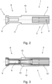
- Fig. 1 shows a perspective view of a socket contact 1 according to the invention.
- a hollow cylindrical contacting area 2 has been produced at a first end 3 of the socket contact 1 by means of extrusion.
- the hollow cylindrical contacting area 2 has contact lamellae 4 extending in the longitudinal direction L, which are separated from one another by recesses 5 in the circumferential direction of the hollow cylindrical contacting area 2.
- the front section 6 of the contact blades 4 is offset inwards parallel to the central axis A of the socket contact 1, so that a pin contact inserted into the contacting area 2 of the socket contact 1 is contacted by these front sections 6.
- the parallel offset of the sections 6 results in a linear contact area, which increases the maximum current carrying capacity of the socket contact 1, compared to conventional socket contacts with point-shaped contact areas between the contact lamellae and a pin contact.
- connection area 8 is also formed as a hollow cylindrical crimp connection at the second end 7 of the socket contact 1, the connection area 8 also being produced by extrusion.
- the connection area 8 has a funnel-shaped collar 9 at its outer end, which was created by expanding the connection area 8. Thanks to the funnel-shaped collar 9, the introduction of a conductor to be connected, in particular a stranded conductor, into the connection area 8 is made easier before the conductor is electrically connected to the socket contact 1 by crimping.
- the socket contact 1 also has a solid central region 10, which is formed between the hollow cylindrical contacting region 2 and the hollow cylindrical connection region 8.
- a stop 11 is formed on the central region 10, which can serve as a stop for fastening the socket contact 1 in a housing wall or a carrier plate.
- Fig. 3 shows a longitudinal section through the socket contact 1, similar to Fig. 2 , whereby the changed fiber layer resulting from the forming process of the socket contact 1 is also indicated here by corresponding lines 12.
- the fiber layer changed by the forming process has a positive effect on the spring properties of the contact blades 4, which leads to an increased contact force with which a pin contact inserted into the contacting area 2 is contacted.
- Fig. 4 Various steps in the production of the socket contact 1 from a solid round rod 13 are shown as the starting workpiece.
- a first stamp 14 is pressed into the round rod 13 at the second end 7, whereby the material of the round rod 13 is displaced so that it flows in the opposite direction to the direction of movement of the stamp 14.
- the outer end of the hollow cylindrical connection region 8 is expanded, whereby the funnel-shaped collar 9 is formed.
- a second stamp 15 is pressed into the round rod 2 at the first end 3 to produce the hollow cylindrical contacting area 2.
- the second stamp 15 has the negative shape of the desired contacting area 2, for which purpose corresponding webs 16 and recesses 17 formed between the webs 16 are provided on the stamp 15.
- the webs 16 create the recesses 5 in the contacting area 2, while the displaced material of the round rod 13 is opposite to the direction of movement of the Stamp 15 flows into the recesses 17, whereby the contact blades 4 of the socket contact 1 are produced.
- the front sections 6 of the contact blades 4 are displaced or pressed inwards parallel to the central axis of the socket contact 1 by compression molding. After this manufacturing step, the socket contact 1 is fully formed and can be provided with a coating if necessary.
- the front sections 6 of the contact lamellae 4 can also be displaced inwards parallel to the central axis of the socket contact 1 when the contacting area 2 is extruded. This is possible, for example, in that the contacting area 2 is produced by forward extrusion and the die into which the round rod 13 is pressed has an opening with a correspondingly smaller diameter on its output side. If the front sections 6 are pressed into this area of the opening in the die, the desired parallel offset of the front sections 6 of the contact blades 4 occurs.
Landscapes
- Engineering & Computer Science (AREA)
- Mechanical Engineering (AREA)
- Manufacturing & Machinery (AREA)
- Manufacturing Of Electrical Connectors (AREA)
Description
Die Erfindung betrifft ein Verfahren zur Herstellung eines Buchsenkontaktes aus einem Rundstab. Daneben betrifft die Erfindung noch einen nach dem Verfahren hergestellten Buchsenkontakt mit einem hohlzylindrischen Kontaktierungsbereich zum Kontaktieren eines korrespondierenden Stiftkontaktes und einem Anschlussbereich zum Anschließen eines elektrischen Leiters.The invention relates to a method for producing a socket contact from a round rod. In addition, the invention also relates to a socket contact produced by the method with a hollow cylindrical contacting area for contacting a corresponding pin contact and a connection area for connecting an electrical conductor.
Kontaktelemente zur lösbaren elektrischen Verbindung von Leitern in Form von Stift- und Buchsenkontakten sind seit vielen Jahren in unterschiedlichen Ausführungsvarianten und für verschiedene Anwendungsfälle bekannt. Die elektrische Kontaktierung zwischen dem Buchsenkontakt und dem korrespondierenden Stiftkontakt erfolgt über die am Buchsenkontakt ausgebildeten Kontaktlamellen, die den Stiftkontakt kontaktieren, wenn dieser in den Buchsenkontakt eingesteckt ist. Hierzu müssen die Kontaktlamellen eine gewisse Federkraft aufbringen, um eine sichere und dauerhafte elektrisch leitende Kontaktierung zu gewährleisten.Contact elements for the detachable electrical connection of conductors in the form of pin and socket contacts have been known for many years in different design variants and for various applications. The electrical contact between the socket contact and the corresponding pin contact takes place via the contact lamellae formed on the socket contact, which contact the pin contact when it is inserted into the socket contact. For this purpose, the contact lamellas must apply a certain spring force in order to ensure secure and permanent electrically conductive contact.
Die Herstellung der in der Praxis umfangreich eingesetzten Kontaktelemente erfolgt in der Regel durch spanende Bearbeitung eines als Ausgangsmaterial verwendeten Rundstabes, wobei die Kontaktlamellen der Buchsenkontakte durch Entfernen der Materialstege zwischen den einzelnen Kontaktlamellen mittels eines Scheibenfräsers hergestellt werden. Anschließend werden die so entstandenen Kontaktlamellen des Buchsenkontaktes etwas nach innen gedrückt, um die erforderliche Federkraft zu erzeugen. Diese Art der Herstellung eines Buchsenkontaktes ist sehr zeitaufwändig, so dass die dadurch bedingte verringerte Produktivität der Fertigungsanlagen zu einer Erhöhung der Kosten für die einzelnen Buchsenkontakte führt.The contact elements used extensively in practice are usually produced by machining a round rod used as the starting material, with the contact lamellae of the socket contacts being produced by removing the material webs between the individual contact lamellas using a disk milling cutter. The resulting contact lamellae of the socket contact are then pressed slightly inwards in order to generate the required spring force. This type of production of a socket contact is very time-consuming, so that the resulting reduced productivity of the manufacturing systems leads to an increase in the costs for the individual socket contacts.
Bei einer alternativen Herstellungsweise eines Buchsenkontaktes wird der Buchsenkontakt aus zwei Bauteilen zusammengefügt, nämlich einer einseitig geschlossenen Hülse und einem federnden Lamellenkorb, der in die Hülse eingesetzt und an dieser befestigt ist. Die elektrische und mechanische Kontaktierung eines korrespondierenden Stiftkontaktes erfolgt dabei über die Kontaktlamellen des Lamellenkorbs, der hierzu einen nach innen gebogenen Kontaktbereich aufweist.In an alternative method of manufacturing a socket contact, the socket contact is assembled from two components, namely a sleeve closed on one side and a resilient lamella basket which is inserted into the sleeve and attached to it. The electrical and mechanical contacting of a corresponding pin contact takes place via the contact lamellae of the lamella basket, which has an inwardly curved contact area for this purpose.
Ein derartiger Buchsenkontakt ist aus der
Bei diesem bekannten Buchsenkontakt ist der teilweise innerhalb der Hülse angeordnete Lamellenkorb über das vordere Ende der Hülse auf die Außenseite der Hülse umgebogen und an einem Befestigungspunkt fixiert. Eine Einstellung der Federkraft des Lamellenkorbes kann dabei bei der Herstellung des Buchsenkontaktes über die Wahl des Abstandes des Befestigungspunktes vom vorderen Ende der Hülse erfolgen. Je weiter der Befestigungspunkt vom vorderen Ende entfernt ist, desto geringer ist die Federkraft des Lamellenkorbes. Der Lamellenkorb selber wird dabei durch Ausstanzen aus einem Federblechstreifen und anschließenden Umbiegen der Kontaktlamellen hergestellt. Nachteilig ist hierbei jedoch, dass durch die Verwendung von zwei Bauteilen die Herstellung des Buchsenkontaktes aufwändig und damit teuer ist. Darüber hinaus ist der Buchsenkontakt durch die Kombination der beiden Bauteile relativ großvolumig, so dass er für kompakte Stecker ungeeignet ist.In this known socket contact, the lamella basket, which is partially arranged inside the sleeve, is bent over the front end of the sleeve onto the outside of the sleeve and fixed at an attachment point. The spring force of the lamella basket can be adjusted when producing the socket contact by selecting the distance of the fastening point from the front end of the sleeve. The further the attachment point is from the front end, the lower the spring force of the slat basket. The slat basket itself is made by punching out a spring sheet metal strip and then bending the contact slats. The disadvantage here, however, is that the use of two components means that the production of the socket contact is complex and therefore expensive. In addition, the socket contact has a relatively large volume due to the combination of the two components, making it unsuitable for compact plugs.
Aus der
Die
I Die
Die
Die
Der vorliegenden Erfindung liegt die Aufgabe zugrunde, ein Verfahren zum Herstellen eines Buchsenkontaktes aus einem Rundstab anzugeben, durch das die Fertigungszeit reduziert wird, so dass die Produktivität insbesondere bei der maschinellen Herstellung von Buchsenkontakten erhöht werden kann. Darüber hinaus soll ein Buchsenkontakt angegeben werden, der einfach und damit auch kostengünstig hergestellt werden kann.The present invention is based on the object of specifying a method for producing a socket contact from a round rod, through which the production time is reduced, so that productivity can be increased, particularly in the mechanical production of socket contacts. In addition, a socket contact should be specified that can be produced easily and therefore cost-effectively.
Diese Aufgabe ist bei dem eingangs genannten Verfahren gemäß dem Patentanspruch 1 durch folgenden Schritt gelöst:
- w Herstellen eines hohlzylindrischen Kontaktierungsbereiches an einem ersten Ende des Rundstabes mittels Fließpressen, wobei der hohlzylindrische Kontaktierungsbereich in Längsrichtung des Kontaktierungsbereiches sich erstreckende Kontaktlamellen aufweist, die in Umfangsrichtung des hohlzylindrischen Kontaktierungsbereiches durch Aussparungen voneinander getrennt sind, wobei die Aussparungen beim Fließpressen erzeugt werden,
- wozu ein Stempel, der die Negativform des gewünschten hohlzylindrischen Kontaktierungsbereiches aufweist, am ersten Ende in den Rundstab eingepresst wird, wobei das Material des Rundstabes so verdrängt wird, dass es entgegengesetzt zur Bewegungsrichtung des Stempels in die im Stempel ausgebildeten Kavitäten fließt, oder
- wozu der Rundstab mit seinem ersten Ende durch rückseitig aufgebrachten Stempeldruck in eine Matrize gepresst wird, die die Negativform des gewünschten hohlzylindrischen Kontaktierungsbereiches hat, wobei sich der Stempel und das Material des Rundstabes in die selbe Bewegungsrichtung bewegen.
- w Producing a hollow cylindrical contacting area at a first end of the round rod by means of extrusion, the hollow cylindrical contacting area having contact lamellas extending in the longitudinal direction of the contacting area, which are provided in the circumferential direction of the hollow cylindrical contacting area through recesses are separated from each other, with the recesses being created during extrusion,
- for which a stamp, which has the negative shape of the desired hollow cylindrical contacting area, is pressed into the round rod at the first end, the material of the round rod being displaced in such a way that it flows into the cavities formed in the stamp in the opposite direction to the direction of movement of the stamp, or
- for which the first end of the round rod is pressed into a die by means of stamp pressure applied to the back, which has the negative shape of the desired hollow cylindrical contacting area, with the stamp and the material of the round rod moving in the same direction of movement.
Das erfindungsgemäße Verfahren zeichnet sich zunächst dadurch aus, dass an Stelle einer spanenden Herstellung eine umformtechnische Herstellung mittels Fließpressen vorgesehen ist. Die einzelnen Kontaktlamellen werden dabei nicht durch spanende Arbeitsschritte wie Fräsen oder Sägen sondern durch Umformen beim Fließpressen hergestellt. Im Rahmen der Erfindung ist dabei festgestellt worden, dass so auf die zeitaufwändige spanende Bearbeitung verzichtet werden kann und die umformtechnische Herstellung des Kontaktierungsbereichs mit den Kontaktlamellen darüber hinaus im Vergleich zur spanenden Herstellung mehrere Vorteile aufweist.The method according to the invention is initially characterized by the fact that instead of a machining production, a forming production using extrusion is provided. The individual contact lamellas are not produced by machining steps such as milling or sawing, but rather by forming during extrusion. In the context of the invention, it has been found that time-consuming machining can be dispensed with and that the production of the contact area with the contact lamellas using forming technology also has several advantages compared to machining.
Durch den Umformprozess kann der Buchsenkontakt in seiner Mikrostruktur besser auf den späteren Lastfall vorbereitet werden. Bei der Herstellung des hohlzylindrischen Kontaktierungsbereiches mittels Fließpressen entsteht eine günstigere Faserlage im Buchsenkontakt, als dies bei einer spanenden Herstellung eines hohlzylindrischen Kontaktierungsbereiches der Fall ist. Hierdurch wird die Federeigenschaft des Kontaktierungsbereiches verbessert. Darüber hinaus werden durch das Pressen Druckeigenspannungen in das Material eingebracht, wodurch die Federwirkung der Kontaktlamellen weiter verbessert wird. Darüber hinaus wirken Druckeigenspannungen in Metallen korrosionshemmend, was bei Kontaktelementen ebenfalls vorteilhaft ist.Through the forming process, the microstructure of the socket contact can be better prepared for the later load case. When producing the hollow cylindrical contact area using extrusion, a more favorable fiber layer is created in the socket contact than is the case when a hollow cylindrical contact area is produced by machining. This improves the spring properties of the contacting area. In addition, the pressing introduces residual compressive stresses into the material, which further improves the spring effect of the contact blades. In addition, residual compressive stresses in metals have a corrosion-inhibiting effect, which is also advantageous for contact elements.
Da die Kontaktlamellen nicht durch Sägen oder Fräsen voneinander getrennt, sondern direkt beim Fließpressen hergestellt werden, kann die Fertigungszeit zur Herstellung eines Buchsenkontaktes deutlich reduziert werden. Mit einer entsprechend ausgebildeten Umformpresse kann die Produktivität, d. h. die Anzahl der innerhalb einer bestimmten Zeit hergestellten Buchsenkontakte so um ein Vielfaches erhöht werden, im Vergleich zur Herstellung von Buchsenkontakten auf einer Dreh- oder Fräsmaschine. Dadurch, dass es sich bei dem erfindungsgemäßen Herstellungsverfahren um ein spanloses Herstellungsverfahren handelt, wird darüber hinaus die Materialausnutzung erheblich gesteigert, da das Ausgangsmaterial bis zu 100 % ausgenutzt wird. Neben der geringeren Fertigungszeit wird bei dem erfindungsgemäßen Verfahren somit auch die Materialausnutzung deutlich erhöht, so dass die einzelnen Buchsenkontakte zu geringeren Kosten hergestellt werden können.Since the contact lamellae are not separated from each other by sawing or milling, but are produced directly during extrusion, the production time for producing a socket contact can be significantly reduced. With a With an appropriately designed forming press, productivity, ie the number of socket contacts produced within a certain time, can be increased many times over compared to the production of socket contacts on a lathe or milling machine. Because the manufacturing process according to the invention is a non-cutting manufacturing process, the material utilization is also significantly increased, since the starting material is utilized up to 100%. In addition to the shorter production time, the method according to the invention also significantly increases the material utilization, so that the individual socket contacts can be manufactured at lower costs.
Die Herstellung des hohlzylindrischen Kontaktierungsbereiches erfolgt dabei vorzugsweise mittels Vorwärts-Fließpressen oder Rückwärts-Fließpressen ohne vorherige Erwärmung des Rundstabes als Ausgangsmaterial. Der Vorteil des Kalt-Fließpressens liegt dabei in der hohen Maßgenauigkeit sowie der hohen Oberflächengüte des derart hergestellten Bauteils, so dass eine Nachbearbeitung der erfindungsgemäß hergestellten Buchsenkontakte in der Regel nicht erforderlich ist. Die derart hergestellten Buchsenkontakte müssen nach dem Auswerfen aus der Umformpresse allenfalls noch mit einer Beschichtung versehen werden, aber ansonsten nicht mehr weiter bearbeitet werden.The hollow cylindrical contacting area is preferably produced by means of forward extrusion or backward extrusion without prior heating of the round rod as the starting material. The advantage of cold extrusion lies in the high dimensional accuracy and the high surface quality of the component produced in this way, so that post-processing of the socket contacts produced according to the invention is generally not necessary. The socket contacts produced in this way may need to be provided with a coating after being ejected from the forming press, but otherwise no longer need to be processed.
Beim Vorwärts-Fließpressen wird der Rundstab mit seinem ersten Ende durch rückseitig aufgebrachten Stempeldruck in eine Matrize gepresst. Die Matrize, die während der Umformung feststeht, hat die Negativform des gewünschten hohlzylindrischen Kontaktierungsbereiches, wobei sich beim Vorwärts-Fließpressen der Stempel und das Material in die selbe Bewegungsrichtung bewegen. Beim Rückwärts-Fließpressen dringt ein Stempel, der die Negativform des gewünschten Kontaktierungsbereiches aufweist, am ersten Ende in den Rundstab ein. Dabei wird das Material so verdrängt, dass es entgegengesetzt zur Bewegungsrichtung des Stempels in die im Stempel ausgebildeten Kavitäten fließt.During forward extrusion, the first end of the round bar is pressed into a die by stamp pressure applied to the back. The die, which remains fixed during forming, has the negative shape of the desired hollow cylindrical contacting area, with the punch and the material moving in the same direction of movement during forward extrusion. During reverse extrusion, a punch that has the negative shape of the desired contacting area penetrates the round rod at the first end. The material is displaced in such a way that it flows into the cavities formed in the stamp in the opposite direction to the direction of movement of the stamp.
Als Material für den Rundstab wird bei dem erfindungsgemäßen Verfahren vorzugsweise Kupfer oder eine Kupferbasis-Legierung, insbesondere Umformmessing verwendet, welches im Unterschied zu Zerspannungsmessing kein Blei enthält. Blei erleichtert zwar die Zerspannung des Rundstabes, verschlechtert jedoch die Umformeigenschaften. Außerdem wird durch den Verzicht auf Blei die Leitfähigkeit des verwendeten Messings bzw. der Messinglegierung verbessert. Für das erfindungsgemäße Verfahren eignet sich dabei insbesondere Messing mit einem Zinkgehalt von maximal 36 %, vorzugsweise weniger, da dann sowohl die Leitfähigkeit als auch die Kaltformbarkeit gute Werte aufweisen.The material used for the round rod in the method according to the invention is preferably copper or a copper-based alloy, in particular formed brass, which, in contrast to machining brass, does not contain lead. Although lead makes it easier to cut the round bar, it impairs the forming properties. In addition, the waiver on lead improves the conductivity of the brass or brass alloy used. Brass with a zinc content of a maximum of 36%, preferably less, is particularly suitable for the method according to the invention, since both the conductivity and the cold formability then have good values.
Gemäß einer vorteilhaften Ausgestaltung des Verfahrens werden die Kontaktlamellen oder ein vorderer Abschnitt der Kontaktlamellen durch Umformen parallel zur Mittelachse des Buchsenkontaktes nach innen verschoben. Bei herkömmlichen Buchsenkontakten sind die Kontaktlamellen oder deren freien Enden in der Regel nach innen angestellt, so dass der Kontaktierungsbereich einen konisch zulaufenden vorderen Abschnitt aufweist. Diese Ausgestaltung des Kontaktierungsbereiches führt zu im Wesentlichen punktförmigen Kontaktbereichen, wodurch die maximale Stromtragfähigkeit begrenzt wird. Sind dagegen die Kontaktlamellen oder ein vorderer Abschnitt der Kontaktlamellen parallel nach innen versetzt, so ergeben sich linienförmige Kontaktbereiche zwischen den Kontaktlamellen des Buchsenkontaktes und einem in den Kontaktierungsbereich eingesteckten korrespondierenden Stiftkontakt, was zu einer höheren Stromtragfähigkeit führt.According to an advantageous embodiment of the method, the contact lamellae or a front section of the contact lamellae are displaced inwards parallel to the central axis of the socket contact by forming. With conventional socket contacts, the contact lamellae or their free ends are usually turned inwards, so that the contact area has a conically tapered front section. This configuration of the contacting area leads to essentially point-shaped contact areas, which limits the maximum current carrying capacity. If, on the other hand, the contact lamellae or a front section of the contact lamellae are offset parallel to the inside, linear contact areas result between the contact lamellae of the socket contact and a corresponding pin contact inserted into the contacting area, which leads to a higher current-carrying capacity.
Durch eine entsprechende Wahl der Form des Stempels bzw. der Matrize kann der Parallelversatz der Kontaktlamellen direkt bei der umformetechnischen Herstellung des Kontaktierungsbereiches durch Fließpressen erzeugt werden, so dass auf zusätzliche Herstellungsschritte, insbesondere solche, die ein Wechseln des Werkzeugs oder ein Umspannen des Werkstücks erfordern, verzichtet werden kann. Alternativ dazu kann der Parallelversatz der vorderen Abschnitte der Kontaktlamellen oder der Kontaktlamellen insgesamt auch durch Formpressen der Abschnitte bzw. der Kontaktlamellen nach der eigentlichen umformetechnischen Herstellung der Kontaktlamellen erfolgen. Auch hierbei ist ein Umspannen des Werkstücks, d. h. des Buchsenkontaktes, nicht erforderlich, so dass der zusätzliche Zeitaufwand gering ist.By appropriately choosing the shape of the punch or die, the parallel offset of the contact lamellae can be created directly during the forming process of the contacting area by extrusion, so that additional manufacturing steps, in particular those that require changing the tool or re-clamping the workpiece, can be dispensed with. Alternatively, the parallel offset of the front sections of the contact blades or the contact blades as a whole can also be carried out by compression molding of the sections or the contact blades after the actual forming process of the contact blades. Here too, the workpiece needs to be re-clamped, i.e. H. the socket contact is not required, so the additional time required is minimal.
Zum Anschließen eines elektrischen Leiters an den Buchsenkontakt weist dieser einen Anschlussbereich auf, der sich am zweiten Ende des Buchsenkontaktes, d. h. an dem dem Kontaktierungsbereich abgewandten Ende befindet. Bei dem erfindungsgemäßen Verfahren zur Herstellung eines Buchsenkontaktes wird vorzugsweise in einem ersten Verfahrensschritt ein solcher Anschlussbereich mittels Fließpressen hergestellt. Der Anschlussbereich ist dabei bevorzugt hohlzylindrisch ausgebildet, wobei es sich bei dem Anschlussbereich dann um einen Crimpanschluss handelt. Auch hierbei ist es von Vorteil, wenn das Material des Rundstabes kein Blei enthält, da durch die verbesserten Umformeigenschaften das sogenannte Crimpen eines anzuschließenden Leiters erleichtert wird.To connect an electrical conductor to the socket contact, the latter has a connection area which is located at the second end of the socket contact, ie at the end facing away from the contacting area. In the method according to the invention for producing a socket contact, such a connection area is preferably produced in a first method step by means of extrusion. The connection area is preferably hollow cylindrical, the connection area then being a crimp connection. Here too, it is advantageous if the material of the round rod does not contain lead, as the improved forming properties make the so-called crimping of a conductor to be connected easier.
Die Ausbildung eines hohlzylindrischen Anschlussbereichs im ersten Verfahrensschritt, d. h. zu Beginn des Herstellungsverfahrens des Buchsenkontaktes, hat dabei den Vorteil, dass der Anschlussbereich dann bei der Herstellung des hohlzylindrischen Kontaktierungsbereiches zur Aufnahme eines Stempels oder Gegenlagers beim Vorwärts-Fließpressen bzw. Rückwärts-Fließpressen genutzt werden kann.The formation of a hollow cylindrical connection area in the first process step, i.e. H. at the beginning of the manufacturing process of the socket contact, has the advantage that the connection area can then be used in the manufacture of the hollow cylindrical contacting area to accommodate a punch or counter bearing during forward extrusion or reverse extrusion.
Vorzugsweise wird bei einem hohlzylindrischen Anschlussbereich in einem weiteren Verfahrensschritt am äußeren Ende des Anschlussbereichs durch Aufweiten ein trichterförmiger Kragen ausgebildet. Durch die Ausbildung eines trichterförmigen Kragens wird das Einführen eines Leiters in den Anschlussbereich erleichtert. Die Ausbildung eines erweiterten, trichterförmigen Kragens ermöglicht es dabei auch, dass bei einem isolierten Leiter das Ende der Leiterisolation in den Kragen hineinragt, während der abisolierte Leiter bzw. die abisolierten Litzen im hohlzylindrischen Anschlussbereich eingesteckt sind. Dadurch kann eine Beschädigung des Leiters bzw. der Litzen am äußeren Ende des Anschlussbereichs verhindert werden.In the case of a hollow cylindrical connection area, a funnel-shaped collar is preferably formed in a further process step at the outer end of the connection area by expanding it. The formation of a funnel-shaped collar makes it easier to insert a conductor into the connection area. The formation of an extended, funnel-shaped collar also makes it possible for the end of the conductor insulation to protrude into the collar in the case of an insulated conductor, while the stripped conductor or the stripped strands are inserted into the hollow cylindrical connection area. This can prevent damage to the conductor or the strands at the outer end of the connection area.
Gemäß einer weiteren vorteilhaften Ausgestaltung wird bei dem erfindungsgemäßen Verfahren der Umformprozess dazu genutzt, die Festigkeit des Materials des Rundstabes so zu verändern, dass beim umformtechnisch hergestellten Buchsenkontakt die Festigkeit im Kontaktierungsbereich höher als im Anschlussbereich ist. Die beim Kalt-Fließpressen auftretende Verfestigung des Materials wird somit dazu genutzt, in den unterschiedlichen Bereichen des Buchsenkontakts unterschiedliche, an die jeweilige Aufgabe angepasste Festigkeiten zu erzielen. Weist der Buchsenkontakt im Anschlussbereich eine geringere Festigkeit auf, so führt dies dazu, dass die Restformbarkeit in diesem Bereich erhöht ist, was sich insbesondere bei einem als Crimpanschluss ausgebildeten Anschlussbereich als vorteilhaft erweist. Eine erhöhte Festigkeit im Kontaktierungsbereich führt zu einer verbesserten Kontaktkraft der Kontaktlamellen.According to a further advantageous embodiment, in the method according to the invention, the forming process is used to change the strength of the material of the round rod so that in the case of a socket contact produced using forming technology, the strength in the contact area is higher than in the connection area. The solidification of the material that occurs during cold extrusion is therefore used to achieve different strengths in the different areas of the socket contact, adapted to the respective task. If the socket contact has a lower strength in the connection area, this leads to the residual formability in this area being increased, which proves to be particularly advantageous in the case of a connection area designed as a crimp connection. Increased strength in the contact area leads to improved contact force of the contact lamellae.
Die zuvor genannte Aufgabe ist bei einem eingangs beschriebenen Buchsenkontakt mit einem hohlzylindrischen Kontaktierungsbereich und einem Anschlussbereich mit den Merkmalen des Patentanspruchs 6 dadurch gelöst, dass der hohlzylindrische Kontaktierungsbereich in Längsrichtung des Kontaktierungsbereiches sich erstreckende Kontaktlamellen aufweist, die in Umfangsrichtung des Kontaktierungsbereiches durch Aussparungen, die im Umformprozess erzeugt worden sind, voneinander getrennt sind, wobei die Festigkeit des Materials im Kontaktierungsbereich höher als die Festigkeit des Materials im Anschlussbereich ist. Ein derartiger Buchsenkontakt kann besonders einfach mit dem erfindungsgemäßen Verfahren hergestellt werden. Bezüglich der Vorteile des erfindungsgemäßen Buchsenkontaktes wird daher auf die zuvor beschriebenen Vorteile im Zusammenhang mit dem erfindungsgemäßen Verfahren verwiesen.The aforementioned object is achieved in the case of a socket contact described above with a hollow cylindrical contacting area and a connection area with the features of
Vorzugsweise sind bei dem erfindungsgemäßen Buchsenkontakt die Kontaktlamellen oder ein vorderer Abschnitt der Kontaktlamellen parallel zur Mittelachse des Buchsenkontakts nach innen versetzt. Ein nach innen versetzter vorderer Abschnitt der Kontaktlamellen stellt dann den Bereich der Kontaktlamellen dar, mit dem diese einen in den Kontaktierungsbereich des Buchsenkontaktes eingesteckten Stiftkontakt kontaktieren. Durch den Parallelversatz wird ein linienförmiger Kontaktbereich realisiert, so dass der Kontaktierungsbereich im Vergleich zu Kontaktlamellen mit einem punktförmigen Kontaktierungsbereich eine höhere Stromtragfähigkeit aufweist.Preferably, in the socket contact according to the invention, the contact lamellae or a front section of the contact lamellae are offset inwards parallel to the central axis of the socket contact. An inwardly offset front section of the contact blades then represents the area of the contact blades with which they contact a pin contact inserted into the contacting area of the socket contact. The parallel offset creates a linear contact area, so that the contact area has a higher current-carrying capacity compared to contact lamellas with a point-shaped contact area.
Damit der Buchsenkontakt insgesamt eine ausreichende Steifigkeit aufweist, ist zwischen dem hohlzylindrischen Kontaktierungsbereich und dem hohlzylindrischen Anschlussbereich ein massiver Mittelbereich ausgebildet. Dieser massive Mittelbereich erstreckt sich vorzugsweise über mindestens 25 % der Gesamtlänge des fertigen Buchsenkontaktes. Außerdem ist die Erstreckung des Mittelbereichs vorzugsweise etwa gleich groß wie die Erstreckung des Anschlussbereichs, während der Kontaktierungsbereich vorzugsweise eine etwas größere Erstreckung als der Mittelbereich bzw. der Anschlussbereich aufweist. Zur Positionierung des Buchsenkontaktes in einer Gehäusewand oder einer Trägerplatte kann an dem Mittelbereich darüber hinaus mindestens ein Anschlag ausgebildet sein.So that the socket contact has sufficient overall rigidity, a solid central region is formed between the hollow cylindrical contact area and the hollow cylindrical connection area. This solid central area preferably extends over at least 25% of the total length of the finished socket contact. In addition, the extent of the central region is preferably approximately the same size as the extent of the connection region, while the contacting region preferably has a slightly larger extent than the central region or the connection region. In order to position the socket contact in a housing wall or a carrier plate, at least one stop can also be formed on the central region.
Im Einzelnen gibt es mehrere Möglichkeiten, das erfindungsgemäße Verfahren und den erfindungsgemäßen Buchsenkontakt auszugestalten und weiterzubilden. Dazu wird verwiesen sowohl auf die den Patentansprüchen 1 und 7 nachgeordneten Patentansprüche, als auch auf die nachfolgende Beschreibung bevorzugter Ausführungsbeispiele in Verbindung mit der Zeichnung. In der Zeichnung zeigen
- Fig. 1
- eine perspektivische Darstellung eines erfindungsgemäßen Buchsenkontaktes,
- Fig. 2
- einen Längsschnitt durch einen erfindungsgemäßen Buchsenkontakt,
- Fig. 3
- einen Längsschnitt durch einen Buchsenkontakt gemäß
Fig. 2 , mit eingezeichneter Faserlage, und - Fig. 4
- schematisch mehrere Zwischenschritte bei der Herstellung eines erfindungsgemäßen Buchsenkontaktes.
- Fig. 1
- a perspective view of a socket contact according to the invention,
- Fig. 2
- a longitudinal section through a socket contact according to the invention,
- Fig. 3
- a longitudinal section through a socket contact
Fig. 2 , with fiber location marked, and - Fig. 4
- schematically several intermediate steps in the production of a socket contact according to the invention.
Bei dem in
Wie insbesondere aus der Schnittdarstellung des Buchsenkontaktes 1 gemäß
In
In einem nächsten Verfahrensschritt wird zur Herstellung des hohlzylindrischen Kontaktierungsbereiches 2 ein zweiter Stempel 15 am ersten Ende 3 in den Rundstab 2 eingepresst. Der zweite Stempel 15 weist dabei die Negativform des gewünschten Kontaktierungsbereiches 2 auf, wozu an dem Stempel 15 entsprechende Stege 16 und zwischen den Stegen 16 ausgebildete Ausnehmungen 17 vorgesehen sind. Durch die Stege 16 werden in dem Kontaktierungsbereich 2 die Aussparungen 5 erzeugt, während das dabei verdrängte Material des Rundstabes 13 entgegengesetzt zur Bewegungsrichtung des Stempels 15 in die Ausnehmungen 17 fließt, wodurch die Kontaktlamellen 4 des Buchsenkontakts 1 hergestellt werden.In a next process step, a
In einem weiteren Herstellungsschritt werden die vorderen Abschnitte 6 der Kontaktlamellen 4 durch Formpressen parallel zur Mittelachse des Buchsenkontakts 1 nach innen verschoben bzw. eingedrückt. Nach diesem Herstellungsschritt ist der Buchsenkontakt 1 fertig geformt und kann bei Bedarf noch mit einer Beschichtung versehen werden.In a further manufacturing step, the
Alternativ zum Parallelversatz der vorderen Abschnitte 6 der Kontaktlamellen 4 mittels Formpressen können die vorderen Abschnitte 6 der Kontaktlamellen 4 auch beim Fließpressen des Kontaktierungsbereiches 2 parallel zur Mittelachse des Buchsenkontaktes 1 nach innen verschoben werden. Dies ist beispielsweise dadurch möglich, dass der Kontaktierungsbereich 2 durch Vorwärts-Fließpresssen hergestellt wird und dabei die Matrize, in die der Rundstab 13 eingepresst wird, an ihrer Ausgangsseite eine Öffnung mit einem entsprechend geringeren Durchmesser aufweist. Wenn die vorderen Abschnitte 6 in diesen Bereich der Öffnung in der Matritze eingepresst werden, kommt es zu dem gewünschten Parallelversatz der vorderen Abschnitte 6 der Kontaktlamellen 4.As an alternative to the parallel offset of the
Claims (8)
- Method of manufacturing a socket contact (1) from a round rod (13), characterized by the following step:producing a hollow cylindrical contacting region (2) at a first end (3) of the round rod (13) by means of extrusion, wherein the hollow cylindrical contacting region (2) has contact lamellae (4) which extend in the longitudinal direction (L) of the contacting region (2) and are separated from one another in the circumferential direction of the hollow cylindrical contacting region (2) by recesses (5), wherein the recesses (5) are produced during extrusion,wherein a punch (15), which has the negative shape of the desired hollow cylindrical contacting region (2), is pressed into the round rod (13) at the first end, wherein the material of the round rod (13) is displaced in such a way that it flows into the cavities (17) designed in the punch (15) in the opposite direction to the direction of movement of the punch (15), orwhereby the round rod (13) is pressed with its first end (3) into a die having the negative shape of the desired hollow cylindrical contacting area (2) by means of punch pressure applied to the rear, wherein the punch and the material of the round rod (13) move in the same direction of movement.
- Method according to claim 1, characterized in that the contact lamellae (4) or a front section (6) of the contact lamellae (4) of the contacting region (2) are shifted inwards parallel to the central axis (A) of the socket contact (1) by reshaping.
- Method according to claim 1 or 2, characterized in that, in a further method step, a terminal region (8) for connecting an electrical conductor is produced at the second end (7) of the round rod (13) by means of extrusion.
- Method according to claim 3, characterized in that the terminal region (8) is designed as a hollow cylindrical crimp connection and, in a further method step, a funnel-shaped collar (9) is designed at its outer end by expanding.
- Method according to claim 3 or 4, characterized in that during the forming process the strength of the material of the round rod (13) is changed in such a way that the strength in the contacting region (2) is higher than in the terminal region (8).
- Socket contact (1) with a hollow cylindrical contacting region (2) for contacting a corresponding pin contact and with a terminal region (8) for connecting an electrical conductor,wherein the hollow cylindrical contacting region (2) has contact lamellae (4) extending in the longitudinal direction (L) of the contacting region (2), which are separated from each other in the circumferential direction of the hollow cylindrical contacting region (2) by recesses (5), wherein the recesses (5) were produced during the forming process,characterized inthat the socket contact (1) is produced according to the method according to any one of claims 1 to 5wherein the strength of the material in the contacting region (2) is higher than the strength of the material in the terminal region (8), andwherein the contact lamellae (4) or a front section (6) of the contact lamellae (4) are shifted inwards parallel to the center axis (A) of the socket contact (1).
- Socket contact (1) according to claim 6, characterized in that the terminal region (8) is designed as a hollow cylindrical crimp connection and a funnel-shaped collar (9) is formed at its outer end.
- Socket contact (1) according to claim 6 or 7, characterized in that a solid central region (10) is designed between the hollow cylindrical contacting region (2) and the hollow cylindrical terminal region (8), which preferably has a stop (11).
Applications Claiming Priority (2)
| Application Number | Priority Date | Filing Date | Title |
|---|---|---|---|
| DE102016123936.4A DE102016123936B4 (en) | 2016-12-09 | 2016-12-09 | Method of making a socket contact |
| PCT/EP2017/081672 WO2018104381A1 (en) | 2016-12-09 | 2017-12-06 | Method for producing a socket contact |
Publications (2)
| Publication Number | Publication Date |
|---|---|
| EP3552273A1 EP3552273A1 (en) | 2019-10-16 |
| EP3552273B1 true EP3552273B1 (en) | 2024-03-06 |
Family
ID=60574623
Family Applications (1)
| Application Number | Title | Priority Date | Filing Date |
|---|---|---|---|
| EP17808946.2A Active EP3552273B1 (en) | 2016-12-09 | 2017-12-06 | Method for producing a socket contact |
Country Status (5)
| Country | Link |
|---|---|
| EP (1) | EP3552273B1 (en) |
| CN (1) | CN110050390B (en) |
| DE (1) | DE102016123936B4 (en) |
| PL (1) | PL3552273T3 (en) |
| WO (1) | WO2018104381A1 (en) |
Families Citing this family (2)
| Publication number | Priority date | Publication date | Assignee | Title |
|---|---|---|---|---|
| DE202018104958U1 (en) * | 2018-08-30 | 2018-09-12 | Harting Electric Gmbh & Co. Kg | Connector with components of improved material |
| CN119867441B (en) * | 2024-12-27 | 2025-11-18 | 苏州海明包装科技有限公司 | A retractable brush rod automatic forming device |
Citations (12)
| Publication number | Priority date | Publication date | Assignee | Title |
|---|---|---|---|---|
| US5474479A (en) * | 1994-09-28 | 1995-12-12 | The Whitaker Corporation | Louvered contact electrical connector |
| CN1241048A (en) * | 1998-06-25 | 2000-01-12 | 三星电子国际公司 | Hoodless Electrical socket contact |
| DE10235053A1 (en) * | 2002-07-31 | 2004-02-12 | Siemens Ag | Manufacture of an electrical contact in which there is a sleeve element that is fitted onto the end of a contact bush and is laser welded |
| US20100269337A1 (en) * | 2009-04-24 | 2010-10-28 | Advanced Neuromodulation Systems, Inc. | Medical leads with segmented electrodes and methods of fabrication thereof |
| CN201975550U (en) * | 2010-12-08 | 2011-09-14 | 深圳格力浦电子有限公司 | Electric connector contact |
| EP2642604A2 (en) * | 2012-03-22 | 2013-09-25 | Harwin PLC | Electrical contact and method of manufacture |
| DE102014105534A1 (en) * | 2014-04-17 | 2015-10-22 | Phoenix Contact E-Mobility Gmbh | Socket contact and electrical plug connection |
| US20150357738A1 (en) * | 2013-01-18 | 2015-12-10 | Harting Electric Gmbh & Co., Kg | Socket contact |
| DE112014004463T5 (en) * | 2013-09-27 | 2016-06-09 | Autonetworks Technologies, Ltd. | Terminal fitting |
| EP2937943B1 (en) * | 2014-04-23 | 2017-07-26 | Japan Aviation Electronics Industry, Limited | Socket contact |
| FR3053845A1 (en) * | 2016-07-11 | 2018-01-12 | Aptiv Technologies Limited | METHODS OF MANUFACTURING AND CONNECTING A CONNECTOR |
| WO2018024462A1 (en) * | 2016-08-01 | 2018-02-08 | Phoenix Contact Gmbh & Co. Kg | Hermaphroditic electrical contact element |
Family Cites Families (12)
| Publication number | Priority date | Publication date | Assignee | Title |
|---|---|---|---|---|
| US4010539A (en) * | 1976-03-08 | 1977-03-08 | Sealectro Corporation | Method for fabricating multi-furcated electrical terminals |
| GB2152298B (en) * | 1983-12-29 | 1988-05-18 | Trw Inc | Multi-leaf electrical contact |
| JPH10302906A (en) * | 1997-04-21 | 1998-11-13 | Andrew Corp | C-shaped press fitting system with taper |
| DE10041516B4 (en) * | 2000-08-24 | 2010-09-09 | Harting Electric Gmbh & Co. Kg | Electrical connection device for high currents |
| CN100472889C (en) * | 2005-11-29 | 2009-03-25 | 郑迅江 | Plug for power converter and manufacturing method thereof |
| CN101330174A (en) * | 2008-07-15 | 2008-12-24 | 梁楚欣 | Cuprum aluminum socket connector for conductivity as well as manufacturing method and use thereof |
| US8317539B2 (en) * | 2009-08-14 | 2012-11-27 | Corning Gilbert Inc. | Coaxial interconnect and contact |
| DE102010020346A1 (en) * | 2010-05-12 | 2011-11-17 | Harting Electric Gmbh & Co. Kg | Electrical contact element |
| JP2012221774A (en) * | 2011-04-11 | 2012-11-12 | Furukawa Denko Sangyo Densen Kk | Female contact and method for manufacturing female contact |
| DE102012001560B4 (en) * | 2012-01-27 | 2013-08-29 | Schaltbau Gmbh | Plug contact socket |
| CN203932636U (en) * | 2014-07-03 | 2014-11-05 | 南帝精密股份有限公司 | Terminal manufacturing device |
| CN104979670B (en) * | 2015-07-14 | 2017-05-17 | 乐清市神创电气科技有限公司 | Cylindrical plug bush and production method |
-
2016
- 2016-12-09 DE DE102016123936.4A patent/DE102016123936B4/en active Active
-
2017
- 2017-12-06 CN CN201780075879.8A patent/CN110050390B/en active Active
- 2017-12-06 EP EP17808946.2A patent/EP3552273B1/en active Active
- 2017-12-06 WO PCT/EP2017/081672 patent/WO2018104381A1/en not_active Ceased
- 2017-12-06 PL PL17808946.2T patent/PL3552273T3/en unknown
Patent Citations (12)
| Publication number | Priority date | Publication date | Assignee | Title |
|---|---|---|---|---|
| US5474479A (en) * | 1994-09-28 | 1995-12-12 | The Whitaker Corporation | Louvered contact electrical connector |
| CN1241048A (en) * | 1998-06-25 | 2000-01-12 | 三星电子国际公司 | Hoodless Electrical socket contact |
| DE10235053A1 (en) * | 2002-07-31 | 2004-02-12 | Siemens Ag | Manufacture of an electrical contact in which there is a sleeve element that is fitted onto the end of a contact bush and is laser welded |
| US20100269337A1 (en) * | 2009-04-24 | 2010-10-28 | Advanced Neuromodulation Systems, Inc. | Medical leads with segmented electrodes and methods of fabrication thereof |
| CN201975550U (en) * | 2010-12-08 | 2011-09-14 | 深圳格力浦电子有限公司 | Electric connector contact |
| EP2642604A2 (en) * | 2012-03-22 | 2013-09-25 | Harwin PLC | Electrical contact and method of manufacture |
| US20150357738A1 (en) * | 2013-01-18 | 2015-12-10 | Harting Electric Gmbh & Co., Kg | Socket contact |
| DE112014004463T5 (en) * | 2013-09-27 | 2016-06-09 | Autonetworks Technologies, Ltd. | Terminal fitting |
| DE102014105534A1 (en) * | 2014-04-17 | 2015-10-22 | Phoenix Contact E-Mobility Gmbh | Socket contact and electrical plug connection |
| EP2937943B1 (en) * | 2014-04-23 | 2017-07-26 | Japan Aviation Electronics Industry, Limited | Socket contact |
| FR3053845A1 (en) * | 2016-07-11 | 2018-01-12 | Aptiv Technologies Limited | METHODS OF MANUFACTURING AND CONNECTING A CONNECTOR |
| WO2018024462A1 (en) * | 2016-08-01 | 2018-02-08 | Phoenix Contact Gmbh & Co. Kg | Hermaphroditic electrical contact element |
Also Published As
| Publication number | Publication date |
|---|---|
| EP3552273A1 (en) | 2019-10-16 |
| CN110050390B (en) | 2021-07-06 |
| DE102016123936B4 (en) | 2020-04-16 |
| WO2018104381A1 (en) | 2018-06-14 |
| PL3552273T3 (en) | 2024-06-24 |
| CN110050390A (en) | 2019-07-23 |
| DE102016123936A1 (en) | 2018-06-14 |
Similar Documents
| Publication | Publication Date | Title |
|---|---|---|
| EP3552277B1 (en) | Method for producing a socket contact and socket contact | |
| EP3189561B1 (en) | Crimp contact | |
| EP3298660B1 (en) | Plugging device comprising a plug pin and a contact sleeve | |
| EP3552273B1 (en) | Method for producing a socket contact | |
| DE926745C (en) | Process for making electrical contacts | |
| DE102007038219B3 (en) | Plug pin for use in e.g. plug bridge, has connection end for connection to connection wire, and middle area leading from connection end to contact end, where connection end is designed as crimped end and middle area is designed to be hollow | |
| EP2860829B1 (en) | Electrical contact element, connector and manufacturing method | |
| DE3221663A1 (en) | SPARK PLUG AND METHOD FOR THE PRODUCTION THEREOF | |
| EP1860734A1 (en) | Contact for a plug or socket | |
| EP2965385B1 (en) | Clip contact element for a printed circuit board and method for its production | |
| BE1032861B1 (en) | Electrical contact element | |
| DE1073080B (en) | Process for the production of drum current inverters for dynamoelectric machines | |
| DE10156299B4 (en) | Connecting arrangement and method for connecting a terminal element with an electrical conductor | |
| EP0721679B1 (en) | Compression-type sleeve | |
| DE102014000661B4 (en) | cable end sleeve | |
| DE102004034434B4 (en) | Method for producing a flat commutator and conductor blank for a flat commutator | |
| DE10358444A1 (en) | One-piece fuse-link, method for producing the one-piece fuse-link and device for carrying out the method | |
| DE102013201689A1 (en) | Screen housing i.e. aggregate housing, for receiving drive of motor car, has contact bush pressed into aperture of housing and coated with material that is different from material of housing | |
| DE102007062500A1 (en) | Plug pin for use in e.g. plug bridge, has connection end for connection to connection wire, and middle area leading from connection end to contact end, where connection end is designed as crimped end and middle area is designed to be hollow | |
| DE102024123549A1 (en) | Electrical contact element | |
| DE2202995B2 (en) | Collector-ring or slip-ring manufacturing method - involves using electromagnetic field to shrink ring onto cylindrical sleeve | |
| EP0524393B1 (en) | Method for the manufacture of a commutator and apparatus for implementing the method | |
| DE2038005A1 (en) | Connection for non-stripped wires, especially for communication cables | |
| DE102013210445A1 (en) | Connector element with clamping lamellae and connecting lamellae | |
| DE102012221126A1 (en) | Device for providing connection between conductor element for use with electric machine of electric and/or hybrid vehicle and sleeve, has conductor element introduced through region and extends in inserted state in region |
Legal Events
| Date | Code | Title | Description |
|---|---|---|---|
| STAA | Information on the status of an ep patent application or granted ep patent |
Free format text: STATUS: UNKNOWN |
|
| STAA | Information on the status of an ep patent application or granted ep patent |
Free format text: STATUS: THE INTERNATIONAL PUBLICATION HAS BEEN MADE |
|
| PUAI | Public reference made under article 153(3) epc to a published international application that has entered the european phase |
Free format text: ORIGINAL CODE: 0009012 |
|
| STAA | Information on the status of an ep patent application or granted ep patent |
Free format text: STATUS: REQUEST FOR EXAMINATION WAS MADE |
|
| 17P | Request for examination filed |
Effective date: 20190709 |
|
| AK | Designated contracting states |
Kind code of ref document: A1 Designated state(s): AL AT BE BG CH CY CZ DE DK EE ES FI FR GB GR HR HU IE IS IT LI LT LU LV MC MK MT NL NO PL PT RO RS SE SI SK SM TR |
|
| AX | Request for extension of the european patent |
Extension state: BA ME |
|
| DAV | Request for validation of the european patent (deleted) | ||
| DAX | Request for extension of the european patent (deleted) | ||
| STAA | Information on the status of an ep patent application or granted ep patent |
Free format text: STATUS: EXAMINATION IS IN PROGRESS |
|
| 17Q | First examination report despatched |
Effective date: 20201216 |
|
| P01 | Opt-out of the competence of the unified patent court (upc) registered |
Effective date: 20230512 |
|
| REG | Reference to a national code |
Ref country code: DE Ref legal event code: R079 Free format text: PREVIOUS MAIN CLASS: H01R0013110000 Ipc: B21C0023180000 Ref document number: 502017015911 Country of ref document: DE |
|
| RIC1 | Information provided on ipc code assigned before grant |
Ipc: B21K 23/00 20060101ALI20230816BHEP Ipc: H01R 43/16 20060101ALI20230816BHEP Ipc: H01R 13/11 20060101ALI20230816BHEP Ipc: B21C 23/18 20060101AFI20230816BHEP |
|
| GRAP | Despatch of communication of intention to grant a patent |
Free format text: ORIGINAL CODE: EPIDOSNIGR1 |
|
| STAA | Information on the status of an ep patent application or granted ep patent |
Free format text: STATUS: GRANT OF PATENT IS INTENDED |
|
| INTG | Intention to grant announced |
Effective date: 20230929 |
|
| GRAS | Grant fee paid |
Free format text: ORIGINAL CODE: EPIDOSNIGR3 |
|
| GRAA | (expected) grant |
Free format text: ORIGINAL CODE: 0009210 |
|
| STAA | Information on the status of an ep patent application or granted ep patent |
Free format text: STATUS: THE PATENT HAS BEEN GRANTED |
|
| AK | Designated contracting states |
Kind code of ref document: B1 Designated state(s): AL AT BE BG CH CY CZ DE DK EE ES FI FR GB GR HR HU IE IS IT LI LT LU LV MC MK MT NL NO PL PT RO RS SE SI SK SM TR |
|
| REG | Reference to a national code |
Ref country code: GB Ref legal event code: FG4D Free format text: NOT ENGLISH |
|
| REG | Reference to a national code |
Ref country code: CH Ref legal event code: EP |
|
| REG | Reference to a national code |
Ref country code: IE Ref legal event code: FG4D Free format text: LANGUAGE OF EP DOCUMENT: GERMAN |
|
| REG | Reference to a national code |
Ref country code: DE Ref legal event code: R096 Ref document number: 502017015911 Country of ref document: DE |
|
| REG | Reference to a national code |
Ref country code: LT Ref legal event code: MG9D |
|
| PG25 | Lapsed in a contracting state [announced via postgrant information from national office to epo] |
Ref country code: LT Free format text: LAPSE BECAUSE OF FAILURE TO SUBMIT A TRANSLATION OF THE DESCRIPTION OR TO PAY THE FEE WITHIN THE PRESCRIBED TIME-LIMIT Effective date: 20240306 |
|
| REG | Reference to a national code |
Ref country code: NL Ref legal event code: MP Effective date: 20240306 |
|
| PG25 | Lapsed in a contracting state [announced via postgrant information from national office to epo] |
Ref country code: GR Free format text: LAPSE BECAUSE OF FAILURE TO SUBMIT A TRANSLATION OF THE DESCRIPTION OR TO PAY THE FEE WITHIN THE PRESCRIBED TIME-LIMIT Effective date: 20240607 |
|
| PG25 | Lapsed in a contracting state [announced via postgrant information from national office to epo] |
Ref country code: HR Free format text: LAPSE BECAUSE OF FAILURE TO SUBMIT A TRANSLATION OF THE DESCRIPTION OR TO PAY THE FEE WITHIN THE PRESCRIBED TIME-LIMIT Effective date: 20240306 Ref country code: RS Free format text: LAPSE BECAUSE OF FAILURE TO SUBMIT A TRANSLATION OF THE DESCRIPTION OR TO PAY THE FEE WITHIN THE PRESCRIBED TIME-LIMIT Effective date: 20240606 |
|
| PG25 | Lapsed in a contracting state [announced via postgrant information from national office to epo] |
Ref country code: ES Free format text: LAPSE BECAUSE OF FAILURE TO SUBMIT A TRANSLATION OF THE DESCRIPTION OR TO PAY THE FEE WITHIN THE PRESCRIBED TIME-LIMIT Effective date: 20240306 |
|
| PG25 | Lapsed in a contracting state [announced via postgrant information from national office to epo] |
Ref country code: RS Free format text: LAPSE BECAUSE OF FAILURE TO SUBMIT A TRANSLATION OF THE DESCRIPTION OR TO PAY THE FEE WITHIN THE PRESCRIBED TIME-LIMIT Effective date: 20240606 Ref country code: NO Free format text: LAPSE BECAUSE OF FAILURE TO SUBMIT A TRANSLATION OF THE DESCRIPTION OR TO PAY THE FEE WITHIN THE PRESCRIBED TIME-LIMIT Effective date: 20240606 Ref country code: LT Free format text: LAPSE BECAUSE OF FAILURE TO SUBMIT A TRANSLATION OF THE DESCRIPTION OR TO PAY THE FEE WITHIN THE PRESCRIBED TIME-LIMIT Effective date: 20240306 Ref country code: HR Free format text: LAPSE BECAUSE OF FAILURE TO SUBMIT A TRANSLATION OF THE DESCRIPTION OR TO PAY THE FEE WITHIN THE PRESCRIBED TIME-LIMIT Effective date: 20240306 Ref country code: GR Free format text: LAPSE BECAUSE OF FAILURE TO SUBMIT A TRANSLATION OF THE DESCRIPTION OR TO PAY THE FEE WITHIN THE PRESCRIBED TIME-LIMIT Effective date: 20240607 Ref country code: FI Free format text: LAPSE BECAUSE OF FAILURE TO SUBMIT A TRANSLATION OF THE DESCRIPTION OR TO PAY THE FEE WITHIN THE PRESCRIBED TIME-LIMIT Effective date: 20240306 Ref country code: ES Free format text: LAPSE BECAUSE OF FAILURE TO SUBMIT A TRANSLATION OF THE DESCRIPTION OR TO PAY THE FEE WITHIN THE PRESCRIBED TIME-LIMIT Effective date: 20240306 Ref country code: BG Free format text: LAPSE BECAUSE OF FAILURE TO SUBMIT A TRANSLATION OF THE DESCRIPTION OR TO PAY THE FEE WITHIN THE PRESCRIBED TIME-LIMIT Effective date: 20240306 |
|
| PG25 | Lapsed in a contracting state [announced via postgrant information from national office to epo] |
Ref country code: SE Free format text: LAPSE BECAUSE OF FAILURE TO SUBMIT A TRANSLATION OF THE DESCRIPTION OR TO PAY THE FEE WITHIN THE PRESCRIBED TIME-LIMIT Effective date: 20240306 Ref country code: LV Free format text: LAPSE BECAUSE OF FAILURE TO SUBMIT A TRANSLATION OF THE DESCRIPTION OR TO PAY THE FEE WITHIN THE PRESCRIBED TIME-LIMIT Effective date: 20240306 |
|
| PG25 | Lapsed in a contracting state [announced via postgrant information from national office to epo] |
Ref country code: NL Free format text: LAPSE BECAUSE OF FAILURE TO SUBMIT A TRANSLATION OF THE DESCRIPTION OR TO PAY THE FEE WITHIN THE PRESCRIBED TIME-LIMIT Effective date: 20240306 |
|
| PG25 | Lapsed in a contracting state [announced via postgrant information from national office to epo] |
Ref country code: NL Free format text: LAPSE BECAUSE OF FAILURE TO SUBMIT A TRANSLATION OF THE DESCRIPTION OR TO PAY THE FEE WITHIN THE PRESCRIBED TIME-LIMIT Effective date: 20240306 |
|
| PG25 | Lapsed in a contracting state [announced via postgrant information from national office to epo] |
Ref country code: IS Free format text: LAPSE BECAUSE OF FAILURE TO SUBMIT A TRANSLATION OF THE DESCRIPTION OR TO PAY THE FEE WITHIN THE PRESCRIBED TIME-LIMIT Effective date: 20240706 |
|
| PG25 | Lapsed in a contracting state [announced via postgrant information from national office to epo] |
Ref country code: PT Free format text: LAPSE BECAUSE OF FAILURE TO SUBMIT A TRANSLATION OF THE DESCRIPTION OR TO PAY THE FEE WITHIN THE PRESCRIBED TIME-LIMIT Effective date: 20240708 Ref country code: SM Free format text: LAPSE BECAUSE OF FAILURE TO SUBMIT A TRANSLATION OF THE DESCRIPTION OR TO PAY THE FEE WITHIN THE PRESCRIBED TIME-LIMIT Effective date: 20240306 |
|
| PG25 | Lapsed in a contracting state [announced via postgrant information from national office to epo] |
Ref country code: CZ Free format text: LAPSE BECAUSE OF FAILURE TO SUBMIT A TRANSLATION OF THE DESCRIPTION OR TO PAY THE FEE WITHIN THE PRESCRIBED TIME-LIMIT Effective date: 20240306 Ref country code: EE Free format text: LAPSE BECAUSE OF FAILURE TO SUBMIT A TRANSLATION OF THE DESCRIPTION OR TO PAY THE FEE WITHIN THE PRESCRIBED TIME-LIMIT Effective date: 20240306 |
|
| PG25 | Lapsed in a contracting state [announced via postgrant information from national office to epo] |
Ref country code: SK Free format text: LAPSE BECAUSE OF FAILURE TO SUBMIT A TRANSLATION OF THE DESCRIPTION OR TO PAY THE FEE WITHIN THE PRESCRIBED TIME-LIMIT Effective date: 20240306 |
|
| PG25 | Lapsed in a contracting state [announced via postgrant information from national office to epo] |
Ref country code: SM Free format text: LAPSE BECAUSE OF FAILURE TO SUBMIT A TRANSLATION OF THE DESCRIPTION OR TO PAY THE FEE WITHIN THE PRESCRIBED TIME-LIMIT Effective date: 20240306 Ref country code: SK Free format text: LAPSE BECAUSE OF FAILURE TO SUBMIT A TRANSLATION OF THE DESCRIPTION OR TO PAY THE FEE WITHIN THE PRESCRIBED TIME-LIMIT Effective date: 20240306 Ref country code: RO Free format text: LAPSE BECAUSE OF FAILURE TO SUBMIT A TRANSLATION OF THE DESCRIPTION OR TO PAY THE FEE WITHIN THE PRESCRIBED TIME-LIMIT Effective date: 20240306 Ref country code: PT Free format text: LAPSE BECAUSE OF FAILURE TO SUBMIT A TRANSLATION OF THE DESCRIPTION OR TO PAY THE FEE WITHIN THE PRESCRIBED TIME-LIMIT Effective date: 20240708 Ref country code: IS Free format text: LAPSE BECAUSE OF FAILURE TO SUBMIT A TRANSLATION OF THE DESCRIPTION OR TO PAY THE FEE WITHIN THE PRESCRIBED TIME-LIMIT Effective date: 20240706 Ref country code: EE Free format text: LAPSE BECAUSE OF FAILURE TO SUBMIT A TRANSLATION OF THE DESCRIPTION OR TO PAY THE FEE WITHIN THE PRESCRIBED TIME-LIMIT Effective date: 20240306 Ref country code: CZ Free format text: LAPSE BECAUSE OF FAILURE TO SUBMIT A TRANSLATION OF THE DESCRIPTION OR TO PAY THE FEE WITHIN THE PRESCRIBED TIME-LIMIT Effective date: 20240306 |
|
| REG | Reference to a national code |
Ref country code: DE Ref legal event code: R097 Ref document number: 502017015911 Country of ref document: DE |
|
| PLBE | No opposition filed within time limit |
Free format text: ORIGINAL CODE: 0009261 |
|
| STAA | Information on the status of an ep patent application or granted ep patent |
Free format text: STATUS: NO OPPOSITION FILED WITHIN TIME LIMIT |
|
| PG25 | Lapsed in a contracting state [announced via postgrant information from national office to epo] |
Ref country code: DK Free format text: LAPSE BECAUSE OF FAILURE TO SUBMIT A TRANSLATION OF THE DESCRIPTION OR TO PAY THE FEE WITHIN THE PRESCRIBED TIME-LIMIT Effective date: 20240306 |
|
| PG25 | Lapsed in a contracting state [announced via postgrant information from national office to epo] |
Ref country code: DK Free format text: LAPSE BECAUSE OF FAILURE TO SUBMIT A TRANSLATION OF THE DESCRIPTION OR TO PAY THE FEE WITHIN THE PRESCRIBED TIME-LIMIT Effective date: 20240306 |
|
| 26N | No opposition filed |
Effective date: 20241209 |
|
| PG25 | Lapsed in a contracting state [announced via postgrant information from national office to epo] |
Ref country code: SI Free format text: LAPSE BECAUSE OF FAILURE TO SUBMIT A TRANSLATION OF THE DESCRIPTION OR TO PAY THE FEE WITHIN THE PRESCRIBED TIME-LIMIT Effective date: 20240306 |
|
| PGFP | Annual fee paid to national office [announced via postgrant information from national office to epo] |
Ref country code: CH Payment date: 20250101 Year of fee payment: 8 |
|
| REG | Reference to a national code |
Ref country code: DE Ref legal event code: R119 Ref document number: 502017015911 Country of ref document: DE |
|
| PG25 | Lapsed in a contracting state [announced via postgrant information from national office to epo] |
Ref country code: MC Free format text: LAPSE BECAUSE OF FAILURE TO SUBMIT A TRANSLATION OF THE DESCRIPTION OR TO PAY THE FEE WITHIN THE PRESCRIBED TIME-LIMIT Effective date: 20240306 |
|
| PG25 | Lapsed in a contracting state [announced via postgrant information from national office to epo] |
Ref country code: LU Free format text: LAPSE BECAUSE OF NON-PAYMENT OF DUE FEES Effective date: 20241206 |
|
| GBPC | Gb: european patent ceased through non-payment of renewal fee |
Effective date: 20241206 |
|
| REG | Reference to a national code |
Ref country code: BE Ref legal event code: MM Effective date: 20241231 |
|
| PG25 | Lapsed in a contracting state [announced via postgrant information from national office to epo] |
Ref country code: DE Free format text: LAPSE BECAUSE OF NON-PAYMENT OF DUE FEES Effective date: 20250701 |
|
| PG25 | Lapsed in a contracting state [announced via postgrant information from national office to epo] |
Ref country code: BE Free format text: LAPSE BECAUSE OF NON-PAYMENT OF DUE FEES Effective date: 20241231 Ref country code: GB Free format text: LAPSE BECAUSE OF NON-PAYMENT OF DUE FEES Effective date: 20241206 |
|
| PG25 | Lapsed in a contracting state [announced via postgrant information from national office to epo] |
Ref country code: IE Free format text: LAPSE BECAUSE OF NON-PAYMENT OF DUE FEES Effective date: 20241206 |
|
| REG | Reference to a national code |
Ref country code: CH Ref legal event code: U11 Free format text: ST27 STATUS EVENT CODE: U-0-0-U10-U11 (AS PROVIDED BY THE NATIONAL OFFICE) Effective date: 20260101 |
|
| PGFP | Annual fee paid to national office [announced via postgrant information from national office to epo] |
Ref country code: AT Payment date: 20251218 Year of fee payment: 9 |
|
| PGFP | Annual fee paid to national office [announced via postgrant information from national office to epo] |
Ref country code: IT Payment date: 20251218 Year of fee payment: 9 |
|
| PGFP | Annual fee paid to national office [announced via postgrant information from national office to epo] |
Ref country code: FR Payment date: 20251230 Year of fee payment: 9 |
|
| PGFP | Annual fee paid to national office [announced via postgrant information from national office to epo] |
Ref country code: PL Payment date: 20251127 Year of fee payment: 9 |