EP3552264B1 - Verfahren zur herstellung einer membran-elektroden-einheit für eine brennstoffzelle - Google Patents
Verfahren zur herstellung einer membran-elektroden-einheit für eine brennstoffzelle Download PDFInfo
- Publication number
- EP3552264B1 EP3552264B1 EP17821694.1A EP17821694A EP3552264B1 EP 3552264 B1 EP3552264 B1 EP 3552264B1 EP 17821694 A EP17821694 A EP 17821694A EP 3552264 B1 EP3552264 B1 EP 3552264B1
- Authority
- EP
- European Patent Office
- Prior art keywords
- membrane
- cutting
- deposition
- fuel cell
- electrode assembly
- Prior art date
- Legal status (The legal status is an assumption and is not a legal conclusion. Google has not performed a legal analysis and makes no representation as to the accuracy of the status listed.)
- Active
Links
Images

Classifications
-
- H—ELECTRICITY
- H01—ELECTRIC ELEMENTS
- H01M—PROCESSES OR MEANS, e.g. BATTERIES, FOR THE DIRECT CONVERSION OF CHEMICAL ENERGY INTO ELECTRICAL ENERGY
- H01M8/00—Fuel cells; Manufacture thereof
- H01M8/10—Fuel cells with solid electrolytes
- H01M8/1004—Fuel cells with solid electrolytes characterised by membrane-electrode assemblies [MEA]
-
- H—ELECTRICITY
- H01—ELECTRIC ELEMENTS
- H01M—PROCESSES OR MEANS, e.g. BATTERIES, FOR THE DIRECT CONVERSION OF CHEMICAL ENERGY INTO ELECTRICAL ENERGY
- H01M4/00—Electrodes
- H01M4/86—Inert electrodes with catalytic activity, e.g. for fuel cells
- H01M4/88—Processes of manufacture
- H01M4/8803—Supports for the deposition of the catalytic active composition
- H01M4/881—Electrolytic membranes
-
- H—ELECTRICITY
- H01—ELECTRIC ELEMENTS
- H01M—PROCESSES OR MEANS, e.g. BATTERIES, FOR THE DIRECT CONVERSION OF CHEMICAL ENERGY INTO ELECTRICAL ENERGY
- H01M4/00—Electrodes
- H01M4/86—Inert electrodes with catalytic activity, e.g. for fuel cells
- H01M4/88—Processes of manufacture
- H01M4/8825—Methods for deposition of the catalytic active composition
- H01M4/8828—Coating with slurry or ink
- H01M4/8835—Screen printing
-
- H—ELECTRICITY
- H01—ELECTRIC ELEMENTS
- H01M—PROCESSES OR MEANS, e.g. BATTERIES, FOR THE DIRECT CONVERSION OF CHEMICAL ENERGY INTO ELECTRICAL ENERGY
- H01M4/00—Electrodes
- H01M4/86—Inert electrodes with catalytic activity, e.g. for fuel cells
- H01M4/90—Selection of catalytic material
- H01M4/92—Metals of platinum group
-
- H—ELECTRICITY
- H01—ELECTRIC ELEMENTS
- H01M—PROCESSES OR MEANS, e.g. BATTERIES, FOR THE DIRECT CONVERSION OF CHEMICAL ENERGY INTO ELECTRICAL ENERGY
- H01M8/00—Fuel cells; Manufacture thereof
- H01M8/02—Details
- H01M8/0271—Sealing or supporting means around electrodes, matrices or membranes
- H01M8/0273—Sealing or supporting means around electrodes, matrices or membranes with sealing or supporting means in the form of a frame
-
- H—ELECTRICITY
- H01—ELECTRIC ELEMENTS
- H01M—PROCESSES OR MEANS, e.g. BATTERIES, FOR THE DIRECT CONVERSION OF CHEMICAL ENERGY INTO ELECTRICAL ENERGY
- H01M8/00—Fuel cells; Manufacture thereof
- H01M8/02—Details
- H01M8/0271—Sealing or supporting means around electrodes, matrices or membranes
- H01M8/0286—Processes for forming seals
-
- H—ELECTRICITY
- H01—ELECTRIC ELEMENTS
- H01M—PROCESSES OR MEANS, e.g. BATTERIES, FOR THE DIRECT CONVERSION OF CHEMICAL ENERGY INTO ELECTRICAL ENERGY
- H01M8/00—Fuel cells; Manufacture thereof
- H01M8/24—Grouping of fuel cells, e.g. stacking of fuel cells
- H01M8/241—Grouping of fuel cells, e.g. stacking of fuel cells with solid or matrix-supported electrolytes
- H01M8/242—Grouping of fuel cells, e.g. stacking of fuel cells with solid or matrix-supported electrolytes comprising framed electrodes or intermediary frame-like gaskets
-
- H—ELECTRICITY
- H01—ELECTRIC ELEMENTS
- H01M—PROCESSES OR MEANS, e.g. BATTERIES, FOR THE DIRECT CONVERSION OF CHEMICAL ENERGY INTO ELECTRICAL ENERGY
- H01M8/00—Fuel cells; Manufacture thereof
- H01M8/10—Fuel cells with solid electrolytes
- H01M2008/1095—Fuel cells with polymeric electrolytes
-
- H—ELECTRICITY
- H01—ELECTRIC ELEMENTS
- H01M—PROCESSES OR MEANS, e.g. BATTERIES, FOR THE DIRECT CONVERSION OF CHEMICAL ENERGY INTO ELECTRICAL ENERGY
- H01M4/00—Electrodes
- H01M4/86—Inert electrodes with catalytic activity, e.g. for fuel cells
- H01M4/90—Selection of catalytic material
- H01M4/9041—Metals or alloys
- H01M4/905—Metals or alloys specially used in fuel cell operating at high temperature, e.g. SOFC
- H01M4/9058—Metals or alloys specially used in fuel cell operating at high temperature, e.g. SOFC of noble metals or noble-metal based alloys
-
- H—ELECTRICITY
- H01—ELECTRIC ELEMENTS
- H01M—PROCESSES OR MEANS, e.g. BATTERIES, FOR THE DIRECT CONVERSION OF CHEMICAL ENERGY INTO ELECTRICAL ENERGY
- H01M8/00—Fuel cells; Manufacture thereof
- H01M8/24—Grouping of fuel cells, e.g. stacking of fuel cells
- H01M8/241—Grouping of fuel cells, e.g. stacking of fuel cells with solid or matrix-supported electrolytes
-
- Y—GENERAL TAGGING OF NEW TECHNOLOGICAL DEVELOPMENTS; GENERAL TAGGING OF CROSS-SECTIONAL TECHNOLOGIES SPANNING OVER SEVERAL SECTIONS OF THE IPC; TECHNICAL SUBJECTS COVERED BY FORMER USPC CROSS-REFERENCE ART COLLECTIONS [XRACs] AND DIGESTS
- Y02—TECHNOLOGIES OR APPLICATIONS FOR MITIGATION OR ADAPTATION AGAINST CLIMATE CHANGE
- Y02E—REDUCTION OF GREENHOUSE GAS [GHG] EMISSIONS, RELATED TO ENERGY GENERATION, TRANSMISSION OR DISTRIBUTION
- Y02E60/00—Enabling technologies; Technologies with a potential or indirect contribution to GHG emissions mitigation
- Y02E60/30—Hydrogen technology
- Y02E60/50—Fuel cells
-
- Y—GENERAL TAGGING OF NEW TECHNOLOGICAL DEVELOPMENTS; GENERAL TAGGING OF CROSS-SECTIONAL TECHNOLOGIES SPANNING OVER SEVERAL SECTIONS OF THE IPC; TECHNICAL SUBJECTS COVERED BY FORMER USPC CROSS-REFERENCE ART COLLECTIONS [XRACs] AND DIGESTS
- Y02—TECHNOLOGIES OR APPLICATIONS FOR MITIGATION OR ADAPTATION AGAINST CLIMATE CHANGE
- Y02P—CLIMATE CHANGE MITIGATION TECHNOLOGIES IN THE PRODUCTION OR PROCESSING OF GOODS
- Y02P70/00—Climate change mitigation technologies in the production process for final industrial or consumer products
- Y02P70/50—Manufacturing or production processes characterised by the final manufactured product
Definitions
- the present invention relates to the field of fuel cells, and more particularly to the field of the manufacture and assembly of fuel cells.
- a fuel cell allows the generation of electrical energy by an electrochemical reaction from a fuel, generally hydrogen, and an oxidizer, generally oxygen.
- a fuel cell of the solid electrolyte proton exchange membrane (PEMFC) type usually comprises a stack of elementary cells, in the form of plates, constituting electrochemical generators, each of the cells being separated from the adjacent cells by bipolar plates.
- Each cell comprises an anode element and a cathode element, separated by a solid electrolyte in the form of an ion exchange membrane, made for example of a sulfurized perfluorinated polymer material.
- each bipolar plate provides on one side the supply of fuel to the cell adjacent to this side and on the other side the supply of oxidizer to the cell adjacent to this other side, the supplies provided. by the bipolar plates being done in parallel.
- Gas diffusion layers for example made of carbon fabric, are installed on either side of the MEAs to ensure electrical conduction and the homogeneous arrival of the reactive gases supplied via the bipolar plates.
- a catalyst usually platinum, is used in the stack. This catalyst can be positioned either on the membrane or on the gas diffusion layer.
- the present invention thus aims to provide a process for depositing catalysis on a polymer membrane for a fuel cell which makes it possible to remedy the aforementioned drawbacks.
- catalyst chemical element may be replaced by the term “catalysis” for the sake of simplification of the description.
- This chemical catalyst element is preferably an ink comprising platinum, water and solvents.
- This invention thus makes it possible to overcome the aforementioned drawbacks by proposing a method in which the membrane is maintained during the two stages of catalysis deposition, which prevents it from shrinking.
- the membrane is held by a support film, for example made of a plastic material such as PET.
- a support film is conventionally used for transporting membranes in the form of a roll.
- the membrane When the catalysis is deposited on the second face, the membrane is held on its periphery by the reinforcing elements which will have been installed beforehand.
- the reinforcing elements are polymer films which are positioned so as to take sandwiching the edge of the membrane over its entire periphery, leaving a central part of the membrane free.
- the catalysis must then be deposited not on the reinforcing elements, but only on the central part of the membrane left free.
- the fourth step is advantageously implemented by a method making it possible to produce a pattern rather than a continuous deposit.
- this fourth step is advantageously carried out by a process included in the group comprising: flexography, screen printing, spraying.
- the deposition of the catalysis on the first face of the membrane can, for its part, be carried out continuously over the entire surface of the membrane, for example using a coating-type process.
- the amount of catalysis deposited is not determined by measuring a deposited thickness, but by measuring a deposited mass.
- the mass of catalysis deposited is of the order of a milligram.
- the catalysis is generally deposited in the form of a still containing solvents. Before handling the catalyzed membrane, it is useful to wait until the evaporation of the solvents is complete.
- the second step is carried out after a predetermined time at the end of the first step.
- the waiting time is generally between ten seconds and one minute for a membrane a few microns thick, or a few tens of microns.
- the seals are installed beforehand on the reinforcing elements, before the membrane is inserted.
- Such an embodiment has two advantages: firstly, since the seals are installed before the membrane is inserted, the oven polymerization steps of the seal are not undergone by the membrane; furthermore, in the event of a defect during the manufacture of the seal, only a reinforcement is lost, and not the membrane.
- the presence of an extra thickness due to the joints could be a drawback.
- the figure 1 shows a membrane-electrode assembly for a fuel cell.
- This assembly comprises an ion exchange membrane 1, reinforcing elements 2 and 2 ', gaskets 3 and 3', and gas diffusion layers 4 and 4 '.
- the present invention relates to the first possibility, namely the deposition of the catalysis on the membrane 1.
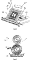
- the figure 2 shows a system allowing the implementation of a coating process.
- This system comprises a support roll 10 on which circulates a membrane 11 intended to receive catalysis.
- the system also comprises an application roller 12 which, on one side, soaks in a tank, not shown, containing the catalysis, and on the other side comes into contact with the membrane 11 installed on the support roller 10.
- the system further comprises an adjustment roller 13 installed between the dipping tank and the point of contact between the rollers 10 and 12.
- the distance between the adjustment roller and the application roller 12 can be adjusted according to the amount of catalysis that is to be deposited.
- the figure 3 shows a system allowing the implementation of a screen printing process.
- This system comprises a screen or frame 20, formed of a PET fabric 21, also called a mesh, whose meshes and wire diameter can be adapted to different uses.
- the fabric is coated with a photosensitive product called an emulsion on which is deposited a stencil corresponding to the pattern to be produced.
- the pattern to be produced corresponds to the central part of an ion exchange membrane, left free after installation of the reinforcements.
- the photosensitive product After being exposed to a UV lamp, the photosensitive product hardens except for the area masked by the template. The surplus is then cleaned up. Thus, the mesh then comprises open meshes 22, forming the pattern, and closed meshes 23.
- the doctor blade 27 will then force the mesh 21 to deform, bringing it into contact with the support 32.
- the catalysis is then forced when the doctor blade passes through the mesh to come and be deposited on the membrane 24.
- doctor blade also makes it possible to scrape the excess catalysis from the surface of the screen, the latter therefore being ready for a second removal.
- the figure 4 illustrates another process for performing this deposition in the form of a pattern, namely a flexography process, also called “ink pad”.
- the system shown in figure 4 comprises a support roll 30, on which is installed the membrane 31 to be catalyzed.
- the system also comprises an ink roller 32 on which the pattern to be deposited is formed in excess thickness.
- the system further comprises a roller 33 intended to remove, after soaking in a tank 34 comprising the chemical catalyst element, the ink present on the parts of the inking roller not forming the pattern.
- the pattern drawn on the ink roller 32 is transferred to the membrane 31.
- the gaskets are flat gaskets deposited on the reinforcement-catalyzed membrane - reinforcement assembly.
Landscapes
- Chemical & Material Sciences (AREA)
- Engineering & Computer Science (AREA)
- Chemical Kinetics & Catalysis (AREA)
- Electrochemistry (AREA)
- General Chemical & Material Sciences (AREA)
- Manufacturing & Machinery (AREA)
- Life Sciences & Earth Sciences (AREA)
- Sustainable Development (AREA)
- Sustainable Energy (AREA)
- Materials Engineering (AREA)
- Fuel Cell (AREA)
- Inert Electrodes (AREA)
Claims (8)
- Verfahren zur Fertigung einer Membran-Elektroden-Anordnung für eine Brennstoffzelle, das Verfahren umfassend die folgenden Schritte:- Einen ersten Schritt, bei dem ein chemisches Katalysatorelement auf eine erste Seite einer Ionenaustauschmembran (1) aufgebracht wird, wobei die Membran auf einem Trägerfilm gehalten wird,- Einen zweiten Schritt, bei dem die Membran vom Trägerfilm entfernt wird,- Einen dritten Schritt, bei dem die Membran zwischen zwei Verstärkungselemente (2, 2') eingefügt wird, und- Einen vierten Schritt, bei dem ein chemisches Katalysatorelement auf dem freigelassenen Abschnitt der zweiten Seite der Membran aufgebracht wird, wobei die Membran an ihrem Umfang von den Verstärkungselementen (2, 2') gehalten wird.
- Aufbringungsverfahren nach Anspruch 1, wobei das chemische Katalysatorelement eine Tinte ist, die Platin, Wasser und Lösungsmittel umfasst.
- Aufbringungsverfahren nach Anspruch 1 oder 2, wobei der Trägerfilm ein Film aus Kunststoff, zum Beispiel PET ist.
- Aufbringungsverfahren nach einem der vorhergehenden Ansprüche, wobei die Aufbringung auf die erste Seite eine Aufbringung ist, die durchgehend über die gesamte Oberfläche der Membran durchgeführt wird.
- Aufbringungsverfahren nach einem der vorhergehenden Ansprüche, wobei der zweite Schritt nach einer vorbestimmten Zeit nach dem ersten Schritt startet.
- Aufbringungsverfahren nach einem der vorhergehenden Ansprüche, wobei der vierte Schritt durch ein Verfahren durchgeführt wird, das in der Gruppe enthalten ist, die Folgendes umfasst: Flexodruck, Siebdruck und Sprühen.
- Verfahren nach einem der vorhergehenden Ansprüche, wobei die Dichtungen (3, 3') auf den Verstärkungen vorhanden sind.
- Verfahren zur Fertigung einer Elementarzelle für eine Brennstoffzelle, die zwei identische Bipolarplatten umfasst, die eine Membran-Elektroden-Anordnung und zwei Gasdiffusionsschichten umgeben, das Verfahren umfassend die folgenden Schritte:- Auf einem Stanzamboss wird eine Folie aus einem Material abgelegt, das zur Bildung von Dichtungen für eine Brennstoffzelle genutzt wird,- Es werden zwei Klemmen zur Positionierung der Folie auf der Stanzpresse angebracht,- Es wird eine erste Stanzung mit einem Werkzeug durchgeführt, dessen Größe von der Form der Bipolarplatten der Elementarzelle abhängig ist, wobei diese erste Stanzung zum Ziel hat, die Innenform der Dichtung zu begrenzen,- Es werden die Abfälle der ersten Stanzung beseitigt, wobei die Dichtung mithilfe der Klemmen an ihrem Platz gehalten wird,- Es wird eine Membran-Elektroden-Anordnung, die gemäß einem Verfahren nach einem der Ansprüche 1 bis 6 gefertigt ist, auf der Dichtung angebracht,- Es wird eine zweite Stanzung mit einem Werkzeug durchgeführt, das es gestattet, die Außenform der Dichtung zu begrenzen,- Es werden die Abfälle der zweiten Stanzung beseitigt.
Applications Claiming Priority (2)
| Application Number | Priority Date | Filing Date | Title |
|---|---|---|---|
| FR1662299A FR3060209A1 (fr) | 2016-12-12 | 2016-12-12 | Procede de fabrication d'assemblage membrane-electrode pour pile a combustible |
| PCT/FR2017/053463 WO2018109333A1 (fr) | 2016-12-12 | 2017-12-08 | Procédé de fabrication d'assemblage membrane-électrode pour pile à combustible |
Publications (2)
| Publication Number | Publication Date |
|---|---|
| EP3552264A1 EP3552264A1 (de) | 2019-10-16 |
| EP3552264B1 true EP3552264B1 (de) | 2021-02-17 |
Family
ID=57965975
Family Applications (1)
| Application Number | Title | Priority Date | Filing Date |
|---|---|---|---|
| EP17821694.1A Active EP3552264B1 (de) | 2016-12-12 | 2017-12-08 | Verfahren zur herstellung einer membran-elektroden-einheit für eine brennstoffzelle |
Country Status (5)
| Country | Link |
|---|---|
| US (1) | US11264622B2 (de) |
| EP (1) | EP3552264B1 (de) |
| CN (1) | CN110036516B (de) |
| FR (1) | FR3060209A1 (de) |
| WO (1) | WO2018109333A1 (de) |
Families Citing this family (3)
| Publication number | Priority date | Publication date | Assignee | Title |
|---|---|---|---|---|
| FR3060210A1 (fr) | 2016-12-12 | 2018-06-15 | Compagnie Generale Des Etablissements Michelin | Procede de fabrication d'assemblage membrane-electrode pour pile a combustible |
| CN112993350A (zh) * | 2019-12-14 | 2021-06-18 | 中国科学院大连化学物理研究所 | 一种燃料电池膜电极连续批量化生产方法和装置 |
| CN112701338A (zh) * | 2020-12-31 | 2021-04-23 | 上谷氢科(深圳)科技有限公司 | 一种健康环保无毒害残留膜电极生产设备及其生产工艺 |
Family Cites Families (17)
| Publication number | Priority date | Publication date | Assignee | Title |
|---|---|---|---|---|
| US20030013602A1 (en) | 2000-07-06 | 2003-01-16 | Makoto Uchida | Method for producing an electrolyte film-electrode joint |
| US20030078157A1 (en) * | 2001-03-15 | 2003-04-24 | Hiroaki Matsuoka | Method of manufacturing electrolytic film electrode connection body for fuel cell |
| JP2004075895A (ja) * | 2002-08-20 | 2004-03-11 | Jsr Corp | プロトン伝導性樹脂組成物その製造方法およびプロトン伝導膜 |
| US7049024B2 (en) * | 2003-04-30 | 2006-05-23 | Hewlett-Packard Development Company, L.P. | Membrane electrode assemblies and method for manufacture |
| US8097112B2 (en) * | 2005-06-20 | 2012-01-17 | Panasonic Corporation | Method for manufacturing membrane-electrode assembly |
| CN101268575B (zh) * | 2005-09-15 | 2010-05-26 | 松下电器产业株式会社 | 膜-膜增强部件组件、膜-催化剂层组件、膜-电极组件以及高分子电解质型燃料电池 |
| EP2065958A1 (de) * | 2007-11-28 | 2009-06-03 | H-TEC Wasserstoff-Energie-Systeme GmbH | Bipolarplatten für Stapel von Brennstoffzellen |
| JP2009193860A (ja) * | 2008-02-15 | 2009-08-27 | Asahi Glass Co Ltd | 固体高分子形燃料電池用膜電極接合体およびその製造方法 |
| JP5366469B2 (ja) | 2008-08-04 | 2013-12-11 | 本田技研工業株式会社 | 電解質膜・電極構造体 |
| JP2012123922A (ja) * | 2010-12-06 | 2012-06-28 | Nok Corp | 燃料電池のシール構造 |
| FR2995145B1 (fr) | 2012-09-03 | 2014-12-26 | Commissariat Energie Atomique | Procede de fabrication d'une pile a combustible incluant un assemblage electrode/membrane |
| EP2842620A1 (de) | 2013-08-26 | 2015-03-04 | Agfa-Gevaert | Verfahren zur Herstellung einer Verbundmembran |
| FR3036537A1 (fr) | 2015-05-22 | 2016-11-25 | Michelin & Cie | Pile a combustible |
| FR3036539A1 (fr) | 2015-05-22 | 2016-11-25 | Michelin & Cie | Procede de traitement d'une plaque bipolaire pour pile a combustible |
| FR3039931B1 (fr) | 2015-08-07 | 2017-08-25 | Michelin & Cie | Empilement pour la fabrication de plaques bipolaires pour piles a combustibles |
| FR3045949A1 (fr) | 2015-12-16 | 2017-06-23 | Michelin & Cie | Procede de fabrication de pile a combustible avec joint serigraphie |
| FR3060210A1 (fr) | 2016-12-12 | 2018-06-15 | Compagnie Generale Des Etablissements Michelin | Procede de fabrication d'assemblage membrane-electrode pour pile a combustible |
-
2016
- 2016-12-12 FR FR1662299A patent/FR3060209A1/fr not_active Ceased
-
2017
- 2017-12-08 WO PCT/FR2017/053463 patent/WO2018109333A1/fr not_active Ceased
- 2017-12-08 CN CN201780075440.5A patent/CN110036516B/zh active Active
- 2017-12-08 EP EP17821694.1A patent/EP3552264B1/de active Active
- 2017-12-08 US US16/468,888 patent/US11264622B2/en active Active
Non-Patent Citations (1)
| Title |
|---|
| None * |
Also Published As
| Publication number | Publication date |
|---|---|
| FR3060209A1 (fr) | 2018-06-15 |
| CN110036516B (zh) | 2022-05-24 |
| CN110036516A (zh) | 2019-07-19 |
| US11264622B2 (en) | 2022-03-01 |
| WO2018109333A1 (fr) | 2018-06-21 |
| US20200083540A1 (en) | 2020-03-12 |
| EP3552264A1 (de) | 2019-10-16 |
Similar Documents
| Publication | Publication Date | Title |
|---|---|---|
| EP3391444B1 (de) | Verfahren zur herstellung einer brennstoffzelle mit siebgedruckter dichtung | |
| EP3560018B1 (de) | Verfahren zur herstellung einer membran-elektroden-einheit für brennstoffzelle | |
| EP3552264B1 (de) | Verfahren zur herstellung einer membran-elektroden-einheit für eine brennstoffzelle | |
| EP3560019B1 (de) | Verfahren zur herstellung membran-elektroden-einheit für eine brennstoffzelle | |
| EP3552265B1 (de) | Verfahren zur herstellung einer membran-elektroden-einheit für eine brennstoffzelle | |
| EP3836267B1 (de) | Verfahren zur herstellung eines komponent bestandteil eines interkonnekts einer elektrolysevorrichtung soec oder einer brennstoffzelle sofc | |
| EP2373833A1 (de) | Verfahren zur herstellung eines hochtemperatur-elektrolysators oder einer hochtemperatur-brennstoffzelle mit einem elementarzellenstapel | |
| EP3891827A1 (de) | Verfahren zur herstellung einer membranelektrodenanordnung für eine brennstoffzelle | |
| FR2894077A1 (fr) | Procede de fabrication de pile a combustible en couches minces | |
| WO2020115450A1 (fr) | Procédé de fabrication d'un assemblage membrane-électrode pour pile à combustible | |
| EP4203117A1 (de) | Dichtung für elektrochemischen reaktor und herstellungsverfahren dafür | |
| EP3843185B1 (de) | Verfahren und vorrichtung zur herstellung einer membrananordnung mit aktivschichten einer brennstoffzelle oder eines elektrolysegeräts | |
| CA3062030A1 (fr) | Procede d'assemblage pour pile a combustible | |
| JP2010146794A (ja) | 燃料電池用膜−電極接合体製造方法 | |
| WO2025181164A1 (fr) | Unité de cellule mixte à électrode et électrolyte supports et ses procédés de fabrication | |
| EP4203116A1 (de) | Verfahren zur herstellung eines strömungsleiters für einen elektrochemischen reaktor | |
| FR3060211A1 (fr) | Procede de fabrication d'une cellule elementaire pour pile a combustible | |
| EP4203118A1 (de) | Verfahren zur herstellung eines strömungsleiters für einen elektrochemischen reaktor | |
| Andre | Optimization of electrical conduction and passivity properties of stainless steels used for PEM fuel cell bipolar plates; Opmisation des proprietes de conduction electrique et de passivite d'aciers inoxydables pour la realisation de plaques bipolaires de pile a combustible de type PEMFC | |
| FR2879825A1 (fr) | Procede de fabrication d'une pile a combustible a oxyde solide sous forme de couches minces | |
| Andre | Optimization of electrical conduction and passivity properties of stainless steels used for PEM fuel cell bipolar plates | |
| FR3065903A1 (fr) | Procede pour l'assemblage de membrane / electrodes |
Legal Events
| Date | Code | Title | Description |
|---|---|---|---|
| STAA | Information on the status of an ep patent application or granted ep patent |
Free format text: STATUS: UNKNOWN |
|
| STAA | Information on the status of an ep patent application or granted ep patent |
Free format text: STATUS: THE INTERNATIONAL PUBLICATION HAS BEEN MADE |
|
| PUAI | Public reference made under article 153(3) epc to a published international application that has entered the european phase |
Free format text: ORIGINAL CODE: 0009012 |
|
| STAA | Information on the status of an ep patent application or granted ep patent |
Free format text: STATUS: REQUEST FOR EXAMINATION WAS MADE |
|
| 17P | Request for examination filed |
Effective date: 20190712 |
|
| AK | Designated contracting states |
Kind code of ref document: A1 Designated state(s): AL AT BE BG CH CY CZ DE DK EE ES FI FR GB GR HR HU IE IS IT LI LT LU LV MC MK MT NL NO PL PT RO RS SE SI SK SM TR |
|
| AX | Request for extension of the european patent |
Extension state: BA ME |
|
| DAV | Request for validation of the european patent (deleted) | ||
| DAX | Request for extension of the european patent (deleted) | ||
| GRAP | Despatch of communication of intention to grant a patent |
Free format text: ORIGINAL CODE: EPIDOSNIGR1 |
|
| STAA | Information on the status of an ep patent application or granted ep patent |
Free format text: STATUS: GRANT OF PATENT IS INTENDED |
|
| INTG | Intention to grant announced |
Effective date: 20200918 |
|
| GRAS | Grant fee paid |
Free format text: ORIGINAL CODE: EPIDOSNIGR3 |
|
| GRAA | (expected) grant |
Free format text: ORIGINAL CODE: 0009210 |
|
| STAA | Information on the status of an ep patent application or granted ep patent |
Free format text: STATUS: THE PATENT HAS BEEN GRANTED |
|
| AK | Designated contracting states |
Kind code of ref document: B1 Designated state(s): AL AT BE BG CH CY CZ DE DK EE ES FI FR GB GR HR HU IE IS IT LI LT LU LV MC MK MT NL NO PL PT RO RS SE SI SK SM TR |
|
| REG | Reference to a national code |
Ref country code: GB Ref legal event code: FG4D Free format text: NOT ENGLISH |
|
| REG | Reference to a national code |
Ref country code: CH Ref legal event code: EP |
|
| REG | Reference to a national code |
Ref country code: DE Ref legal event code: R096 Ref document number: 602017032905 Country of ref document: DE |
|
| REG | Reference to a national code |
Ref country code: AT Ref legal event code: REF Ref document number: 1362676 Country of ref document: AT Kind code of ref document: T Effective date: 20210315 |
|
| REG | Reference to a national code |
Ref country code: IE Ref legal event code: FG4D Free format text: LANGUAGE OF EP DOCUMENT: FRENCH |
|
| REG | Reference to a national code |
Ref country code: LT Ref legal event code: MG9D |
|
| REG | Reference to a national code |
Ref country code: NL Ref legal event code: MP Effective date: 20210217 |
|
| PG25 | Lapsed in a contracting state [announced via postgrant information from national office to epo] |
Ref country code: GR Free format text: LAPSE BECAUSE OF FAILURE TO SUBMIT A TRANSLATION OF THE DESCRIPTION OR TO PAY THE FEE WITHIN THE PRESCRIBED TIME-LIMIT Effective date: 20210518 Ref country code: HR Free format text: LAPSE BECAUSE OF FAILURE TO SUBMIT A TRANSLATION OF THE DESCRIPTION OR TO PAY THE FEE WITHIN THE PRESCRIBED TIME-LIMIT Effective date: 20210217 Ref country code: FI Free format text: LAPSE BECAUSE OF FAILURE TO SUBMIT A TRANSLATION OF THE DESCRIPTION OR TO PAY THE FEE WITHIN THE PRESCRIBED TIME-LIMIT Effective date: 20210217 Ref country code: NO Free format text: LAPSE BECAUSE OF FAILURE TO SUBMIT A TRANSLATION OF THE DESCRIPTION OR TO PAY THE FEE WITHIN THE PRESCRIBED TIME-LIMIT Effective date: 20210517 Ref country code: PT Free format text: LAPSE BECAUSE OF FAILURE TO SUBMIT A TRANSLATION OF THE DESCRIPTION OR TO PAY THE FEE WITHIN THE PRESCRIBED TIME-LIMIT Effective date: 20210617 Ref country code: BG Free format text: LAPSE BECAUSE OF FAILURE TO SUBMIT A TRANSLATION OF THE DESCRIPTION OR TO PAY THE FEE WITHIN THE PRESCRIBED TIME-LIMIT Effective date: 20210517 Ref country code: LT Free format text: LAPSE BECAUSE OF FAILURE TO SUBMIT A TRANSLATION OF THE DESCRIPTION OR TO PAY THE FEE WITHIN THE PRESCRIBED TIME-LIMIT Effective date: 20210217 |
|
| REG | Reference to a national code |
Ref country code: AT Ref legal event code: MK05 Ref document number: 1362676 Country of ref document: AT Kind code of ref document: T Effective date: 20210217 |
|
| PG25 | Lapsed in a contracting state [announced via postgrant information from national office to epo] |
Ref country code: SE Free format text: LAPSE BECAUSE OF FAILURE TO SUBMIT A TRANSLATION OF THE DESCRIPTION OR TO PAY THE FEE WITHIN THE PRESCRIBED TIME-LIMIT Effective date: 20210217 Ref country code: NL Free format text: LAPSE BECAUSE OF FAILURE TO SUBMIT A TRANSLATION OF THE DESCRIPTION OR TO PAY THE FEE WITHIN THE PRESCRIBED TIME-LIMIT Effective date: 20210217 Ref country code: LV Free format text: LAPSE BECAUSE OF FAILURE TO SUBMIT A TRANSLATION OF THE DESCRIPTION OR TO PAY THE FEE WITHIN THE PRESCRIBED TIME-LIMIT Effective date: 20210217 Ref country code: PL Free format text: LAPSE BECAUSE OF FAILURE TO SUBMIT A TRANSLATION OF THE DESCRIPTION OR TO PAY THE FEE WITHIN THE PRESCRIBED TIME-LIMIT Effective date: 20210217 Ref country code: RS Free format text: LAPSE BECAUSE OF FAILURE TO SUBMIT A TRANSLATION OF THE DESCRIPTION OR TO PAY THE FEE WITHIN THE PRESCRIBED TIME-LIMIT Effective date: 20210217 |
|
| PG25 | Lapsed in a contracting state [announced via postgrant information from national office to epo] |
Ref country code: IS Free format text: LAPSE BECAUSE OF FAILURE TO SUBMIT A TRANSLATION OF THE DESCRIPTION OR TO PAY THE FEE WITHIN THE PRESCRIBED TIME-LIMIT Effective date: 20210617 |
|
| PG25 | Lapsed in a contracting state [announced via postgrant information from national office to epo] |
Ref country code: SM Free format text: LAPSE BECAUSE OF FAILURE TO SUBMIT A TRANSLATION OF THE DESCRIPTION OR TO PAY THE FEE WITHIN THE PRESCRIBED TIME-LIMIT Effective date: 20210217 Ref country code: AT Free format text: LAPSE BECAUSE OF FAILURE TO SUBMIT A TRANSLATION OF THE DESCRIPTION OR TO PAY THE FEE WITHIN THE PRESCRIBED TIME-LIMIT Effective date: 20210217 Ref country code: CZ Free format text: LAPSE BECAUSE OF FAILURE TO SUBMIT A TRANSLATION OF THE DESCRIPTION OR TO PAY THE FEE WITHIN THE PRESCRIBED TIME-LIMIT Effective date: 20210217 Ref country code: EE Free format text: LAPSE BECAUSE OF FAILURE TO SUBMIT A TRANSLATION OF THE DESCRIPTION OR TO PAY THE FEE WITHIN THE PRESCRIBED TIME-LIMIT Effective date: 20210217 |
|
| REG | Reference to a national code |
Ref country code: DE Ref legal event code: R097 Ref document number: 602017032905 Country of ref document: DE |
|
| PG25 | Lapsed in a contracting state [announced via postgrant information from national office to epo] |
Ref country code: RO Free format text: LAPSE BECAUSE OF FAILURE TO SUBMIT A TRANSLATION OF THE DESCRIPTION OR TO PAY THE FEE WITHIN THE PRESCRIBED TIME-LIMIT Effective date: 20210217 Ref country code: SK Free format text: LAPSE BECAUSE OF FAILURE TO SUBMIT A TRANSLATION OF THE DESCRIPTION OR TO PAY THE FEE WITHIN THE PRESCRIBED TIME-LIMIT Effective date: 20210217 Ref country code: DK Free format text: LAPSE BECAUSE OF FAILURE TO SUBMIT A TRANSLATION OF THE DESCRIPTION OR TO PAY THE FEE WITHIN THE PRESCRIBED TIME-LIMIT Effective date: 20210217 |
|
| PLBE | No opposition filed within time limit |
Free format text: ORIGINAL CODE: 0009261 |
|
| STAA | Information on the status of an ep patent application or granted ep patent |
Free format text: STATUS: NO OPPOSITION FILED WITHIN TIME LIMIT |
|
| 26N | No opposition filed |
Effective date: 20211118 |
|
| PG25 | Lapsed in a contracting state [announced via postgrant information from national office to epo] |
Ref country code: ES Free format text: LAPSE BECAUSE OF FAILURE TO SUBMIT A TRANSLATION OF THE DESCRIPTION OR TO PAY THE FEE WITHIN THE PRESCRIBED TIME-LIMIT Effective date: 20210217 Ref country code: AL Free format text: LAPSE BECAUSE OF FAILURE TO SUBMIT A TRANSLATION OF THE DESCRIPTION OR TO PAY THE FEE WITHIN THE PRESCRIBED TIME-LIMIT Effective date: 20210217 |
|
| PG25 | Lapsed in a contracting state [announced via postgrant information from national office to epo] |
Ref country code: SI Free format text: LAPSE BECAUSE OF FAILURE TO SUBMIT A TRANSLATION OF THE DESCRIPTION OR TO PAY THE FEE WITHIN THE PRESCRIBED TIME-LIMIT Effective date: 20210217 |
|
| PG25 | Lapsed in a contracting state [announced via postgrant information from national office to epo] |
Ref country code: IS Free format text: LAPSE BECAUSE OF FAILURE TO SUBMIT A TRANSLATION OF THE DESCRIPTION OR TO PAY THE FEE WITHIN THE PRESCRIBED TIME-LIMIT Effective date: 20210617 |
|
| PG25 | Lapsed in a contracting state [announced via postgrant information from national office to epo] |
Ref country code: MC Free format text: LAPSE BECAUSE OF FAILURE TO SUBMIT A TRANSLATION OF THE DESCRIPTION OR TO PAY THE FEE WITHIN THE PRESCRIBED TIME-LIMIT Effective date: 20210217 |
|
| REG | Reference to a national code |
Ref country code: CH Ref legal event code: PL |
|
| GBPC | Gb: european patent ceased through non-payment of renewal fee |
Effective date: 20211208 |
|
| REG | Reference to a national code |
Ref country code: BE Ref legal event code: MM Effective date: 20211231 |
|
| PG25 | Lapsed in a contracting state [announced via postgrant information from national office to epo] |
Ref country code: LU Free format text: LAPSE BECAUSE OF NON-PAYMENT OF DUE FEES Effective date: 20211208 Ref country code: IE Free format text: LAPSE BECAUSE OF NON-PAYMENT OF DUE FEES Effective date: 20211208 Ref country code: GB Free format text: LAPSE BECAUSE OF NON-PAYMENT OF DUE FEES Effective date: 20211208 |
|
| PG25 | Lapsed in a contracting state [announced via postgrant information from national office to epo] |
Ref country code: BE Free format text: LAPSE BECAUSE OF NON-PAYMENT OF DUE FEES Effective date: 20211231 |
|
| PG25 | Lapsed in a contracting state [announced via postgrant information from national office to epo] |
Ref country code: LI Free format text: LAPSE BECAUSE OF NON-PAYMENT OF DUE FEES Effective date: 20211231 Ref country code: CH Free format text: LAPSE BECAUSE OF NON-PAYMENT OF DUE FEES Effective date: 20211231 |
|
| PG25 | Lapsed in a contracting state [announced via postgrant information from national office to epo] |
Ref country code: CY Free format text: LAPSE BECAUSE OF FAILURE TO SUBMIT A TRANSLATION OF THE DESCRIPTION OR TO PAY THE FEE WITHIN THE PRESCRIBED TIME-LIMIT Effective date: 20210217 |
|
| PG25 | Lapsed in a contracting state [announced via postgrant information from national office to epo] |
Ref country code: HU Free format text: LAPSE BECAUSE OF FAILURE TO SUBMIT A TRANSLATION OF THE DESCRIPTION OR TO PAY THE FEE WITHIN THE PRESCRIBED TIME-LIMIT; INVALID AB INITIO Effective date: 20171208 |
|
| PG25 | Lapsed in a contracting state [announced via postgrant information from national office to epo] |
Ref country code: MK Free format text: LAPSE BECAUSE OF FAILURE TO SUBMIT A TRANSLATION OF THE DESCRIPTION OR TO PAY THE FEE WITHIN THE PRESCRIBED TIME-LIMIT Effective date: 20210217 |
|
| PG25 | Lapsed in a contracting state [announced via postgrant information from national office to epo] |
Ref country code: TR Free format text: LAPSE BECAUSE OF FAILURE TO SUBMIT A TRANSLATION OF THE DESCRIPTION OR TO PAY THE FEE WITHIN THE PRESCRIBED TIME-LIMIT Effective date: 20210217 |
|
| PG25 | Lapsed in a contracting state [announced via postgrant information from national office to epo] |
Ref country code: MT Free format text: LAPSE BECAUSE OF FAILURE TO SUBMIT A TRANSLATION OF THE DESCRIPTION OR TO PAY THE FEE WITHIN THE PRESCRIBED TIME-LIMIT Effective date: 20210217 |
|
| PGFP | Annual fee paid to national office [announced via postgrant information from national office to epo] |
Ref country code: DE Payment date: 20251211 Year of fee payment: 9 |
|
| PGFP | Annual fee paid to national office [announced via postgrant information from national office to epo] |
Ref country code: IT Payment date: 20251223 Year of fee payment: 9 |
|
| PGFP | Annual fee paid to national office [announced via postgrant information from national office to epo] |
Ref country code: FR Payment date: 20251229 Year of fee payment: 9 |