EP3551970B1 - Gaszähler und zugehörige verfahren - Google Patents
Gaszähler und zugehörige verfahren Download PDFInfo
- Publication number
- EP3551970B1 EP3551970B1 EP17880282.3A EP17880282A EP3551970B1 EP 3551970 B1 EP3551970 B1 EP 3551970B1 EP 17880282 A EP17880282 A EP 17880282A EP 3551970 B1 EP3551970 B1 EP 3551970B1
- Authority
- EP
- European Patent Office
- Prior art keywords
- gas
- flow
- channel
- plunger
- meter
- Prior art date
- Legal status (The legal status is an assumption and is not a legal conclusion. Google has not performed a legal analysis and makes no representation as to the accuracy of the status listed.)
- Active
Links
Images


Classifications
-
- G—PHYSICS
- G01—MEASURING; TESTING
- G01F—MEASURING VOLUME, VOLUME FLOW, MASS FLOW OR LIQUID LEVEL; METERING BY VOLUME
- G01F1/00—Measuring the volume flow or mass flow of fluid or fluent solid material wherein the fluid passes through a meter in a continuous flow
- G01F1/76—Devices for measuring mass flow of a fluid or a fluent solid material
- G01F1/86—Indirect mass flowmeters, e.g. measuring volume flow and density, temperature or pressure
-
- E—FIXED CONSTRUCTIONS
- E21—EARTH OR ROCK DRILLING; MINING
- E21B—EARTH OR ROCK DRILLING; OBTAINING OIL, GAS, WATER, SOLUBLE OR MELTABLE MATERIALS OR A SLURRY OF MINERALS FROM WELLS
- E21B47/00—Survey of boreholes or wells
- E21B47/06—Measuring temperature or pressure
-
- G—PHYSICS
- G01—MEASURING; TESTING
- G01F—MEASURING VOLUME, VOLUME FLOW, MASS FLOW OR LIQUID LEVEL; METERING BY VOLUME
- G01F1/00—Measuring the volume flow or mass flow of fluid or fluent solid material wherein the fluid passes through a meter in a continuous flow
- G01F1/68—Measuring the volume flow or mass flow of fluid or fluent solid material wherein the fluid passes through a meter in a continuous flow by using thermal effects
- G01F1/684—Structural arrangements; Mounting of elements, e.g. in relation to fluid flow
- G01F1/6842—Structural arrangements; Mounting of elements, e.g. in relation to fluid flow with means for influencing the fluid flow
-
- G—PHYSICS
- G01—MEASURING; TESTING
- G01F—MEASURING VOLUME, VOLUME FLOW, MASS FLOW OR LIQUID LEVEL; METERING BY VOLUME
- G01F1/00—Measuring the volume flow or mass flow of fluid or fluent solid material wherein the fluid passes through a meter in a continuous flow
- G01F1/68—Measuring the volume flow or mass flow of fluid or fluent solid material wherein the fluid passes through a meter in a continuous flow by using thermal effects
- G01F1/684—Structural arrangements; Mounting of elements, e.g. in relation to fluid flow
- G01F1/688—Structural arrangements; Mounting of elements, e.g. in relation to fluid flow using a particular type of heating, cooling or sensing element
- G01F1/6884—Structural arrangements; Mounting of elements, e.g. in relation to fluid flow using a particular type of heating, cooling or sensing element making use of temperature dependence of optical properties
-
- G—PHYSICS
- G01—MEASURING; TESTING
- G01F—MEASURING VOLUME, VOLUME FLOW, MASS FLOW OR LIQUID LEVEL; METERING BY VOLUME
- G01F1/00—Measuring the volume flow or mass flow of fluid or fluent solid material wherein the fluid passes through a meter in a continuous flow
- G01F1/68—Measuring the volume flow or mass flow of fluid or fluent solid material wherein the fluid passes through a meter in a continuous flow by using thermal effects
- G01F1/696—Circuits therefor, e.g. constant-current flow meters
- G01F1/6965—Circuits therefor, e.g. constant-current flow meters comprising means to store calibration data for flow signal calculation or correction
-
- G—PHYSICS
- G01—MEASURING; TESTING
- G01F—MEASURING VOLUME, VOLUME FLOW, MASS FLOW OR LIQUID LEVEL; METERING BY VOLUME
- G01F1/00—Measuring the volume flow or mass flow of fluid or fluent solid material wherein the fluid passes through a meter in a continuous flow
- G01F1/704—Measuring the volume flow or mass flow of fluid or fluent solid material wherein the fluid passes through a meter in a continuous flow using marked regions or existing inhomogeneities within the fluid stream, e.g. statistically occurring variations in a fluid parameter
- G01F1/708—Measuring the time taken to traverse a fixed distance
- G01F1/7086—Measuring the time taken to traverse a fixed distance using optical detecting arrangements
-
- G—PHYSICS
- G01—MEASURING; TESTING
- G01F—MEASURING VOLUME, VOLUME FLOW, MASS FLOW OR LIQUID LEVEL; METERING BY VOLUME
- G01F15/00—Details of, or accessories for, apparatus of groups G01F1/00 - G01F13/00 insofar as such details or appliances are not adapted to particular types of such apparatus
- G01F15/02—Compensating or correcting for variations in pressure, density or temperature
- G01F15/04—Compensating or correcting for variations in pressure, density or temperature of gases to be measured
-
- G—PHYSICS
- G01—MEASURING; TESTING
- G01F—MEASURING VOLUME, VOLUME FLOW, MASS FLOW OR LIQUID LEVEL; METERING BY VOLUME
- G01F25/00—Testing or calibration of apparatus for measuring volume, volume flow or liquid level or for metering by volume
- G01F25/10—Testing or calibration of apparatus for measuring volume, volume flow or liquid level or for metering by volume of flowmeters
- G01F25/15—Testing or calibration of apparatus for measuring volume, volume flow or liquid level or for metering by volume of flowmeters specially adapted for gas meters
-
- G—PHYSICS
- G01—MEASURING; TESTING
- G01F—MEASURING VOLUME, VOLUME FLOW, MASS FLOW OR LIQUID LEVEL; METERING BY VOLUME
- G01F7/00—Volume-flow measuring devices with two or more measuring ranges; Compound meters
-
- E—FIXED CONSTRUCTIONS
- E21—EARTH OR ROCK DRILLING; MINING
- E21B—EARTH OR ROCK DRILLING; OBTAINING OIL, GAS, WATER, SOLUBLE OR MELTABLE MATERIALS OR A SLURRY OF MINERALS FROM WELLS
- E21B47/00—Survey of boreholes or wells
- E21B47/10—Locating fluid leaks, intrusions or movements
- E21B47/103—Locating fluid leaks, intrusions or movements using thermal measurements
-
- G—PHYSICS
- G01—MEASURING; TESTING
- G01F—MEASURING VOLUME, VOLUME FLOW, MASS FLOW OR LIQUID LEVEL; METERING BY VOLUME
- G01F1/00—Measuring the volume flow or mass flow of fluid or fluent solid material wherein the fluid passes through a meter in a continuous flow
- G01F1/704—Measuring the volume flow or mass flow of fluid or fluent solid material wherein the fluid passes through a meter in a continuous flow using marked regions or existing inhomogeneities within the fluid stream, e.g. statistically occurring variations in a fluid parameter
- G01F1/708—Measuring the time taken to traverse a fixed distance
- G01F1/7084—Measuring the time taken to traverse a fixed distance using thermal detecting arrangements
-
- G—PHYSICS
- G01—MEASURING; TESTING
- G01N—INVESTIGATING OR ANALYSING MATERIALS BY DETERMINING THEIR CHEMICAL OR PHYSICAL PROPERTIES
- G01N21/00—Investigating or analysing materials by the use of optical means, i.e. using sub-millimetre waves, infrared, visible or ultraviolet light
- G01N21/17—Systems in which incident light is modified in accordance with the properties of the material investigated
- G01N21/25—Colour; Spectral properties, i.e. comparison of effect of material on the light at two or more different wavelengths or wavelength bands
- G01N21/31—Investigating relative effect of material at wavelengths characteristic of specific elements or molecules, e.g. atomic absorption spectrometry
- G01N21/35—Investigating relative effect of material at wavelengths characteristic of specific elements or molecules, e.g. atomic absorption spectrometry using infrared light
- G01N21/3504—Investigating relative effect of material at wavelengths characteristic of specific elements or molecules, e.g. atomic absorption spectrometry using infrared light for analysing gases, e.g. multi-gas analysis
-
- G—PHYSICS
- G01—MEASURING; TESTING
- G01N—INVESTIGATING OR ANALYSING MATERIALS BY DETERMINING THEIR CHEMICAL OR PHYSICAL PROPERTIES
- G01N2201/00—Features of devices classified in G01N21/00
- G01N2201/02—Mechanical
- G01N2201/022—Casings
- G01N2201/0221—Portable; cableless; compact; hand-held
Definitions
- the invention relates to gas meters and associated methods.
- the invention relates to a metering device capable of qualifying and quantifying fugitive gas emissions.
- SCVF surface casing vent flows
- AER Alberta Energy Regulator
- SCVF Surface Casing Vent Flow
- AER Alberta Energy Regulator
- AER Alberta Energy Regulator
- SCVF oil and gas well surface casing vent flows
- a "bubble test” is currently used to measure fugitive gas emissions from an oil and gas well casing vents. Fittings are attached to the surface casing vent and either a 1 ⁇ 4" (0.635 mm) or 1 ⁇ 2" (12.7 mm) tube is placed into 1" (25.4 mm) of water in a bottle, an on-site operator watches the bottle and tries to count the bubbles that occur within the 10 minute regulatory period.
- JP 2001 041798 A discloses small-sized gas flowmeter with wide rangeability suitable for a gas meter for business use at a low cost.
- US5297427A discloses an adjustable laminar flowmeter for use in fluid flow measurement.
- the cross-sectional area of the channel portion may be modifiable to control the velocity through the modifiable channel portion for a given flow rate. That is, the cross-sectional area of the channel portion may be modifiable to change the velocity through the modifiable channel portion without significantly changing the volumetric flow. That is, the technology may be configured to adjust the flow velocity so that the volumetric flow can be measured accurately by the thermal mass flow meter, not that the modifiable channel portion restricts or prevents flow.
- the modifiable (or adjustable) channel portion may comprise multiple configurations. In some of embodiments all of the multiple configurations may be configured to permit fluid flow through the channel.
- the gas meter may be configured (automatically) to control the cross-sectional area of the modifiable (or adjustable) channel based on the gas flow rate.
- Allowing the cross-sectional area of the adjustable or modifiable channel may allow the flow rate to be measured more accurately and/or may allow the dynamic range of the gas meter to be expanded.
- the gas meter comprises moveable parts which can be suitably adjusted and modified to change adjust the cross-sectional area of the adjustable channel portion.
- Other embodiments may be modifiable by the application of separate parts to the gas meter such as the insertion of a particular replaceable module.
- the thermal mass flow meter may be configured to take into account one or more of the following: the temperature of the atmosphere, the pressure of the atmosphere, the (flowing) temperature of the gas, the (flowing) pressure of the gas, and the composition of the gas. That is, the meter is configured to measure the temperature of the flowing gas, and the pressure of the flowing gas.
- the gas meter may comprise sensors to measure one or more of these parameters.
- the gas meter may be configured to repeat the mass flow rate measurements at different cross-sectional areas.
- the adjustable channel may comprise an adjustable obstruction, which can be moved (or otherwise adjusted) within the channel to change the cross-sectional area of the adjustable channel portion.
- the adjustable obstruction may move along an axis transverse to the channel axis to change the cross-sectional area of the adjustable channel portion.
- the thermal mass flow meter may be mounted on the adjustable obstruction or in a surface within the channel (e.g. on a channel surface opposite the adjustable obstruction).
- the adjustable obstruction comprises a plunger or piston (e.g. one which can be adjusted by being moved within the channel to modify the channel).
- the adjustable obstruction may be made of polymer (or other thermally insulating material). This may help prevent the obstruction acting as a heat sink or heat bridge for the thermal mass flow meter (e.g. MEMS chip).
- the modifiable channel may be modifiable automatically (e.g. in response to a particular detected flow rate or flow rate range, or according to a predetermined program) or manually.
- the channel may be modified by replacing at least a portion of a channel with different channel module portions (e.g. detachable modules).
- Each channel module portion may have a predetermined (e.g. and fixed) cross-sectional area. That is, the channel may comprise a replaceable channel module portion, wherein the replaceable channel module portion is configured to provide the modifiable channel portion with a predetermined and fixed cross-sectional area such that the cross-sectional area of the channel can be modified by replacing the replaceable channel module portion with another the replaceable channel module portion with a different predetermined and fixed cross-sectional area.
- the gas meter may be supplied as a kit comprising the gas meter body with a plurality of different replaceable channel module portions.
- the modifiable channel portion may be configured to have a minimum cross section of between 1 and 5 mm 2 .
- the modifiable channel portion may be configured to have a minimum cross section of between 0.5 and 1 mm 2 .
- the modifiable channel portion may be configured to have a minimum cross section of less than 0.5 mm 2 .
- the minimum flow cross sectional area may be around 0.1-0.2mm 2 .
- the maximum flow cross sectional area may be around 100mm 2 .
- the maximum flow cross sectional area may be around 200mm 2 .
- the maximum flow cross sectional area may be around 500mm 2 .
- the gas meter may be configured to control the cross-sectional area of the modifiable channel portion based on the gas flow rate such that at high flow rate the cross-sectional area of the modifiable channel portion is larger than at low flow rate.
- the gas meter may be configured to measure flow rates as low as 0.01 ml/min.
- the gas meter may be configured to measure flow rates as low as 0.005 ml/min.
- the gas meter may be configured to measure flow rates as low as 0.001 ml/min.
- the gas meter may be configured to measure flow rates lower than 0.01 ml/min.
- the dynamic range of the gas meter may be greater than 20,000,000, wherein the dynamic range is defined as the ratio of the highest measureable flow rate to the lowest measureable flow rate.
- the dynamic range of the gas meter may be greater than 15,000,000.
- the dynamic range of the gas meter may be greater than 10,000,000.
- the dynamic range of the gas meter may be greater than 1,000,000.
- the adjustable obstruction may be streamlined (e.g. by being tapered) to promote laminar flow across the flow meter.
- the adjustable obstruction may be elongate with the adjustable obstruction axis aligned with the flow direction (or flow channel axis).
- the adjustable obstruction may be greater than 3cm in length (e.g. along the axis of flow and/or flow channel).
- the adjustable obstruction may be greater than 5cm in length.
- the adjustable obstruction may be less than 10cm in length.
- the adjustable obstruction may be less than 30cm in length.
- the adjustable obstruction may be greater than 1cm in width.
- the adjustable obstruction may be less than 5cm in width.
- the adjustable obstruction may be greater than 1cm in height.
- the adjustable obstruction may be less than 5cm in height.
- the thermal mass flow meter may comprise a thermal dispersion flow meter or a MEMS chip flow meter.
- the MEMS chip may be considered to be a form of thermal dispersion flow meter, though not a traditional (non-chip) thermal dispersion type.
- the gas meter may be configured to premeasure the flow rate at different cross-sectional area according to a predetermined program.
- the flow rate determined by the gas meter may be based on the determined mass flow rates at different cross-sectional areas.
- a gas meter comprising:
- the one or more determined properties of the gas comprise one or more of: the flowing temperature of the gas; the flowing pressure of the gas; the temperature of the atmosphere; the pressure of the atmosphere; and the composition of the gas.
- a gas property sensor may comprise one or more of: an IR spectrometer; a temperature sensor; and a pressure sensor.
- a gas property sensor may comprise a photoionization sensor, an infrared point sensor, an infrared imaging sensor, a semiconductor sensor, a laser spectrometer (e.g. a quantum cascade laser spectrometer) and/or a mass spectrometer.
- a spectrometer may comprise a laser (or other emitter) configured to emit light (e.g. infrared) at a wavelength corresponding to absorption bands of particular compounds (e.g. methane or carbon dioxide) or classes of compounds (e.g. hydrocarbons).
- the quantum cascade laser may be configured by adjusting the lasing band gap by changing the thickness of the thin layers making up the quantum cascade laser.
- the IR spectrometer may comprise a Fourier-Transform near or mid IR interferometer (e.g. commercially available options include those produced by ARCoptix TM ).
- a gas property sensor may comprise an IR spectrometer configured to determine the concentration of methane within the gas.
- a gas property sensor may comprise an IR spectrometer configured to determine the concentration of hydrocarbons within the gas. It will be appreciated that the IR spectrometer may be configured to detect non-hydrocarbon gases. The gas property sensor may be configured to detect CO, CO 2 , and/or other non-hydrocarbon gases like H 2 S, SO 2 .
- the IR detector may comprise multiple detection elements such as a linear pyroelectric array (e.g. a 128 pin array). Other embodiments may use arrays of different sizes (e.g. 256, 512 or more pyroelectric elements).
- the multiple detection elements may be configured to measure different regions of the spectrum (e.g. different wavelengths by having one or more filters mounted in front of the detection elements).
- Algorithms which may be used include one or more of: Least Square Regression; Classical Least Squares; Inverse Least Squares; Principle Component Regression.
- the gas meter may be configured to measure the flow at a multiple different cross-sectional areas (corresponding to different hydraulic diameters) and provide a reading based on the multiple measurements.
- the gas meter may be configured to adjust for the resistance to flow induced by the modifiable channel portion based on the multiple measurements at different cross-sectional areas. That is, the gas meter may be configured to determine an estimate of the resistance of the modifiable channel portion based on the multiple measurements and take the estimated resistance into account when reporting flow rates.
- the gas meter may comprise a flow channel and a separate gas property channel (e.g. arranged in parallel), wherein the gas meter is configured to determine:
- the flow channel may be arranged in series with the flow channel.
- the gas property sensors and the flow rate sensor may be arranged in a single channel.
- At least one of the flow channel and the pressure channel may comprise a filter configured to remove particles and/or water droplets from the flow.
- the gas property channel may comprise a vacuum unit for clearing (or purging) the gas property channel prior to determining the composition of the gas.
- the gas meter may be configured to make repeated determinations of at least one of the gas properties until the determinations are consistent.
- the modifiable channel portion may comprise multiple sub-channels in parallel or in series, and wherein the total cross-sectional area of the channel can be controlled by selectively obstructing one or more of the sub-channels.
- Each sub-channel may have a different cross-sectional area.
- Each sub-channel may be configured such that it is either open or closed (i.e. such that partial flow through the channel is not available). This may allow the effective cross-sectional area of the modifiable channel portion to take on one of a set of discrete values.
- one channel may be modifiable and another channel may have a fixed predetermined cross-section. The fixed channel may be the smallest channel (this may allow the smallest channel for lowest flow to be more reproducible).
- thermal mass flow meter positioned in each sub-channel.
- a method for determining the flow rate of gas comprising:
- a gas meter comprising:
- the flow channel When the flow module is connected to the pressure module, the flow channel may be configured to connect to the pressure flow channel.
- the flow module may comprise a gas property channel and a property sensor configured to determine one or more properties of the gas.
- the one or more determined properties of the gas and of the environment may comprise one or more of: the temperature of the gas; and the composition of the gas.
- a pressure module comprising:
- a pressure module comprising:
- a portable, hand-held device to quantify, qualify and identify venting fugitive gas emissions from Surface Casing Vent Flows (SCVF) from oil and gas wells. It may provide a more accurate flow rate while measuring temperatures and pressures for atmospheric air and emission gases. It may also provide the shut-in well pressure from a detachable component. Data may be electronically transmitted to a Cloud/Web based network for reporting, real-time accessing, monitoring and archiving as required by industry. It may include GPS positioning and time/date stamping for authenticating.
- the gas meter may be an industrial gas meter. The gas meter may be portable.
- the gas meter may comprise a variable thermal mass flow sensor.
- the gas meter may use of optical and/or photosensitive technology to determine the constituents of the gas stream and correct for errors the flow rate. This correction may be performed using algorithms (e.g. in the form of computer program code).
- the flow measurement technology may use a MEMs chip with RTD (resistance temperature detector) sensors (e.g. on a glass substrate).
- An example chip may include the MSF02 package manufactured by Innovative Sensor Technologies TM (IST) as.
- the chip has the RTDs sensor elements arranged so that is can be used in a calorimeter mode and/or in an anemometer mode.
- the gas meter may comprise multiple thermal mass flow sensors, each mass flow sensor configured to measure a different flow rate range.
- some embodiments may comprise multiple flow channels of varying diameter (e.g. with overlapping turndown ratios).
- the multiple flow channels may be arranged in parallel.
- the multiple flow channels may be selectively closed and opened.
- the algorithm may be configured to divert the flow through the largest channel first, and try and get a reading. If that didn't get an accurate reading, the gas flow may be diverted to the next largest channel and so on, until the flow rate was able to be measured accurately.
- the sensors may all use the same type of MEMS chip.
- the gas meter may be configured to measure gas flows as low as 0.04ml/min.
- the gas meter may be configured to measure flow up to three hundred cubic meters per day (210,000ml/min). This range represents a turndown ratio of approximately five-million to one (other embodiments may have a turn-down ratio of up to 20 million to one). Turndown ratios may be achieved by adjusting the cross-sectional area of the channel.
- the flow area may be variable from 0.2mm 2 to 135mm 2 by, for example, raising or lowering a plunger over the chip or changing between flow modules with different predetermined cross-sectional areas.
- the modules may be configured to be changed without dismantling the gas meter.
- the gas meter may comprise an outlet connector to connect to a gas sample container (e.g. a sealable tedlar bag or gas sample bottles (GSB)). This may allow a portion of the gas to be stored and removed for further analysis (e.g. at a remote gas analytics laboratory).
- a gas sample container e.g. a sealable tedlar bag or gas sample bottles (GSB)
- GSS gas sample bottles
- the device or system may comprise processing circuitry and/or a controller to calculate, assess and/or determine the gas parameters based on sensor data.
- the processing circuitry may include memory (for example, Flash memory, DRAM and/or SRAM) to store, and transmitter circuitry to send and receive information over the cellular, GSM, SCADA, satellite or other such communication network, said sensor data and information which is representative of gas parameter (for example, methane concentration).
- the device, machine(s), processor(s) (suitably programmed) and/or field programmable gateways (or combinations of the aforementioned)) may be employed to calculate, assess and/or determine the gas flow and/or gas parameters based on sensor readings from the gas meter.
- the data may be transmitted be "real time" such that the data can be viewed or monitored remotely.
- a controller may comprise a processor (e.g. a central processing unit, a microprocessor, an application-specific integrated circuit or ASIC or a multicore processor).
- the controller may comprise memory (e.g. flash memory, a hard-drive, volatile memory).
- the controller may be configured to run computer program code (e.g. stored on the memory) configured to allow a controller to adjust the configuration of the gas meter based on sensor readings (e.g. controlling the cross-sectional area of the flow channel based on the sensed composition of the gas).
- the computer program code may be stored on a non-transitory medium such as a CD or DVD.
- an improved gas meter may be easier to use and/or be more accurate in measuring flow rates (e.g. particularly at low and ultra-low flow-rates).
- the present invention may help provide the user with real-time data feedback, as opposed to the slow turn-around of current methods
- the inventors have recognized that it may be advantageous to accurately measure very low flows (e.g. as low as or lower than 0.04ml/min), particularly from source fugitive gas emissions. This is particularly important within the field of oil and gas venting systems, well abandonments and, more specifically, to the measurement and remediation of surface casing vent flows (SCVF), which may primarily consist of methane emissions. It will be appreciated that the technology described herein may be applied to areas outside of oil and gas well abandonments.
- SCVF surface casing vent flows
- Embodiments disclosed herein are designed as fugitive gas emission detection/monitoring device and software systems initially conceived for monitoring and remediating oil and gas well vent flows.
- the device may incorporate smart metering technology coupled with intuitive software and real time, remote monitoring capabilities.
- Embodiments may include one or more of the following features:
- the invention will provide the necessary telemetry system to automatically upload data to a web-based data network.
- An onsite operator's computer, smartphone or tablet device will be able to observe live information or offsite personnel will have the ability to log into the web-based data network and receive live or real time information as it is transmitted from the device.
- one flow-meter unit may be fully automated; another may be manually configurable (e.g. between two, three or more configurations); and another may be configurable by replacing a module which adjusts the cross-sectional area of the flow channel.
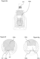
- Figures 1a-c show a first embodiment 100 of a portable gas meter unit configured to be temporarily connected to a vent.
- Figure 1d shows a schematic diagram of the various components of the portable unit shown in figures 1a-c .
- the embodiment gas meter unit comprises:
- This embodiment 100 is a handheld unit and is configured to be used for routine well testing.
- the handheld unit will measure flow, stabilized vent shut-in pressure, and determine alkane hydrocarbon presence/absence by measuring methane concentration by infrared spectroscopy.
- the embodiment comprises three components:
- Figure 1c shows the handheld or portable gas meter 100 in the assembled configuration, where the pressure module 100a is connected to the flow module 100b by connector 140; and the pressure hose 100c is connected to the pressure module 100a by connector 110 (e.g. male 100b and female 100a quick connector).
- connector 110 e.g. male 100b and female 100a quick connector
- the handheld gas meter 100 is configured to hook up (quick connect) to the vent via a flexible pressure hose 108.
- the vent connector comprises the flexible hose vent adaptor 108 with a burst disc 104 which is a non-reclosing pressure relief device that helps protects the system from over- or under-pressurization.
- the burst disc is configured to rupture at 7MPa (this is a regulatory requirement in Alberta).
- the vent adaptor in this case is configured to connect to the casing 199 using a National Pipe Thread (NPT) fitting 102. It will be appreciated that other fittings may be used as required.
- NPT National Pipe Thread
- the burst disc may be configured to rupture at a higher or lower pressure.
- the module connector 140 is provided by the pressure module and the flow module having a complementary shape (and complementary gas channel connectors) to enable the two modules to fit together.
- the first upstream component in the gas meter 100 will be the shut-in pressure module 100a.
- the pressure module 100a is, in this case, configured to be detachable from the flow module 100b. This allows the flow module 100b to be removed (e.g. to allow the shut-in pressure to be determined which may take days or weeks to determine). Because of the time required to perform a shut-in pressure determination, the shut-in pressure may be the last parameter to be measured.
- each pressure module may be associated with an identifier (e.g. an RFID tag or a data signature transmitted between the modules when connected) such that data from different pressure modules may be distinguished by the flow module.
- an identifier e.g. an RFID tag or a data signature transmitted between the modules when connected
- removing the flow module when it is not needed may reduce the risk of theft.
- the pressure module 100a in this case comprises a single inlet to provide fluid communication with the pressure hose 100c.
- a pressure channel 126 runs from this inlet, splits into two sub-channels to two outlets. As will be discussed later, these sub-channels are used to control the gas flow in the flow module.
- the pressure module comprises two shut-in valves 123, 125 (one corresponding to each outlet) for sealing the pressure channel such that it is only open at the inlet.
- each shut in valve has its own valve actuator 122, 124.
- the same actuator may control all outlet shut-in valves.
- shut-in valves 123, 125 When the shut-in valves 123, 125 are closed, pressure from the gas source is allowed to build up within the pressure channel 126 where it may be monitored using the pressure sensor 120. In cases where the flow is low, the pressure build up may take some time (e.g. weeks). Some embodiments may be configured to record the build up of pressure and provide an estimate of the shut-in pressure by extrapolating the build-up pressure data (e.g. by providing an asymptotic value). In other embodiments, the reported pressure may be when a number of successive pressure readings are within a predetermined consistency.
- the measured pressure may be reported with respect to atmospheric pressure which may be recorded using a separate atmospheric pressure sensor 130
- the atmospheric pressure sensor may be used to correlate of intermittent vent flows with atmospheric pressure, as ambient pressure changes can sometimes alter whether or not a vent flow is present (i.e., low pressure vent flows stop flowing during a high pressure weather system).
- the pressure module 100a comprises a wireless antenna 181 for transmitting data to a remote device (e.g. to the disconnected flow module 100b or to a remote server, personal computer/tablet).
- a remote device e.g. to the disconnected flow module 100b or to a remote server, personal computer/tablet.
- Other pressure modules may comprise communication circuitry (e.g. for USB connection, Bluetooth TM and/or GSM connectivity).
- one of the modules may have wireless and the other communication circuitry (Bluetooth etc.) on the same device.
- a pressure module may also comprise a user interface (e.g. simple indicator lights to indicate whether the module is or is not recording and/or a display).
- the gas will then flow into the flow module 100b via the open valve or valves.
- two channels for the gas run in parallel within the flow module 100b: a gas property channel 155 and a flow channel 156 with a flow meter 158.
- the gas property channel 155 and flow channel 156 exit the module via outlet 174.
- the gas property channel 155 comprises a gas composition detector 164.
- the gas composition detector 164 is an IR detector with an IR source 164c and detector 164b. That is, the portion of the gas property channel between the IR source 164c and detector 164b forms a gas cell 164a.
- the IR source 164c and detector 164b are configured to detect the concentration of methane.
- the IR detector is configured to detect IR radiation at a frequency of 3.375 um for C-H bond detector (e.g. for detecting hydrocarbons such as methane) and 3.91um for reference measurement.
- the light source heater 164d is configured to emit light in the IR (blackbody radiator).
- the gas property channel may comprise temperature and/or pressure sensors.
- the gas property channel also comprises an in-line filter positioned before the gas cell 164b. Before and after the inline filter 170, there is positioned a vacuum sensor 168, 169. The purpose of the filter is to remove particles and water that may alter the reading.
- the vacuum sensors 168, 169 are used to indicate when the filter needs to be replaced (maintenance), for example, by measuring a pressure drop exceeding a predetermined threshold across the filter 170.
- the gas property channel 155 also comprises a vacuum unit.
- the vacuum unit in this case is a pump 166 (e.g. a negative displacement pump such as a diaphragm pump, or a positive displacement pumps such as a rotary vane pump, or a scroll pump).
- a pump 166 e.g. a negative displacement pump such as a diaphragm pump, or a positive displacement pumps such as a rotary vane pump, or a scroll pump.
- This purge cycle will be run or repeated until the composition detector 164 records a set number of tests that show consistent results (e.g. 5 consistent results). A determination of the presence and concentration of methane will then be made, and the methane concentration will be used to correct for any error in the flow rate.
- the IR sensors are from Pyreos TM (Part no. PY0261) and the optical cell IR source for both are from Axteris TM (Part no. EMIRS 200 with Reflector 3). It will be appreciated that other IR sources and sensors may be used. In some embodiments, some gas properties may be determined in the pressure and/or flow channels (e.g. temperature).
- the raw flow rate determination is performed by shutting off flow to the gas property channel 155 and directing all flow from the gas source through the flow channel 156. This can be achieved by shutting off shut-in valve 125 in the pressure module 100a and opening valve 123. Before the gas reaches the flow sensor it passes through a particle filter 161 to remove particles and/or water vapour from the flow. This may increase the accuracy of the reading and/or keep the flow sensor clean.
- a low pressure sensor 162 located in the flow channel 156.
- the low pressure sensor is used to determine if the flow channel filter requires maintenance or replacing.
- the gas channels may be formed from stainless steel.
- the flow channel path may be approximately 1 ⁇ 2" (12.7 mm) in diameter where the channel diameter is fixed, and the gas property channel may be approximately 1 ⁇ 8" (3.175 mm) in diameter. It will be appreciated that in different embodiments, the channel sizes may be different (e.g. between 1/16" or 1 ⁇ 8" and 2" (1.59 mm, 3.175 mm and 50.8 mm)).
- the flow meter 158 in the flow channel is a thermal mass flow meter.
- the sensor used for the gas flow is a (MEMS) (microelectromechanical systems) constant temperature anemometer chip.
- MEMS microelectromechanical systems
- such a chip may be Part no. MSF02 from Innovative Sensor Technologies TM . It will be appreciated that other chips may be used, e.g. from a different supplier or custom manufactured.
- the flow through the sensor portion of the channel is controlled by controlling the cross-sectional area of the flow channel 156 using actuator 157.
- the thermal mass flow meter is, in this case, configured to measure a range of flows from 0.01 ml/min to 210,000 ml/min ( ⁇ 300 m 3 /day).
- the apparatus 100 is configured to provide a compensated gas flow measurement by adjusting the raw gas flow measurement based on the determined composition of the gas.
- the unit may be configured to correlate measured raw flow measurements with different compensated gas flow measurements as a function of the measured concentration of methane (or other gas property).
- the gas meter 100 uses mid-range infrared spectroscopy as well as ambient pressure and temperature readings to compensate for different gas properties. This may improve the accuracy of the gas meter.
- Other embodiments may use a different frequency range (e.g. near-IR spectroscopy).
- the flow module in this case comprise communication circuitry 182 (e.g. for USB connection, Bluetooth TM and/or GSM connectivity) to allow data to be transmitted from the device to a remote electronic device (e.g. a server or cloud) for further processing.
- the flow module in this case also comprises a user interface 121 (e.g. simple indicator lights to indicate whether the module is or is not recording and/or a display configured to show remaining battery life; percentage concentration of methane and compensated flow rate).
- the data may be uploaded via wireless transmission to the user's smartphone, tablet or computer using a wireless antenna, and/or via a USB port to use a flash drive or cable link.
- the device may also transmit the gathered data via internet into a central core database for interface by end users.
- the power for the device is primarily from batteries (main battery 127 and possible spare battery 128 connected by battery connector 129) stored in the pressure module 100a. These batteries have terminals which connect to the flow module for powering testing when the pressure module 100a is connected to flow module 100b (e.g. as shown in figure 1c ). This reduces the weight of the flow module 100b and increases flexibility for the pressure module 100a which may be left in situ for days or weeks to perform shut-in pressure measurements.
- the flow module also includes an onboard battery 172 for data viewing; data transfer and/or testing. It will be appreciated that other embodiments may use renewable power sources such a solar power.
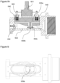
- Figures 2a-c shows a further embodiment which is a broad-spectrum unit 200.
- the broad-spectrum unit is largely similar to the portable unit of figure 1c . However it may be used more specifically for venting well diagnosis, remedial repairs, and post-remedial monitoring.
- this embodiment 200 comprises an isolatable pressure channel 226 with pressure sensor 220 for determining the shut-in pressure.
- the pressure channel 226 may be isolated by actuating the shut-in valves 223 and 225.
- the pressure channel is configured to receive gas from a gas source from a vent adaptor 208 connected to the device by connector 210.
- the gas meter in this case is at least partially powered by battery 272.
- the length of the meter shown in figure 2a may be around 50cm.
- This embodiment also has a flow channel 256 with thermal mass flow meter 258 for determining the flow rate and a gas property channel 255 for determining properties of the gas (e.g. temperature and composition).
- the gas property channel and flow channel exit the gas meter via outlet 274 which in this case comprises a flame arrestor 275.
- the gas property channel comprises a temperature sensor 259 and a composition detector 264 (in this case an IR spectrometer).
- the gas property channel also has a pump 266 to clear the gas property channel prior to determining one or more of the gas properties, and a inline filter 270 for removing particulates and/or water droplets from the flow prior to the gas property sensors 259, 264.
- the inline filter 270 is positioned between two vacuum sensors (one of which 269 can be seen in figure 2b ). The vacuum sensors are used to indicate when the filter needs to be replaced (or have maintenance), for example, by measuring a pressure drop exceeding a predetermined threshold across the filter 270.
- the IR spectrometer composition sensor comprises an IR light source 264c, 264d, a gas cell 264a (formed in flow channel 256) and an IR detector 264b. Whether gas is directed to the flow channel 256 or to the gas property channel 255 is controlled by valves 223, 225 (which in turn are controlled by respective actuators 222, 224).
- the flow channel 256 also comprises a filter 261 for removing particles and water droplets from the gas flow before it reaches the flow sensor 258.
- a low pressure 262 sensor located in the flow channel 256. The low pressure sensor is used to determine if the flow channel filter requires maintenance or replacing.
- a diverting valve may allow gas flow to be directed between the flow and gas property channels successively (e.g. through the gas property channel only for determining composition; and then through the flow channel only for determining the flow rate).
- the pressure channel may be a single channel terminating after the pressure sensor with a diverting valve, the diverting valve outlets being the start of the flow and gas property channels.
- the diverting valve could be turned off to facilitate pressure measurements.
- the pressure channel may be isolated by a single in-line valve.
- gas channels 226, 255, 256 are shown in solid lines and the data links are shown in dotted lines.
- data is transmitted from each of the sensors 220, 259, 264, 258 to a controller 283.
- the controller 283 may then transmit the data to a remote device by, for example, a wireless antenna 281; and/or display data to the user via display 221.
- the optical cell composition detector 264 for determining the composition of the gas is more sophisticated than that of figure 1d and the advanced infrared spectroscopy will give more complete determination of the compounds present by detecting over a broader IR spectra.
- the light source is a broadband source and emits blackbody radiation in the characteristic curve, so data may be obtained for the whole blackbody emission range.
- the data used is in the 2.5 ⁇ m to 5 ⁇ m range.
- the linear array detector may have filters on it that blocks out the other wavelengths, thereby only recording the desired specific range.
- spectral ranges including the near-IR range (0.7-2.5 ⁇ m) and/or far-IR range (5 ⁇ m-1mm) to detect gases.
- Other embodiments may use a photoionization sensor, an infrared point sensor, an infrared imaging sensor, a semiconductor sensor, a laser spectrometer (e.g. a quantum cascade laser spectrometer).
- the IR spectrometer is configured to determine the relative concentrations of the hydrocarbon gas and associated gas component mixture emanating from the subject well (or other gas source).
- the IR sensors are from Pyreos TM (Part no. PY1499). It will be appreciated that other IR sensors may be used.
- the IR detector may comprise multiple detection elements such as a linear pyroelectric array (e.g. a 128 pin array). Other embodiments may use arrays of different sizes (e.g. 256, 512 or more pyroelectric elements).
- Algorithms which may be used include one or more of: Least Square Regression; Classical Least Squares; Inverse Least Squares; Principle Component Regression.
- PCR Principle Component Regression
- PCA Principle Component Analysis
- This device is configured to transmit the data it gathers in real time wirelessly to a smartphone, tablet or laptop onsite. There may be a USB port to use a flash drive or cable link. The device will also transmit the gathered data, real-time via internet into a central core database for interface by its customers.
- the broad-spectrum device can be configured to function as a "sentinel" meter, logging data unattended and utilizing an external power station and uplink module.
- the external power station may comprise a mains supply and/or one or more renewable energy sources.
- the meter In "sentinel” mode, the meter will be able to be accessed remotely to check up on the data it provides and evaluate well conditions without having to be on-site.
- the broad-spectrum unit may also be modular, with separate pressure and flow (and optionally power) modules. That is, the pressure, flow and/or power modules may be separate connectable modular components.
- FIGS 3a and 3b show a variable mass flow sensor (e.g. 158 or 258) in more detail.
- a variable thermal mass flow sensor may form part of, for example, a portable or a broad-spectrum unit.
- variable mass flow sensor comprises:
- the modifiable channel comprises an adjustable obstruction 358a which can be moved within the modifiable channel portion 358b to change the cross-sectional area of a modifiable channel portion.
- the adjustable obstruction is continuously adjustable to provide any arbitrary cross-sectional areas within the range of motion of the adjustable obstruction.
- the adjustable obstruction may be configured to be positionable in a number (2, 3 or more) of discrete positions.
- the motor driving the adjustable obstruction may be a stepper motor.
- the system may be configured to measure the position of the adjustable obstruction.
- the adjustable obstruction in this case is around 7-8cm in length, around 2-4cm in height and around 2-4cm wide.
- the adjustable obstruction in this case comprises a plunger or piston, which is raised or lowered by an actuator 357 (e.g. a motor moving a screw thread).
- the adjustable obstruction 358a is adjusted based on the measured flow rate to increase accuracy.
- the adjustable obstruction is streamlined (e.g. tapered) to promote laminar flow across the flow meter. That is, the upstream edges of the obstruction may be tapered to help reduce resistance and streamline the gas flow.
- the plunger 358 is configured to provide alternative flow paths depending on the position of the plunger. That is, in addition to adjusting the cross-sectional area of the flow path by moving the plunger up and down, the plunger 358 in this case is configured to be positionable in contact with the flow sensor-supporting surface 332. In this configuration, gas flow is not permitted below the plunger but an alternative flow path 354 is provided through the plunger 358a. This may help allow the configuration with the smallest cross-sectional area to be more reproducible as it will be based on the plunger being in contact with the flow sensor-supporting surface 332.
- the alternative flow path 354 in the plunger in this case comprises an inlet closed channel portion, an open channel (sensor) portion and an outlet closed channel portion.
- the open sensor portion of the channel is configured to be enclosed by the sensor supporting surface 332 and the sensor when the plunger is fully down thereby creating a fully closed channel alternative flow path 354 when the plunger is in this configuration.
- the adjustable obstruction or plunger may not have an alternative flow path within the adjustable obstruction or plunger.
- the smallest cross-section configuration may be provided by having just an open channel on the bottom of the adjustable obstruction or plunger, which is enclosed by the sensor supporting surface when the plunger is fully down.
- the adjustable obstruction may be configured to open or close the alternative flow path depending on, for example, the position of the adjustable obstruction.
- the unit will start a flow measurement in a fully opened configuration (largest flow channel). This will establish a baseline flow measurement. If no flow is detected, the channel will be closed in steps. During each step, the flow will be checked until the flow is in range.
- the modifiable channel is configured to have a minimum cross section of between 1 and 5 mm 2 .
- the gas meter is configured to control the cross-sectional area of the modifiable channel based on the gas flow rate such that at high flow rate the cross-sectional area of the modifiable channel is larger than at low flow rate.
- the thermal mass flow meter can measure within a restricted velocity range for a wide range of flow rates. This may increase the accuracy and/or the dynamic range of the device. It will be appreciated that using an adjustable obstruction may allow the cross-sectional area to be modified as a continuous variable.
- Figure 4a and 4b show an alternative way of adjusting the cross-sectional area of a portion of the flow channel 456 not according to the invention.
- the modifiable channel portion comprises multiple sub-channels 456a, 456b, 456c in parallel, and wherein the total cross-sectional area of the channel can be controlled by selectively obstructing one or more of the sub-channels.
- the sub-channels can be obstructed by closing valves 431a, 431b over one or more of the sub-channels. Closing the valves reduces the cross-sectional area of the modifiable portion of the flow channel.
- the third channel 431c in this case, is never occluded in this embodiment because the thermal mass flow meter 458b is located in the third channel.
- the first sub-channel 456a is occluded which directs the flow through the second 456b and third 456c flow sub-channels.
- first 456a and second 456b flow channels are occluded which directs the flow through the third flow sub-channel only.
- the valves in this embodiment are configured when closed to direct flow smoothly to the remaining open sub-channels so as not to restrict flow.
- Figure 5a and 5b show an alternative way of adjusting the cross-sectional area of a portion of the flow channel 556 using sub-channels not according to the invention.
- the modifiable channel portion comprises multiple sub-channels 556a, 556b in parallel such that the total cross-sectional area of the channel can be controlled by selectively obstructing the sub-channels 556a, 556b so that all flow is directed through a single sub-channel.
- the selective obstruction is performed by a diverting valve 531a.
- the sub-channels can be obstructed by closing the diverting valve 531a over all but one of the sub-channels 556a, 556b.
- the first sub-channel 556a is occluded which directs the flow through the second flow sub-channel 556b.
- the second flow channel 556b is occluded which directs the flow through the first flow sub-channel 556a only.
- each there is a thermal mass flow meter 558b, 560b positioned in each sub-channel and each sub-channel has a different cross-sectional area which means that different sub-channels provide different cross-sectional areas.
- thermal mass flow meters may be placed in series as well as in parallel.
- a thermal mass flow sensor may be positioned in advance of the sub-channel portion to be able to measure the mass flow through the full-bore flow channel.
- sub-channels may allow the cross-sectional area to be adjusted or modified to one of a set of discrete values.
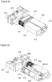
- Figures 6a and 6k show a variable mass flow module.
- the structure of the module is similar to that of figure 3b .
- Such a variable thermal mass flow sensor may form part of, for example, a portable or a broad-spectrum unit.
- the gas meter is configured to allow two positions of the adjustable obstruction.
- variable mass flow sensor comprises:
- the system is configured to be modifiable between two discrete (e.g. binary) positions. This may help ensure that the cross-sectional area is more reproducible by limiting the number of options available.
- the sensor in this case consisted of a PCB mounted MEMs chip attached to an aluminum body, which houses an adjustable obstruction 658a (a plunger in this case).
- the plunger can be actuated so that it sits firmly against the chip/PCB surface or lifted away from the chip (e.g. by up to 9mm).
- the MEMs chip is attached to the PCB by wires, which are held in place by a globule of epoxy.
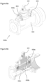
- the plunger is configured to be manually actuated through rotation of manual actuator 651.
- the manual actuator in this case comprises a male helical screw, which engages with a corresponding female helical screw with a U-shaped plunger carrier 652 which is attached to the plunger.
- the plunger 658a moves within the channel.
- other manual actuators may be used such as levers.
- Other embodiments may be configured to change configurations in response to a user input (e.g. a switch, using computer user interface).
- the plunger carrier is resiliently attached to the plunger via a number of springs (a series of Belleville washers 643 in this case). These help maintain the plunger in alignment as it is being moved between positions. It will be appreciated that other two-position embodiments may be configurable automatically.
- the plunger When in the constricted configuration the plunger abuts the opposing surface of the channel. When in the open configuration, the top of the plunger abuts one or more stops 653.
- the stops in this case are screw heads mounted in the body 644 of the flow module and which lie over the opening in which the plunger 653 is inserted.
- the alternative flow path 654 in the plunger in this case comprises an inlet closed channel portion, an open channel (sensor) portion and an outlet closed channel portion.
- the open sensor portion of the channel is configured to be enclosed by the sensor supporting surface 632 and the sensor when the plunger is fully down thereby creating a fully closed channel alternative flow path 654 when the plunger is in this configuration.
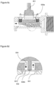
- the MEMs chip consists of 5 RTDs (resistance temperature detectors) elements aligned in a row on a glass substrate.
- the 5 elements are as follows: sensor 1 (663a); sensor 2 (663b); sensors 3 and 4 (663c,d) that act in consort in this embodiment; and sensor 5 (663e).
- the sensing elements can either act as small heaters or as temperature sensors depending on the amount of electrical power provided to them.
- One upstream sensor (sensor 1 (663a) in the figure 4f) serves as an ambient gas flow temperature sensor and reads the temperature of the gas as it comes out of the vent.
- the four downstream elements (sensor 2-5 (663b-e) in the figure 4f) are located over a very thin backing of glass to reduce the thermal capacitance of the sensors and increase the response speed.
- the glass may be around 1-2 millimeters or less in thickness.
- the MEMs chip can operate in one of two modes: calorimetry mode and anemometer mode (or Constant Temperature Anemometry, CTA).
- calorimetry mode and anemometer mode (or Constant Temperature Anemometry, CTA).
- CTA Constant Temperature Anemometry
- sensor elements 3 and 4 (663c,d) are heated with between 5-10mW of power.
- the heaters are kept at a constant temperature above the ambient gas temperature. This helps ensure that the heaters are neither going to burn out in no flow nor be cooled too much in high flow.
- Sensor elements two and five measure the temperature of the gas on either side of the heating elements. If there is flow present the downstream sensor five will be at a higher temperature then sensor two since the heat from the heater elements will be blown downstream. From the temperature difference of sensor elements two and five the flowrate can be determined. Due to the very thin substrate under these four elements the heat that is transferred from the heater to the sensor is transferred almost entirely though the gas and not through the substrate, this make the sensor much more sensitive to very small gas flows. This configuration is very sensitive to low flow but the heat can be blown away too fast in high flow to sufficiently heat the downstream sensor. Because of the calorimetry configuration is less applicable to large flows.
- sensor elements three and four are kept at a constant temperature above the ambient gas with a feedback loop.
- the flow rate is measured by determining how much power is provided to the two sensors to keep them at an elevated temperature. As the flow rate increases more heat is blown off the sensor elements so the power required to keep them at a constant temperature increases.
- This configuration is not sensitive to very low flows but allows measurement of high flows. Sensors two and five are not used in this configuration.
- a Constant Temperature Anemometer Configuration CTA
- a Constant-Power Anemometer Configuration CPA
- Constant-temperature anemometers may be advantageous in certain scenarios because of their high-frequency response, low electronic noise level, immunity from sensor burnout when airflow suddenly drops, compatibility with hotfilm sensors, and their applicability to liquid or gas flows.
- Constant-power anemometers generally do not have a feedback system and so may be easier to construct. Temperature is simply proportional to flowrate. However, although they can be used, they are generally less popular because their zero-flow reading is not stable, temperature and velocity response is slow, and temperature compensation is limited.
- the overlap between calorimeter and CTA modes sensing range is approximately 25% of the full calorimeter scale (see Figure 6I ). This overlap is not dependent on the plunger height.
- the sensing range signal overlap between the plunger fully down and fully up is approximately 5% the plunger up calorimeter full scale value. Since all the measurement ranges overlap, the sensor may accurately measure the full range of flow from one bubble in ten minutes to over 300 cubic meters per day.
- the gas meter is configured to determine calorimeter and CTA values all of the time. That is, the chip can simultaneously be both a calorimeter and anemometer.
- the gas meter decides (e.g. with a state machine) which value to use based on a predetermined criterion. For example, the criteria may be based on a predetermined set point related to a crossover in sensitivity at a particular flow rate value. It will be appreciated that the output value may be calculated based on both the determine calorimeter and CTA values.
- the range overlap between the plunger fully down and fully up is determined by the maximum 1 inch (25.4 mm) of H 2 O of back pressure when measuring low flows with the plunger down.
- the flow measurement still has plenty of measurement range left when the plunger is lifted to keep the back pressure low.
- Two plunger states may greatly simplify the plunger actuation and positioning requirements. This will increase the repeatability of the sensor since mid-position plunger locations are not required so the plunger can be moved until it hits the hard stops at the top and bottom of its travel. This may help remove much of the uncertainly about maintaining consistent flow channel size between measurements.
- This device was tested and should be able to measure flow of less than one bubble in ten minutes.
- the low flow apparatus used to test this device can reliably create flows only greater than one bubble in three minutes so direct measurement of flow at the device's sensitivity limit was not possible.
- Mathematical extrapolation was used from the experimental results to approximate the flow sensitivity of the device down to the minimum level.
- the minimum detectible flow signal was defined as the signal strength that is two standard deviations of the signal noise above the zero point average. This allows a 95% confidence level that if the signal is at this level it represents an actual flow.
- the theoretical minimum detectible flow can be improved by taking a moving average of the raw signal, which serves to reduce the high frequency noise. Taking a relatively short moving average of 1 and 5 seconds a detectible flow of 0.054 and 0.027 bubbles per minute could be resolved with the current prototype. This corresponds to one bubble in ⁇ 18min and ⁇ 37min respectfully. These values are accurate assuming that the true zero point is known exactly. There will be slight drifts in the zero point due to plunger pressure, time between calibration and temperature of the device. Most of these zero point errors can be calibrated out but some will always remain. Based on these results however even with slight zero point drifts there is a high confidence that the device should be able to detect flows of one bubble in ten minutes.
- the dynamic range of the flow sensor is the difference between the minimum and maximum flow the sensor can resolve. As discussed above the minimum flow of one bubble in ten minutes (approximately 0.04ml/min) can be detected at the low end. At the high end flows in excess of 300 cubic meters per day (210,000ml/min) can be measured.
- Figure 6I shows the detectable signal for a range of flow rates in calorimeter and anemometer modes. Calorimeter mode is shown as diamonds (values correspond to left y-axis) and anemometer (or CTA) mode is shown as squares (values correspond to right y-axis).
- Test equipment to accurately produce flows in the high flow range was not available at the time of testing so high flow values were simulated.
- the sensor response to high flows can be simulated. From these simulations the full dynamic range required of the sensor from 0.04ml/min to 210,000 ml/min can be easily achieved. Measurement of flows higher than 210,000ml/min can be achieved.
- the back pressure may become the limiting factor so it is expected that the full flow measurement range of the device will not be limited by flow measurement but by back pressure. Controlling the configuration of the channel will mitigate this.
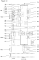
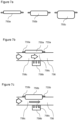
- Figures 7a-7e shows an embodiment of a gas meter comprising:
- figure 7a is a schematic side view of a number of plungers, each configured to provide a different cross sectional area to the channel.
- Figures 7b and c are perspective views of an embodiment, which comprises one of the plungers of figure 7a .
- the channel comprises a replaceable channel module portion (three replaceable channel module portions 750a-c are shown schematically in figure 7a ).
- the replaceable channel module portion is configured to provide the modifiable channel portion with a predetermined and fixed cross-sectional area such that the cross-sectional area of the channel can be modified by replacing the replaceable channel module portion with another the replaceable channel module portion with a different predetermined and fixed cross-sectional area. That is, each module has a fixed and predetermined cross sectional area.
- the main gas meter unit (comprising the body 744 and PCB carrier 745) comprises an open channel and the replaceable channel module portion comprises a fixed plunger 750a-c and at least one connector 733a,b for fixing to the main gas meter unit.
- the replaceable channel module portion 750a-c is connected to the main gas meter unit via the connectors 733a,b, the cross-sectional area of the modifiable channel portion 758c is provided with a predetermined cross-sectional area.
- the replaceable channel module portions also comprise a seal 742 for ensuring a good connection with the body 744 of the gas meter flow module.
- the gas meter may determine the predetermined cross-sectional area in a number of ways.
- the main unit may store information associating particular modules with particular predetermined cross-sectional areas. When the module is identified, the main unit may be configured to look-up the associated cross-sectional area value.
- the replaceable channel module portion can be identified using one or more of: a user entering which module has been inserted; the reading a code such as an RFID code, a bar code and/or an optical code (the reader may be on the main unit and the code on the plunger or vice versa).
- the system may be configured to detect the position of the plunger using proximity sensors, for example, mechanical posts with capacitive sensors on the plunger body. It will be appreciated that the distance determined may be associated with one of a discrete number of possibilities. For example, if the sensor determined that the plunger was 24(t1) mm away but the modules available were 5, 10 and 25 mm, the system may determine that the distance is 25 mm based on the available modules. Alternatively or in addition, if the determined plunger distance is found not to correspond to one of the available replaceable channel module portions (e.g. a distance of 20(t1) mm was measured), it may provide a warning to the user (e.g. to check that the replaceable channel module portion has been correctly connected).
- proximity sensors for example, mechanical posts with capacitive sensors on the plunger body. It will be appreciated that the distance determined may be associated with one of a discrete number of possibilities. For example, if the sensor determined that the plunger was 24(t1) mm away but the modules available were 5, 10 and 25 mm, the
- the connectors in this case comprise screws.
- the plunger (or other modular obstruction) may comprise clip or quick-release connectors.
- the replaceable channel module portion may comprise stops, which are configured to rigidly abut a rigid portion of the main gas meter unit to ensure that the cross-sectional area of the modifiable channel portion is reproducible when replacing modules.
- the PCB carrier in this case comprise metal. It is configured to house the PCB 758f, which in turn supports the sensor chip 758b.
- the gas meter may comprise a composition analyser configured to determine the make-up of the gases within the gas flow (e.g. for compliance purposes or for refining the flow rate measurements).
- gas composition detector 864 An embodiment of the gas composition detector 864 is shown in figures 8a-b . Some embodiments may be configured to determine the level of gaseous hydrocarbons present in the flow. Methane is expected to be the major hydrocarbon but other higher order hydrocarbon gases may be present. In some cases, the sensor may be configured to read total hydrocarbon levels. In other embodiments, the sensor may also be configured to distinguish between the different hydrocarbons.
- the low-level detection limit may be less than 1000ppm.
- the sensor may have a dynamic range of 1,000-1,000,000 ppm with a sensitivity of around 100 ppm.
- the gas composition detector 864 comprises a mid-infrared thermopile based sensor.
- the detection principle is that a specific gas absorbs light (in a small wavelength range) in proportion to the gas concentration. The higher the concentration of the gas the more light it will absorb.
- This analyser consists of a sensor 864b, which can detect general light intensity.
- a filter 864e placed over the sensing element allows only a small range of wavelengths to pass through it and be measured. This allows the sensor 864b to be tuned to a specific gas detection wavelength.
- the sensor is illuminated with a pulsed broadband mid infrared source 864b with shines through the gas sample within analyser channel 864a.
- This channel has an inlet and an outlet for allowing flow through channel 864a Depending on the hydrocarbon concentration different amounts of light in the 3.2-3.5 ⁇ m wavelength region is absorbed by the gas.
- the sensor from which a concentration can be derived measures the absorption of light.
- the senor has two elements, one tuned to a wavelength of 3.375 ⁇ m (190nm width) and the other tuned to 3.91 ⁇ m (90nm width).
- the 3.375 ⁇ m channel is tuned to the wavelength of light absorbed by the hydrocarbon the other is generally outside of the absorption wavelength of most gases and is used to calibrate for the overall light intensity of the source.
- the sensor used for this embodiment is the PY-ITV-DUAL-TO39 (3+1) manufactured by Pyreos Sensing Solutions TM .
- a gas cell which is a 5cm long brass tube 9mm diameter through which the gas flows.
- the gas cell has sapphire windows 864f,g on each end to contain the gas and allow the IR light into and out of the cell.
- the inside of the cell is polished to increase the amount of light that is received by the sensor.
- Both the light source and the sensor were mounted to prototype development boards provided by Pyreos Sensing Solutions TM . These boards allowed software control and recording of the various parameters of the source and sensor.
- the senor could detect methane concentrations as low as 100 ppm using a 5 cm long gas cell. A smaller detection limit could be achieved if a longer gas cell was used. This however would likely result in the higher concentrations not being resolved. The longer gas cell would absorb the light passing through so much that too little light would make it through the cell to be read by the sensor.
- the processor may be configured to store data, which relates the zero-point reading to the temperature. This data could be used to compensate for temperature changes at the time of measurement.
- some embodiments may be to also specifically detect carbon dioxide so the under-prediction of hydrocarbons can be removed by calibration.
- Four-channel sensors are available that would be able to sense the required gases to enable this calibration.
- a gas property sensor may comprise a photoionization sensor, an infrared point sensor, an infrared imaging sensor, a semiconductor sensor, a laser spectrometer (e.g. a quantum cascade laser spectrometer) and/or a mass spectrometer.
- the gas analysis algorithm in this case uses the Beer-Lambert absorption principle, which states that a certain amount of light at a specific wavelength will be absorbed by a species with an absorption feature at the same wavelength as the emitting light. The magnitude of the response will be equal to the emitted light, the amount of molecules the light passes through (path length and concentration), and the absorption coefficient of the molecular transition at that wavelength (line strength).
- certain embodiments may be configured to use a quad detector in the mid infrared to determine the concentration of methane, non-methane hydrocarbons, CO2, and a reference line for light level.
- Other embodiments may be configured to use different channels.
- the absorption-spectrum gas composition detection algorithm is configured to perform the following:
- a microcontroller is configured to emit a 10 Hz drive signal at 3.3 V to periodically apply power to the emitter/heater device. Additionally, the MCU drives a voltage amplifier through a DAC to adjust the maximum voltage applied across the emitter terminals. This allows the response of the detectors to be determined in the absence of emitted light. This baseline can be accounted for so that the difference between the sensor response with the emitter being on and off being used to determine the concentration of gas.
- gas meters such as these could be used in, for example, retail gas stations, measuring and monitoring gas storage tank venting constituents. That is, the gas meters described herein may be used in any instance or environment whereby venting fugitive gas emissions should be or need to be quantified and qualified. Indeed, the variable flow meter that is incorporated in the embodiments described above may have a wide variety of additional uses outside of the realm of SCVF and well remediation operations. That is, the flow meter will be able to be adapted anywhere where a varying flow rate will need to be assessed.
- the technology may also be incorporated directly into wellheads to remotely run SCVF checks and mitigate the expense of sending personnel into the field to regularly monitor wells.
- the sophisticated spectral component may also be modular.
- the flow or pressure modules may be configured to allow different gas property modules to be attached (e.g. in different combinations).
- a user may by a separate gas property module configured to detect a particular gas (e.g. methane or gasoline fumes); or be able to replace a simple IR spectrometer with a more sophisticated IR spectrometer (e.g. with greater sensitivity or broader spectrum). That is, the spectral module would be a "plug-and-play" module by itself or possibly connected to the basic portable unit.
- the gas property channel may form part of a gas property module with is separate from the flow module.
- a further component would be a self-contained “solar” or equivalent rechargeable battery pack system for broad-spectrum or sentinel monitoring applications. Again, the battery pack would be a simple "plug-and-play" component to the basic unit.
- embodiments of the present technology may be used for gas sinks.
- embodiments may be used to determine the flow into the vent and the shut-in pressure (negative with respect to atmospheric).
- the technology may be used by oil and gas companies in well abandonment operations; more specifically proving the device with SCVF detection, evaluation, and remediation.
- Regulatory Well Monitoring the technology may be used to monitor and report SCVF as directed by AER Annual Well Inspections Directive and with the regulated requirement of 90 day SCVF testing and reporting window for new drills. It is projected that all oil company field offices may have more than one monitor for each field office.
- Third Party Service Providers the technology may be used by well testing and monitoring companies provide testing services to oil and gas companies for convenience with the regulatory well monitoring requirements.
- the device and web-based data access will be made available to these potential clients for their respective customers.
- Environmental & Reclamation Companies As with the well testing and monitoring companies above, the device and web-based data access will be made available Environmental & Reclamation Companies for their respective customers.
- Petroleum Sector Expansion - Downstream Petroleum retailers store bulk volumes of fuel products in aboveground or underground tanks, vented to atmosphere. It is a regulatory requirement of the environmental regulator of each province to monitor, record and verify fuel volumes from delivery to sales. Each retailer must record a "shrinkage volume factor" which must correct and prove any volumetric discrepancy is due to fugitive vapour venting to the atmosphere and not a liquid fuel leak. Manually dipping the bulk fuel tanks and arithmetically calculating the net fuel volumes is the current method of recording and reporting. A "rule-of-thumb" shrinkage factor is given to each retailer by the fuel supplier to attempt to correct any volumetric discrepancy. The present technology may be a more accurate determination of fugitive emissions venting from fuel tankage.
- the present technology may be applied to other industries where fugitive gas emissions are vented to atmosphere such as breweries, distilleries, pulp and paper, and mining industries.
- devices disclosed herein may perform one of more of the following: optically detect the presence of, measure the flow rate of, and identify the characteristics of venting fugitive gas emissions.
- the device may provide a spectral analysis of emission gas constituents; selective detection of the presence of venting hydrocarbons; measurement of venting emissions flow rates, the measurement of shut-in and flowing venting system pressures and/or the venting system temperatures.
- the flow rates may be corrected, relative to the detection of the gas constituents and standard temperature and pressure (STP).
- Disclosed devices may be configured to collect such data electronically and transmit via various telemetry systems, to a secure remote data network for reporting, access, evaluation, real-time monitoring and archiving as required.
Landscapes
- Physics & Mathematics (AREA)
- Fluid Mechanics (AREA)
- General Physics & Mathematics (AREA)
- Geology (AREA)
- Mining & Mineral Resources (AREA)
- Life Sciences & Earth Sciences (AREA)
- Engineering & Computer Science (AREA)
- Environmental & Geological Engineering (AREA)
- Geophysics (AREA)
- General Life Sciences & Earth Sciences (AREA)
- Geochemistry & Mineralogy (AREA)
- Measuring Volume Flow (AREA)
- Other Investigation Or Analysis Of Materials By Electrical Means (AREA)
Claims (14)
- Gaszähler, der umfasst:einen Kanal (156; 256; 356; 656; 756), der einen veränderbaren Kanalabschnitt (158; 358; 658; 758) mit einer veränderbaren Querschnittsfläche umfasst, wobei die Querschnittsfläche des veränderbaren Kanalabschnitts (158; 358; 658; 758) durch Einstellen der Position eines Kolbens veränderbar ist, um die Geschwindigkeit durch den veränderbaren Kanalabschnitt (158; 358; 658; 758) für eine gegebene Durchflussrate zu steuern; undeinen thermischen Massendurchflussmesser, der in dem veränderbaren Kanalabschnitt angeordnet ist und der die Massendurchflussrate misst, indem er einen Teil des strömenden Fluids erhitzt und dann aufzeichnet, wie diese Wärme durch die Strömung verteilt wird; und wobei der Gaszähler ferner dadurch gekennzeichnet ist, dass:
der Gaszähler so eingerichtet ist, dass er in vier Zuständen arbeitet, wobei die vier Zustände umfassen:einen ersten Zustand, in dem der Kolben ganz unten ist, und sich der thermische Massendurchflussmesser in einem Kalorimeter-Sensormodus befindet;einen zweiten Zustand, in dem der Kolben ganz unten ist, und sich der thermische Massendurchflussmesser in einem Konstanttemperatur-Anemometer-Sensormodus befindet;einen dritten Zustand, in dem der Kolben ganz oben ist, und sich der thermische Massendurchflussmesser im Kalorimeter-Sensormodus befindet; undeinen vierten Zustand, in dem der Kolben ganz oben ist, und sich der thermische Massedurchflussmesser im Konstanttemperatur-Anemometer-Sensormodus befindet,wobei die ganz oben und ganz unten Positionen des Kolbens durch den Bewegungsbereich des Kolbens innerhalb des veränderbaren Kanalabschnitts definiert sind, und wobei der veränderbare Kanalabschnitt dazu eingerichtet ist, in allen vier Zuständen einen Fluidstrom zu ermöglichen. - Gaszähler nach Anspruch 1, wobei der Gaszähler dazu eingerichtet ist, die Querschnittsfläche des veränderbaren Kanalabschnitts (358; 658; 758) auf der Grundlage der Gasdurchflussrate so zu steuern, dass bei hoher Durchflussrate die Querschnittsfläche des veränderbaren Kanalabschnitts (358; 658; 758) größer ist als bei niedriger Durchflussrate.
- Gaszähler nach einem der Ansprüche 1-2, wobei der Gaszähler dazu eingerichtet ist, die Querschnittsfläche des einstellbaren Kanals auf der Grundlage der Massendurchflussrate zu steuern, der von dem in dem einstellbaren Kanal angeordneten thermischen Massendurchflussmesser gemessen wird.
- Gaszähler nach einem der Ansprüche 1-3, wobei der veränderbare Kanalabschnitt (158; 358; 658; 758) stromlinienförmig ist, um eine laminare Strömung durch den Durchflussmesser zu fördern.
- Gaszähler nach einem der Ansprüche 1-4, wobei der Durchflussmesser dazu eingerichtet ist, einen Gasdurchfluss zu messen, um eine Rohgasdurchflussmessung bereitzustellen, und wobei das Gasmessgerät ferner umfasst:mindestens einen Gaseigenschaftssensor (259), der zur Bestimmung einer oder mehrerer Eigenschaften des Gases und der Umgebung eingerichtet ist,wobei der Gaszähler dazu eingerichtet ist, eine kompensierte Gasdurchflussmessung bereitzustellen, indem er die Rohgasdurchflussmessung auf der Grundlage der bestimmten einen oder mehreren Eigenschaften des Gases und der Umgebung anpasst.
- Gaszähler nach Anspruch 5, wobei die eine oder die mehreren bestimmten Eigenschaften des Gases eine oder mehrere der folgenden Eigenschaften umfassen: die Temperatur des Gases; den Druck des Gases; die Umgebungstemperatur; den atmosphärischen Druck; und die Zusammensetzung des Gases.
- Gaszähler nach einem der Ansprüche 5-6, wobei mindestens ein Gaseigenschaftssensor (259) eine oder mehrere der folgenden Komponenten umfasst: ein IR-Spektrometer; einen Temperatursensor; und einen Drucksensor.
- Gasmessgerät nach einem der Ansprüche 5-7, wobei der mindestens eine Gaseigenschaftssensor (259) ein IR-Spektrometer umfasst, das dazu eingerichtet ist, eine oder mehrere der folgenden Größen zu bestimmen:die Konzentration von Nicht-Kohlenwasserstoffen im Gas;die Konzentration von Methan im Gas; unddie Konzentration von Kohlenwasserstoffen im Gas.
- Gaszähler nach einem der Ansprüche 5-8, wobei der Gaszähler einen Strömungskanal (156; 256) und einen Gaseigenschaftskanal (155; 255) umfasst, wobei der Gaszähler eingerichtet ist zur Bestimmung:
der Durchflussrate aus dem durch den Strömungskanal geleiteten Gasdurchfluss und mindestens eine Gaseigenschaft aus dem durch den Gaseigenschaftskanal geleiteten Gassdurchfluss. - Gasmessgerät nach einem der Ansprüche 1-9, wobei die Überlappung zwischen dem Kalorimeter- und dem CTA-Betriebsarten Messbereich 25 % der vollen Kalorimeterskala beträgt.
- Gaszähler nach einem der Ansprüche 1-10, wobei die Überlappung des Messbereichssignals zwischen dem Kolben ganz unten und ganz oben 5 % des Kalorimeterendwerts des Kolbens in der oberen Position beträgt.
- Gaszähler nach einem der Ansprüche 1-11, wobei die Positionen des Kolbens ganz oben und ganz unten durch harte Anschläge am oberen und unteren Ende seines Weges definiert sind.
- Gaszähler nach einem der Ansprüche 1-12, wobei der Gaszähler dazu eingerichtet ist, auf der Grundlage eines vorbestimmten Kriteriums zu bestimmen, ob ein Kalorimeter-Sensorwert oder ein Konstanttemperatur-Anemometer-Sensorwert zu verwenden ist.
- Verfahren zur Bestimmung der Durchflussrate von Gas, wobei das Verfahren umfasst:Strömenlassen des Gases durch einen Kanal (156; 256; 356; 656; 756), wobei der Gaskanal einen modifizierbaren Kanalabschnitt (158; 358; 658; 758) mit einer modifizierbaren Querschnittsfläche aufweist, wobei die Querschnittsfläche des Kanalabschnitts (158; 358; 658; 758) durch Einstellen der Position eines Kolbens modifizierbar ist, um die Geschwindigkeit durch den modifizierbaren Kanalabschnitt (158; 358; 658; 758) für eine gegebene Durchflussrate zu steuern;Messen des Massendurchflusses durch den veränderbaren Teil unter Verwendung eines thermischen Massendurchflussmessers durch Erhitzen eines Teils der strömenden Flüssigkeit und anschließendes Aufzeichnen, wie diese Wärme durch die Strömung verteilt wird; undEinstellen der Querschnittsfläche des veränderbaren Teils und des thermischen Massendurchflussmessers zwischen vier Zuständen, wobei die vier Zustände umfassen:einen ersten Zustand, in dem der Kolben ganz unten ist und sich der thermische Massendurchflussmesser in einem Kalorimeter-Sensormodus befindet;einen zweiten Zustand, in dem der Kolben ganz unten ist und sich der thermische Massendurchflussmesser in einem Konstanttemperatur-Anemometer-Sensormodus befindet;einen dritten Zustand, in dem der Kolben ganz oben ist und sich der thermische Massendurchflussmesser im Kalorimeter-Sensormodus befindet; undeinen vierten Zustand, in dem der Kolben ganz oben ist und sich der thermische Massedurchflussmesser im Konstanttemperatur-Anemometer-Sensormodus befindet,wobei die ganz oben und ganz unten Positionen des Kolbens durch den Bewegungsbereich des Kolbens innerhalb des veränderbaren Kanalabschnitts definiert sind, und wobei der veränderbare Kanalabschnitt dazu eingerichtet ist, in allen vier Zuständen einen Fluidstrom zu ermöglichen.
Applications Claiming Priority (2)
| Application Number | Priority Date | Filing Date | Title |
|---|---|---|---|
| US201662433112P | 2016-12-12 | 2016-12-12 | |
| PCT/CA2017/051499 WO2018107280A1 (en) | 2016-12-12 | 2017-12-12 | Gas meter and associated methods |
Publications (3)
| Publication Number | Publication Date |
|---|---|
| EP3551970A1 EP3551970A1 (de) | 2019-10-16 |
| EP3551970A4 EP3551970A4 (de) | 2020-07-22 |
| EP3551970B1 true EP3551970B1 (de) | 2024-07-17 |
Family
ID=62489070
Family Applications (1)
| Application Number | Title | Priority Date | Filing Date |
|---|---|---|---|
| EP17880282.3A Active EP3551970B1 (de) | 2016-12-12 | 2017-12-12 | Gaszähler und zugehörige verfahren |
Country Status (6)
| Country | Link |
|---|---|
| US (3) | US10684154B2 (de) |
| EP (1) | EP3551970B1 (de) |
| AU (3) | AU2017376976B2 (de) |
| CA (3) | CA3190515C (de) |
| MX (2) | MX2019006808A (de) |
| WO (1) | WO2018107280A1 (de) |
Families Citing this family (25)
| Publication number | Priority date | Publication date | Assignee | Title |
|---|---|---|---|---|
| US10576514B2 (en) | 2013-11-04 | 2020-03-03 | Loci Controls, Inc. | Devices and techniques relating to landfill gas extraction |
| US10029290B2 (en) | 2013-11-04 | 2018-07-24 | Loci Controls, Inc. | Devices and techniques relating to landfill gas extraction |
| US10576515B2 (en) | 2013-11-04 | 2020-03-03 | Loci Controls, Inc. | Devices and techniques relating to landfill gas extraction |
| US10705063B2 (en) * | 2016-03-01 | 2020-07-07 | Loci Controls, Inc. | Designs for enhanced reliability and calibration of landfill gas measurement and control devices |
| CA3240725A1 (en) | 2016-03-01 | 2017-09-08 | Loci Controls, Inc. | Designs for enhanced reliability and calibration of landfill gas measurement and control devices |
| US20190226896A1 (en) * | 2018-01-22 | 2019-07-25 | Feng Zhang | Novel Electronic Gas Meter |
| WO2019173132A1 (en) | 2018-03-06 | 2019-09-12 | Loci Controls, Inc. | Landfill gas extraction control system |
| US10882086B2 (en) | 2018-10-01 | 2021-01-05 | Loci Controls, Inc. | Landfill gas extraction systems and methods |
| CN111221289B (zh) * | 2019-04-09 | 2021-07-27 | 国网福建省电力有限公司 | 电表数据交互系统及方法 |
| CA3051376C (en) | 2019-08-06 | 2020-04-28 | Surface Solutions Inc. | Methane monitoring and conversion apparatus and methods |
| US11150120B2 (en) * | 2019-09-22 | 2021-10-19 | Applied Materials, Inc. | Low temperature thermal flow ratio controller |
| US11883864B2 (en) | 2020-01-29 | 2024-01-30 | Loci Controls, Inc. | Automated compliance measurement and control for landfill gas extraction systems |
| US12110769B2 (en) | 2020-03-18 | 2024-10-08 | Moneyhun Equipment Sales & Service Co., Inc. | Fugitive gas remediation system |
| US11512990B2 (en) * | 2020-07-01 | 2022-11-29 | Wisenstech Ltd. | Gas meter with thermal time-of-flight sensing |
| US11623256B2 (en) | 2020-07-13 | 2023-04-11 | Loci Controls, Inc. | Devices and techniques relating to landfill gas extraction |
| US12090532B2 (en) * | 2020-07-13 | 2024-09-17 | Loci Controls, Inc. | Devices and techniques relating to landfill gas extraction |
| AU2021390516B2 (en) | 2020-12-03 | 2025-10-09 | Loci Controls, Inc. | Greenhouse gas emissions control |
| USD988163S1 (en) * | 2021-04-13 | 2023-06-06 | Loci Controls, Inc. | Gas composition detection device |
| USD988893S1 (en) * | 2021-04-13 | 2023-06-13 | Loci Controls, Inc. | Gas composition detection device and pipe assembly |
| JP2023017252A (ja) * | 2021-07-26 | 2023-02-07 | アズビル株式会社 | 流量計 |
| US20250116589A1 (en) * | 2022-03-25 | 2025-04-10 | Schlumberger Technology Corporation | Systems and methods for quantifying and monitoring hydrocarbon volumes and surface gas emissions for wireline formation testing |
| CN115165043B (zh) * | 2022-05-13 | 2023-09-26 | 北京市燃气集团有限责任公司 | 一种煤气体积计量误差的监测系统、方法、装置 |
| KR102924171B1 (ko) * | 2024-02-14 | 2026-02-09 | 주식회사 공감센서 | 대기질 측정장치 |
| JP7597972B1 (ja) | 2024-03-27 | 2024-12-10 | 旭化成エレクトロニクス株式会社 | 制御装置、センサ装置、および方法 |
| CN119178478B (zh) * | 2024-11-19 | 2025-02-28 | 潍坊市计量技术研究院 | 一种高精度多通道超声波流量计 |
Family Cites Families (24)
| Publication number | Priority date | Publication date | Assignee | Title |
|---|---|---|---|---|
| JPS517092A (en) * | 1974-07-08 | 1976-01-21 | Sumitomo Bakelite Co | Anteiseio kairyoshita jiseizairyokeigurafutojugofukugotai |
| JPS5180670A (ja) | 1975-01-11 | 1976-07-14 | Fuji Industries Co Ltd | Kakupaipunipiasubaaringuohodokosu renzokujidokakoki no kanagatasochi |
| JPS60209116A (ja) | 1984-03-31 | 1985-10-21 | Keihin Seiki Mfg Co Ltd | 流量計 |
| JPH05107092A (ja) | 1991-10-18 | 1993-04-27 | Tokico Ltd | 熱式流量計 |
| JP3211317B2 (ja) | 1991-12-27 | 2001-09-25 | 株式会社デンソー | 混合ガスの計測方法及び装置 |
| US5297427A (en) | 1992-09-03 | 1994-03-29 | Alicat Scientific, Inc. | Wide-range laminar flowmeter |
| US6319191B1 (en) | 1998-03-26 | 2001-11-20 | Precision Medical Devices, Inc. | Implantable body fluid flow control device |
| US6119710A (en) * | 1999-05-26 | 2000-09-19 | Cyber Instrument Technologies Llc | Method for wide range gas flow system with real time flow measurement and correction |
| JP4298077B2 (ja) * | 1999-08-03 | 2009-07-15 | 愛知時計電機株式会社 | 気体流量計 |
| DE10000178A1 (de) | 2000-01-05 | 2001-07-12 | Mueller Friedrich | Einrichtung zum Überprüfen und/oder Beeinflussen der Strömung in einem Fluid |
| US7536908B2 (en) * | 2004-03-11 | 2009-05-26 | Siargo, Ltd. | Micromachined thermal mass flow sensors and insertion type flow meters and manufacture methods |
| US7000463B1 (en) * | 2004-11-12 | 2006-02-21 | Mks Instruments, Inc. | Reynolds number correction function for mass flow rate sensor |
| JP4317556B2 (ja) | 2006-07-21 | 2009-08-19 | 株式会社日立製作所 | 熱式流量センサ |
| US7596991B2 (en) * | 2007-06-28 | 2009-10-06 | Gm Global Technology Operations, Inc. | Multiple path air mass flow sensor assembly |
| DK2075403T3 (da) * | 2007-12-27 | 2011-03-21 | Schlumberger Technology Bv | Realtidsmåling af resevoirfluiders egenskaber |
| BRPI0907411A2 (pt) * | 2008-01-25 | 2015-07-21 | Prad Res & Dev Ltd | Sistema de monitoramento de um tubo flexivel, método para monitorar a integridade de um tubo flexivel de uma instalação submarina, sistema de monitoramento de uma quantidade de água acumulada em um anel de um tubo flexivel, e método de monitoramento de uma quantidade de água acumulada em anel de um tubo |
| JP5135137B2 (ja) | 2008-09-12 | 2013-01-30 | アズビル株式会社 | 流量計及び流量制御装置 |
| WO2011057122A1 (en) * | 2009-11-06 | 2011-05-12 | Verdeo Group, Inc. | Integrated system for the extraction, incineration and monitoring of waste or vented gases |
| JP2011203075A (ja) * | 2010-03-25 | 2011-10-13 | Yamatake Corp | 渦流量計及びガス種自動判別方法 |
| US8146657B1 (en) * | 2011-02-24 | 2012-04-03 | Sam Gavin Gibbs | Systems and methods for inferring free gas production in oil and gas wells |
| US8650946B1 (en) | 2013-03-01 | 2014-02-18 | Onicon Inc. | Thermal flow sensor having an electromagnetic actuator for a cyclic flow modulator |
| US9952125B2 (en) * | 2013-10-11 | 2018-04-24 | Draeger Medical Systems, Inc. | Remote sampling bypass for a gas analyser |
| US20150277447A1 (en) * | 2014-03-28 | 2015-10-01 | Bray International, Inc. | Pressure Independent Control Valve for Small Diameter Flow, Energy Use and/or Transfer |
| CA3047180A1 (en) * | 2016-10-05 | 2018-04-12 | Ambisense Ltd. | Adaptive system for measuring concentration and flow rate of ground gas |
-
2017
- 2017-12-12 US US15/839,255 patent/US10684154B2/en active Active
- 2017-12-12 CA CA3190515A patent/CA3190515C/en active Active
- 2017-12-12 CA CA3209352A patent/CA3209352C/en active Active
- 2017-12-12 EP EP17880282.3A patent/EP3551970B1/de active Active
- 2017-12-12 MX MX2019006808A patent/MX2019006808A/es unknown
- 2017-12-12 WO PCT/CA2017/051499 patent/WO2018107280A1/en not_active Ceased
- 2017-12-12 CA CA3046818A patent/CA3046818C/en active Active
- 2017-12-12 AU AU2017376976A patent/AU2017376976B2/en active Active
-
2019
- 2019-06-11 MX MX2022013913A patent/MX2022013913A/es unknown
-
2020
- 2020-06-05 US US16/893,835 patent/US11486751B2/en active Active
-
2021
- 2021-12-21 AU AU2021290242A patent/AU2021290242B2/en active Active
-
2022
- 2022-10-11 US US17/963,310 patent/US11713992B2/en active Active
-
2023
- 2023-09-13 AU AU2023229523A patent/AU2023229523B1/en active Active
Also Published As
| Publication number | Publication date |
|---|---|
| CA3190515A1 (en) | 2018-06-21 |
| AU2023229523B1 (en) | 2023-10-12 |
| US20180164137A1 (en) | 2018-06-14 |
| AU2017376976B2 (en) | 2022-05-12 |
| EP3551970A1 (de) | 2019-10-16 |
| CA3209352A1 (en) | 2018-06-21 |
| CA3046818A1 (en) | 2018-06-21 |
| WO2018107280A1 (en) | 2018-06-21 |
| AU2021290242A1 (en) | 2022-02-03 |
| US20200378814A1 (en) | 2020-12-03 |
| MX2022013913A (es) | 2022-11-30 |
| US11713992B2 (en) | 2023-08-01 |
| AU2021290242B2 (en) | 2023-08-03 |
| CA3190515C (en) | 2023-09-26 |
| US10684154B2 (en) | 2020-06-16 |
| MX2019006808A (es) | 2019-11-18 |
| US11486751B2 (en) | 2022-11-01 |
| AU2017376976A8 (en) | 2019-08-01 |
| CA3046818C (en) | 2023-04-04 |
| AU2017376976A1 (en) | 2019-07-11 |
| CA3209352C (en) | 2024-06-04 |
| US20230041777A1 (en) | 2023-02-09 |
| EP3551970A4 (de) | 2020-07-22 |
Similar Documents
| Publication | Publication Date | Title |
|---|---|---|
| AU2021290242B2 (en) | Gas Meter and Associated Methods | |
| CA2855386C (en) | Optical computation fluid analysis system and method | |
| CN105156092B (zh) | 测量油气成分的随钻光谱仪的测量方法与装置 | |
| US7229593B1 (en) | Portable vapor diffusion coefficient meter | |
| US11280724B2 (en) | Apparatus and method for performing calibration of a dissolved gas analysis system using optical absorption spectroscopy and use thereof in an apparatus and method for performing dissolved gas analysis (DGA) on a piece of electrical equipment | |
| EP2895787A1 (de) | Systeme und verfahren zur überwachung der qualität eines fluids | |
| RU2695303C1 (ru) | Оптические вычислительные устройства для измерения количества и показателей перекачиваемых по трубопроводам текучих сред на этапе сдачи-приемки | |
| CA3219373A1 (en) | Systems and methods for monitoring gas storage in underground reservoirs | |
| CA2728505C (en) | Optical determination and reporting of fluid properties | |
| WO2015173610A1 (en) | An optical system for on-line measurement of marker(s) in liquids and gases | |
| US20140107943A1 (en) | Gas intensity calibration method and system | |
| Zong | Monitoring and Modeling of VOC Emissions near Oil and Gas Production Sites Using a Wireless Sensor Network | |
| Dziomin et al. | Independent remote system to monitor ozone layer state and measure active biological erythema dose of ultraviolet radiation | |
| Belegante et al. | Air pollution monitoring using the open path technique |
Legal Events
| Date | Code | Title | Description |
|---|---|---|---|
| STAA | Information on the status of an ep patent application or granted ep patent |
Free format text: STATUS: THE INTERNATIONAL PUBLICATION HAS BEEN MADE |
|
| PUAI | Public reference made under article 153(3) epc to a published international application that has entered the european phase |
Free format text: ORIGINAL CODE: 0009012 |
|
| STAA | Information on the status of an ep patent application or granted ep patent |
Free format text: STATUS: REQUEST FOR EXAMINATION WAS MADE |
|
| 17P | Request for examination filed |
Effective date: 20190704 |
|
| AK | Designated contracting states |
Kind code of ref document: A1 Designated state(s): AL AT BE BG CH CY CZ DE DK EE ES FI FR GB GR HR HU IE IS IT LI LT LU LV MC MK MT NL NO PL PT RO RS SE SI SK SM TR |
|
| AX | Request for extension of the european patent |
Extension state: BA ME |
|
| DAV | Request for validation of the european patent (deleted) | ||
| DAX | Request for extension of the european patent (deleted) | ||
| A4 | Supplementary search report drawn up and despatched |
Effective date: 20200624 |
|
| RIC1 | Information provided on ipc code assigned before grant |
Ipc: G01F 15/00 20060101ALI20200618BHEP Ipc: G01N 21/3504 20140101ALI20200618BHEP Ipc: G01F 15/04 20060101ALI20200618BHEP Ipc: E21B 47/10 20120101ALI20200618BHEP Ipc: G01F 25/00 20060101ALI20200618BHEP Ipc: G01F 1/684 20060101AFI20200618BHEP Ipc: G01F 7/00 20060101ALI20200618BHEP |
|
| STAA | Information on the status of an ep patent application or granted ep patent |
Free format text: STATUS: EXAMINATION IS IN PROGRESS |
|
| 17Q | First examination report despatched |
Effective date: 20220609 |
|
| REG | Reference to a national code |
Ref country code: DE Free format text: PREVIOUS MAIN CLASS: G01F0001684000 Ipc: G01F0025100000 Ref country code: DE Ref legal event code: R079 Ref document number: 602017083424 Country of ref document: DE Free format text: PREVIOUS MAIN CLASS: G01F0001684000 Ipc: G01F0025100000 |
|
| GRAP | Despatch of communication of intention to grant a patent |
Free format text: ORIGINAL CODE: EPIDOSNIGR1 |
|
| STAA | Information on the status of an ep patent application or granted ep patent |
Free format text: STATUS: GRANT OF PATENT IS INTENDED |
|
| RIC1 | Information provided on ipc code assigned before grant |
Ipc: G01F 1/7084 20220101ALN20230809BHEP Ipc: G01F 1/684 20060101ALI20230809BHEP Ipc: G01F 15/04 20060101ALI20230809BHEP Ipc: G01F 7/00 20060101ALI20230809BHEP Ipc: G01N 21/3504 20140101ALI20230809BHEP Ipc: G01F 1/7086 20220101ALI20230809BHEP Ipc: G01F 25/10 20220101AFI20230809BHEP |
|
| INTG | Intention to grant announced |
Effective date: 20230913 |
|
| GRAJ | Information related to disapproval of communication of intention to grant by the applicant or resumption of examination proceedings by the epo deleted |
Free format text: ORIGINAL CODE: EPIDOSDIGR1 |
|
| STAA | Information on the status of an ep patent application or granted ep patent |
Free format text: STATUS: EXAMINATION IS IN PROGRESS |
|
| P01 | Opt-out of the competence of the unified patent court (upc) registered |
Effective date: 20231120 |
|
| GRAS | Grant fee paid |
Free format text: ORIGINAL CODE: EPIDOSNIGR3 |
|
| STAA | Information on the status of an ep patent application or granted ep patent |
Free format text: STATUS: GRANT OF PATENT IS INTENDED |
|
| GRAP | Despatch of communication of intention to grant a patent |
Free format text: ORIGINAL CODE: EPIDOSNIGR1 |
|
| INTC | Intention to grant announced (deleted) | ||
| INTG | Intention to grant announced |
Effective date: 20240119 |
|
| RIC1 | Information provided on ipc code assigned before grant |
Ipc: G01F 1/7084 20220101ALN20240110BHEP Ipc: G01F 1/684 20060101ALI20240110BHEP Ipc: G01F 15/04 20060101ALI20240110BHEP Ipc: G01F 7/00 20060101ALI20240110BHEP Ipc: G01N 21/3504 20140101ALI20240110BHEP Ipc: G01F 1/7086 20220101ALI20240110BHEP Ipc: G01F 25/10 20220101AFI20240110BHEP |
|
| GRAJ | Information related to disapproval of communication of intention to grant by the applicant or resumption of examination proceedings by the epo deleted |
Free format text: ORIGINAL CODE: EPIDOSDIGR1 |
|
| GRAL | Information related to payment of fee for publishing/printing deleted |
Free format text: ORIGINAL CODE: EPIDOSDIGR3 |
|
| STAA | Information on the status of an ep patent application or granted ep patent |
Free format text: STATUS: EXAMINATION IS IN PROGRESS |
|
| GRAP | Despatch of communication of intention to grant a patent |
Free format text: ORIGINAL CODE: EPIDOSNIGR1 |
|
| STAA | Information on the status of an ep patent application or granted ep patent |
Free format text: STATUS: GRANT OF PATENT IS INTENDED |
|
| GRAS | Grant fee paid |
Free format text: ORIGINAL CODE: EPIDOSNIGR3 |
|
| GRAA | (expected) grant |
Free format text: ORIGINAL CODE: 0009210 |
|
| STAA | Information on the status of an ep patent application or granted ep patent |
Free format text: STATUS: THE PATENT HAS BEEN GRANTED |
|
| INTC | Intention to grant announced (deleted) | ||
| RIC1 | Information provided on ipc code assigned before grant |
Ipc: G01F 1/7084 20220101ALN20240522BHEP Ipc: G01F 1/684 20060101ALI20240522BHEP Ipc: G01F 15/04 20060101ALI20240522BHEP Ipc: G01F 7/00 20060101ALI20240522BHEP Ipc: G01N 21/3504 20140101ALI20240522BHEP Ipc: G01F 1/7086 20220101ALI20240522BHEP Ipc: G01F 25/10 20220101AFI20240522BHEP |
|
| INTG | Intention to grant announced |
Effective date: 20240604 |
|
| AK | Designated contracting states |
Kind code of ref document: B1 Designated state(s): AL AT BE BG CH CY CZ DE DK EE ES FI FR GB GR HR HU IE IS IT LI LT LU LV MC MK MT NL NO PL PT RO RS SE SI SK SM TR |
|
| REG | Reference to a national code |
Ref country code: CH Ref legal event code: EP |
|
| REG | Reference to a national code |
Ref country code: DE Ref legal event code: R096 Ref document number: 602017083424 Country of ref document: DE |
|
| REG | Reference to a national code |
Ref country code: IE Ref legal event code: FG4D |
|
| REG | Reference to a national code |
Ref country code: NL Ref legal event code: FP |
|
| REG | Reference to a national code |
Ref country code: LT Ref legal event code: MG9D |
|
| PG25 | Lapsed in a contracting state [announced via postgrant information from national office to epo] |
Ref country code: PT Free format text: LAPSE BECAUSE OF FAILURE TO SUBMIT A TRANSLATION OF THE DESCRIPTION OR TO PAY THE FEE WITHIN THE PRESCRIBED TIME-LIMIT Effective date: 20241118 |
|
| REG | Reference to a national code |
Ref country code: AT Ref legal event code: MK05 Ref document number: 1704542 Country of ref document: AT Kind code of ref document: T Effective date: 20240717 |
|
| PG25 | Lapsed in a contracting state [announced via postgrant information from national office to epo] |
Ref country code: PT Free format text: LAPSE BECAUSE OF FAILURE TO SUBMIT A TRANSLATION OF THE DESCRIPTION OR TO PAY THE FEE WITHIN THE PRESCRIBED TIME-LIMIT Effective date: 20241118 |
|
| PG25 | Lapsed in a contracting state [announced via postgrant information from national office to epo] |
Ref country code: FI Free format text: LAPSE BECAUSE OF FAILURE TO SUBMIT A TRANSLATION OF THE DESCRIPTION OR TO PAY THE FEE WITHIN THE PRESCRIBED TIME-LIMIT Effective date: 20240717 Ref country code: GR Free format text: LAPSE BECAUSE OF FAILURE TO SUBMIT A TRANSLATION OF THE DESCRIPTION OR TO PAY THE FEE WITHIN THE PRESCRIBED TIME-LIMIT Effective date: 20241018 Ref country code: PL Free format text: LAPSE BECAUSE OF FAILURE TO SUBMIT A TRANSLATION OF THE DESCRIPTION OR TO PAY THE FEE WITHIN THE PRESCRIBED TIME-LIMIT Effective date: 20240717 |
|
| PG25 | Lapsed in a contracting state [announced via postgrant information from national office to epo] |
Ref country code: BG Free format text: LAPSE BECAUSE OF FAILURE TO SUBMIT A TRANSLATION OF THE DESCRIPTION OR TO PAY THE FEE WITHIN THE PRESCRIBED TIME-LIMIT Effective date: 20240717 |
|
| PG25 | Lapsed in a contracting state [announced via postgrant information from national office to epo] |
Ref country code: LV Free format text: LAPSE BECAUSE OF FAILURE TO SUBMIT A TRANSLATION OF THE DESCRIPTION OR TO PAY THE FEE WITHIN THE PRESCRIBED TIME-LIMIT Effective date: 20240717 |
|
| PG25 | Lapsed in a contracting state [announced via postgrant information from national office to epo] |
Ref country code: AT Free format text: LAPSE BECAUSE OF FAILURE TO SUBMIT A TRANSLATION OF THE DESCRIPTION OR TO PAY THE FEE WITHIN THE PRESCRIBED TIME-LIMIT Effective date: 20240717 Ref country code: IS Free format text: LAPSE BECAUSE OF FAILURE TO SUBMIT A TRANSLATION OF THE DESCRIPTION OR TO PAY THE FEE WITHIN THE PRESCRIBED TIME-LIMIT Effective date: 20241117 |
|
| PG25 | Lapsed in a contracting state [announced via postgrant information from national office to epo] |
Ref country code: HR Free format text: LAPSE BECAUSE OF FAILURE TO SUBMIT A TRANSLATION OF THE DESCRIPTION OR TO PAY THE FEE WITHIN THE PRESCRIBED TIME-LIMIT Effective date: 20240717 |
|
| PG25 | Lapsed in a contracting state [announced via postgrant information from national office to epo] |
Ref country code: ES Free format text: LAPSE BECAUSE OF FAILURE TO SUBMIT A TRANSLATION OF THE DESCRIPTION OR TO PAY THE FEE WITHIN THE PRESCRIBED TIME-LIMIT Effective date: 20240717 Ref country code: RS Free format text: LAPSE BECAUSE OF FAILURE TO SUBMIT A TRANSLATION OF THE DESCRIPTION OR TO PAY THE FEE WITHIN THE PRESCRIBED TIME-LIMIT Effective date: 20241017 |
|
| PG25 | Lapsed in a contracting state [announced via postgrant information from national office to epo] |
Ref country code: RS Free format text: LAPSE BECAUSE OF FAILURE TO SUBMIT A TRANSLATION OF THE DESCRIPTION OR TO PAY THE FEE WITHIN THE PRESCRIBED TIME-LIMIT Effective date: 20241017 Ref country code: PL Free format text: LAPSE BECAUSE OF FAILURE TO SUBMIT A TRANSLATION OF THE DESCRIPTION OR TO PAY THE FEE WITHIN THE PRESCRIBED TIME-LIMIT Effective date: 20240717 Ref country code: LV Free format text: LAPSE BECAUSE OF FAILURE TO SUBMIT A TRANSLATION OF THE DESCRIPTION OR TO PAY THE FEE WITHIN THE PRESCRIBED TIME-LIMIT Effective date: 20240717 Ref country code: IS Free format text: LAPSE BECAUSE OF FAILURE TO SUBMIT A TRANSLATION OF THE DESCRIPTION OR TO PAY THE FEE WITHIN THE PRESCRIBED TIME-LIMIT Effective date: 20241117 Ref country code: HR Free format text: LAPSE BECAUSE OF FAILURE TO SUBMIT A TRANSLATION OF THE DESCRIPTION OR TO PAY THE FEE WITHIN THE PRESCRIBED TIME-LIMIT Effective date: 20240717 Ref country code: GR Free format text: LAPSE BECAUSE OF FAILURE TO SUBMIT A TRANSLATION OF THE DESCRIPTION OR TO PAY THE FEE WITHIN THE PRESCRIBED TIME-LIMIT Effective date: 20241018 Ref country code: FI Free format text: LAPSE BECAUSE OF FAILURE TO SUBMIT A TRANSLATION OF THE DESCRIPTION OR TO PAY THE FEE WITHIN THE PRESCRIBED TIME-LIMIT Effective date: 20240717 Ref country code: ES Free format text: LAPSE BECAUSE OF FAILURE TO SUBMIT A TRANSLATION OF THE DESCRIPTION OR TO PAY THE FEE WITHIN THE PRESCRIBED TIME-LIMIT Effective date: 20240717 Ref country code: BG Free format text: LAPSE BECAUSE OF FAILURE TO SUBMIT A TRANSLATION OF THE DESCRIPTION OR TO PAY THE FEE WITHIN THE PRESCRIBED TIME-LIMIT Effective date: 20240717 Ref country code: AT Free format text: LAPSE BECAUSE OF FAILURE TO SUBMIT A TRANSLATION OF THE DESCRIPTION OR TO PAY THE FEE WITHIN THE PRESCRIBED TIME-LIMIT Effective date: 20240717 |
|
| PG25 | Lapsed in a contracting state [announced via postgrant information from national office to epo] |
Ref country code: DK Free format text: LAPSE BECAUSE OF FAILURE TO SUBMIT A TRANSLATION OF THE DESCRIPTION OR TO PAY THE FEE WITHIN THE PRESCRIBED TIME-LIMIT Effective date: 20240717 Ref country code: SM Free format text: LAPSE BECAUSE OF FAILURE TO SUBMIT A TRANSLATION OF THE DESCRIPTION OR TO PAY THE FEE WITHIN THE PRESCRIBED TIME-LIMIT Effective date: 20240717 Ref country code: RO Free format text: LAPSE BECAUSE OF FAILURE TO SUBMIT A TRANSLATION OF THE DESCRIPTION OR TO PAY THE FEE WITHIN THE PRESCRIBED TIME-LIMIT Effective date: 20240717 |
|
| REG | Reference to a national code |
Ref country code: DE Ref legal event code: R097 Ref document number: 602017083424 Country of ref document: DE |
|
| PG25 | Lapsed in a contracting state [announced via postgrant information from national office to epo] |
Ref country code: EE Free format text: LAPSE BECAUSE OF FAILURE TO SUBMIT A TRANSLATION OF THE DESCRIPTION OR TO PAY THE FEE WITHIN THE PRESCRIBED TIME-LIMIT Effective date: 20240717 |
|
| PG25 | Lapsed in a contracting state [announced via postgrant information from national office to epo] |
Ref country code: CZ Free format text: LAPSE BECAUSE OF FAILURE TO SUBMIT A TRANSLATION OF THE DESCRIPTION OR TO PAY THE FEE WITHIN THE PRESCRIBED TIME-LIMIT Effective date: 20240717 |
|
| PG25 | Lapsed in a contracting state [announced via postgrant information from national office to epo] |
Ref country code: SK Free format text: LAPSE BECAUSE OF FAILURE TO SUBMIT A TRANSLATION OF THE DESCRIPTION OR TO PAY THE FEE WITHIN THE PRESCRIBED TIME-LIMIT Effective date: 20240717 |
|
| PLBE | No opposition filed within time limit |
Free format text: ORIGINAL CODE: 0009261 |
|
| STAA | Information on the status of an ep patent application or granted ep patent |
Free format text: STATUS: NO OPPOSITION FILED WITHIN TIME LIMIT |
|
| 26N | No opposition filed |
Effective date: 20250422 |
|
| PG25 | Lapsed in a contracting state [announced via postgrant information from national office to epo] |
Ref country code: MC Free format text: LAPSE BECAUSE OF FAILURE TO SUBMIT A TRANSLATION OF THE DESCRIPTION OR TO PAY THE FEE WITHIN THE PRESCRIBED TIME-LIMIT Effective date: 20240717 |
|
| REG | Reference to a national code |
Ref country code: CH Ref legal event code: PL |
|
| PG25 | Lapsed in a contracting state [announced via postgrant information from national office to epo] |
Ref country code: LU Free format text: LAPSE BECAUSE OF NON-PAYMENT OF DUE FEES Effective date: 20241212 |
|
| PG25 | Lapsed in a contracting state [announced via postgrant information from national office to epo] |
Ref country code: SE Free format text: LAPSE BECAUSE OF FAILURE TO SUBMIT A TRANSLATION OF THE DESCRIPTION OR TO PAY THE FEE WITHIN THE PRESCRIBED TIME-LIMIT Effective date: 20240717 |
|
| REG | Reference to a national code |
Ref country code: BE Ref legal event code: MM Effective date: 20241231 |
|
| PG25 | Lapsed in a contracting state [announced via postgrant information from national office to epo] |
Ref country code: BE Free format text: LAPSE BECAUSE OF NON-PAYMENT OF DUE FEES Effective date: 20241231 |
|
| PG25 | Lapsed in a contracting state [announced via postgrant information from national office to epo] |
Ref country code: CH Free format text: LAPSE BECAUSE OF NON-PAYMENT OF DUE FEES Effective date: 20241231 |
|
| PG25 | Lapsed in a contracting state [announced via postgrant information from national office to epo] |
Ref country code: IE Free format text: LAPSE BECAUSE OF NON-PAYMENT OF DUE FEES Effective date: 20241212 |
|
| PGFP | Annual fee paid to national office [announced via postgrant information from national office to epo] |
Ref country code: NL Payment date: 20251125 Year of fee payment: 9 |
|
| PGFP | Annual fee paid to national office [announced via postgrant information from national office to epo] |
Ref country code: DE Payment date: 20251125 Year of fee payment: 9 |
|
| PGFP | Annual fee paid to national office [announced via postgrant information from national office to epo] |
Ref country code: GB Payment date: 20251120 Year of fee payment: 9 |
|
| PGFP | Annual fee paid to national office [announced via postgrant information from national office to epo] |
Ref country code: NO Payment date: 20251127 Year of fee payment: 9 |
|
| PGFP | Annual fee paid to national office [announced via postgrant information from national office to epo] |
Ref country code: FR Payment date: 20251125 Year of fee payment: 9 |
|
| PG25 | Lapsed in a contracting state [announced via postgrant information from national office to epo] |
Ref country code: IT Free format text: LAPSE BECAUSE OF FAILURE TO SUBMIT A TRANSLATION OF THE DESCRIPTION OR TO PAY THE FEE WITHIN THE PRESCRIBED TIME-LIMIT Effective date: 20240717 |