EP3551854B1 - Mécanisme de distribution pour un moteur à combustion interne, moteur à combustion interne comprenant un tel mécanisme de distribution et procédé permettant de faire fonctionner un moteur à combustion interne comprenant un tel mécanisme de distribution - Google Patents
Mécanisme de distribution pour un moteur à combustion interne, moteur à combustion interne comprenant un tel mécanisme de distribution et procédé permettant de faire fonctionner un moteur à combustion interne comprenant un tel mécanisme de distribution Download PDFInfo
- Publication number
- EP3551854B1 EP3551854B1 EP17829154.8A EP17829154A EP3551854B1 EP 3551854 B1 EP3551854 B1 EP 3551854B1 EP 17829154 A EP17829154 A EP 17829154A EP 3551854 B1 EP3551854 B1 EP 3551854B1
- Authority
- EP
- European Patent Office
- Prior art keywords
- valve
- internal combustion
- combustion engine
- gas exchange
- valves
- Prior art date
- Legal status (The legal status is an assumption and is not a legal conclusion. Google has not performed a legal analysis and makes no representation as to the accuracy of the status listed.)
- Active
Links
Images
Classifications
-
- F—MECHANICAL ENGINEERING; LIGHTING; HEATING; WEAPONS; BLASTING
- F01—MACHINES OR ENGINES IN GENERAL; ENGINE PLANTS IN GENERAL; STEAM ENGINES
- F01L—CYCLICALLY OPERATING VALVES FOR MACHINES OR ENGINES
- F01L9/00—Valve-gear or valve arrangements actuated non-mechanically
- F01L9/10—Valve-gear or valve arrangements actuated non-mechanically by fluid means, e.g. hydraulic
- F01L9/11—Valve-gear or valve arrangements actuated non-mechanically by fluid means, e.g. hydraulic in which the action of a cam is being transmitted to a valve by a liquid column
- F01L9/12—Valve-gear or valve arrangements actuated non-mechanically by fluid means, e.g. hydraulic in which the action of a cam is being transmitted to a valve by a liquid column with a liquid chamber between a piston actuated by a cam and a piston acting on a valve stem
- F01L9/14—Valve-gear or valve arrangements actuated non-mechanically by fluid means, e.g. hydraulic in which the action of a cam is being transmitted to a valve by a liquid column with a liquid chamber between a piston actuated by a cam and a piston acting on a valve stem the volume of the chamber being variable, e.g. for varying the lift or the timing of a valve
-
- F—MECHANICAL ENGINEERING; LIGHTING; HEATING; WEAPONS; BLASTING
- F01—MACHINES OR ENGINES IN GENERAL; ENGINE PLANTS IN GENERAL; STEAM ENGINES
- F01L—CYCLICALLY OPERATING VALVES FOR MACHINES OR ENGINES
- F01L1/00—Valve-gear or valve arrangements, e.g. lift-valve gear
- F01L1/02—Valve drive
- F01L1/04—Valve drive by means of cams, camshafts, cam discs, eccentrics or the like
- F01L1/047—Camshafts
-
- F—MECHANICAL ENGINEERING; LIGHTING; HEATING; WEAPONS; BLASTING
- F01—MACHINES OR ENGINES IN GENERAL; ENGINE PLANTS IN GENERAL; STEAM ENGINES
- F01L—CYCLICALLY OPERATING VALVES FOR MACHINES OR ENGINES
- F01L13/00—Modifications of valve-gear to facilitate reversing, braking, starting, changing compression ratio, or other specific operations
- F01L13/04—Modifications of valve-gear to facilitate reversing, braking, starting, changing compression ratio, or other specific operations for starting by means of fluid pressure
-
- F—MECHANICAL ENGINEERING; LIGHTING; HEATING; WEAPONS; BLASTING
- F01—MACHINES OR ENGINES IN GENERAL; ENGINE PLANTS IN GENERAL; STEAM ENGINES
- F01L—CYCLICALLY OPERATING VALVES FOR MACHINES OR ENGINES
- F01L13/00—Modifications of valve-gear to facilitate reversing, braking, starting, changing compression ratio, or other specific operations
- F01L2013/10—Auxiliary actuators for variable valve timing
- F01L2013/105—Hydraulic motors
-
- F—MECHANICAL ENGINEERING; LIGHTING; HEATING; WEAPONS; BLASTING
- F01—MACHINES OR ENGINES IN GENERAL; ENGINE PLANTS IN GENERAL; STEAM ENGINES
- F01L—CYCLICALLY OPERATING VALVES FOR MACHINES OR ENGINES
- F01L2201/00—Electronic control systems; Apparatus or methods therefor
-
- F—MECHANICAL ENGINEERING; LIGHTING; HEATING; WEAPONS; BLASTING
- F02—COMBUSTION ENGINES; HOT-GAS OR COMBUSTION-PRODUCT ENGINE PLANTS
- F02D—CONTROLLING COMBUSTION ENGINES
- F02D41/00—Electrical control of supply of combustible mixture or its constituents
- F02D41/0002—Controlling intake air
- F02D2041/001—Controlling intake air for engines with variable valve actuation
- F02D2041/0012—Controlling intake air for engines with variable valve actuation with selective deactivation of cylinders
Definitions
- the invention relates to a valve train for an internal combustion engine, an internal combustion engine with such a valve train, and a method for operating an internal combustion engine with such a valve train.
- a valve train of the type discussed here has at least one gas exchange valve and a first, mechanically driven drive mechanism, hereinafter referred to as the first drive mechanism.
- the valve train also has a second drive mechanism, hereinafter referred to as the second drive mechanism, which is connected to the at least one gas exchange valve for displacing it.
- the first drive mechanism is operatively connected to the second drive mechanism via a hydraulic coupling device, wherein the hydraulic coupling device has a pressure chamber that can be depressurized via a valve device.
- the coupling device is designed to couple the first drive mechanism and the second drive mechanism to one another under hydraulic pressure in the pressure chamber and to decouple them from one another when the pressure chamber is depressurized.
- a switching valve In order to be able to depressurize the pressure chamber, a switching valve is fluidically connected to it, via which switching valve the pressure chamber can be depressurized when the switching valve is open.
- the mechanically driven actuator typically specifies a valve lift curve which is only fully converted into a corresponding valve lift of the gas exchange valve if the pressure chamber is kept under hydraulic pressure throughout the entire course of the valve lift curve, wherein the coupling of the first actuator with the second actuator can be at least partially canceled by relieving pressure in the pressure chamber via the switching valve during the course of the valve lift curve, so that so-called sub-curves can be represented for the gas exchange valve, wherein, for example, in comparison to the predetermined valve lift curve, a later opening, a reduced stroke and/or an earlier closing of the gas exchange valve can be brought about.
- a disadvantage of this design is that the switching valve is difficult to adapt to the operation of an internal combustion engine. This particularly applies to the selection of a suitable size of the switching valve for a specific internal combustion engine. It turns out that in this respect, the product of a flow cross-section and a flow coefficient is particularly decisive for the behavior of the switching valve: If this product is too small, the hydraulic fluid is released slowly from the pressure chamber, resulting in flat flanks for the valve lift of the gas exchange valve, which in turn makes the valve react too sluggishly.
- the gas exchange valve can respond quickly to actuation of the switching valve, but this results in high pressure pulsations in the pressure chamber and ultimately in vibrations that make the behavior of the valve train uncontrollable and unpredictable. What makes things even more difficult is that a separate switching valve must be developed for each series, size and/or power class of an internal combustion engine, meaning that identical parts cannot be used in production for different internal combustion engines.
- a valve train which has at least two switching valves connected in parallel flow to one another by a pressure chamber, wherein the pressure chamber can be relieved of pressure via the opened switching valve in the open state of at least one of the switching valves.
- Hydraulically coupled valve trains are also known from DE 41 32 500 A1 , CN 103 925 037 B , US 2016/0215661 A1 and WO 85/01984 A1 known.
- the invention is based on the object of creating a valve train for an internal combustion engine, an internal combustion engine with such a valve train and a method for operating an internal combustion engine with such a valve train, wherein the aforementioned disadvantages do not occur.
- valve drive of the type mentioned above in that the valve device has at least two switching valves which are connected to the pressure chamber in parallel flow terms, via which the pressure chamber can be depressurised in the open state by at least one of the switching valves, wherein the valve train comprises a control unit configured to control the switching valves with a time offset relative to one another to achieve a variable valve lift of the at least one gas exchange valve during a stroke movement of the gas exchange valve.
- An additional advantage is that the switching valves are redundant, so the valve train remains functional even if one of the switching valves fails. While the valve train's full variability is no longer available, the remaining functionality is sufficient to operate the engine—in the sense of a limp home or emergency running function—until the next possible maintenance.
- the gas exchange valve can, in particular, be an intake valve or an exhaust valve associated with a combustion chamber of the internal combustion engine.
- the gas exchange valve is particularly preferably an intake valve.
- first drive mechanism is mechanically driven means, in particular, that it is not hydraulically driven.
- first mechanically driven drive mechanism has a direct mechanical drive connection to a valve drive, in particular to a camshaft.
- the first drive mechanism is therefore particularly preferably cam-driven.
- shape of an outer circumferential surface of a cam interacting with the first drive mechanism defines the valve lift curve, below which sub-curves can be displayed in the lift-time diagram of the gas exchange valve using the hydraulic coupling device.
- the first drive mechanism can also be referred to as the drive-side or cam-side drive mechanism because it is operatively connected to the valve drive.
- the second drive mechanism is preferably mechanically connected to the gas exchange valve for its displacement, particularly preferably purely mechanically, without any additional hydraulic or other non-mechanical couplings.
- the second drive mechanism can also be referred to as the gas exchange valve-side drive mechanism, since it is directly connected to the gas exchange valve and is therefore directly associated with it.
- the first drive mechanism preferably has a first piston that delimits the pressure chamber of the hydraulic coupling device on one side, as well as a first piston rod connected to the piston.
- a cam of the valve drive preferably interacts with the first piston rod of the first drive mechanism.
- a deflection mechanism it is also possible for a deflection mechanism to be connected between the cam and the first piston rod.
- the deflection mechanism is preferably designed mechanically.
- the second drive mechanism also preferably has a second piston closing off the pressure chamber of the hydraulic coupling device on another side facing away from the first piston of the first drive mechanism, as well as a second piston rod connected to the second piston rod, wherein the second piston rod of the second drive mechanism is connected to the gas exchange valve - preferably via a deflection mechanism, in particular a mechanical one.
- the control unit is configured, in particular, to actuate the switching valves with a time delay but overlapping during the stroke movement of the gas exchange valve.
- the control unit is configured to actuate the switching valves.
- the phrase "during a stroke movement of the gas exchange valve” means, in particular, that the switching valves are actuated, preferably opened, with a time delay but overlapping during the same stroke movement of the gas exchange valve.
- the switching valves of the valve device are of identical design. This results in particularly low logistical costs and low development effort, because a common parts strategy applies not only to an internal combustion engine, but also to different series, sizes and power classes of internal combustion engines, as already explained.
- the switching valves are designed as high-speed valves, in particular as so-called high-speed solenoid valves (HSSV).
- HSSV high-speed solenoid valves
- Such valves can be switched very quickly, having discrete switching positions, namely in particular a closed position and an open position.
- HSSV high-speed solenoid valves
- it is typically not possible to influence its switching speed. Rather, it can only be switched digitally.
- the temporal switching behavior of the valve device can nevertheless be influenced by controlling the various switching valves with a time offset but overlapping.
- control unit is configured to vary the time offset between the actuation of the switching valves. In particular, this makes it possible to influence the temporal behavior of the valve device and thus ultimately also the stroke movement of the gas exchange valve, even if the individual switching valves can only be controlled digitally.
- control unit is particularly configured to vary the time offset between the actuation of the switching valves assigned to the same valve device. The variation of the time offset is preferably dependent on the characteristic map. In this way, an optimal actuation of the valve device and thus also an optimal stroke movement of the gas exchange valve can be selected for each operating point of the internal combustion engine.
- each of the switching valves is assigned an output stage for control.
- the output stage provides the necessary power to activate and, in particular, open the switching valve(s) assigned to it.
- An output stage is understood, in particular, to be an electronic device for controlling a switching valve, which is configured, in particular, to convert a switching signal with the required control power to switch the switching valve and thus drive the switching valve.
- the valve train comprises a plurality of gas exchange valves assigned to different combustion chambers of an internal combustion engine.
- at least one hydraulic coupling device with a corresponding valve device is assigned to each combustion chamber.
- a common output stage is assigned to at least two, preferably exactly two, switching valves assigned to different combustion chambers, i.e., in particular, different hydraulic coupling devices, with the gas exchange cycles of the different combustion chambers being separated from one another in time.
- two switching valves are each controlled by a common output stage, which are assigned to different combustion chambers, wherein the gas exchange cycles of the combustion chambers are phase-shifted relative to one another by half a working cycle of the internal combustion engine, i.e. by 360° crankshaft angle in a four-stroke engine. If the output stage sends out a control signal, both switching valves assigned to the output stage are controlled.
- the object is also achieved by providing an internal combustion engine having a valve train according to one of the previously described embodiments.
- the advantages already explained in connection with the valve train are particularly evident.
- the time offset between the activation of the switching valves assigned to the same valve device can be varied depending on the characteristic map, the Pressure amplitudes and thus ultimately the valve lift of the gas exchange valves can be actively influenced over an entire characteristic map range of the internal combustion engine.
- the internal combustion engine has a plurality of combustion chambers, with each combustion chamber being assigned at least one gas exchange valve and at least one hydraulic coupling device of the valve train.
- each combustion chamber is assigned at least one intake valve and at least one exhaust valve, with each intake valve preferably being assigned a hydraulic coupling device of the valve train.
- each exhaust valve it is also possible for each exhaust valve to be assigned a hydraulic coupling device.
- the combustion chambers it is also possible for the combustion chambers to each have a plurality of intake valves and/or exhaust valves, in particular two intake valves and two exhaust valves.
- the internal combustion engine is preferably designed as a reciprocating piston engine. It is possible for the internal combustion engine to be configured to drive a passenger car, a truck, or a commercial vehicle. In a preferred embodiment, the internal combustion engine is used to drive, in particular, heavy land or water vehicles, for example, mining vehicles, trains (where the internal combustion engine is used in a locomotive or railcar), or ships. Use of the internal combustion engine to drive a defense vehicle, for example, a tank, is also possible.
- One embodiment of the internal combustion engine is preferably also used in a stationary application, for example, for stationary energy supply in emergency power operation, continuous load operation, or peak load operation, with the internal combustion engine preferably driving a generator in this case.
- the internal combustion engine can also be used in the industrial or construction sectors, for example, in a construction or building machine such as a crane or excavator.
- the internal combustion engine is preferably designed as a diesel engine, a gasoline engine, or a gas engine for operation with natural gas, biogas, special gas, or another suitable gas. Particularly when the internal combustion engine is designed as a gas engine, it is suitable for use in a combined heat and power plant for stationary energy generation.
- the object is finally also achieved by providing a method for operating an internal combustion engine with a valve train which has at least one gas exchange valve and a first, mechanically driven drive mechanism and a second drive mechanism connected to the at least one gas exchange valve, wherein the first drive mechanism is operatively connected to the second drive mechanism via a hydraulic coupling device, wherein the hydraulic coupling device has a pressure chamber which can be depressurized via a valve device and which is designed to couple the first drive mechanism and the second drive mechanism to one another under hydraulic pressure and to decouple them from one another in the depressurized state.
- the valve device has at least two switching valves which are fluidically connected to the pressure chamber in parallel to one another and via which the pressure chamber can be depressurized when at least one of the switching valves is in the open state.
- the switching valves for implementing a variable valve lift of at least one gas exchange valve are controlled, in particular opened, with a time offset from one another—but in particular with a temporal overlap—during a stroke movement of the gas exchange valve.
- a valve train according to one of the previously described exemplary embodiments is preferably used. In connection with the method, the advantages that have already been explained in connection with the valve train and the internal combustion engine arise, in particular.
- the time offset between the activation of the switching valves is varied - in particular depending on the operating point and particularly preferably depending on the characteristic map.
- valve train control unit is an engine control unit of the internal combustion engine, or that the functionality of the valve train control unit is integrated into a control unit, in particular the engine control unit of the internal combustion engine. However, it is also possible that a separate control unit is assigned to the valve train.
- the method proposed here can be permanently implemented in an electronic arrangement, in particular hardware, of the control unit.
- a computer program product to run on the control unit, which includes instructions on the basis of which the method described here can be carried out.
- a computer program product is also preferred, which has machine-readable instructions. on the basis of which a method according to one of the previously described embodiments is carried out when the computer program product runs on a computing device, in particular on a control device.
- a data carrier containing such a computer program product is also preferred.
- control device which has such a computer program product or on which such a computer program product runs.
- valve train and the internal combustion engine on the one hand and the method on the other hand are to be understood as complementary to one another.
- Method steps that have been described explicitly or implicitly in connection with the valve train and/or the internal combustion engine are preferably, individually or in combination with one another, steps of a preferred embodiment of the method.
- Features of the valve train and/or the internal combustion engine that have been explained in connection with the method are preferably, individually or in combination with one another, features of a preferred embodiment of the valve train and/or the internal combustion engine.
- the method is preferably characterized by at least one method step that is determined by at least one feature of an inventive or preferred embodiment of the valve train or the internal combustion engine.
- the internal combustion engine and/or the valve train are preferably characterized by at least one feature that is determined by at least one step of an inventive or preferred embodiment of the method.
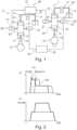
- Fig. 1 shows a schematic representation of an embodiment of an internal combustion engine 1 with a valve train 3.
- the valve train 3 is assigned several gas exchange valves, in the schematic representation two gas exchange valves 5, 5', which in turn are assigned to different combustion chambers 7, 7' of the internal combustion engine 1, which are also only shown schematically here.
- valve train 3 The operation of the valve train 3 will first be explained in connection with the first gas exchange valve 5.
- Identical and functionally equivalent elements assigned to the second gas exchange valve 5' are provided with corresponding, primed reference numerals, so that a separate explanation of these elements and their operation is not required. Instead, reference is made to the explanation of the elements provided with unprimed reference numerals.
- the interaction of the control of the various gas exchange valves 5, 5' in the valve train 3 will then be explained in more detail.
- the gas exchange valves 5, 5' are preferably designed as intake valves. However, it is also possible for them to be designed as exhaust valves, or for corresponding exhaust valves to be assigned to the valve train 1 in addition to the intake valves 5, 5'.
- the internal combustion engine 1 preferably has more than two combustion chambers 7, 7'. The number of combustion chambers 7, 7' is fundamentally unlimited.
- the internal combustion engine 1 can, in particular, have four, six, eight, ten, twelve, sixteen, eighteen, twenty, or twenty-four combustion chambers 7, 7'.
- the first gas exchange valve 5 is assigned a first, mechanically driven drive mechanism 9, which here has in particular a first piston 11 and a first piston rod 13, wherein the first piston rod 13 is operatively connected here to a cam 15 of a camshaft, by means of which the first piston rod 13 and thus at the same time the first piston 11 can be actuated in a stroke-movable manner.
- a second drive mechanism 17 is provided which is mechanically connected to the gas exchange valve 5 for the purpose of displacing it and which in particular has a second piston 19 and a second piston rod 21, and furthermore has a deflection mechanism 23 via which the second piston rod 21 is mechanically coupled to the gas exchange valve 5.
- the first drive mechanism 9 and the second drive mechanism 17 are operatively connected to one another via a hydraulic coupling device 25, wherein the hydraulic coupling device 25 has in particular a pressure chamber 27 which can be relieved of pressure via a valve device 29, wherein the pressure chamber 27 is designed to actuate the first drive mechanism 9 and the second Triemimik 17 to be coupled to one another under hydraulic pressure and to be decoupled from one another when the pressure is relieved.
- the two pistons 11, 19 are arranged together in the pressure chamber 27, so that when the pressure chamber 27 is under hydraulic pressure, the second piston 19 follows a lifting movement of the first piston 11 - mediated via the hydraulic medium - wherein the second piston 19 can be decoupled from the first piston 11 by relieving the pressure in the pressure chamber 27, so that the coupling via the hydraulic medium is canceled, wherein the second piston 19 can then no longer follow a lifting movement of the first piston 11.
- a variable lift for the gas exchange valve 5 can be achieved via the hydraulic coupling device 25, wherein, in particular, sub-curves can be obtained with reference to a valve lift curve defined by the shape of the cam 15.
- the valve train 3 is therefore designed as a variable valve train 3 and, in particular, as a fully variable valve train 3.
- the valve device 29 has at least two, here exactly two, switching valves 31, 33 which are fluidically connected to the pressure chamber 27 in parallel to one another, namely a first switching valve 31 and a second switching valve 33, wherein the pressure chamber 27 can be depressurized by at least one of the switching valves 31, 33 in the open state.
- the valve train 3 also has a control unit 35, of which only two output stages are schematically illustrated here, namely a first output stage 37 and a second output stage 39.
- the control unit 35 is configured to control, in particular to open, the switching valves 31, 33 with a time delay, but preferably with temporal overlap, to achieve a variable valve lift during a single stroke movement of the gas exchange valve 5.
- the switching valves 31, 33 as well as the switching valves 31', 33' of the second gas exchange valve 5' are of identical construction.
- the switching valves 31, 33, 31', 33' are preferably designed as high-speed valves, in particular as high-speed solenoid valves (HSSV).
- HSSV high-speed solenoid valves
- the control unit 35 is preferably configured to vary the time offset between the actuation of the switching valves 31, 33, 31', 33' assigned to the same valve device 29, 29'.
- the variation of the time offset can be carried out, in particular, depending on a current operating point of the internal combustion engine 1, most preferably depending on a characteristic map.
- a suitable valve lift curve and a separate, suitable switching behavior of the switching valves 31, 33, 31', 33' can be represented.
- Each of the switching valves 31, 33, 31', 33' is assigned an output stage 37, 39.
- the first switching valves 31, 31' are assigned the first output stage 37
- the second switching valves 33, 33' are assigned the second output stage 39.
- a common output stage 37, 39 is assigned to each of two switching valves 31, 31', 33, 33', which are assigned to different combustion chambers 7, 7', with the gas exchange cycles of the combustion chambers 7, 7' being separated from one another in time.
- their working cycles are phase-shifted relative to one another by half a working cycle period, i.e., in a four-stroke engine, by exactly 360° of the crankshaft angle.
- the two first switching valves 31, 31' which are assigned to the different gas exchange valves 5, 5', can be controlled by a common output stage, in this case the first output stage 37, with the two second switching valves 33, 33' also being controlled by another common output stage, in this case the second output stage 39, which is different from the first output stage 37.
- the switching valves 31, 33, 31', 33' of the same gas exchange valve 5, 5' are each controlled by different output stages 37, 39, so that a temporal offset in the control can be realized.
- two switching valves 31, 31', 33, 33' assigned to the different gas exchange valves 5, 5' share a common output stage 37, 39.
- the second cam 15' is in a position in which it does not cause any valve lift movement of the second gas exchange valve 5' via its first drive mechanism 9', so that the second gas exchange valve 5' - regardless of the switching behavior of the first switching valve 31' assigned to it - does not perform any lifting movement.
- the control of the first switching valve 31' assigned to the second gas exchange valve 5' in addition to the control of the first switching valve 31 assigned to the first gas exchange valve 5 by the first output stage 37 therefore has no additional effect, which is why it is possible to control the two first switching valves 31, 31' via the common first output stage 37.
- the output stages 37, 39 are activated with a time delay, so that the respective first switching valves 31, 31' and the respective second switching valves 33, 33' are activated with a time delay - but preferably with an overlapping time.
- Fig. 2 shows a diagrammatic representation of the operation of the valve train 3 according to Figure 1 .
- a diagrammatic plot - in schematic form - of a control current I against the crankshaft angle of the internal combustion engine 1 is shown.
- the solid, first curve K1 represents the control current I output by the first output stage 37 for the first switching valves 31, 31'
- second curve K2 represents the control current I of the second output stage 39 for the second switching valves 33, 33'.
- the first curve K1 and the second curve K2 are temporally overlap, but have a temporal offset ⁇ t from one another.
- This temporal offset ⁇ t is preferably variable, and it can be selected by the control unit 35, preferably depending on the operating point, in particular depending on the characteristic map.
- the time offset ⁇ t for the control of the switching valves 31, 33' can preferably be selected such that pressure pulsations arising due to the opening of the various switching valves 31, 33 interfere with each other.
- valve train 3 the internal combustion engine 1 and the method proposed here provide a very efficient and cost-effective way of realizing a fully variable valve train 3 with steep flanks while avoiding pressure pulsations.
Landscapes
- Engineering & Computer Science (AREA)
- Mechanical Engineering (AREA)
- General Engineering & Computer Science (AREA)
- Valve Device For Special Equipments (AREA)
Claims (9)
- Mécanisme (3) de commande de soupapes pour un moteur à combustion interne (1), comprenant- au moins une soupape (5, 5') d'échange de gaz ;- un premier mécanisme d'entraînement (9, 9') à entraînement mécanique ;- un deuxième mécanisme d'entraînement (17, 17') relié à ladite au moins une soupape (5, 5') d'échange de gaz pour déplacer celle-ci,- le premier mécanisme d'entraînement (9, 9') étant relié de manière fonctionnelle au deuxième mécanisme d'entraînement (17, 17') par un dispositif (25, 25') d'accouplement hydraulique,- le dispositif (25, 25') d'accouplement hydraulique comprenant une chambre de pression (27, 27') qui est apte à être mise sous pression par un dispositif de soupape (29, 29') et qui est conçue pour coupler entre eux le premier mécanisme d'entraînement (9, 9') et le deuxième mécanisme d'entraînement (17, 17') sous pression hydraulique et les découpler l'un de l'autre à l'état dépressurisé,- le dispositif de soupape (29, 29') présentant au moins deux soupapes de commutation (31, 33 ; 31', 33') reliées en parallèle, fluidiquement, à la chambre de pression (27, 27'), par l'intermédiaire desquelles la chambre de pression (27, 27') est apte à être mise sous pression par au moins une des soupapes de commutation (31, 33 ; 31', 33') lorsqu'elle est ouverte, caractérisé en ce que- le mécanisme (3) de commande de soupapes comprend un dispositif de commande (35) qui est conçu pour commander les soupapes de commutation (31, 33 ; 31', 33') de manière décalée dans le temps afin de représenter une course variable de ladite une soupape (5, 5') d'échange de gaz au cours d'un même mouvement de course de la soupape (5, 5') d'échange de gaz, et en ce que- à chacune des soupapes de commutation (31, 33 ; 31', 33') est associé un étage final (37, 39) conçu sous la forme d'un dispositif électronique pour la commande de la soupape de commutation respective (31, 33 ; 31', 33'), l'étage final (37, 39) étant conçu pour convertir un signal de commutation avec la puissance de commande nécessaire pour commuter la soupape de commutation respective (31, 33 ; 31', 33') et pour actionner la soupape de commutation (31, 33 ; 31', 33').
- Mécanisme (3) de commande de soupapes selon la revendication 1, caractérisé en ce que les soupapes de commutation (31, 33 ; 31', 33') du dispositif de soupape (29, 29') sont de construction identique.
- Mécanisme (3) de commande de soupapes selon l'une des revendications précédentes, caractérisé en ce que les soupapes de commutation (31, 33 ; 31', 33') sont conçues sous la forme de soupapes à grande vitesse.
- Mécanisme (3) de commande de soupapes selon l'une des revendications précédentes, caractérisé en ce que l'appareil de commande (35) est conçu de façon à faire varier le décalage temporel entre l'activation des soupapes de commutation (31, 33 ; 31', 33').
- Mécanisme (3) de commande de soupapes selon l'une des revendications précédentes, caractérisé en ce que le mécanisme (3) de commande de soupapes présente une pluralité de soupapes (5, 5') d'échange de gaz associées à différentes chambres de combustion (7, 7') d'un moteur à combustion interne (1), au moins deux soupapes de commande (31, 31' ; 33, 33'), qui sont associées aux différentes chambres de combustion (7, 7'), dont les cycles de changement de gaz sont séparés dans le temps, étant associées à un étage final commun (37, 39).
- Moteur à combustion interne (1), avec un mécanisme de soupapes (3) selon l'une des revendications 1 à 5.
- Moteur à combustion interne (1) selon la revendication 6, caractérisé en ce que le moteur à combustion interne (1) présente une pluralité de chambres de combustion (7, 7'), au moins une soupape (5, 5') d'échange de gaz ainsi qu'au moins un dispositif (25, 25') d'accouplement hydraulique du mécanisme (3) de commande de soupapes étant associés à chaque chambre de combustion (7, 7').
- Procédé de fonctionnement d'un moteur à combustion interne (1) avec un mécanisme (3) de commande de soupapes, en particulier selon l'une des revendications 1 à 5, caractérisé en ce que des soupapes de commande (31, 33 ; 31', 33'), reliées entre elles fluidiquement, de manière parallèle, par une même chambre de pression (27, 27') d'un dispositif (25, 25') d'accouplement hydraulique du mécanisme (3) de commande de soupapes, sont commandées de manière décalée les unes par rapport aux autres pendant un même mouvement de course d'une soupape (5, 5') d'échange de gaz associée au dispositif (25, 25') d'accouplement hydraulique, et en ce qu'un étage final (37, 39) conçu sous la forme d'un dispositif électronique pour la commande de la soupape de commutation respective (31, 33 ; 31', 33') est associé à chacune des soupapes de commutation (31, 33 ; 31', 33') pour la commande, l'étage de sortie (37, 39) étant conçu pour convertir un signal de commutation avec la puissance de commande nécessaire pour commuter la soupape de commutation respective (31, 33 ; 31', 33') et pour actionner la soupape de commutation (31, 33 ; 31', 33').
- Procédé selon la revendication 8, caractérisé en ce que le décalage temporel dans la commande des soupapes de commutation (31, 33 ; 31', 33') est modifié.
Applications Claiming Priority (2)
| Application Number | Priority Date | Filing Date | Title |
|---|---|---|---|
| DE102016224754.9A DE102016224754B4 (de) | 2016-12-12 | 2016-12-12 | Ventiltrieb für eine Brennkraftmaschine, Brennkraftmaschine mit einem solchen Ventiltrieb und Verfahren zum Betreiben einer Brennkraftmaschine mit einem solchen Ventiltrieb |
| PCT/EP2017/082150 WO2018108778A1 (fr) | 2016-12-12 | 2017-12-11 | Mécanisme de distribution pour un moteur à combustion interne, moteur à combustion interne comprenant un tel mécanisme de distribution et procédé permettant de faire fonctionner un moteur à combustion interne comprenant un tel mécanisme de distribution |
Publications (2)
| Publication Number | Publication Date |
|---|---|
| EP3551854A1 EP3551854A1 (fr) | 2019-10-16 |
| EP3551854B1 true EP3551854B1 (fr) | 2025-05-07 |
Family
ID=60972184
Family Applications (1)
| Application Number | Title | Priority Date | Filing Date |
|---|---|---|---|
| EP17829154.8A Active EP3551854B1 (fr) | 2016-12-12 | 2017-12-11 | Mécanisme de distribution pour un moteur à combustion interne, moteur à combustion interne comprenant un tel mécanisme de distribution et procédé permettant de faire fonctionner un moteur à combustion interne comprenant un tel mécanisme de distribution |
Country Status (5)
| Country | Link |
|---|---|
| US (1) | US11149597B2 (fr) |
| EP (1) | EP3551854B1 (fr) |
| CN (1) | CN110291276B (fr) |
| DE (1) | DE102016224754B4 (fr) |
| WO (1) | WO2018108778A1 (fr) |
Citations (3)
| Publication number | Priority date | Publication date | Assignee | Title |
|---|---|---|---|---|
| CN103925037A (zh) * | 2013-01-14 | 2014-07-16 | 浙江师范大学 | 一种新型可调液压挺柱 |
| EP2941547B1 (fr) * | 2013-01-07 | 2016-11-30 | Wärtsilä Finland Oy | Agencement de soulèvement de soupape et procédé d'actionnement de l'agencement de soulèvement de soupape |
| US9625050B2 (en) * | 2015-01-26 | 2017-04-18 | Ningbo Hoyea Machinery Manufacture Co., Ltd. | Engine valve actuation system |
Family Cites Families (8)
| Publication number | Priority date | Publication date | Assignee | Title |
|---|---|---|---|---|
| JPS5937222A (ja) | 1982-08-27 | 1984-02-29 | Mitsubishi Heavy Ind Ltd | エンジンの弁駆動装置 |
| JPS6095114A (ja) | 1983-10-31 | 1985-05-28 | Fujio Inoue | 原動機の弁開閉機構装置 |
| DE4132500A1 (de) | 1991-09-30 | 1993-04-01 | Bosch Gmbh Robert | Steuereinrichtung fuer gaswechselventile einer brennkraftmaschine |
| DE10020100A1 (de) | 2000-04-22 | 2001-10-31 | Dmc2 Degussa Metals Catalysts | Verfahren und Katalysator zur Reduktion von Stickoxiden |
| DE102006024669B4 (de) | 2006-05-26 | 2008-03-13 | Robert Bosch Gmbh | Anordnung zur Ansteuerung mehrerer Aktoren |
| US8474248B2 (en) | 2009-05-06 | 2013-07-02 | Detroit Diesel Corporation | Model based method for selective catalyst reducer urea dosing strategy |
| DE102013100632A1 (de) | 2013-01-22 | 2014-07-24 | Lsp Innovative Automotive Systems Gmbh | Variable elektrohydraulische Ventilsteuerung |
| DE102013220555B4 (de) | 2013-10-11 | 2015-05-13 | Schaeffler Technologies AG & Co. KG | Hydraulische Ventilsteuerung einer Brennkraftmaschine |
-
2016
- 2016-12-12 DE DE102016224754.9A patent/DE102016224754B4/de active Active
-
2017
- 2017-12-11 US US16/467,713 patent/US11149597B2/en active Active
- 2017-12-11 CN CN201780076773.XA patent/CN110291276B/zh active Active
- 2017-12-11 WO PCT/EP2017/082150 patent/WO2018108778A1/fr not_active Ceased
- 2017-12-11 EP EP17829154.8A patent/EP3551854B1/fr active Active
Patent Citations (3)
| Publication number | Priority date | Publication date | Assignee | Title |
|---|---|---|---|---|
| EP2941547B1 (fr) * | 2013-01-07 | 2016-11-30 | Wärtsilä Finland Oy | Agencement de soulèvement de soupape et procédé d'actionnement de l'agencement de soulèvement de soupape |
| CN103925037A (zh) * | 2013-01-14 | 2014-07-16 | 浙江师范大学 | 一种新型可调液压挺柱 |
| US9625050B2 (en) * | 2015-01-26 | 2017-04-18 | Ningbo Hoyea Machinery Manufacture Co., Ltd. | Engine valve actuation system |
Also Published As
| Publication number | Publication date |
|---|---|
| WO2018108778A1 (fr) | 2018-06-21 |
| DE102016224754B4 (de) | 2018-10-04 |
| EP3551854A1 (fr) | 2019-10-16 |
| CN110291276B (zh) | 2021-04-13 |
| DE102016224754A1 (de) | 2018-06-14 |
| US11149597B2 (en) | 2021-10-19 |
| CN110291276A (zh) | 2019-09-27 |
| US20190368391A1 (en) | 2019-12-05 |
Similar Documents
| Publication | Publication Date | Title |
|---|---|---|
| DE602005003110T2 (de) | Vorrichtung und Verfahren zur Kontrolle der Last und der Verbrennung in einer Brennkraftmaschine durch eine Ventilbetätigung mit mehrfachem Ventilhub pro Zyklus | |
| EP3033501B1 (fr) | Dispositif d'actionnement de soupape permettant de modifier la course de soupape | |
| EP2459849B1 (fr) | Dispositif de distribution à soupapes | |
| EP2118454B1 (fr) | dispositif de commande de soupape pour moteur à combustion interne à piston | |
| CH625016A5 (fr) | ||
| DE19544473A1 (de) | Mechanisch-hydraulisch arbeitende Steuerung für Gaswechselventile | |
| EP1649148B1 (fr) | Dispositif de commande pour une soupape, en particulier pour une soupape de renouvellement des gaz d'un moteur à combustion interne | |
| EP1760278A2 (fr) | Système de contrôle de course variable de soupape pour un moteur à combustion | |
| WO2013131602A1 (fr) | Dispositif de déphasage de distribution de moteur à combustion interne | |
| EP3551854B1 (fr) | Mécanisme de distribution pour un moteur à combustion interne, moteur à combustion interne comprenant un tel mécanisme de distribution et procédé permettant de faire fonctionner un moteur à combustion interne comprenant un tel mécanisme de distribution | |
| EP1840352B1 (fr) | Système d'alimentation d'air frais et méthode d'opération pour un moteur à piston | |
| EP2619422B1 (fr) | Moteur à combustion interne à quatre temps avec frein moteur | |
| DE102006045286A1 (de) | Dampfmaschine | |
| DE102008028697A1 (de) | Verfahren zur Ansteuerung eines elektromagnetischen Schaltventils | |
| DE102016200487A1 (de) | Brennkraftmaschine | |
| EP3440323B1 (fr) | Dispositif de commande variable de soupape d'admission et d'échappement et moteur comprenant un tel dispositif | |
| DE102016201499B4 (de) | Ventiltrieb für eine Brennkraftmaschine, Brennkraftmaschine mit einem solchen Ventiltrieb, und Verfahren zum Betreiben eines Ventiltriebs | |
| EP1812693B1 (fr) | Dispositif et procede pour reguler la levee d'une soupape d'echange gazeux d'echappement d'un moteur a combustion interne | |
| DE102006024669B4 (de) | Anordnung zur Ansteuerung mehrerer Aktoren | |
| DE102016113054A1 (de) | Brennkraftmaschine und Baukastensystem für einen Ventiltrieb einer Brennkraftmaschine | |
| DE102017131423B4 (de) | Brennkraftmaschine mit vier Zylindern und jeweils zwei Einlassventilen sowie Verfahren zum Betreiben einer solchen Brennkraftmaschine | |
| DE102008049166A1 (de) | Verbrennungskraftmaschine mit variabler Ventilsteuerung | |
| DE102007035305A1 (de) | Vorrichtung und Verfahren zur Ladungswechselsteuerung | |
| DE102005022888A1 (de) | Verfahren zum Betreiben einer Brennkraftmaschine mit zwei Zylinderbänken |
Legal Events
| Date | Code | Title | Description |
|---|---|---|---|
| STAA | Information on the status of an ep patent application or granted ep patent |
Free format text: STATUS: UNKNOWN |
|
| STAA | Information on the status of an ep patent application or granted ep patent |
Free format text: STATUS: THE INTERNATIONAL PUBLICATION HAS BEEN MADE |
|
| PUAI | Public reference made under article 153(3) epc to a published international application that has entered the european phase |
Free format text: ORIGINAL CODE: 0009012 |
|
| STAA | Information on the status of an ep patent application or granted ep patent |
Free format text: STATUS: REQUEST FOR EXAMINATION WAS MADE |
|
| 17P | Request for examination filed |
Effective date: 20190712 |
|
| AK | Designated contracting states |
Kind code of ref document: A1 Designated state(s): AL AT BE BG CH CY CZ DE DK EE ES FI FR GB GR HR HU IE IS IT LI LT LU LV MC MK MT NL NO PL PT RO RS SE SI SK SM TR |
|
| STAA | Information on the status of an ep patent application or granted ep patent |
Free format text: STATUS: EXAMINATION IS IN PROGRESS |
|
| 17Q | First examination report despatched |
Effective date: 20201006 |
|
| RAP3 | Party data changed (applicant data changed or rights of an application transferred) |
Owner name: ROLLS-ROYCE SOLUTIONS GMBH |
|
| P01 | Opt-out of the competence of the unified patent court (upc) registered |
Effective date: 20230530 |
|
| REG | Reference to a national code |
Ref country code: DE Ref legal event code: R079 Free format text: PREVIOUS MAIN CLASS: F01L0009020000 Ipc: F01L0009140000 Ref country code: DE Ref legal event code: R079 Ref document number: 502017016846 Country of ref document: DE Free format text: PREVIOUS MAIN CLASS: F01L0009020000 Ipc: F01L0009140000 |
|
| GRAP | Despatch of communication of intention to grant a patent |
Free format text: ORIGINAL CODE: EPIDOSNIGR1 |
|
| STAA | Information on the status of an ep patent application or granted ep patent |
Free format text: STATUS: GRANT OF PATENT IS INTENDED |
|
| RIC1 | Information provided on ipc code assigned before grant |
Ipc: F01L 9/14 20210101AFI20241113BHEP |
|
| INTG | Intention to grant announced |
Effective date: 20241202 |
|
| GRAS | Grant fee paid |
Free format text: ORIGINAL CODE: EPIDOSNIGR3 |
|
| GRAA | (expected) grant |
Free format text: ORIGINAL CODE: 0009210 |
|
| STAA | Information on the status of an ep patent application or granted ep patent |
Free format text: STATUS: THE PATENT HAS BEEN GRANTED |
|
| AK | Designated contracting states |
Kind code of ref document: B1 Designated state(s): AL AT BE BG CH CY CZ DE DK EE ES FI FR GB GR HR HU IE IS IT LI LT LU LV MC MK MT NL NO PL PT RO RS SE SI SK SM TR |
|
| REG | Reference to a national code |
Ref country code: GB Ref legal event code: FG4D Free format text: NOT ENGLISH |
|
| REG | Reference to a national code |
Ref country code: CH Ref legal event code: EP |
|
| REG | Reference to a national code |
Ref country code: DE Ref legal event code: R096 Ref document number: 502017016846 Country of ref document: DE |
|
| REG | Reference to a national code |
Ref country code: IE Ref legal event code: FG4D Free format text: LANGUAGE OF EP DOCUMENT: GERMAN |
|
| REG | Reference to a national code |
Ref country code: NL Ref legal event code: MP Effective date: 20250507 |
|
| PG25 | Lapsed in a contracting state [announced via postgrant information from national office to epo] |
Ref country code: FI Free format text: LAPSE BECAUSE OF FAILURE TO SUBMIT A TRANSLATION OF THE DESCRIPTION OR TO PAY THE FEE WITHIN THE PRESCRIBED TIME-LIMIT Effective date: 20250507 Ref country code: PT Free format text: LAPSE BECAUSE OF FAILURE TO SUBMIT A TRANSLATION OF THE DESCRIPTION OR TO PAY THE FEE WITHIN THE PRESCRIBED TIME-LIMIT Effective date: 20250908 Ref country code: ES Free format text: LAPSE BECAUSE OF FAILURE TO SUBMIT A TRANSLATION OF THE DESCRIPTION OR TO PAY THE FEE WITHIN THE PRESCRIBED TIME-LIMIT Effective date: 20250507 |
|
| REG | Reference to a national code |
Ref country code: LT Ref legal event code: MG9D |
|
| PG25 | Lapsed in a contracting state [announced via postgrant information from national office to epo] |
Ref country code: NO Free format text: LAPSE BECAUSE OF FAILURE TO SUBMIT A TRANSLATION OF THE DESCRIPTION OR TO PAY THE FEE WITHIN THE PRESCRIBED TIME-LIMIT Effective date: 20250807 Ref country code: GR Free format text: LAPSE BECAUSE OF FAILURE TO SUBMIT A TRANSLATION OF THE DESCRIPTION OR TO PAY THE FEE WITHIN THE PRESCRIBED TIME-LIMIT Effective date: 20250808 |
|
| PG25 | Lapsed in a contracting state [announced via postgrant information from national office to epo] |
Ref country code: NL Free format text: LAPSE BECAUSE OF FAILURE TO SUBMIT A TRANSLATION OF THE DESCRIPTION OR TO PAY THE FEE WITHIN THE PRESCRIBED TIME-LIMIT Effective date: 20250507 Ref country code: PL Free format text: LAPSE BECAUSE OF FAILURE TO SUBMIT A TRANSLATION OF THE DESCRIPTION OR TO PAY THE FEE WITHIN THE PRESCRIBED TIME-LIMIT Effective date: 20250507 |
|
| PG25 | Lapsed in a contracting state [announced via postgrant information from national office to epo] |
Ref country code: BG Free format text: LAPSE BECAUSE OF FAILURE TO SUBMIT A TRANSLATION OF THE DESCRIPTION OR TO PAY THE FEE WITHIN THE PRESCRIBED TIME-LIMIT Effective date: 20250507 |
|
| PG25 | Lapsed in a contracting state [announced via postgrant information from national office to epo] |
Ref country code: HR Free format text: LAPSE BECAUSE OF FAILURE TO SUBMIT A TRANSLATION OF THE DESCRIPTION OR TO PAY THE FEE WITHIN THE PRESCRIBED TIME-LIMIT Effective date: 20250507 |
|
| PG25 | Lapsed in a contracting state [announced via postgrant information from national office to epo] |
Ref country code: RS Free format text: LAPSE BECAUSE OF FAILURE TO SUBMIT A TRANSLATION OF THE DESCRIPTION OR TO PAY THE FEE WITHIN THE PRESCRIBED TIME-LIMIT Effective date: 20250807 |
|
| PG25 | Lapsed in a contracting state [announced via postgrant information from national office to epo] |
Ref country code: IS Free format text: LAPSE BECAUSE OF FAILURE TO SUBMIT A TRANSLATION OF THE DESCRIPTION OR TO PAY THE FEE WITHIN THE PRESCRIBED TIME-LIMIT Effective date: 20250907 |
|
| PG25 | Lapsed in a contracting state [announced via postgrant information from national office to epo] |
Ref country code: LV Free format text: LAPSE BECAUSE OF FAILURE TO SUBMIT A TRANSLATION OF THE DESCRIPTION OR TO PAY THE FEE WITHIN THE PRESCRIBED TIME-LIMIT Effective date: 20250507 |
|
| PGFP | Annual fee paid to national office [announced via postgrant information from national office to epo] |
Ref country code: DE Payment date: 20251211 Year of fee payment: 9 |
|
| PGFP | Annual fee paid to national office [announced via postgrant information from national office to epo] |
Ref country code: GB Payment date: 20251219 Year of fee payment: 9 |
|
| PG25 | Lapsed in a contracting state [announced via postgrant information from national office to epo] |
Ref country code: SM Free format text: LAPSE BECAUSE OF FAILURE TO SUBMIT A TRANSLATION OF THE DESCRIPTION OR TO PAY THE FEE WITHIN THE PRESCRIBED TIME-LIMIT Effective date: 20250507 Ref country code: DK Free format text: LAPSE BECAUSE OF FAILURE TO SUBMIT A TRANSLATION OF THE DESCRIPTION OR TO PAY THE FEE WITHIN THE PRESCRIBED TIME-LIMIT Effective date: 20250507 |
|
| PGFP | Annual fee paid to national office [announced via postgrant information from national office to epo] |
Ref country code: AT Payment date: 20251222 Year of fee payment: 9 |
|
| PGFP | Annual fee paid to national office [announced via postgrant information from national office to epo] |
Ref country code: IT Payment date: 20251223 Year of fee payment: 9 |
|
| PG25 | Lapsed in a contracting state [announced via postgrant information from national office to epo] |
Ref country code: CZ Free format text: LAPSE BECAUSE OF FAILURE TO SUBMIT A TRANSLATION OF THE DESCRIPTION OR TO PAY THE FEE WITHIN THE PRESCRIBED TIME-LIMIT Effective date: 20250507 |
|
| PG25 | Lapsed in a contracting state [announced via postgrant information from national office to epo] |
Ref country code: EE Free format text: LAPSE BECAUSE OF FAILURE TO SUBMIT A TRANSLATION OF THE DESCRIPTION OR TO PAY THE FEE WITHIN THE PRESCRIBED TIME-LIMIT Effective date: 20250507 |
|
| PG25 | Lapsed in a contracting state [announced via postgrant information from national office to epo] |
Ref country code: RO Free format text: LAPSE BECAUSE OF FAILURE TO SUBMIT A TRANSLATION OF THE DESCRIPTION OR TO PAY THE FEE WITHIN THE PRESCRIBED TIME-LIMIT Effective date: 20250507 Ref country code: SK Free format text: LAPSE BECAUSE OF FAILURE TO SUBMIT A TRANSLATION OF THE DESCRIPTION OR TO PAY THE FEE WITHIN THE PRESCRIBED TIME-LIMIT Effective date: 20250507 |