EP3551854B1 - Valve drive for an internal combustion engine, internal combustion engine comprising such a valve drive, and method for operating an internal combustion engine comprising such a valve drive - Google Patents
Valve drive for an internal combustion engine, internal combustion engine comprising such a valve drive, and method for operating an internal combustion engine comprising such a valve drive Download PDFInfo
- Publication number
- EP3551854B1 EP3551854B1 EP17829154.8A EP17829154A EP3551854B1 EP 3551854 B1 EP3551854 B1 EP 3551854B1 EP 17829154 A EP17829154 A EP 17829154A EP 3551854 B1 EP3551854 B1 EP 3551854B1
- Authority
- EP
- European Patent Office
- Prior art keywords
- valve
- internal combustion
- combustion engine
- gas exchange
- valves
- Prior art date
- Legal status (The legal status is an assumption and is not a legal conclusion. Google has not performed a legal analysis and makes no representation as to the accuracy of the status listed.)
- Active
Links
Images
Classifications
-
- F—MECHANICAL ENGINEERING; LIGHTING; HEATING; WEAPONS; BLASTING
- F01—MACHINES OR ENGINES IN GENERAL; ENGINE PLANTS IN GENERAL; STEAM ENGINES
- F01L—CYCLICALLY OPERATING VALVES FOR MACHINES OR ENGINES
- F01L9/00—Valve-gear or valve arrangements actuated non-mechanically
- F01L9/10—Valve-gear or valve arrangements actuated non-mechanically by fluid means, e.g. hydraulic
- F01L9/11—Valve-gear or valve arrangements actuated non-mechanically by fluid means, e.g. hydraulic in which the action of a cam is being transmitted to a valve by a liquid column
- F01L9/12—Valve-gear or valve arrangements actuated non-mechanically by fluid means, e.g. hydraulic in which the action of a cam is being transmitted to a valve by a liquid column with a liquid chamber between a piston actuated by a cam and a piston acting on a valve stem
- F01L9/14—Valve-gear or valve arrangements actuated non-mechanically by fluid means, e.g. hydraulic in which the action of a cam is being transmitted to a valve by a liquid column with a liquid chamber between a piston actuated by a cam and a piston acting on a valve stem the volume of the chamber being variable, e.g. for varying the lift or the timing of a valve
-
- F—MECHANICAL ENGINEERING; LIGHTING; HEATING; WEAPONS; BLASTING
- F01—MACHINES OR ENGINES IN GENERAL; ENGINE PLANTS IN GENERAL; STEAM ENGINES
- F01L—CYCLICALLY OPERATING VALVES FOR MACHINES OR ENGINES
- F01L1/00—Valve-gear or valve arrangements, e.g. lift-valve gear
- F01L1/02—Valve drive
- F01L1/04—Valve drive by means of cams, camshafts, cam discs, eccentrics or the like
- F01L1/047—Camshafts
-
- F—MECHANICAL ENGINEERING; LIGHTING; HEATING; WEAPONS; BLASTING
- F01—MACHINES OR ENGINES IN GENERAL; ENGINE PLANTS IN GENERAL; STEAM ENGINES
- F01L—CYCLICALLY OPERATING VALVES FOR MACHINES OR ENGINES
- F01L13/00—Modifications of valve-gear to facilitate reversing, braking, starting, changing compression ratio, or other specific operations
- F01L13/04—Modifications of valve-gear to facilitate reversing, braking, starting, changing compression ratio, or other specific operations for starting by means of fluid pressure
-
- F—MECHANICAL ENGINEERING; LIGHTING; HEATING; WEAPONS; BLASTING
- F01—MACHINES OR ENGINES IN GENERAL; ENGINE PLANTS IN GENERAL; STEAM ENGINES
- F01L—CYCLICALLY OPERATING VALVES FOR MACHINES OR ENGINES
- F01L13/00—Modifications of valve-gear to facilitate reversing, braking, starting, changing compression ratio, or other specific operations
- F01L2013/10—Auxiliary actuators for variable valve timing
- F01L2013/105—Hydraulic motors
-
- F—MECHANICAL ENGINEERING; LIGHTING; HEATING; WEAPONS; BLASTING
- F01—MACHINES OR ENGINES IN GENERAL; ENGINE PLANTS IN GENERAL; STEAM ENGINES
- F01L—CYCLICALLY OPERATING VALVES FOR MACHINES OR ENGINES
- F01L2201/00—Electronic control systems; Apparatus or methods therefor
-
- F—MECHANICAL ENGINEERING; LIGHTING; HEATING; WEAPONS; BLASTING
- F02—COMBUSTION ENGINES; HOT-GAS OR COMBUSTION-PRODUCT ENGINE PLANTS
- F02D—CONTROLLING COMBUSTION ENGINES
- F02D41/00—Electrical control of supply of combustible mixture or its constituents
- F02D41/0002—Controlling intake air
- F02D2041/001—Controlling intake air for engines with variable valve actuation
- F02D2041/0012—Controlling intake air for engines with variable valve actuation with selective deactivation of cylinders
Definitions
- the invention relates to a valve train for an internal combustion engine, an internal combustion engine with such a valve train, and a method for operating an internal combustion engine with such a valve train.
- a valve train of the type discussed here has at least one gas exchange valve and a first, mechanically driven drive mechanism, hereinafter referred to as the first drive mechanism.
- the valve train also has a second drive mechanism, hereinafter referred to as the second drive mechanism, which is connected to the at least one gas exchange valve for displacing it.
- the first drive mechanism is operatively connected to the second drive mechanism via a hydraulic coupling device, wherein the hydraulic coupling device has a pressure chamber that can be depressurized via a valve device.
- the coupling device is designed to couple the first drive mechanism and the second drive mechanism to one another under hydraulic pressure in the pressure chamber and to decouple them from one another when the pressure chamber is depressurized.
- a switching valve In order to be able to depressurize the pressure chamber, a switching valve is fluidically connected to it, via which switching valve the pressure chamber can be depressurized when the switching valve is open.
- the mechanically driven actuator typically specifies a valve lift curve which is only fully converted into a corresponding valve lift of the gas exchange valve if the pressure chamber is kept under hydraulic pressure throughout the entire course of the valve lift curve, wherein the coupling of the first actuator with the second actuator can be at least partially canceled by relieving pressure in the pressure chamber via the switching valve during the course of the valve lift curve, so that so-called sub-curves can be represented for the gas exchange valve, wherein, for example, in comparison to the predetermined valve lift curve, a later opening, a reduced stroke and/or an earlier closing of the gas exchange valve can be brought about.
- a disadvantage of this design is that the switching valve is difficult to adapt to the operation of an internal combustion engine. This particularly applies to the selection of a suitable size of the switching valve for a specific internal combustion engine. It turns out that in this respect, the product of a flow cross-section and a flow coefficient is particularly decisive for the behavior of the switching valve: If this product is too small, the hydraulic fluid is released slowly from the pressure chamber, resulting in flat flanks for the valve lift of the gas exchange valve, which in turn makes the valve react too sluggishly.
- the gas exchange valve can respond quickly to actuation of the switching valve, but this results in high pressure pulsations in the pressure chamber and ultimately in vibrations that make the behavior of the valve train uncontrollable and unpredictable. What makes things even more difficult is that a separate switching valve must be developed for each series, size and/or power class of an internal combustion engine, meaning that identical parts cannot be used in production for different internal combustion engines.
- a valve train which has at least two switching valves connected in parallel flow to one another by a pressure chamber, wherein the pressure chamber can be relieved of pressure via the opened switching valve in the open state of at least one of the switching valves.
- Hydraulically coupled valve trains are also known from DE 41 32 500 A1 , CN 103 925 037 B , US 2016/0215661 A1 and WO 85/01984 A1 known.
- the invention is based on the object of creating a valve train for an internal combustion engine, an internal combustion engine with such a valve train and a method for operating an internal combustion engine with such a valve train, wherein the aforementioned disadvantages do not occur.
- valve drive of the type mentioned above in that the valve device has at least two switching valves which are connected to the pressure chamber in parallel flow terms, via which the pressure chamber can be depressurised in the open state by at least one of the switching valves, wherein the valve train comprises a control unit configured to control the switching valves with a time offset relative to one another to achieve a variable valve lift of the at least one gas exchange valve during a stroke movement of the gas exchange valve.
- An additional advantage is that the switching valves are redundant, so the valve train remains functional even if one of the switching valves fails. While the valve train's full variability is no longer available, the remaining functionality is sufficient to operate the engine—in the sense of a limp home or emergency running function—until the next possible maintenance.
- the gas exchange valve can, in particular, be an intake valve or an exhaust valve associated with a combustion chamber of the internal combustion engine.
- the gas exchange valve is particularly preferably an intake valve.
- first drive mechanism is mechanically driven means, in particular, that it is not hydraulically driven.
- first mechanically driven drive mechanism has a direct mechanical drive connection to a valve drive, in particular to a camshaft.
- the first drive mechanism is therefore particularly preferably cam-driven.
- shape of an outer circumferential surface of a cam interacting with the first drive mechanism defines the valve lift curve, below which sub-curves can be displayed in the lift-time diagram of the gas exchange valve using the hydraulic coupling device.
- the first drive mechanism can also be referred to as the drive-side or cam-side drive mechanism because it is operatively connected to the valve drive.
- the second drive mechanism is preferably mechanically connected to the gas exchange valve for its displacement, particularly preferably purely mechanically, without any additional hydraulic or other non-mechanical couplings.
- the second drive mechanism can also be referred to as the gas exchange valve-side drive mechanism, since it is directly connected to the gas exchange valve and is therefore directly associated with it.
- the first drive mechanism preferably has a first piston that delimits the pressure chamber of the hydraulic coupling device on one side, as well as a first piston rod connected to the piston.
- a cam of the valve drive preferably interacts with the first piston rod of the first drive mechanism.
- a deflection mechanism it is also possible for a deflection mechanism to be connected between the cam and the first piston rod.
- the deflection mechanism is preferably designed mechanically.
- the second drive mechanism also preferably has a second piston closing off the pressure chamber of the hydraulic coupling device on another side facing away from the first piston of the first drive mechanism, as well as a second piston rod connected to the second piston rod, wherein the second piston rod of the second drive mechanism is connected to the gas exchange valve - preferably via a deflection mechanism, in particular a mechanical one.
- the control unit is configured, in particular, to actuate the switching valves with a time delay but overlapping during the stroke movement of the gas exchange valve.
- the control unit is configured to actuate the switching valves.
- the phrase "during a stroke movement of the gas exchange valve” means, in particular, that the switching valves are actuated, preferably opened, with a time delay but overlapping during the same stroke movement of the gas exchange valve.
- the switching valves of the valve device are of identical design. This results in particularly low logistical costs and low development effort, because a common parts strategy applies not only to an internal combustion engine, but also to different series, sizes and power classes of internal combustion engines, as already explained.
- the switching valves are designed as high-speed valves, in particular as so-called high-speed solenoid valves (HSSV).
- HSSV high-speed solenoid valves
- Such valves can be switched very quickly, having discrete switching positions, namely in particular a closed position and an open position.
- HSSV high-speed solenoid valves
- it is typically not possible to influence its switching speed. Rather, it can only be switched digitally.
- the temporal switching behavior of the valve device can nevertheless be influenced by controlling the various switching valves with a time offset but overlapping.
- control unit is configured to vary the time offset between the actuation of the switching valves. In particular, this makes it possible to influence the temporal behavior of the valve device and thus ultimately also the stroke movement of the gas exchange valve, even if the individual switching valves can only be controlled digitally.
- control unit is particularly configured to vary the time offset between the actuation of the switching valves assigned to the same valve device. The variation of the time offset is preferably dependent on the characteristic map. In this way, an optimal actuation of the valve device and thus also an optimal stroke movement of the gas exchange valve can be selected for each operating point of the internal combustion engine.
- each of the switching valves is assigned an output stage for control.
- the output stage provides the necessary power to activate and, in particular, open the switching valve(s) assigned to it.
- An output stage is understood, in particular, to be an electronic device for controlling a switching valve, which is configured, in particular, to convert a switching signal with the required control power to switch the switching valve and thus drive the switching valve.
- the valve train comprises a plurality of gas exchange valves assigned to different combustion chambers of an internal combustion engine.
- at least one hydraulic coupling device with a corresponding valve device is assigned to each combustion chamber.
- a common output stage is assigned to at least two, preferably exactly two, switching valves assigned to different combustion chambers, i.e., in particular, different hydraulic coupling devices, with the gas exchange cycles of the different combustion chambers being separated from one another in time.
- two switching valves are each controlled by a common output stage, which are assigned to different combustion chambers, wherein the gas exchange cycles of the combustion chambers are phase-shifted relative to one another by half a working cycle of the internal combustion engine, i.e. by 360° crankshaft angle in a four-stroke engine. If the output stage sends out a control signal, both switching valves assigned to the output stage are controlled.
- the object is also achieved by providing an internal combustion engine having a valve train according to one of the previously described embodiments.
- the advantages already explained in connection with the valve train are particularly evident.
- the time offset between the activation of the switching valves assigned to the same valve device can be varied depending on the characteristic map, the Pressure amplitudes and thus ultimately the valve lift of the gas exchange valves can be actively influenced over an entire characteristic map range of the internal combustion engine.
- the internal combustion engine has a plurality of combustion chambers, with each combustion chamber being assigned at least one gas exchange valve and at least one hydraulic coupling device of the valve train.
- each combustion chamber is assigned at least one intake valve and at least one exhaust valve, with each intake valve preferably being assigned a hydraulic coupling device of the valve train.
- each exhaust valve it is also possible for each exhaust valve to be assigned a hydraulic coupling device.
- the combustion chambers it is also possible for the combustion chambers to each have a plurality of intake valves and/or exhaust valves, in particular two intake valves and two exhaust valves.
- the internal combustion engine is preferably designed as a reciprocating piston engine. It is possible for the internal combustion engine to be configured to drive a passenger car, a truck, or a commercial vehicle. In a preferred embodiment, the internal combustion engine is used to drive, in particular, heavy land or water vehicles, for example, mining vehicles, trains (where the internal combustion engine is used in a locomotive or railcar), or ships. Use of the internal combustion engine to drive a defense vehicle, for example, a tank, is also possible.
- One embodiment of the internal combustion engine is preferably also used in a stationary application, for example, for stationary energy supply in emergency power operation, continuous load operation, or peak load operation, with the internal combustion engine preferably driving a generator in this case.
- the internal combustion engine can also be used in the industrial or construction sectors, for example, in a construction or building machine such as a crane or excavator.
- the internal combustion engine is preferably designed as a diesel engine, a gasoline engine, or a gas engine for operation with natural gas, biogas, special gas, or another suitable gas. Particularly when the internal combustion engine is designed as a gas engine, it is suitable for use in a combined heat and power plant for stationary energy generation.
- the object is finally also achieved by providing a method for operating an internal combustion engine with a valve train which has at least one gas exchange valve and a first, mechanically driven drive mechanism and a second drive mechanism connected to the at least one gas exchange valve, wherein the first drive mechanism is operatively connected to the second drive mechanism via a hydraulic coupling device, wherein the hydraulic coupling device has a pressure chamber which can be depressurized via a valve device and which is designed to couple the first drive mechanism and the second drive mechanism to one another under hydraulic pressure and to decouple them from one another in the depressurized state.
- the valve device has at least two switching valves which are fluidically connected to the pressure chamber in parallel to one another and via which the pressure chamber can be depressurized when at least one of the switching valves is in the open state.
- the switching valves for implementing a variable valve lift of at least one gas exchange valve are controlled, in particular opened, with a time offset from one another—but in particular with a temporal overlap—during a stroke movement of the gas exchange valve.
- a valve train according to one of the previously described exemplary embodiments is preferably used. In connection with the method, the advantages that have already been explained in connection with the valve train and the internal combustion engine arise, in particular.
- the time offset between the activation of the switching valves is varied - in particular depending on the operating point and particularly preferably depending on the characteristic map.
- valve train control unit is an engine control unit of the internal combustion engine, or that the functionality of the valve train control unit is integrated into a control unit, in particular the engine control unit of the internal combustion engine. However, it is also possible that a separate control unit is assigned to the valve train.
- the method proposed here can be permanently implemented in an electronic arrangement, in particular hardware, of the control unit.
- a computer program product to run on the control unit, which includes instructions on the basis of which the method described here can be carried out.
- a computer program product is also preferred, which has machine-readable instructions. on the basis of which a method according to one of the previously described embodiments is carried out when the computer program product runs on a computing device, in particular on a control device.
- a data carrier containing such a computer program product is also preferred.
- control device which has such a computer program product or on which such a computer program product runs.
- valve train and the internal combustion engine on the one hand and the method on the other hand are to be understood as complementary to one another.
- Method steps that have been described explicitly or implicitly in connection with the valve train and/or the internal combustion engine are preferably, individually or in combination with one another, steps of a preferred embodiment of the method.
- Features of the valve train and/or the internal combustion engine that have been explained in connection with the method are preferably, individually or in combination with one another, features of a preferred embodiment of the valve train and/or the internal combustion engine.
- the method is preferably characterized by at least one method step that is determined by at least one feature of an inventive or preferred embodiment of the valve train or the internal combustion engine.
- the internal combustion engine and/or the valve train are preferably characterized by at least one feature that is determined by at least one step of an inventive or preferred embodiment of the method.
- Fig. 1 shows a schematic representation of an embodiment of an internal combustion engine 1 with a valve train 3.
- the valve train 3 is assigned several gas exchange valves, in the schematic representation two gas exchange valves 5, 5', which in turn are assigned to different combustion chambers 7, 7' of the internal combustion engine 1, which are also only shown schematically here.
- valve train 3 The operation of the valve train 3 will first be explained in connection with the first gas exchange valve 5.
- Identical and functionally equivalent elements assigned to the second gas exchange valve 5' are provided with corresponding, primed reference numerals, so that a separate explanation of these elements and their operation is not required. Instead, reference is made to the explanation of the elements provided with unprimed reference numerals.
- the interaction of the control of the various gas exchange valves 5, 5' in the valve train 3 will then be explained in more detail.
- the gas exchange valves 5, 5' are preferably designed as intake valves. However, it is also possible for them to be designed as exhaust valves, or for corresponding exhaust valves to be assigned to the valve train 1 in addition to the intake valves 5, 5'.
- the internal combustion engine 1 preferably has more than two combustion chambers 7, 7'. The number of combustion chambers 7, 7' is fundamentally unlimited.
- the internal combustion engine 1 can, in particular, have four, six, eight, ten, twelve, sixteen, eighteen, twenty, or twenty-four combustion chambers 7, 7'.
- the first gas exchange valve 5 is assigned a first, mechanically driven drive mechanism 9, which here has in particular a first piston 11 and a first piston rod 13, wherein the first piston rod 13 is operatively connected here to a cam 15 of a camshaft, by means of which the first piston rod 13 and thus at the same time the first piston 11 can be actuated in a stroke-movable manner.
- a second drive mechanism 17 is provided which is mechanically connected to the gas exchange valve 5 for the purpose of displacing it and which in particular has a second piston 19 and a second piston rod 21, and furthermore has a deflection mechanism 23 via which the second piston rod 21 is mechanically coupled to the gas exchange valve 5.
- the first drive mechanism 9 and the second drive mechanism 17 are operatively connected to one another via a hydraulic coupling device 25, wherein the hydraulic coupling device 25 has in particular a pressure chamber 27 which can be relieved of pressure via a valve device 29, wherein the pressure chamber 27 is designed to actuate the first drive mechanism 9 and the second Triemimik 17 to be coupled to one another under hydraulic pressure and to be decoupled from one another when the pressure is relieved.
- the two pistons 11, 19 are arranged together in the pressure chamber 27, so that when the pressure chamber 27 is under hydraulic pressure, the second piston 19 follows a lifting movement of the first piston 11 - mediated via the hydraulic medium - wherein the second piston 19 can be decoupled from the first piston 11 by relieving the pressure in the pressure chamber 27, so that the coupling via the hydraulic medium is canceled, wherein the second piston 19 can then no longer follow a lifting movement of the first piston 11.
- a variable lift for the gas exchange valve 5 can be achieved via the hydraulic coupling device 25, wherein, in particular, sub-curves can be obtained with reference to a valve lift curve defined by the shape of the cam 15.
- the valve train 3 is therefore designed as a variable valve train 3 and, in particular, as a fully variable valve train 3.
- the valve device 29 has at least two, here exactly two, switching valves 31, 33 which are fluidically connected to the pressure chamber 27 in parallel to one another, namely a first switching valve 31 and a second switching valve 33, wherein the pressure chamber 27 can be depressurized by at least one of the switching valves 31, 33 in the open state.
- the valve train 3 also has a control unit 35, of which only two output stages are schematically illustrated here, namely a first output stage 37 and a second output stage 39.
- the control unit 35 is configured to control, in particular to open, the switching valves 31, 33 with a time delay, but preferably with temporal overlap, to achieve a variable valve lift during a single stroke movement of the gas exchange valve 5.
- the switching valves 31, 33 as well as the switching valves 31', 33' of the second gas exchange valve 5' are of identical construction.
- the switching valves 31, 33, 31', 33' are preferably designed as high-speed valves, in particular as high-speed solenoid valves (HSSV).
- HSSV high-speed solenoid valves
- the control unit 35 is preferably configured to vary the time offset between the actuation of the switching valves 31, 33, 31', 33' assigned to the same valve device 29, 29'.
- the variation of the time offset can be carried out, in particular, depending on a current operating point of the internal combustion engine 1, most preferably depending on a characteristic map.
- a suitable valve lift curve and a separate, suitable switching behavior of the switching valves 31, 33, 31', 33' can be represented.
- Each of the switching valves 31, 33, 31', 33' is assigned an output stage 37, 39.
- the first switching valves 31, 31' are assigned the first output stage 37
- the second switching valves 33, 33' are assigned the second output stage 39.
- a common output stage 37, 39 is assigned to each of two switching valves 31, 31', 33, 33', which are assigned to different combustion chambers 7, 7', with the gas exchange cycles of the combustion chambers 7, 7' being separated from one another in time.
- their working cycles are phase-shifted relative to one another by half a working cycle period, i.e., in a four-stroke engine, by exactly 360° of the crankshaft angle.
- the two first switching valves 31, 31' which are assigned to the different gas exchange valves 5, 5', can be controlled by a common output stage, in this case the first output stage 37, with the two second switching valves 33, 33' also being controlled by another common output stage, in this case the second output stage 39, which is different from the first output stage 37.
- the switching valves 31, 33, 31', 33' of the same gas exchange valve 5, 5' are each controlled by different output stages 37, 39, so that a temporal offset in the control can be realized.
- two switching valves 31, 31', 33, 33' assigned to the different gas exchange valves 5, 5' share a common output stage 37, 39.
- the second cam 15' is in a position in which it does not cause any valve lift movement of the second gas exchange valve 5' via its first drive mechanism 9', so that the second gas exchange valve 5' - regardless of the switching behavior of the first switching valve 31' assigned to it - does not perform any lifting movement.
- the control of the first switching valve 31' assigned to the second gas exchange valve 5' in addition to the control of the first switching valve 31 assigned to the first gas exchange valve 5 by the first output stage 37 therefore has no additional effect, which is why it is possible to control the two first switching valves 31, 31' via the common first output stage 37.
- the output stages 37, 39 are activated with a time delay, so that the respective first switching valves 31, 31' and the respective second switching valves 33, 33' are activated with a time delay - but preferably with an overlapping time.
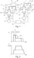
- Fig. 2 shows a diagrammatic representation of the operation of the valve train 3 according to Figure 1 .
- a diagrammatic plot - in schematic form - of a control current I against the crankshaft angle of the internal combustion engine 1 is shown.
- the solid, first curve K1 represents the control current I output by the first output stage 37 for the first switching valves 31, 31'
- second curve K2 represents the control current I of the second output stage 39 for the second switching valves 33, 33'.
- the first curve K1 and the second curve K2 are temporally overlap, but have a temporal offset ⁇ t from one another.
- This temporal offset ⁇ t is preferably variable, and it can be selected by the control unit 35, preferably depending on the operating point, in particular depending on the characteristic map.
- the time offset ⁇ t for the control of the switching valves 31, 33' can preferably be selected such that pressure pulsations arising due to the opening of the various switching valves 31, 33 interfere with each other.
- valve train 3 the internal combustion engine 1 and the method proposed here provide a very efficient and cost-effective way of realizing a fully variable valve train 3 with steep flanks while avoiding pressure pulsations.
Landscapes
- Engineering & Computer Science (AREA)
- Mechanical Engineering (AREA)
- General Engineering & Computer Science (AREA)
- Valve Device For Special Equipments (AREA)
Description
Die Erfindung betrifft einen Ventiltrieb für eine Brennkraftmaschine, eine Brennkraftmaschine mit einem solchen Ventiltrieb, und ein Verfahren zum Betreiben einer Brennkraftmaschine mit einem solchen Ventiltrieb.The invention relates to a valve train for an internal combustion engine, an internal combustion engine with such a valve train, and a method for operating an internal combustion engine with such a valve train.
Ein Ventiltrieb der hier angesprochenen Art weist wenigstens ein Gaswechselventil sowie einen ersten, mechanisch angetriebenen Triebmechanismus, im Folgenden als erste Triebmimik bezeichnet, auf. Weiterhin weist der Ventiltrieb einen zweiten, mit dem wenigstens einen Gaswechselventil zu dessen Verlagerung verbundenen Triebmechanismus, im Folgenden als zweite Triebmimik bezeichnet, auf. Die erste Triebmimik ist mit der zweiten Triebmimik über eine hydraulische Koppeleinrichtung wirkverbunden, wobei die hydraulische Koppeleinrichtung einen Druckraum aufweist, der über eine Ventileinrichtung druckentlastbar ist, wobei die Koppeleinrichtung eingerichtet ist, um die erste Triebmimik und die zweite Triebmimik unter Hydraulikdruck in dem Druckraum miteinander zu koppeln und im druckentlasteten Zustand des Druckraums voneinander zu entkoppeln. Um den Druckraum druckentlasten zu können, ist mit diesem strömungstechnisch ein Schaltventil verbunden, über welches der Druckraum im geöffneten Zustand des Schaltventils druckentlastbar ist. Somit ist es möglich, einen vollvariablen Ventiltrieb darzustellen. Dabei gibt die mechanisch angetriebene Triebmimik typischerweise eine Ventilhubkurve vor, die nur dann vollständig in einen entsprechenden Ventilhub des Gaswechselventils umgesetzt wird, wenn der Druckraum während des gesamten Verlaufs der Ventilhubkurve unter Hydraulikdruck gehalten wird, wobei die Kopplung der ersten Triebmimik mit der zweiten Triebmimik durch Druckentlasten des Druckraums über das Schaltventil während des Verlaufs der Ventilhubkurve zumindest teilweise aufgehoben werden kann, sodass für das Gaswechselventil sogenannte Unterkurven dargestellt werden können, wobei beispielsweise im Vergleich zu der vorgegebenen Ventilhubkurve insbesondere ein späteres Öffnen, ein verringerter Hubweg und/oder ein früheres Schließen des Gaswechselventils bewirkt werden kann/können.A valve train of the type discussed here has at least one gas exchange valve and a first, mechanically driven drive mechanism, hereinafter referred to as the first drive mechanism. The valve train also has a second drive mechanism, hereinafter referred to as the second drive mechanism, which is connected to the at least one gas exchange valve for displacing it. The first drive mechanism is operatively connected to the second drive mechanism via a hydraulic coupling device, wherein the hydraulic coupling device has a pressure chamber that can be depressurized via a valve device. The coupling device is designed to couple the first drive mechanism and the second drive mechanism to one another under hydraulic pressure in the pressure chamber and to decouple them from one another when the pressure chamber is depressurized. In order to be able to depressurize the pressure chamber, a switching valve is fluidically connected to it, via which switching valve the pressure chamber can be depressurized when the switching valve is open. This makes it possible to create a fully variable valve train. The mechanically driven actuator typically specifies a valve lift curve which is only fully converted into a corresponding valve lift of the gas exchange valve if the pressure chamber is kept under hydraulic pressure throughout the entire course of the valve lift curve, wherein the coupling of the first actuator with the second actuator can be at least partially canceled by relieving pressure in the pressure chamber via the switching valve during the course of the valve lift curve, so that so-called sub-curves can be represented for the gas exchange valve, wherein, for example, in comparison to the predetermined valve lift curve, a later opening, a reduced stroke and/or an earlier closing of the gas exchange valve can be brought about.
Nachteilig an dieser Ausgestaltung ist, dass das Schaltventil schwer auf den Betrieb einer Brennkraftmaschine abstimmbar ist. Dies betrifft insbesondere die Auswahl einer geeigneten Größe des Schaltventils für eine bestimmte Brennkraftmaschine. Dabei zeigt sich, dass insoweit insbesondere ein Produkt aus einem Strömungsquerschnitt und einem Durchflussbeiwert für das Verhalten des Schaltventils entscheidend ist: Ist dieses Produkt zu klein, erfolgt die Absteuerung von Hydraulikmittel aus dem Druckraum langsam, woraus flache Flanken für den Ventilhub des Gaswechselventils resultieren, wobei dieses mithin insbesondere zu träge reagiert. Ist das Produkt aus Strömungsquerschnitt und Durchflussbeiwert dagegen zu groß, kann zwar eine schnelle Reaktion des Gaswechselventils auf eine Ansteuerung des Schaltventils bewirkt werden, dafür kommt es aber zu hohen Druckpulsationen in dem Druckraum und letztlich zu Schwingungen, die das Verhalten des Ventiltriebs unkontrollierbar und unvorhersagbar machen. Es kommt erschwerend hinzu, dass für jede Baureihe, Baugröße und/oder Leistungsklasse einer Brennkraftmaschine ein eigenes Schaltventil entwickelt werden muss, sodass in der Produktion für verschiedene Brennkraftmaschinen keine Gleichteile verwendet werden können.A disadvantage of this design is that the switching valve is difficult to adapt to the operation of an internal combustion engine. This particularly applies to the selection of a suitable size of the switching valve for a specific internal combustion engine. It turns out that in this respect, the product of a flow cross-section and a flow coefficient is particularly decisive for the behavior of the switching valve: If this product is too small, the hydraulic fluid is released slowly from the pressure chamber, resulting in flat flanks for the valve lift of the gas exchange valve, which in turn makes the valve react too sluggishly. If, on the other hand, the product of flow cross-section and flow coefficient is too large, the gas exchange valve can respond quickly to actuation of the switching valve, but this results in high pressure pulsations in the pressure chamber and ultimately in vibrations that make the behavior of the valve train uncontrollable and unpredictable. What makes things even more difficult is that a separate switching valve must be developed for each series, size and/or power class of an internal combustion engine, meaning that identical parts cannot be used in production for different internal combustion engines.
Aus
Der Erfindung liegt die Aufgabe zugrunde, einen Ventiltrieb für eine Brennkraftmaschine, eine Brennkraftmaschine mit einem solchen Ventiltrieb und ein Verfahren zum Betreiben einer Brennkraftmaschine mit einem solchen Ventiltrieb zu schaffen, wobei die genannten Nachteile nicht auftreten.The invention is based on the object of creating a valve train for an internal combustion engine, an internal combustion engine with such a valve train and a method for operating an internal combustion engine with such a valve train, wherein the aforementioned disadvantages do not occur.
Die Aufgabe wird gelöst, indem die Gegenstände der unabhängigen Ansprüche geschaffen werden. Vorteilhafte Ausgestaltungen ergeben sich aus den Unteransprüchen.The problem is solved by creating the subject matter of the independent claims. Advantageous embodiments emerge from the subclaims.
Die Aufgabe wird insbesondere gelöst, indem ein Ventiltrieb der zuvor angesprochenen Art dadurch weitergebildet wird, dass die Ventileinrichtung mindestens zwei mit dem Druckraum strömungstechnisch parallel zueinander verbundene Schaltventile aufweist, über die der Druckraum in geöffnetem Zustand von wenigstens einem der Schaltventile druckentlastbar ist, wobei der Ventiltrieb ein Steuergerät aufweist, das eingerichtet ist, um die Schaltventile zur Darstellung eines variablen Ventilhubs des wenigstens einen Gaswechselventils während einer Hubbewegung des Gaswechselventils zeitversetzt zueinander anzusteuern. Hierdurch kann das Produkt aus Strömungsquerschnitt und Durchflussbeiwert im Vergleich zu nur einem Schaltventil vergrößert werden, wobei zugleich eine zeitlich gestufte Querschnittsfreigabe erfolgen kann, sodass Druckspitzen und damit letztlich auch Druckpulsationen sowie Druckschwingungen in dem Druckraum minimiert oder eliminiert werden können. Es ist daher möglich, zugleich einen großen Gesamtöffnungsquerschnitt - insbesondere bevorzugt größer als bei der Verwendung nur eines Schaltventils - bereitzustellen, und trotzdem Druckpulsationen im Druckraum sowie die damit verbundenen Nachteile zu vermeiden. Damit können steilere Flanken einer realen Hubkurve für das Gaswechselventil, insbesondere steilere Ventilschließflanken, erreicht werden, was insgesamt zu fülligeren Hubkurven führt.The object is achieved in particular by further developing a valve drive of the type mentioned above in that the valve device has at least two switching valves which are connected to the pressure chamber in parallel flow terms, via which the pressure chamber can be depressurised in the open state by at least one of the switching valves, wherein the valve train comprises a control unit configured to control the switching valves with a time offset relative to one another to achieve a variable valve lift of the at least one gas exchange valve during a stroke movement of the gas exchange valve. This allows the product of the flow cross-section and the flow coefficient to be increased compared to only one switching valve, while at the same time a time-graded cross-section release can take place, so that pressure peaks and thus ultimately also pressure pulsations and pressure oscillations in the pressure chamber can be minimized or eliminated. It is therefore It is possible to simultaneously provide a large overall opening cross-section—particularly preferably larger than when using only one switching valve—while still avoiding pressure pulsations in the pressure chamber and the associated disadvantages. This allows for steeper flanks of a real lift curve for the gas exchange valve, particularly steeper valve closing flanks, which leads to fuller lift curves overall.
Zudem wird eine Gleichteilstrategie für verschiedene Baureihen, Baugrößen und Leistungsklassen von Brennkraftmaschinen möglich, indem beispielsweise bei kleineren Brennkraftmaschinen - wie auch bisher üblich - nur ein Schaltventil verwendet wird, wobei für größere Brennkraftmaschinen zwei oder auch mehr Schaltventile verwendet werden können, wobei insbesondere für alle Brennkraftmaschinen die gleichen Schaltventile verwendet werden können. Dies führt zu einer vereinfachten Auslegung der verschiedenen Brennkraftmaschinen sowie zur Reduktion von Beschaffungs- und Logistikkosten in Zusammenhang mit den Schaltventilen.In addition, a common parts strategy for different series, sizes, and power classes of internal combustion engines becomes possible. For example, for smaller internal combustion engines, only one switching valve is used – as has been the case up to now – while for larger internal combustion engines, two or more switching valves can be used. In particular, the same switching valves can be used for all internal combustion engines. This leads to a simplified design of the various internal combustion engines and a reduction in procurement and logistics costs associated with the switching valves.
Als zusätzlicher Vorteil kommt hinzu, dass die Schaltventile redundant vorhanden sind, sodass der Ventiltrieb auch dann noch funktionsfähig ist, wenn eines der Schaltventile ausfällt. Es ist dann zwar nicht mehr die volle Variabilität des Ventiltriebs vorhanden, jedoch genügt die noch vorhandene Funktionalität jedenfalls, um die Brennkraftmaschine - im Sinne einer Limp Home- oder Notlauf-Funktion - bis zu einer nächstmöglichen Wartung zu betreiben.An additional advantage is that the switching valves are redundant, so the valve train remains functional even if one of the switching valves fails. While the valve train's full variability is no longer available, the remaining functionality is sufficient to operate the engine—in the sense of a limp home or emergency running function—until the next possible maintenance.
Bei dem Gaswechselventil kann es sich insbesondere um ein Einlassventil oder um ein Auslassventil handeln, welches einem Brennraum der Brennkraftmaschine zugeordnet ist. Besonders bevorzugt ist das Gaswechselventil ein Einlassventil.The gas exchange valve can, in particular, be an intake valve or an exhaust valve associated with a combustion chamber of the internal combustion engine. The gas exchange valve is particularly preferably an intake valve.
Dass die erste Triebmimik mechanisch angetrieben ist, bedeutet insbesondere, dass sie nicht hydraulisch angetrieben ist. Bevorzugt weist die erste mechanisch angetriebene Triebmimik eine direkte mechanische Antriebswirkverbindung zu einem Ventilantrieb auf, insbesondere zu einer Nockenwelle. Die erste Triebmimik ist also besonders bevorzugt nockengetrieben. Dabei definiert die Form einer äußeren Umfangsfläche eines mit der ersten Triebmimik zusammenwirkenden Nockens die Ventilhubkurve, unter der im Hubweg-Zeit-Diagramm des Gaswechselventils mittels der hydraulischen Koppeleinrichtung Unterkurven dargestellt werden können.The fact that the first drive mechanism is mechanically driven means, in particular, that it is not hydraulically driven. Preferably, the first mechanically driven drive mechanism has a direct mechanical drive connection to a valve drive, in particular to a camshaft. The first drive mechanism is therefore particularly preferably cam-driven. The shape of an outer circumferential surface of a cam interacting with the first drive mechanism defines the valve lift curve, below which sub-curves can be displayed in the lift-time diagram of the gas exchange valve using the hydraulic coupling device.
Die erste Triebmimik kann auch als antriebsseitige oder nockenseitige Triebmimik bezeichnet werden, weil sie mit dem Ventilantrieb wirkverbunden ist.The first drive mechanism can also be referred to as the drive-side or cam-side drive mechanism because it is operatively connected to the valve drive.
Die zweite Triebmimik ist vorzugsweise mechanisch mit dem Gaswechselventil zu dessen Verlagerung verbunden, besonders bevorzugt rein mechanisch, ohne weitere hydraulische oder anders geartete, nicht mechanische Kopplungen. Die zweite Triebmimik kann auch als gaswechselventilseitige Triebmimik bezeichnet werden, da sie mit dem Gaswechselventil direkt verbunden und insoweit diesem unmittelbar zugeordnet ist.The second drive mechanism is preferably mechanically connected to the gas exchange valve for its displacement, particularly preferably purely mechanically, without any additional hydraulic or other non-mechanical couplings. The second drive mechanism can also be referred to as the gas exchange valve-side drive mechanism, since it is directly connected to the gas exchange valve and is therefore directly associated with it.
Die erste Triebmimik weist vorzugsweise einen ersten Kolben auf, der den Druckraum der hydraulischen Koppeleinrichtung einseitig begrenzt, sowie eine mit dem Kolben verbundene erste Kolbenstange. Ein Nocken des Ventilantriebs wirkt vorzugsweise mit der ersten Kolbenstange der ersten Triebmimik zusammen. Es ist aber auch möglich, dass zwischen den Nocken und die erste Kolbenstange noch eine Umlenkmimik geschaltet ist. Die Umlenkmimik ist vorzugsweise mechanisch ausgestaltet.The first drive mechanism preferably has a first piston that delimits the pressure chamber of the hydraulic coupling device on one side, as well as a first piston rod connected to the piston. A cam of the valve drive preferably interacts with the first piston rod of the first drive mechanism. However, it is also possible for a deflection mechanism to be connected between the cam and the first piston rod. The deflection mechanism is preferably designed mechanically.
Auch die zweite Triebmimik weist vorzugsweise einen den Druckraum der hydraulischen Koppeleinrichtung auf einer anderen, dem ersten Kolben der ersten Triebmimik abgewandten Seite abschließenden zweiten Kolben sowie eine mit diesem verbundene zweite Kolbenstange auf, wobei die zweite Kolbenstange der zweiten Triebmimik - vorzugsweise über eine insbesondere mechanische Umlenkmimik - mit dem Gaswechselventil verbunden ist.The second drive mechanism also preferably has a second piston closing off the pressure chamber of the hydraulic coupling device on another side facing away from the first piston of the first drive mechanism, as well as a second piston rod connected to the second piston rod, wherein the second piston rod of the second drive mechanism is connected to the gas exchange valve - preferably via a deflection mechanism, in particular a mechanical one.
Das Steuergerät ist insbesondere eingerichtet, um die Schaltventile während der Hubbewegung des Gaswechselventils zeitversetzt, aber zeitlich überlappend anzusteuern. Insbesondere ist das Steuergerät eingerichtet, um die Schaltventile aufzusteuern. Die Formulierung "während einer Hubbewegung des Gaswechselventils" bedeutet insbesondere, dass die Schaltventile während einer selben Hubbewegung des Gaswechselventils zeitversetzt, aber zeitlich überlappend an-, vorzugsweise aufgesteuert werden.The control unit is configured, in particular, to actuate the switching valves with a time delay but overlapping during the stroke movement of the gas exchange valve. In particular, the control unit is configured to actuate the switching valves. The phrase "during a stroke movement of the gas exchange valve" means, in particular, that the switching valves are actuated, preferably opened, with a time delay but overlapping during the same stroke movement of the gas exchange valve.
Gemäß einer Weiterbildung der Erfindung ist vorgesehen, dass die Schaltventile der Ventileinrichtung baugleich ausgebildet sind. Insbesondere in diesem Fall ergeben sich besonders geringe logistische Kosten sowie ein geringer Entwicklungsaufwand, weil eine Gleichteilstrategie nicht nur bezüglich einer Brennkraftmaschine, sondern bezüglich verschiedener Baureihen, Baugrößen und Leistungsklassen von Brennkraftmaschinen verwendet werden kann, wie dies bereits erläutert wurde.According to a further development of the invention, the switching valves of the valve device are of identical design. This results in particularly low logistical costs and low development effort, because a common parts strategy applies not only to an internal combustion engine, but also to different series, sizes and power classes of internal combustion engines, as already explained.
Gemäß einer Weiterbildung der Erfindung ist vorgesehen, dass die Schaltventile als Hochgeschwindigkeitsventile, insbesondere als sogenannte High Speed Solenoid Valves (HSSV) ausgebildet sind. Solche Ventile können sehr schnell geschaltet werden, wobei sie diskrete Schaltpositionen besitzen, nämlich insbesondere eine Geschlossenstellung und eine Offenstellung. Dabei ist es bei der Ansteuerung eines solchen Hochgeschwindigkeitsschaltventils typischerweise nicht möglich, dessen Schaltgeschwindigkeit zu beeinflussen. Vielmehr kann dieses lediglich digital geschaltet werden. Bei dem hier vorgeschlagenen Ventiltrieb kann gleichwohl das zeitliche Schaltverhalten der Ventileinrichtung beeinflusst werden, indem die verschiedenen Schaltventile zeitlich versetzt, jedoch überlappend, angesteuert werden.According to a further development of the invention, the switching valves are designed as high-speed valves, in particular as so-called high-speed solenoid valves (HSSV). Such valves can be switched very quickly, having discrete switching positions, namely in particular a closed position and an open position. When controlling such a high-speed switching valve, it is typically not possible to influence its switching speed. Rather, it can only be switched digitally. With the valve train proposed here, the temporal switching behavior of the valve device can nevertheless be influenced by controlling the various switching valves with a time offset but overlapping.
Gemäß einer Weiterbildung der Erfindung ist vorgesehen, dass das Steuergerät eingerichtet ist, um den zeitlichen Versatz zwischen der Ansteuerung der Schaltventile zu variieren. Insbesondere auf diese Weise ist es möglich, das zeitliche Verhalten der Ventileinrichtung und damit letztlich auch die Hubbewegung des Gaswechselventils zu beeinflussen, auch wenn die einzelnen Schaltventile lediglich digital angesteuert werden können. Dabei ist das Steuergerät insbesondere eingerichtet, um den zeitlichen Versatz zwischen der Ansteuerung der einer selben Ventileinrichtung zugeordneten Schaltventile zu variieren. Die Variation des zeitlichen Versatzes erfolgt bevorzugt kennfeldabhängig. So kann für jeden Betriebspunkt der Brennkraftmaschine eine optimale Ansteuerung der Ventileinrichtung und damit auch eine optimale Hubbewegung des Gaswechselventils gewählt werden.According to a further development of the invention, the control unit is configured to vary the time offset between the actuation of the switching valves. In particular, this makes it possible to influence the temporal behavior of the valve device and thus ultimately also the stroke movement of the gas exchange valve, even if the individual switching valves can only be controlled digitally. In this case, the control unit is particularly configured to vary the time offset between the actuation of the switching valves assigned to the same valve device. The variation of the time offset is preferably dependent on the characteristic map. In this way, an optimal actuation of the valve device and thus also an optimal stroke movement of the gas exchange valve can be selected for each operating point of the internal combustion engine.
Erfindungsgemäß ist vorgesehen, dass jedem der Schaltventile eine Endstufe zur Ansteuerung zugeordnet ist. Die Endstufe stellt dabei die nötige Leistung bereit, um das ihr zugeordnete Schaltventil oder die ihr zugeordneten Schaltventile an- und insbesondere aufzusteuern. Unter einer Endstufe wird dabei insbesondere eine elektronische Einrichtung zur Ansteuerung eines Schaltventils verstanden, die insbesondere eingerichtet ist, um ein Schaltsignal mit der erforderlichen Ansteuerleistung zur Schaltung des Schaltventils umzusetzen und das Schaltventil damit zu treiben.According to the invention, each of the switching valves is assigned an output stage for control. The output stage provides the necessary power to activate and, in particular, open the switching valve(s) assigned to it. An output stage is understood, in particular, to be an electronic device for controlling a switching valve, which is configured, in particular, to convert a switching signal with the required control power to switch the switching valve and thus drive the switching valve.
Gemäß einer Weiterbildung der Erfindung ist vorgesehen, dass der Ventiltrieb eine Mehrzahl von Gaswechselventilen aufweist, die verschiedenen Brennräumen einer Brennkraftmaschine zugeordnet sind. Dabei ist vorzugsweise jedem Brennraum wenigstens eine hydraulische Koppeleinrichtung mit einer entsprechenden Ventileinrichtung zugeordnet. Es ist vorgesehen, dass jeweils wenigstens zwei, vorzugsweise genau zwei, Schaltventilen, die verschiedenen Brennräumen, das heißt insbesondere verschiedenen hydraulischen Koppeleinrichtungen, zugeordnet sind, wobei die Gaswechseltakte der verschiedenen Brennräume zeitlich voneinander getrennt sind, eine gemeinsame Endstufe zugeordnet ist. Auf diese Weise bedarf es keiner Vervielfältigung der Zahl der für den Ventiltrieb verwendeten Endstufen aufgrund der Vervielfältigung der Zahl der Schaltventile, da in geschickter Weise die Tatsache ausgenutzt wird, dass die Gaswechseltakte verschiedener Brennräume einer Brennkraftmaschine, die eine Mehrzahl von Brennräumen aufweist, zeitlich auseinanderfallen. Dies bedeutet insbesondere, dass die Gaswechseltakte solcher Brennräume miteinander nicht überlappen. Besonders bevorzugt werden jeweils zwei Schaltventile von einer gemeinsamen Endstufe angesteuert, die verschiedenen Brennräumen zugeordnet sind, wobei die Gaswechseltakte der Brennräume um ein halbes Arbeitsspiel der Brennkraftmaschine, bei einem Viertaktmotor also um 360° Kurbelwellenwinkel, relativ zueinander phasenverschoben sind. Sendet die Endstufe ein Ansteuersignal aus, werden beide der Endstufe zugeordneten Schaltventile angesteuert. Dies führt aber nur bei einem der den Schaltventilen zugeordneten Gaswechselventile tatsächlich zu einer Veränderung des Ventilhubs, da nur eines der Gaswechselventile über die ihm zugeordnete, erste Triebmimik tatsächlich zu einer Hubbewegung veranlasst wird, während das andere Gaswechselventil momentan inaktiv ist. Daher kann bei dem hier vorgeschlagenen Ventiltrieb mit der gleichen Zahl von Endstufen wie bei einem herkömmlichen Ventiltrieb insbesondere die doppelte Zahl an Schaltventilen angesteuert werden. Es entstehen insoweit in Verbindung mit dem hier vorgeschlagenen Ventiltrieb keine Mehrkosten.According to a further development of the invention, the valve train comprises a plurality of gas exchange valves assigned to different combustion chambers of an internal combustion engine. Preferably, at least one hydraulic coupling device with a corresponding valve device is assigned to each combustion chamber. A common output stage is assigned to at least two, preferably exactly two, switching valves assigned to different combustion chambers, i.e., in particular, different hydraulic coupling devices, with the gas exchange cycles of the different combustion chambers being separated from one another in time. This eliminates the need to multiply the number of output stages used for the valve train due to the multiplication of the number of switching valves, since the fact that the gas exchange cycles of different combustion chambers of an internal combustion engine having a plurality of combustion chambers differ in time is cleverly exploited. This means, in particular, that the gas exchange cycles of such combustion chambers do not overlap with one another. Particularly preferably, two switching valves are each controlled by a common output stage, which are assigned to different combustion chambers, wherein the gas exchange cycles of the combustion chambers are phase-shifted relative to one another by half a working cycle of the internal combustion engine, i.e. by 360° crankshaft angle in a four-stroke engine. If the output stage sends out a control signal, both switching valves assigned to the output stage are controlled. However, this only actually leads to a change in the valve lift of one of the gas exchange valves assigned to the switching valves, since only one of the gas exchange valves is actually caused to move in a stroke via the first drive mechanism assigned to it, while the other gas exchange valve is currently inactive. Therefore, with the valve train proposed here, with the same number of output stages as with a conventional valve train, in particular twice the number of switching valves can be controlled. In this respect, no additional costs arise in connection with the valve train proposed here.
Die Aufgabe wird auch gelöst, indem eine Brennkraftmaschine geschaffen wird, welche einen Ventiltrieb gemäß einem der zuvor beschriebenen Ausführungsbeispiele aufweist. In Zusammenhang mit der Brennkraftmaschine ergeben sich insbesondere die Vorteile, die bereits in Zusammenhang mit dem Ventiltrieb erläutert wurden.The object is also achieved by providing an internal combustion engine having a valve train according to one of the previously described embodiments. In connection with the internal combustion engine, the advantages already explained in connection with the valve train are particularly evident.
Insbesondere dann, wenn der zeitliche Versatz zwischen der Ansteuerung der einer selben Ventileinrichtung zugeordneten Schaltventile kennfeldabhängig variiert werden kann, sind die Druckamplituden und damit letztlich der Ventilhub der Gaswechselventile über einen gesamten Kennfeldbereich der Brennkraftmaschine aktiv beeinflussbar.In particular, if the time offset between the activation of the switching valves assigned to the same valve device can be varied depending on the characteristic map, the Pressure amplitudes and thus ultimately the valve lift of the gas exchange valves can be actively influenced over an entire characteristic map range of the internal combustion engine.
Gemäß einer Weiterbildung der Erfindung ist vorgesehen, dass die Brennkraftmaschine eine Mehrzahl von Brennräumen aufweist, wobei jedem Brennraum wenigstens ein Gaswechselventil sowie wenigstens eine hydraulische Koppeleinrichtung des Ventiltriebs zugeordnet ist. Bevorzugt ist jedem Brennraum wenigstens ein Einlassventil und wenigstens ein Auslassventil zugeordnet, wobei insbesondere bevorzugt jedem Einlassventil eine hydraulische Koppeleinrichtung des Ventiltriebs zugeordnet ist. Es ist aber alternativ oder zusätzlich auch möglich, dass den Auslassventilen jeweils eine hydraulische Koppeleinrichtung zugeordnet ist. Ebenso ist es möglich, dass die Brennräume jeweils eine Mehrzahl von Einlassventilen und/oder Auslassventilen, insbesondere zwei Einlassventile und zwei Auslassventile, aufweisen.According to a further development of the invention, the internal combustion engine has a plurality of combustion chambers, with each combustion chamber being assigned at least one gas exchange valve and at least one hydraulic coupling device of the valve train. Preferably, each combustion chamber is assigned at least one intake valve and at least one exhaust valve, with each intake valve preferably being assigned a hydraulic coupling device of the valve train. Alternatively or additionally, however, it is also possible for each exhaust valve to be assigned a hydraulic coupling device. It is also possible for the combustion chambers to each have a plurality of intake valves and/or exhaust valves, in particular two intake valves and two exhaust valves.
Die Brennkraftmaschine ist vorzugsweise als Hubkolbenmotor ausgebildet. Es ist möglich, dass die Brennkraftmaschine zum Antrieb eines Personenkraftwagens, eines Lastkraftwagens oder eines Nutzfahrzeugs eingerichtet ist. Bei einem bevorzugten Ausführungsbeispiel dient die Brennkraftmaschine dem Antrieb insbesondere schwerer Land- oder Wasserfahrzeuge, beispielsweise von Minenfahrzeugen, Zügen, wobei die Brennkraftmaschine in einer Lokomotive oder einem Triebwagen eingesetzt wird, oder von Schiffen. Auch ein Einsatz der Brennkraftmaschine zum Antrieb eines der Verteidigung dienenden Fahrzeugs, beispielsweise eines Panzers, ist möglich. Ein Ausführungsbeispiel der Brennkraftmaschine wird vorzugsweise auch stationär, beispielsweise zur stationären Energieversorgung im Notstrombetrieb, Dauerlastbetrieb oder Spitzenlastbetrieb eingesetzt, wobei die Brennkraftmaschine in diesem Fall vorzugsweise einen Generator antreibt. Auch eine stationäre Anwendung der Brennkraftmaschine zum Antrieb von Hilfsaggregaten, beispielsweise von Feuerlöschpumpen auf Bohrinseln, ist möglich. Weiterhin ist eine Anwendung der Brennkraftmaschine im Bereich der Förderung fossiler Roh- und insbesondere Brennstoffe, beispielswiese Öl und/oder Gas, möglich. Auch eine Verwendung der Brennkraftmaschine im industriellen Bereich oder im Konstruktionsbereich, beispielsweise in einer Konstruktions- oder Baumaschine, zum Beispiel in einem Kran oder einem Bagger, ist möglich. Die Brennkraftmaschine ist vorzugsweise als Dieselmotor, als Benzinmotor, als Gasmotor zum Betrieb mit Erdgas, Biogas, Sondergas oder einem anderen geeigneten Gas, ausgebildet. Insbesondere wenn die Brennkraftmaschine als Gasmotor ausgebildet ist, ist sie für den Einsatz in einem Blockheizkraftwerk zur stationären Energieerzeugung geeignet.The internal combustion engine is preferably designed as a reciprocating piston engine. It is possible for the internal combustion engine to be configured to drive a passenger car, a truck, or a commercial vehicle. In a preferred embodiment, the internal combustion engine is used to drive, in particular, heavy land or water vehicles, for example, mining vehicles, trains (where the internal combustion engine is used in a locomotive or railcar), or ships. Use of the internal combustion engine to drive a defense vehicle, for example, a tank, is also possible. One embodiment of the internal combustion engine is preferably also used in a stationary application, for example, for stationary energy supply in emergency power operation, continuous load operation, or peak load operation, with the internal combustion engine preferably driving a generator in this case. Stationary application of the internal combustion engine to drive auxiliary units, for example, fire pumps on drilling platforms, is also possible. Furthermore, application of the internal combustion engine in the field of extracting fossil raw materials and, in particular, fuels, for example, oil and/or gas, is possible. The internal combustion engine can also be used in the industrial or construction sectors, for example, in a construction or building machine such as a crane or excavator. The internal combustion engine is preferably designed as a diesel engine, a gasoline engine, or a gas engine for operation with natural gas, biogas, special gas, or another suitable gas. Particularly when the internal combustion engine is designed as a gas engine, it is suitable for use in a combined heat and power plant for stationary energy generation.
Die Aufgabe wird schließlich auch gelöst, indem ein Verfahren zum Betreiben einer Brennkraftmaschine mit einem Ventiltrieb geschaffen wird, der wenigstens ein Gaswechselventil sowie eine erste, mechanisch angetriebene Triebmimik und eine zweite, mit dem wenigstens einen Gaswechselventil verbundene Triebmimik aufweist, wobei die erste Triebmimik mit der zweiten Triebmimik über eine hydraulische Koppeleinrichtung wirkverbunden ist, wobei die hydraulische Koppeleinrichtung einen Druckraum aufweist, der über eine Ventileinrichtung druckentlastbar ist, und der eingerichtet ist, um die erste Triebmimik und die zweite Triebmimik unter Hydraulikdruck miteinander zu koppeln und in druckentlastetem Zustand voneinander zu entkoppeln. Dabei weist die Ventileinrichtung mindestens zwei mit dem Druckraum strömungstechnisch parallel zueinander verbundene Schaltventile auf, über die der Druckraum in geöffnetem Zustand von wenigstens einem der Schaltventile druckentlastbar ist. Im Rahmen des Verfahrens ist vorgesehen, dass die Schaltventile zur Darstellung eines variablen Ventilhubs des wenigstens eines Gaswechselventils während einer Hubbewegung des Gaswechselventils zeitversetzt - insbesondere jedoch zeitlich überlappend - zueinander angesteuert, insbesondere aufgesteuert werden. Im Rahmen des Verfahrens wird bevorzugt ein Ventiltrieb nach einem der zuvor beschriebenen Ausführungsbeispiele verwendet. In Zusammenhang mit dem Verfahren ergeben sich insbesondere die Vorteile, die bereits in Zusammenhang mit dem Ventiltrieb und der Brennkraftmaschine erläutert wurden.The object is finally also achieved by providing a method for operating an internal combustion engine with a valve train which has at least one gas exchange valve and a first, mechanically driven drive mechanism and a second drive mechanism connected to the at least one gas exchange valve, wherein the first drive mechanism is operatively connected to the second drive mechanism via a hydraulic coupling device, wherein the hydraulic coupling device has a pressure chamber which can be depressurized via a valve device and which is designed to couple the first drive mechanism and the second drive mechanism to one another under hydraulic pressure and to decouple them from one another in the depressurized state. The valve device has at least two switching valves which are fluidically connected to the pressure chamber in parallel to one another and via which the pressure chamber can be depressurized when at least one of the switching valves is in the open state. Within the scope of the method, it is provided that the switching valves for implementing a variable valve lift of at least one gas exchange valve are controlled, in particular opened, with a time offset from one another—but in particular with a temporal overlap—during a stroke movement of the gas exchange valve. Within the scope of the method, a valve train according to one of the previously described exemplary embodiments is preferably used. In connection with the method, the advantages that have already been explained in connection with the valve train and the internal combustion engine arise, in particular.
Gemäß einer Weiterbildung der Erfindung ist vorgesehen, dass der Zeitversatz zwischen der Ansteuerung der Schaltventile - insbesondere betriebspunktabhängig und besonders bevorzugt kennfeldabhängig - variiert wird.According to a further development of the invention, it is provided that the time offset between the activation of the switching valves is varied - in particular depending on the operating point and particularly preferably depending on the characteristic map.
Es ist möglich, dass das Steuergerät des Ventiltriebs ein Motorsteuergerät der Brennkraftmaschine ist, oder dass die Funktionalität des Steuergeräts des Ventiltriebs in ein Steuergerät, insbesondere in das Motorsteuergerät der Brennkraftmaschine integriert ist. Es ist aber auch möglich, dass dem Ventiltrieb ein separates Steuergerät zugeordnet ist.It is possible that the valve train control unit is an engine control unit of the internal combustion engine, or that the functionality of the valve train control unit is integrated into a control unit, in particular the engine control unit of the internal combustion engine. However, it is also possible that a separate control unit is assigned to the valve train.
Das hier vorgeschlagene Verfahren kann in eine elektronische Anordnung, insbesondere eine Hardware, des Steuergeräts fest implementiert sein. Es ist aber auch möglich, das auf dem Steuergerät ein Computerprogrammprodukt läuft, welches Anweisungen umfasst, aufgrund derer das hier beschriebene Verfahren durchführbar ist. Insofern wird auch ein Computerprogrammprodukt bevorzugt, welches maschinenlesbare Anweisungen aufweist, aufgrund derer ein Verfahren nach einer der zuvor beschriebenen Ausführungsformen durchgeführt wird, wenn das Computerprogrammprodukt auf einer Recheneinrichtung, insbesondere auf einem Steuergerät, läuft.The method proposed here can be permanently implemented in an electronic arrangement, in particular hardware, of the control unit. However, it is also possible for a computer program product to run on the control unit, which includes instructions on the basis of which the method described here can be carried out. In this respect, a computer program product is also preferred, which has machine-readable instructions. on the basis of which a method according to one of the previously described embodiments is carried out when the computer program product runs on a computing device, in particular on a control device.
Es wird auch ein Datenträger bevorzugt, der ein solches Computerprogrammprodukt aufweist.A data carrier containing such a computer program product is also preferred.
Weiterhin wird ein Steuergerät bevorzugt, welches ein solches Computerprogrammprodukt aufweist oder auf welchem ein solches Computerprogrammprodukt läuft.Furthermore, a control device is preferred which has such a computer program product or on which such a computer program product runs.
Die Beschreibung des Ventiltriebs sowie der Brennkraftmaschine einerseits und des Verfahrens andererseits sind komplementär zueinander zu verstehen. Verfahrensschritte, die explizit oder implizit in Zusammenhang mit dem Ventiltrieb und/oder der Brennkraftmaschine beschrieben wurden, sind bevorzugt einzeln oder miteinander kombiniert Schritte einer bevorzugten Ausführungsform des Verfahrens. Merkmale des Ventiltriebs und/oder der Brennkraftmaschine, die in Zusammenhang mit dem Verfahren erläutert wurden, sind bevorzugt einzeln oder miteinander kombiniert Merkmale eines bevorzugten Ausführungsbeispiels des Ventiltriebs und/oder der Brennkraftmaschine. Das Verfahren zeichnet sich bevorzugt durch wenigstens einen Verfahrensschritt aus, der durch wenigstens ein Merkmal eines erfindungsgemäßen oder bevorzugten Ausführungsbeispiels des Ventiltriebs oder der Brennkraftmaschine bedingt ist. Die Brennkraftmaschine und/oder der Ventiltrieb zeichnet/zeichnen sich bevorzugt durch wenigstens ein Merkmal aus, welches durch wenigstens einen Schritt einer erfindungsgemäßen oder bevorzugten Ausführungsform des Verfahrens bedingt ist.The description of the valve train and the internal combustion engine on the one hand and the method on the other hand are to be understood as complementary to one another. Method steps that have been described explicitly or implicitly in connection with the valve train and/or the internal combustion engine are preferably, individually or in combination with one another, steps of a preferred embodiment of the method. Features of the valve train and/or the internal combustion engine that have been explained in connection with the method are preferably, individually or in combination with one another, features of a preferred embodiment of the valve train and/or the internal combustion engine. The method is preferably characterized by at least one method step that is determined by at least one feature of an inventive or preferred embodiment of the valve train or the internal combustion engine. The internal combustion engine and/or the valve train are preferably characterized by at least one feature that is determined by at least one step of an inventive or preferred embodiment of the method.
Die Erfindung wird im Folgenden anhand der Zeichnung näher erläutert. Dabei zeigen:
Figur 1- eine schematische Darstellung eines Ausführungsbeispiels einer Brennkraftmaschine mit einem Ventiltrieb, und
- Figur 2
- eine schematische Darstellung der Funktionsweise des Ventiltriebs gemäß
Figur 1
- Figure 1
- a schematic representation of an embodiment of an internal combustion engine with a valve train, and
- Figure 2
- a schematic representation of the operation of the valve train according to
Figure 1 .
Die Funktionsweise des Ventiltriebs 3 wird zunächst in Zusammenhang mit dem ersten Gaswechselventil 5 erläutert. Dabei sind gleiche und funktionsgleiche Elemente, die dem zweiten Gaswechselventil 5' zugeordnet sind, mit jeweils entsprechenden, gestrichenen Bezugszeichen versehen, sodass es einer separaten Erläuterung dieser Elemente und deren Funktionsweise nicht bedarf; insofern wird vielmehr auf die Erläuterung zu den mit ungestrichenen Bezugszeichen versehenen Elementen verwiesen. Anschließend wird das Zusammenwirken der Ansteuerung der verschiedenen Gaswechselventile 5, 5' bei dem Ventiltrieb 3 näher erläutert.The operation of the
Die Gaswechselventile 5, 5' sind bevorzugt als Einlassventile ausgebildet. Es ist aber auch möglich, dass sie als Auslassventile ausgebildet sind, oder dass dem Ventiltrieb 1 zusätzlich zu den Einlassventilen 5, 5' entsprechende Auslassventile zugeordnet sind. Die Brennkraftmaschine 1 weist bevorzugt mehr als zwei Brennräume 7, 7' auf. Dabei ist die Anzahl der Brennräume 7, 7' grundsätzlich nicht begrenzt. Die Brennkraftmaschine 1 kann insbesondere vier, sechs, acht, zehn, zwölf, sechzehn, achtzehn, zwanzig oder vierundzwanzig Brennräume 7, 7' aufweisen.The
Dem ersten Gaswechselventil 5 ist eine erste, mechanisch angetriebene Triebmimik 9 zugeordnet, die hier insbesondere einen ersten Kolben 11 und eine erste Kolbenstange 13 aufweist, wobei die erste Kolbenstange 13 hier mit einem Nocken 15 einer Nockenwelle wirkverbunden ist, durch welchen die erste Kolbenstange 13 und damit zugleich der erste Kolben 11 hubbeweglich betätigbar ist.The first
Es ist außerdem eine zweite, mit dem Gaswechselventil 5 mechanisch zu dessen Verlagerung verbundene Triebmimik 17 vorgesehen, die insbesondere einen zweiten Kolben 19 und eine zweite Kolbenstange 21 aufweist, wobei sie weiter eine Umlenkmimik 23 aufweist, über welche die zweite Kolbenstange 21 mit dem Gaswechselventil 5 mechanisch gekoppelt ist.Furthermore, a
Die erste Triebmimik 9 und die zweite Triebmimik 17 sind über eine hydraulische Koppeleinrichtung 25 miteinander wirkverbunden, wobei die hydraulische Koppeleinrichtung 25 insbesondere einen Druckraum 27 aufweist, der über eine Ventileinrichtung 29 druckentlastbar ist, wobei der Druckraum 27 eingerichtet ist, um die erste Triebmimik 9 und die zweite Triemimik 17 unter Hydraulikdruck miteinander zu koppeln und im druckentlasteten Zustand voneinander zu entkoppeln. Hierzu sind die beiden Kolben 11, 19 gemeinsam in dem Druckraum 27 angeordnet, sodass der zweite Kolben 19 dann, wenn der Druckraum 27 unter Hydraulikdruck steht, einer Hubbewegung des ersten Kolbens 11 - vermittelt über das Hydraulikmittel - folgt, wobei der zweite Kolben 19 von dem ersten Kolben 11 entkoppelt werden kann, indem der Druckraum 27 druckentlastet wird, sodass die Kopplung über das Hydraulikmittel aufgehoben wird, wobei dann der zweite Kolben 19 einer Hubbewegung des ersten Kolbens 11 nicht mehr folgen kann.The
Entsprechend kann über die hydraulische Koppeleinrichtung 25 ein variabler Hub für das Gaswechselventil 5 dargestellt werden, wobei insbesondere Unterkurven mit Bezug auf eine durch die Form des Nockens 15 definierte Ventilhubkurve erhalten werden können. Der Ventiltrieb 3 ist daher als variabler Ventiltrieb 3 und insbesondere als vollvariabler Ventiltrieb 3 ausgebildet.Accordingly, a variable lift for the
Die Ventileinrichtung 29 weist mindestens zwei, hier genau zwei mit dem Druckraum 27 strömungstechnisch parallel zueinander verbundene Schaltventile 31, 33 auf, nämlich ein erstes Schaltventil 31 und ein zweites Schaltventil 33, wobei der Druckraum 27 in geöffnetem Zustand von wenigstens einem der Schaltventile 31, 33 druckentlastbar ist.The
Der Ventiltrieb 3 weist außerdem ein Steuergerät 35 auf, von dem hier schematisch nur zwei Endstufen, nämlich eine erste Endstufe 37 und eine zweite Endstufe 39, dargestellt sind. Das Steuergerät 35 ist eingerichtet, um die Schaltventile 31, 33 zur Darstellung eines variablen Ventilhubs während einer selben Hubbewegung des Gaswechselventils 5 zeitversetzt, jedoch bevorzugt zeitlich überlappend, anzusteuern, insbesondere aufzusteuern.The
Anstelle - wie von konventionellen Ventiltrieben bekannt - eines einzigen Schaltventils, über welches der Druckraum 27 druckentlastbar ist, sind diesem bei dem hier vorgeschlagenen Ventiltrieb 3 demnach mindestens die beiden Schaltventile 31, 33 zugeordnet, wodurch es möglich wird, zugleich einen vergleichsweise hohen Strömungsquerschnitt freizugeben und Druckpulsationen in dem Druckraum 27 zu minimieren, nämlich indem eine zeitlich gestufte Querschnittsfreigabe in Form der zeitversetzten Ansteuerung der Schaltventile 31, 33 durchgeführt wird. Somit können für das Gaswechselventil 5 steilere Ventilhubflanken, insbesondere steilere Ventilschließflanken, erreicht werden, wodurch sich insgesamt fülligere Hubkurven ergeben. Weiterhin ist eine Verwendung von Gleichteilen nicht nur an der Brennkraftmaschine 1, sondern auch bei einer gesamten Baureihe oder bei verschiedenen Baureihen, insbesondere verschiedenen Größen oder Leistungsklassen von Brennkraftmaschinen 1 möglich, weil das gleiche Schaltventil zur Bereitstellung größerer Strömungsquerschnitte vervielfältigt vorgesehen werden kann.Instead of a single switching valve, as is known from conventional valve trains, via which the
Insoweit ist insbesondere vorgesehen, dass die Schaltventile 31, 33 sowie auch die Schaltventile 31', 33' des zweiten Gaswechselventils 5' baugleich ausgebildet sind.In this respect, it is particularly provided that the switching
Die Schaltventile 31, 33, 31', 33' sind bevorzugt als Hochgeschwindigkeitsventile, insbesondere als High Speed Solenoid Valves (HSSV) ausgebildet.The switching
Das Steuergerät 35 ist bevorzugt eingerichtet, um den zeitlichen Versatz zwischen der Ansteuerung der einer selben Ventileinrichtung 29, 29' zugeordneten Schaltventile 31, 33, 31', 33' zu variieren, wobei die Variation des zeitlichen Versatzes insbesondere abhängig von einem momentanen Betriebspunkt der Brennkraftmaschine 1, ganz besonders bevorzugt kennfeldabhängig erfolgen kann. Somit kann für jeden Betriebspunkt der Brennkraftmaschine 1 eine geeignete Ventilhubkurve und ein eigenes, geeignetes Schaltverhalten der Schaltventile 31, 33, 31', 33', dargestellt werden.The
Jedem der Schaltventile 31, 33, 31', 33' ist eine Endstufe 37, 39 zugeordnet. Beispielsweise sind hier den ersten Schaltventilen 31, 31' die erste Endstufe 37 und den zweiten Schaltventilen 33, 33' die zweite Endstufe 39 zugeordnet.Each of the switching
Dabei zeigt sich, dass jeweils zwei Schaltventilen 31, 31', 33, 33', die verschiedenen Brennräumen 7, 7' zugeordnet sind, wobei die Gaswechseltakte der Brennräume 7, 7' zeitlich voneinander getrennt sind, eine gemeinsame Endstufe 37, 39 zugeordnet ist. Bei den hier dargestellten Brennräumen 7, 7' ist insoweit insbesondere vorgesehen, dass deren Arbeitsspiele relativ zueinander um eine halbe Arbeitsspiel-Periode phasenverschoben sind, bei einem Viertaktmotor also gerade um 360° Kurbelwellenwinkel. Daher können die beiden jeweils ersten Schaltventile 31, 31', die den verschiedenen Gaswechselventilen 5, 5' zugeordnet sind, von einer gemeinsamen Endstufe, hier nämlich der ersten Endstufe 37, angesteuert werden, wobei die beiden zweiten Schaltventile 33, 33' ebenfalls von einer anderen gemeinsamen Endstufe, hier nämlich von der zweiten Endstufe 39, die von der ersten Endstufe 37 verschieden ist, angesteuert werden können. Die Schaltventile 31, 33, 31', 33' des jeweils selben Gaswechselventils 5, 5' werden dabei von jeweils verschiedenen Endstufen 37, 39 angesteuert, sodass ein zeitlicher Versatz in der Ansteuerung verwirklicht werden kann. Dabei teilen sich aber je zwei den verschiedenen Gaswechselventilen 5, 5' zugeordnete Schaltventile 31, 31', 33, 33' eine gemeinsame Endstufe 37, 39.It can be seen that a
Sendet beispielsweise die erste Endstufe 37 ein Ansteuersignal aus, wird dies von den beiden ersten Schaltventilen 31, 31' empfangen, woraufhin diese aufgesteuert werden. Dies führt aber zu dem in
Das Gleiche gilt völlig analog für die zweite Endstufe 39 und die zweiten Schaltventile 33, 33'.The same applies analogously to the
Die Endstufen 37, 39 werden zeitversetzt aktiviert, sodass die jeweils ersten Schaltventile 31, 31' und die jeweils zweiten Schaltventile 33, 33' zeitversetzt - jedoch vorzugsweise zeitlich überlappend - aufgesteuert werden.The output stages 37, 39 are activated with a time delay, so that the respective
Bei b) ist das Produkt aus einem Strömungsquerschnitt A der Schaltventile 31, 33 mit einem Durchflussbeiwert Cd gegen den Kurbelwellenwinkel der Brennkraftmaschine 1 aufgetragen. Dabei zeigt sich, dass sich die Freigabe der Strömungsquerschnitte der einzelnen Schaltventile 31, 33 aufgrund von deren zeitversetzter Ansteuerung additiv verhält. Der Verlauf der Gesamtströmungsquerschnittsfreigabe für die beiden Schaltventile 31, 33, die zeitversetzt, jedoch überlappend zueinander aufgesteuert werden, verhält sich also gerade wie die Summe aus den jeweiligen Strömungsquerschnittfreigaben für die einzelnen Schaltventile 31, 33.In b), the product of a flow cross-section A of the switching
Somit ist es möglich, den Gesamtströmungsquerschnitt zeitlich gestuft freizugeben, und zugleich Druckpulsationen in dem Druckraum 27 zu minimieren, vorzugsweise zu verhindern.Thus, it is possible to release the total flow cross-section in stages over time and at the same time to minimize, preferably prevent, pressure pulsations in the
Dabei kann der zeitliche Versatz Δt für die Ansteuerung der Schaltventile 31, 33' bevorzugt so gewählt werden, dass sich entstehende Druckpulsationen aufgrund der Öffnung der verschiedenen Schaltventile 31, 33 weginterferieren.The time offset Δt for the control of the switching
Insgesamt zeigt sich, dass mit dem hier vorgeschlagenen Ventiltrieb 3, der Brennkraftmaschine 1 und dem Verfahren eine sehr effiziente und kostengünstige Möglichkeit geschaffen wird, einen vollvariablen Ventiltrieb 3 mit steilen Flanken unter Vermeidung von Druckpulsationen zu verwirklichen.Overall, it can be seen that the
Claims (9)
- Valve drive (3) for an internal combustion engine (1), having- at least one gas exchange valve (5, 5');- a first, mechanically driven drive mechanism (9,9');- a second drive mechanism (17, 17') that for repositioning the at least one gas exchange valve (5, 5') is connected to the latter, wherein- the first drive mechanism (9, 9') is operatively connected to the second drive mechanism (17, 17') by way of a hydraulic coupling installation (25, 25'), wherein- the hydraulic coupling installation (25, 25') has a pressure chamber (27, 27') which is capable of being relieved of pressure by way of a valve installation (29, 29') and which under hydraulic pressure is specified for coupling the first drive mechanism (9, 9') to the second drive mechanism (17, 17'), and in the pressure-relieved state is specified for decoupling the first drive mechanism from the second drive mechanism, wherein- the valve installation (29, 29') has at least two switch valves (31, 33; 31', 33') which are fluidically connected in parallel to the pressure chamber (27, 27') and by way of which the pressure chamber (27, 27') in the opened state is capable of being relieved of pressure by at least one of the switch valves (31, 33; 31', 33'), characterized in that- the valve drive (3) has a control apparatus (35) which, for representing a variable valve stroke of the at least one gas exchange valve (5, 5') during a same stroke movement of the gas exchange valve (5, 5'), is specified for actuating the switch valves (31, 33; 31', 33') in a temporally offset manner, and in that- each of the switch valves (31, 33; 31', 33') is assigned, for actuation, an end stage (37, 39) configured as an electronic installation for actuating the respective switch valve (31, 33; 31', 33'), wherein the end stage (37, 39) is specified for implementing a switching signal by way of the required actuating output for switching the respective switch valve (31, 33; 31', 33'), and for thus driving the switch valve (31, 33; 31', 33').
- Valve drive (3) according to Claim 1, characterized in that the switch valves (31, 33; 31', 33') of the valve installation (29, 29') are configured so as to be of identical construction.
- Valve drive (3) according to either of the preceding claims, characterized in that the switch valves (31, 33; 31', 33') are configured as high-speed valves.
- Valve drive (3) according to one of the preceding claims, characterized in that the control apparatus (35) is specified for varying the temporal offset between the actuation of the switch valves (31, 33; 31', 33').
- Valve drive (3) according to one of the preceding claims, characterized in that the valve drive (3) has a plurality of gas exchange valves (5, 5') that are assigned to different combustion chambers (7, 7') of an internal combustion engine (1), wherein a common end stage (37, 39) is in each case assigned to at least two switch valves (31, 31'; 33, 33') which are assigned to different combustion chambers (7, 7'), the gas exchange cycles of said different combustion chambers being temporally mutually separated.
- Internal combustion engine (1) having a valve drive (3) according to one of Claims 1 to 5.
- Internal combustion engine (1) according to Claim 6, characterized in that the internal combustion engine (1) has a plurality of combustion chambers (7, 7'), wherein each combustion chamber (7, 7') is assigned at least one gas exchange valve (5, 5') as well as at least one hydraulic coupling installation (25, 25') of the valve drive (3).
- Method for operating an internal combustion engine (1) having a valve drive (3), in particular according to one of Claims 1 to 5, characterized in that switch valves (31, 33; 31', 33') that are fluidically connected in parallel to a same pressure chamber (27, 27') of a hydraulic coupling installation (25, 25') of the valve drive (3) are actuated in a temporally mutually offset manner during a same stroke movement of a gas exchange valve (5, 5') that is assigned to the hydraulic coupling installation (25, 25'), and in that each of the switch valves (31, 33; 31', 33') is assigned, for actuation, an end stage (37, 39) configured as an electronic installation for actuating the respective switch valve (31, 33; 31', 33'), wherein the end stage (37, 39) is specified for implementing a switching signal by way of the required actuating output for switching the respective switch valve (31, 33; 31', 33'), and for thus driving the switch valve (31, 33; 31', 33').
- Method according to Claim 8, characterized in that the temporal offset in the actuation of the switch valves (31, 33; 31', 33') is varied.
Applications Claiming Priority (2)
| Application Number | Priority Date | Filing Date | Title |
|---|---|---|---|
| DE102016224754.9A DE102016224754B4 (en) | 2016-12-12 | 2016-12-12 | Valve train for an internal combustion engine, internal combustion engine with such a valve train and method for operating an internal combustion engine with such a valve train |
| PCT/EP2017/082150 WO2018108778A1 (en) | 2016-12-12 | 2017-12-11 | Valve drive for an internal combustion engine, internal combustion engine comprising such a valve drive, and method for operating an internal combustion engine comprising such a valve drive |
Publications (2)
| Publication Number | Publication Date |
|---|---|
| EP3551854A1 EP3551854A1 (en) | 2019-10-16 |
| EP3551854B1 true EP3551854B1 (en) | 2025-05-07 |
Family
ID=60972184
Family Applications (1)
| Application Number | Title | Priority Date | Filing Date |
|---|---|---|---|
| EP17829154.8A Active EP3551854B1 (en) | 2016-12-12 | 2017-12-11 | Valve drive for an internal combustion engine, internal combustion engine comprising such a valve drive, and method for operating an internal combustion engine comprising such a valve drive |
Country Status (5)
| Country | Link |
|---|---|
| US (1) | US11149597B2 (en) |
| EP (1) | EP3551854B1 (en) |
| CN (1) | CN110291276B (en) |
| DE (1) | DE102016224754B4 (en) |
| WO (1) | WO2018108778A1 (en) |
Citations (3)
| Publication number | Priority date | Publication date | Assignee | Title |
|---|---|---|---|---|
| CN103925037A (en) * | 2013-01-14 | 2014-07-16 | 浙江师范大学 | Novel adjustable hydraulic tappet |
| EP2941547B1 (en) * | 2013-01-07 | 2016-11-30 | Wärtsilä Finland Oy | Valve lifting arrangement and method for operating valve lifting arrangement |
| US9625050B2 (en) * | 2015-01-26 | 2017-04-18 | Ningbo Hoyea Machinery Manufacture Co., Ltd. | Engine valve actuation system |
Family Cites Families (8)
| Publication number | Priority date | Publication date | Assignee | Title |
|---|---|---|---|---|
| JPS5937222A (en) | 1982-08-27 | 1984-02-29 | Mitsubishi Heavy Ind Ltd | Valve gear of engine |
| JPS6095114A (en) | 1983-10-31 | 1985-05-28 | Fujio Inoue | Valve switching mechanism of motor |
| DE4132500A1 (en) | 1991-09-30 | 1993-04-01 | Bosch Gmbh Robert | Cylinder-head valve with variable timing for IC engine - has sprung coupling to camshaft with hydraulic system with control valves to shorten cylinder valve timing. |
| DE10020100A1 (en) | 2000-04-22 | 2001-10-31 | Dmc2 Degussa Metals Catalysts | Process and catalyst for the reduction of nitrogen oxides |
| DE102006024669B4 (en) | 2006-05-26 | 2008-03-13 | Robert Bosch Gmbh | Arrangement for controlling a plurality of actuators |
| US8474248B2 (en) | 2009-05-06 | 2013-07-02 | Detroit Diesel Corporation | Model based method for selective catalyst reducer urea dosing strategy |
| DE102013100632A1 (en) | 2013-01-22 | 2014-07-24 | Lsp Innovative Automotive Systems Gmbh | Variable electrohydraulic valve control |
| DE102013220555B4 (en) | 2013-10-11 | 2015-05-13 | Schaeffler Technologies AG & Co. KG | Hydraulic valve control of an internal combustion engine |
-
2016
- 2016-12-12 DE DE102016224754.9A patent/DE102016224754B4/en active Active
-
2017
- 2017-12-11 US US16/467,713 patent/US11149597B2/en active Active
- 2017-12-11 CN CN201780076773.XA patent/CN110291276B/en active Active
- 2017-12-11 WO PCT/EP2017/082150 patent/WO2018108778A1/en not_active Ceased
- 2017-12-11 EP EP17829154.8A patent/EP3551854B1/en active Active
Patent Citations (3)
| Publication number | Priority date | Publication date | Assignee | Title |
|---|---|---|---|---|
| EP2941547B1 (en) * | 2013-01-07 | 2016-11-30 | Wärtsilä Finland Oy | Valve lifting arrangement and method for operating valve lifting arrangement |
| CN103925037A (en) * | 2013-01-14 | 2014-07-16 | 浙江师范大学 | Novel adjustable hydraulic tappet |
| US9625050B2 (en) * | 2015-01-26 | 2017-04-18 | Ningbo Hoyea Machinery Manufacture Co., Ltd. | Engine valve actuation system |
Also Published As
| Publication number | Publication date |
|---|---|
| WO2018108778A1 (en) | 2018-06-21 |
| DE102016224754B4 (en) | 2018-10-04 |
| EP3551854A1 (en) | 2019-10-16 |
| CN110291276B (en) | 2021-04-13 |
| DE102016224754A1 (en) | 2018-06-14 |
| US11149597B2 (en) | 2021-10-19 |
| CN110291276A (en) | 2019-09-27 |
| US20190368391A1 (en) | 2019-12-05 |
Similar Documents
| Publication | Publication Date | Title |
|---|---|---|
| DE602005003110T2 (en) | Apparatus and method for controlling load and combustion in an internal combustion engine by valve actuation with multiple valve lift per cycle | |
| EP3033501B1 (en) | Valve-actuating device for changing the valve stroke | |
| EP2459849B1 (en) | Valve train device | |
| EP2118454B1 (en) | Valve drive in a reciprocating piston combustion engine | |
| CH625016A5 (en) | ||
| DE19544473A1 (en) | Mechanically-hydraulically operating control for gas change valves of internal combustion engines | |
| EP1649148B1 (en) | Control device for a valve, particularly a gas exchange valve of an internal combustion engine | |
| EP1760278A2 (en) | Lift-variable valve-operating system for internal combustion engine | |
| WO2013131602A1 (en) | Internal combustion engine valve train adjustment device | |
| EP3551854B1 (en) | Valve drive for an internal combustion engine, internal combustion engine comprising such a valve drive, and method for operating an internal combustion engine comprising such a valve drive | |
| EP1840352B1 (en) | Air intake system and method of operating for a piston engine | |
| EP2619422B1 (en) | Four strokes internal combustion engine with an engine brake | |
| DE102006045286A1 (en) | steam engine | |
| DE102008028697A1 (en) | Method for controlling an electromagnetic switching valve | |
| DE102016200487A1 (en) | Internal combustion engine | |
| EP3440323B1 (en) | Variable valve drive arrangement for an inlet and an outlet valve, and engine with such a drive | |
| DE102016201499B4 (en) | Valve drive for an internal combustion engine, internal combustion engine with such a valve drive, and method for operating a valve drive | |
| EP1812693B1 (en) | Device and method for controlling the lift of an outlet gas exchange valve of an internal combustion engine | |
| DE102006024669B4 (en) | Arrangement for controlling a plurality of actuators | |
| DE102016113054A1 (en) | Internal combustion engine and modular system for a valve train of an internal combustion engine | |
| DE102017131423B4 (en) | Internal combustion engine with four cylinders and two inlet valves each and method for operating such an internal combustion engine | |
| DE102008049166A1 (en) | Internal combustion engine i.e. four-cylinder internal combustion engine, has gas exchange valves for converting rotation of drive into oscillating rotary motion of output shaft around variably adjustable rotating angle | |
| DE102007035305A1 (en) | Gas exchange controlling device for internal-combustion engine, has inlet cross section controlled by inlet valve larger than another inlet cross section controlled by another inlet valve | |
| DE102005022888A1 (en) | Operating process for internal combustion engine involves opening inlet valves of cylinders of one bank only slightly, or less than inlet valves of cylinders of other bank |
Legal Events
| Date | Code | Title | Description |
|---|---|---|---|
| STAA | Information on the status of an ep patent application or granted ep patent |
Free format text: STATUS: UNKNOWN |
|
| STAA | Information on the status of an ep patent application or granted ep patent |
Free format text: STATUS: THE INTERNATIONAL PUBLICATION HAS BEEN MADE |
|
| PUAI | Public reference made under article 153(3) epc to a published international application that has entered the european phase |
Free format text: ORIGINAL CODE: 0009012 |
|
| STAA | Information on the status of an ep patent application or granted ep patent |
Free format text: STATUS: REQUEST FOR EXAMINATION WAS MADE |
|
| 17P | Request for examination filed |
Effective date: 20190712 |
|
| AK | Designated contracting states |
Kind code of ref document: A1 Designated state(s): AL AT BE BG CH CY CZ DE DK EE ES FI FR GB GR HR HU IE IS IT LI LT LU LV MC MK MT NL NO PL PT RO RS SE SI SK SM TR |
|
| STAA | Information on the status of an ep patent application or granted ep patent |
Free format text: STATUS: EXAMINATION IS IN PROGRESS |
|
| 17Q | First examination report despatched |
Effective date: 20201006 |
|
| RAP3 | Party data changed (applicant data changed or rights of an application transferred) |
Owner name: ROLLS-ROYCE SOLUTIONS GMBH |
|
| P01 | Opt-out of the competence of the unified patent court (upc) registered |
Effective date: 20230530 |
|
| REG | Reference to a national code |
Ref country code: DE Ref legal event code: R079 Free format text: PREVIOUS MAIN CLASS: F01L0009020000 Ipc: F01L0009140000 Ref country code: DE Ref legal event code: R079 Ref document number: 502017016846 Country of ref document: DE Free format text: PREVIOUS MAIN CLASS: F01L0009020000 Ipc: F01L0009140000 |
|
| GRAP | Despatch of communication of intention to grant a patent |
Free format text: ORIGINAL CODE: EPIDOSNIGR1 |
|
| STAA | Information on the status of an ep patent application or granted ep patent |
Free format text: STATUS: GRANT OF PATENT IS INTENDED |
|
| RIC1 | Information provided on ipc code assigned before grant |
Ipc: F01L 9/14 20210101AFI20241113BHEP |
|
| INTG | Intention to grant announced |
Effective date: 20241202 |
|
| GRAS | Grant fee paid |
Free format text: ORIGINAL CODE: EPIDOSNIGR3 |
|
| GRAA | (expected) grant |
Free format text: ORIGINAL CODE: 0009210 |
|
| STAA | Information on the status of an ep patent application or granted ep patent |
Free format text: STATUS: THE PATENT HAS BEEN GRANTED |
|
| AK | Designated contracting states |
Kind code of ref document: B1 Designated state(s): AL AT BE BG CH CY CZ DE DK EE ES FI FR GB GR HR HU IE IS IT LI LT LU LV MC MK MT NL NO PL PT RO RS SE SI SK SM TR |
|
| REG | Reference to a national code |
Ref country code: GB Ref legal event code: FG4D Free format text: NOT ENGLISH |
|
| REG | Reference to a national code |
Ref country code: CH Ref legal event code: EP |
|
| REG | Reference to a national code |
Ref country code: DE Ref legal event code: R096 Ref document number: 502017016846 Country of ref document: DE |
|
| REG | Reference to a national code |
Ref country code: IE Ref legal event code: FG4D Free format text: LANGUAGE OF EP DOCUMENT: GERMAN |
|
| REG | Reference to a national code |
Ref country code: NL Ref legal event code: MP Effective date: 20250507 |
|
| PG25 | Lapsed in a contracting state [announced via postgrant information from national office to epo] |
Ref country code: FI Free format text: LAPSE BECAUSE OF FAILURE TO SUBMIT A TRANSLATION OF THE DESCRIPTION OR TO PAY THE FEE WITHIN THE PRESCRIBED TIME-LIMIT Effective date: 20250507 Ref country code: PT Free format text: LAPSE BECAUSE OF FAILURE TO SUBMIT A TRANSLATION OF THE DESCRIPTION OR TO PAY THE FEE WITHIN THE PRESCRIBED TIME-LIMIT Effective date: 20250908 Ref country code: ES Free format text: LAPSE BECAUSE OF FAILURE TO SUBMIT A TRANSLATION OF THE DESCRIPTION OR TO PAY THE FEE WITHIN THE PRESCRIBED TIME-LIMIT Effective date: 20250507 |
|
| REG | Reference to a national code |
Ref country code: LT Ref legal event code: MG9D |
|
| PG25 | Lapsed in a contracting state [announced via postgrant information from national office to epo] |
Ref country code: NO Free format text: LAPSE BECAUSE OF FAILURE TO SUBMIT A TRANSLATION OF THE DESCRIPTION OR TO PAY THE FEE WITHIN THE PRESCRIBED TIME-LIMIT Effective date: 20250807 Ref country code: GR Free format text: LAPSE BECAUSE OF FAILURE TO SUBMIT A TRANSLATION OF THE DESCRIPTION OR TO PAY THE FEE WITHIN THE PRESCRIBED TIME-LIMIT Effective date: 20250808 |
|
| PG25 | Lapsed in a contracting state [announced via postgrant information from national office to epo] |
Ref country code: NL Free format text: LAPSE BECAUSE OF FAILURE TO SUBMIT A TRANSLATION OF THE DESCRIPTION OR TO PAY THE FEE WITHIN THE PRESCRIBED TIME-LIMIT Effective date: 20250507 Ref country code: PL Free format text: LAPSE BECAUSE OF FAILURE TO SUBMIT A TRANSLATION OF THE DESCRIPTION OR TO PAY THE FEE WITHIN THE PRESCRIBED TIME-LIMIT Effective date: 20250507 |
|
| PG25 | Lapsed in a contracting state [announced via postgrant information from national office to epo] |
Ref country code: BG Free format text: LAPSE BECAUSE OF FAILURE TO SUBMIT A TRANSLATION OF THE DESCRIPTION OR TO PAY THE FEE WITHIN THE PRESCRIBED TIME-LIMIT Effective date: 20250507 |
|
| PG25 | Lapsed in a contracting state [announced via postgrant information from national office to epo] |
Ref country code: HR Free format text: LAPSE BECAUSE OF FAILURE TO SUBMIT A TRANSLATION OF THE DESCRIPTION OR TO PAY THE FEE WITHIN THE PRESCRIBED TIME-LIMIT Effective date: 20250507 |
|
| PG25 | Lapsed in a contracting state [announced via postgrant information from national office to epo] |
Ref country code: RS Free format text: LAPSE BECAUSE OF FAILURE TO SUBMIT A TRANSLATION OF THE DESCRIPTION OR TO PAY THE FEE WITHIN THE PRESCRIBED TIME-LIMIT Effective date: 20250807 |
|
| PG25 | Lapsed in a contracting state [announced via postgrant information from national office to epo] |
Ref country code: IS Free format text: LAPSE BECAUSE OF FAILURE TO SUBMIT A TRANSLATION OF THE DESCRIPTION OR TO PAY THE FEE WITHIN THE PRESCRIBED TIME-LIMIT Effective date: 20250907 |
|
| PG25 | Lapsed in a contracting state [announced via postgrant information from national office to epo] |
Ref country code: LV Free format text: LAPSE BECAUSE OF FAILURE TO SUBMIT A TRANSLATION OF THE DESCRIPTION OR TO PAY THE FEE WITHIN THE PRESCRIBED TIME-LIMIT Effective date: 20250507 |
|
| PGFP | Annual fee paid to national office [announced via postgrant information from national office to epo] |
Ref country code: DE Payment date: 20251211 Year of fee payment: 9 |
|
| PGFP | Annual fee paid to national office [announced via postgrant information from national office to epo] |
Ref country code: GB Payment date: 20251219 Year of fee payment: 9 |
|
| PG25 | Lapsed in a contracting state [announced via postgrant information from national office to epo] |
Ref country code: SM Free format text: LAPSE BECAUSE OF FAILURE TO SUBMIT A TRANSLATION OF THE DESCRIPTION OR TO PAY THE FEE WITHIN THE PRESCRIBED TIME-LIMIT Effective date: 20250507 Ref country code: DK Free format text: LAPSE BECAUSE OF FAILURE TO SUBMIT A TRANSLATION OF THE DESCRIPTION OR TO PAY THE FEE WITHIN THE PRESCRIBED TIME-LIMIT Effective date: 20250507 |
|
| PGFP | Annual fee paid to national office [announced via postgrant information from national office to epo] |
Ref country code: AT Payment date: 20251222 Year of fee payment: 9 |
|
| PGFP | Annual fee paid to national office [announced via postgrant information from national office to epo] |
Ref country code: IT Payment date: 20251223 Year of fee payment: 9 |
|
| PG25 | Lapsed in a contracting state [announced via postgrant information from national office to epo] |
Ref country code: CZ Free format text: LAPSE BECAUSE OF FAILURE TO SUBMIT A TRANSLATION OF THE DESCRIPTION OR TO PAY THE FEE WITHIN THE PRESCRIBED TIME-LIMIT Effective date: 20250507 |
|
| PG25 | Lapsed in a contracting state [announced via postgrant information from national office to epo] |
Ref country code: EE Free format text: LAPSE BECAUSE OF FAILURE TO SUBMIT A TRANSLATION OF THE DESCRIPTION OR TO PAY THE FEE WITHIN THE PRESCRIBED TIME-LIMIT Effective date: 20250507 |
|
| PG25 | Lapsed in a contracting state [announced via postgrant information from national office to epo] |
Ref country code: RO Free format text: LAPSE BECAUSE OF FAILURE TO SUBMIT A TRANSLATION OF THE DESCRIPTION OR TO PAY THE FEE WITHIN THE PRESCRIBED TIME-LIMIT Effective date: 20250507 Ref country code: SK Free format text: LAPSE BECAUSE OF FAILURE TO SUBMIT A TRANSLATION OF THE DESCRIPTION OR TO PAY THE FEE WITHIN THE PRESCRIBED TIME-LIMIT Effective date: 20250507 |