EP3551853B1 - Leitschaufel für eine strömungsmaschine - Google Patents
Leitschaufel für eine strömungsmaschine Download PDFInfo
- Publication number
- EP3551853B1 EP3551853B1 EP18707247.5A EP18707247A EP3551853B1 EP 3551853 B1 EP3551853 B1 EP 3551853B1 EP 18707247 A EP18707247 A EP 18707247A EP 3551853 B1 EP3551853 B1 EP 3551853B1
- Authority
- EP
- European Patent Office
- Prior art keywords
- platform
- guide vane
- cooling
- attachment part
- cooling duct
- Prior art date
- Legal status (The legal status is an assumption and is not a legal conclusion. Google has not performed a legal analysis and makes no representation as to the accuracy of the status listed.)
- Active
Links
Images


Classifications
-
- F—MECHANICAL ENGINEERING; LIGHTING; HEATING; WEAPONS; BLASTING
- F01—MACHINES OR ENGINES IN GENERAL; ENGINE PLANTS IN GENERAL; STEAM ENGINES
- F01D—NON-POSITIVE DISPLACEMENT MACHINES OR ENGINES, e.g. STEAM TURBINES
- F01D25/00—Component parts, details, or accessories, not provided for in, or of interest apart from, other groups
- F01D25/08—Cooling; Heating; Heat-insulation
- F01D25/12—Cooling
-
- F—MECHANICAL ENGINEERING; LIGHTING; HEATING; WEAPONS; BLASTING
- F01—MACHINES OR ENGINES IN GENERAL; ENGINE PLANTS IN GENERAL; STEAM ENGINES
- F01D—NON-POSITIVE DISPLACEMENT MACHINES OR ENGINES, e.g. STEAM TURBINES
- F01D11/00—Preventing or minimising internal leakage of working-fluid, e.g. between stages
- F01D11/001—Preventing or minimising internal leakage of working-fluid, e.g. between stages for sealing space between stator blade and rotor
-
- F—MECHANICAL ENGINEERING; LIGHTING; HEATING; WEAPONS; BLASTING
- F01—MACHINES OR ENGINES IN GENERAL; ENGINE PLANTS IN GENERAL; STEAM ENGINES
- F01D—NON-POSITIVE DISPLACEMENT MACHINES OR ENGINES, e.g. STEAM TURBINES
- F01D11/00—Preventing or minimising internal leakage of working-fluid, e.g. between stages
- F01D11/02—Preventing or minimising internal leakage of working-fluid, e.g. between stages by non-contact sealings, e.g. of labyrinth type
- F01D11/025—Seal clearance control; Floating assembly; Adaptation means to differential thermal dilatations
-
- F—MECHANICAL ENGINEERING; LIGHTING; HEATING; WEAPONS; BLASTING
- F16—ENGINEERING ELEMENTS AND UNITS; GENERAL MEASURES FOR PRODUCING AND MAINTAINING EFFECTIVE FUNCTIONING OF MACHINES OR INSTALLATIONS; THERMAL INSULATION IN GENERAL
- F16J—PISTONS; CYLINDERS; SEALINGS
- F16J15/00—Sealings
- F16J15/44—Free-space packings
- F16J15/447—Labyrinth packings
-
- F—MECHANICAL ENGINEERING; LIGHTING; HEATING; WEAPONS; BLASTING
- F05—INDEXING SCHEMES RELATING TO ENGINES OR PUMPS IN VARIOUS SUBCLASSES OF CLASSES F01-F04
- F05D—INDEXING SCHEME FOR ASPECTS RELATING TO NON-POSITIVE-DISPLACEMENT MACHINES OR ENGINES, GAS-TURBINES OR JET-PROPULSION PLANTS
- F05D2230/00—Manufacture
- F05D2230/20—Manufacture essentially without removing material
- F05D2230/21—Manufacture essentially without removing material by casting
-
- F—MECHANICAL ENGINEERING; LIGHTING; HEATING; WEAPONS; BLASTING
- F05—INDEXING SCHEMES RELATING TO ENGINES OR PUMPS IN VARIOUS SUBCLASSES OF CLASSES F01-F04
- F05D—INDEXING SCHEME FOR ASPECTS RELATING TO NON-POSITIVE-DISPLACEMENT MACHINES OR ENGINES, GAS-TURBINES OR JET-PROPULSION PLANTS
- F05D2230/00—Manufacture
- F05D2230/20—Manufacture essentially without removing material
- F05D2230/23—Manufacture essentially without removing material by permanently joining parts together
- F05D2230/232—Manufacture essentially without removing material by permanently joining parts together by welding
- F05D2230/237—Brazing
-
- F—MECHANICAL ENGINEERING; LIGHTING; HEATING; WEAPONS; BLASTING
- F05—INDEXING SCHEMES RELATING TO ENGINES OR PUMPS IN VARIOUS SUBCLASSES OF CLASSES F01-F04
- F05D—INDEXING SCHEME FOR ASPECTS RELATING TO NON-POSITIVE-DISPLACEMENT MACHINES OR ENGINES, GAS-TURBINES OR JET-PROPULSION PLANTS
- F05D2230/00—Manufacture
- F05D2230/20—Manufacture essentially without removing material
- F05D2230/23—Manufacture essentially without removing material by permanently joining parts together
- F05D2230/232—Manufacture essentially without removing material by permanently joining parts together by welding
- F05D2230/238—Soldering
-
- F—MECHANICAL ENGINEERING; LIGHTING; HEATING; WEAPONS; BLASTING
- F05—INDEXING SCHEMES RELATING TO ENGINES OR PUMPS IN VARIOUS SUBCLASSES OF CLASSES F01-F04
- F05D—INDEXING SCHEME FOR ASPECTS RELATING TO NON-POSITIVE-DISPLACEMENT MACHINES OR ENGINES, GAS-TURBINES OR JET-PROPULSION PLANTS
- F05D2240/00—Components
- F05D2240/10—Stators
- F05D2240/12—Fluid guiding means, e.g. vanes
- F05D2240/126—Baffles or ribs
-
- F—MECHANICAL ENGINEERING; LIGHTING; HEATING; WEAPONS; BLASTING
- F05—INDEXING SCHEMES RELATING TO ENGINES OR PUMPS IN VARIOUS SUBCLASSES OF CLASSES F01-F04
- F05D—INDEXING SCHEME FOR ASPECTS RELATING TO NON-POSITIVE-DISPLACEMENT MACHINES OR ENGINES, GAS-TURBINES OR JET-PROPULSION PLANTS
- F05D2240/00—Components
- F05D2240/10—Stators
- F05D2240/12—Fluid guiding means, e.g. vanes
- F05D2240/127—Vortex generators, turbulators, or the like, for mixing
-
- F—MECHANICAL ENGINEERING; LIGHTING; HEATING; WEAPONS; BLASTING
- F05—INDEXING SCHEMES RELATING TO ENGINES OR PUMPS IN VARIOUS SUBCLASSES OF CLASSES F01-F04
- F05D—INDEXING SCHEME FOR ASPECTS RELATING TO NON-POSITIVE-DISPLACEMENT MACHINES OR ENGINES, GAS-TURBINES OR JET-PROPULSION PLANTS
- F05D2300/00—Materials; Properties thereof
- F05D2300/10—Metals, alloys or intermetallic compounds
- F05D2300/17—Alloys
- F05D2300/175—Superalloys
Definitions
- the present invention relates to a guide vane for a turbomachine with an airfoil and at least one platform to which the airfoil is connected, a cooling channel system being provided for cooling the platform and the airfoil and with the platform at least one protruding from the platform on its side facing away from the blade Sealing lip for a seal to a rotating system of the turbomachine includes.
- Turbine blades are used in fluid flow machines such as gas turbines.
- a fundamental distinction is made between rotating rotor blades and stationary guide blades, which guide a hot fluid working medium, in particular gas, in the direction of the rotor blades.
- the turbine blades are exposed to high thermal loads during their operation. This can damage the turbine blades.
- turbine blades are often made from high-temperature-resistant metal alloys.
- turbine blades are regularly actively cooled with a cooling fluid via a cooling channel system. So it is for example from the DE 10 2011 055 375 A1 and from the EP 1 167 695 A1 known to design hollow and thus coolable after protruding platform overhangs downstream. Combined impingement and film cooling of the platform can be used.
- the EP 1 211 384 A2 a method for introducing helical cooling channels into the transition area of a Turbine blade by means of a helical eroding electrode.
- the present invention is based on the object of providing a guide vane of the type mentioned above with an efficient cooling channel system.
- the present invention creates a guide vane of the type mentioned at the outset, which is characterized in that at least one cooling channel, which forms part of the cooling channel system, extends through the sealing lip.
- the sealing lip can also be actively cooled, which results in efficient and uniform cooling of the entire platform. This avoids strong temperature fluctuations within the material, which can lead to thermal stresses and damage the guide vane.
- a plurality of cooling channels is also provided, the outlet openings of which are arranged in the free end of the sealing lip.
- the cooling channels each extend, starting from a free end of the sealing lip, in an at least substantially radial direction and thus parallel to the end surface and in particular at least substantially parallel to one another through the sealing lip.
- a particularly efficient and uniform cooling of the sealing lip is achieved by several cooling channels which extend in the manner described above.
- the exit of cooling air from the cooling channels at the free, radially inwardly facing end of the sealing lip during the intended use of the guide vane results in an improved sealing of the gap between the sealing lip and the rotating system.
- At least one connecting channel is advantageously provided at a distance from the free end of the sealing lip, which connects the plurality of cooling channels to one another and also forms part of the cooling channel system.
- the cooling fluid can be fed centrally to the cooling channels through the connecting channel, which preferably extends in the circumferential direction.
- the at least one sealing lip is arranged in a front or rear edge region of the platform in the axial flow direction and protrudes at least substantially radially from the side of the platform facing away from the blade in such a way that it defines a closing surface of the platform.
- the platform is preferably composed of a platform base part and at least one connected, preferably welded or soldered, additional platform part, the at least one cooling channel and preferably further parts of the cooling channel system being at least partially defined by the at least one additional platform part. Due to the multi-part, in particular two-part, design of the platform, small cooling channels can be formed and thus narrow sealing lips in particular can be effectively cooled. In addition, the casting and the mechanical processing of the platform are significantly simplified by the multi-part design.
- At least one groove in particular a groove produced by casting, is advantageously provided in the platform base part, which is covered by an additional platform part in the form of a sheet metal, in particular a metal sheet, in order to define at least the at least one cooling channel. It is thus possible to form a plurality of cooling channels in just a few work steps.
- the platform can comprise two immediately adjacent sealing lips on its side facing away from the sheet, which in particular extend at least substantially parallel and spaced from one another.
- the additional platform part is expediently provided in the form of a U-shaped profiled sheet, which is arranged between the two sealing lips in such a way that its opposite legs lie flat against the sealing lips and cover the at least one groove.
- the additional platform part can be provided in the form of a U-shaped profile sheet, the first leg of which rests flat against a first of the two sealing lips to cover the at least one groove provided therein, and the second leg of which is connected to a leg of a further additional platform part in the form of an end plate , in particular welded or soldered to it, is to define the second of the two sealing lips by the two connected legs.
- the U-shaped profile sheet in addition or as an alternative to a soldered or welded connection, it is also possible for the U-shaped profile sheet to be clamped tightly between the two sealing lips or between the sealing lip and the leg of the end sheet and thus held in a force-locking manner. If the platform heats up during operation, the material of the profile sheet expands faster than that of the platform, which further strengthens the force-locking connection.
- the platform attachment can be in the form of a one-piece profiled sheet with a U-shaped section, the first leg of which rests flat against a first of the two sealing lips in order to cover the at least one groove provided therein, and the second leg of which defines the second of the two sealing lips , and an adjoining sheet metal section. Due to the one-piece design of the profiled sheet, the work step of connecting an additional platform part in the form of a U-shaped profiled sheet to an additional platform part in the form of an end sheet by means of soldering or welding is eliminated.
- the additional platform part can be additively, preferably by means of selective laser melting, SLM, be made and at least fully define the at least one cooling channel.
- SLM selective laser melting
- the additional platform part can have cooling channels of the most varied of shapes.
- the additional platform part can have very fine and / or microstructure-like cooling channels which enable extremely efficient use of the cooling fluid, in particular cooling air.
- At least one turbulence element can also be introduced into the at least one cooling channel through additive manufacturing. A turbulence element enables the heat transfer to be precisely adapted to the respective load on the platform.
- the additively manufactured additional platform part expediently defines a complete sealing lip with the at least one cooling channel.
- the additively manufactured additional platform part can also define two sealing lips connected via a strut and a cover plate connected to the sealing lips.
- the additional platform part preferably also defines at least partially the previously described connecting channel connecting the plurality of cooling channels or further parts of the cooling channel system.
- the platform base part and / or the at least one additional platform part can be made from a superalloy, preferably a nickel-based superalloy.
- the platform base part and the at least one additional platform part are advantageously made from the same material, in particular from a superalloy, preferably a nickel-based superalloy.
- the advantage of a nickel-based superalloy is that it has sufficient temperature resistance as well as oxidation and temperature resistance.
- the at least one cooling channel can in principle also be designed as a borehole, in particular as a borehole made by means of an erosion process.
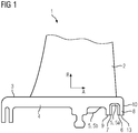
- the Figures 1 to 5 show schematic views of a guide vane 1 for a turbomachine according to a first embodiment of the present invention.
- the guide vane 1 comprises an airfoil 2 and a platform 3, to which the airfoil 2 is connected.
- the platform 3 is composed of a platform base part 4 and additional platform parts 5 in the form of a U-shaped metal profile sheet 5a with two opposing legs 6, 7 and in the form of an end sheet 5b, which are connected to the platform base part 4 by welding.
- the platform base part 4 comprises at its rear edge area in the axial flow direction A two immediately adjacent as well as parallel and spaced apart sealing lips 8, 9 for a seal to a rotating system of the turbomachine, which protrude radially from the side of the platform 3 facing away from the blade.
- the sealing lips 8, 9 are thus sealing partners of the seal pointing radially inward, which, as a corresponding sealing partner, comprise a friction surface (not shown) or a sealing lip that is likewise designed but pointing outward.
- the corresponding sealing partner is arranged on the rotor or part of a rotor blade.
- the rearmost sealing lip 8 in the axial flow direction A defines an end surface 10 of the platform 3.
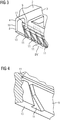
- cooling channels 12 are formed in the sealing lip 8, the outlet openings of which are arranged in a free end 13 of the sealing lip 8 pointing radially inward. From there, the cooling channels 12 each extend, starting from the rearmost sealing lip 8 in the axial flow direction A, slightly obliquely with respect to the radial direction R, that is, in the essentially radial direction R, and parallel to one another through the sealing lip 8.
- the cooling channel system comprises a connecting channel 14 which extends in the circumferential direction of the platform 3 and is provided at a distance from the free end 13 of the sealing lip 9, into which the cooling channels 12 open so that they are connected to one another.
- the connecting channel 14 extending approximately in the circumferential direction of the platform 3 is connected to a collecting channel 16 via a plurality of connecting channels 15 extending in the axial flow direction A.
- the collecting channel 16 is at least partially defined by a further additional platform part 5 in the form of a closing plate 5b, which is connected to the base platform part 4 by means of welding.
- the connecting channels 15 and the collecting channel 16 also form part of the cooling channel system.
- the cooling channel system has not only channels within a main section of the platform 3 but also in the sealing lip 8, the most uniform possible cooling of the platform 3 is achieved and strong temperature fluctuations within the material of the platform 3 are avoided.
- both the platform base part 4 and the additional platform parts 5 or 5a and 5b are made from the same nickel-based superalloy.
- the cooling fluid is fed to the cooling channel system of the guide vane, which then flows through the collecting channel 16 and the connecting channel 14 and can then flow through the cooling channels 12 to cool the sealing lip 8. Due to the outlet openings arranged in the free end 13, the cooling fluid finally contributes to improving the seal between the stator and rotor after leaving the guide vane.
- the shown second embodiment of a guide vane 1 according to the invention corresponds essentially to the first embodiment.
- the platform base part 4 only comprises the first sealing lip 8 of the two sealing lips 8, 9 at its rear edge region in the axial flow direction A.
- the first leg 6 of the U-shaped metal profile sheet 5a lies flat against the first sealing lip 8 and is connected to it by means of welding.
- the end plate 5b also has a leg 17 which is connected to the second leg 7 of the U-shaped metal profile plate 5a by welding in order to define the second sealing lip 9 of the two sealing lips 8, 9.
- grooves 11 are cast through the U-shaped metal profile sheet 5a and the closing sheet 5b are covered in order to partially define the six cooling channels 12 and the connecting channels 14, 15.
- the closing plate 5b defines the collecting channel 16 together with the platform base part 4.
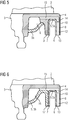
- FIG. 7 shows a third embodiment of a guide vane 1 according to the invention, in which the platform 3 is composed of a platform base part 4 and exactly one additional platform part 5, which is additively produced by means of selective laser melting and connected to the platform base part 4 by welding.
- the platform base part 4 does not include any sealing lip 8, 9.
- the platform additional part 5 defines two sealing lips 8, 9 connected via a strut 18 and an end plate 5b of the platform 3 connected to the sealing lips 8, 9.
- the additional platform part 5 completely defines the cooling channels 12 within the sealing lip 8, already mentioned in connection with the two previous embodiments, as well as the connecting channel 14 extending in the circumferential direction of the platform 3.
- the cooling channels 12 formed by means of an additive manufacturing process are very small, which is particularly advantageous when very narrow sealing lips are to be actively cooled.
- Turbulence elements are introduced into the cooling channels 12, which in Figure 7 are not shown for the sake of clarity. Such turbulence elements enable the heat transfer to be precisely adapted to the respective load on the platform 3.
- the connecting channels 15, which are also mentioned in connection with the two previous embodiments and extend in the axial flow direction A, are cast into the platform base part 4 and, like the collecting channel 16, are partially defined by the platform attachment part 5.
- the platform attachment 5 is welded to the platform base part 4 in such a way that the channels 12, 14 of the platform attachment 5 are in fluid connection with the further channels 15, 16.
- the fourth embodiment shown of a guide vane 1 according to the invention corresponds essentially to the third embodiment.
- the only difference is that the connecting channels 15, which extend in the axial flow direction A, are drilled into the platform base part 4 in the fourth embodiment and are therefore completely defined by the platform base part 4.
Landscapes
- Engineering & Computer Science (AREA)
- General Engineering & Computer Science (AREA)
- Mechanical Engineering (AREA)
- Turbine Rotor Nozzle Sealing (AREA)
- Sealing Devices (AREA)
- Powder Metallurgy (AREA)
Description
- Die vorliegende Erfindung betrifft eine Leitschaufel für eine Strömungsmaschine mit einem Schaufelblatt und zumindest einer Plattform, mit der das Schaufelblatt verbunden ist, wobei zur Kühlung der Plattform und des Schaufelblattes ein Kühlkanalsystem vorgesehen ist und wobei die Plattform an ihrer blattabgewandten Seite zumindest eine von der Plattform abstehende Dichtlippe für eine Abdichtung zu einem rotierenden System der Strömungsmaschine umfasst.
- In Strömungsmaschinen, wie etwa Gasturbinen, werden Turbinenschaufeln eingesetzt. Man unterscheidet grundsätzlich zwischen rotierenden Laufschaufeln und stationären Leitschaufeln, die ein heißes fluides Arbeitsmedium, insbesondere Gas, in Richtung der Laufschaufeln leiten. Insbesondere durch die hohe Temperatur des fluiden Arbeitsmediums und dem damit verbundenen hohen Wärmeeintrag aus dem fluiden Arbeitsmedium in die Turbinenschaufeln, sind die Turbinenschaufeln während ihres Betriebs hohen thermischen Belastungen ausgesetzt. Hierdurch können sich Beschädigungen an den Turbinenschaufeln ergeben.
- Um den hohen thermischen Belastungen von Turbinenschaufeln entgegenzutreten, werden Turbinenschaufeln zum einen häufig aus hochtemperaturfesten Metalllegierungen hergestellt. Zum anderen werden Turbinenschaufeln regelmäßig über ein Kühlkanalsystem aktiv mit einem Kühlfluid gekühlt. So ist es beispielsweise aus der
DE 10 2011 055 375 A1 und aus derEP 1 167 695 A1 bekannt, nach stromab überstehende Plattformüberhänge hohl und somit kühlbar auszugestalten. Dabei kann eine kombinierte Prall- und Filmkühlung der Plattform zum Einsatz gelangen. Darüber hinaus offenbart dieEP 1 211 384 A2 ein Verfahren zum Einbringen von schraubenförmigen Kühlkanälen in den Übergangsbereich einer Turbinenschaufel mittels einer wendelförmigen Erordierelektrode. - Vor diesem Hintergrund liegt der vorliegenden Erfindung die Aufgabe zugrunde, eine Leitschaufel der eingangs genannten Art mit einem effizienten Kühlkanalsystem bereitzustellen.
- Zur Lösung dieser Aufgabe schafft die vorliegende Erfindung eine Leitschaufel der eingangs genannten Art, die dadurch gekennzeichnet ist, dass sich durch die Dichtlippe mindestens ein Kühlkanal erstreckt, der einen Teil des Kühlkanalsystems bildet. Auf diese Weise kann auch die Dichtlippe aktiv gekühlt werden, wodurch sich eine effiziente und gleichmäßige Kühlung der gesamten Plattform ergibt. Somit werden starke Temperaturschwankungen innerhalb des Materials vermieden, die zu thermischen Spannungen führen und die Leitschaufel beschädigen können.
- Weiter ist eine Mehrzahl von Kühlkanälen vorgesehen, deren Austrittsöffnungen im freien Ende der Dichtlippe angeordnet sind. Die Kühlkanäle erstrecken sich jeweils ausgehend von einem freien Ende der Dichtlippe in zumindest im Wesentlichen radialer Richtung und somit parallel zur Abschlussfläche und insbesondere zumindest im Wesentlichen parallel zueinander durch die Dichtlippe. Durch mehrere Kühlkanäle, die sich auf die zuvor beschriebene Art und Weise erstrecken, wird eine besonders effiziente und gleichmäßige Kühlung der Dichtlippe erreicht. Zudem ergibt sich durch einen Austritt von Kühlluft aus den Kühlkanälen am freien, radial nach innen weisenden Ende der Dichtlippe während des bestimmungsgemäßen Einsatzes der Leitschaufel eine verbesserte Abdichtung des Spaltes zwischen der Dichtlippe und dem rotierenden System. Vorteilhaft ist zumindest ein Verbindungskanal beabstandet zu dem freien Ende der Dichtlippe vorgesehen, der die Mehrzahl von Kühlkanälen miteinander verbindet und ebenfalls einen Teil des Kühlkanalsystems bildet. Durch den Verbindungskanal, der sich bevorzugt in Umfangsrichtung erstreckt, kann das Kühlfluid den Kühlkanälen zentral zugeführt werden.
- Gemäß einer Ausgestaltung der Erfindung ist die zumindest eine Dichtlippe in einem in axialer Strömungsrichtung vorderen oder hinteren Randbereich der Plattform angeordnet und steht zumindest im Wesentlichen radial von der blattabgewandten Seite der Plattform derart ab, dass sie eine Abschlussfläche der Plattform definiert.
- Bevorzugt ist die Plattform aus einem Plattformbasisteil und zumindest einem damit verbundenen, bevorzugt angeschweißten oder angelöteten, Plattformzusatzteil zusammengesetzt, wobei der mindestens eine Kühlkanal und bevorzugt weitere Teile des Kühlkanalsystems zumindest teilweise durch das zumindest eine Plattformzusatzteil definiert ist/sind. Durch die mehrteilige, insbesondere zweiteilige, Ausbildung der Plattform lassen sich kleine Kühlkanäle ausbilden und somit insbesondere schmale Dichtlippen effektiv kühlen. Zudem werden der Guss und die mechanische Bearbeitung der Plattform durch die mehrteilige Ausbildung deutlich vereinfacht.
- Vorteilhaft ist in dem Plattformbasisteil mindestens eine Nut, insbesondere eine gießtechnisch hergestellte Nut, vorgesehen, die durch ein Plattformzusatzteil in Form eines Blechs, insbesondere eines Metallblechs, abgedeckt ist, um zumindest den mindestens einen Kühlkanal zu definieren. Es ist somit möglich, in nur wenigen Arbeitsschritten eine Mehrzahl von Kühlkanälen auszubilden.
- Die Plattform kann zwei unmittelbar benachbarte Dichtlippen an ihrer blattabgewandten Seite umfassen, die sich insbesondere zumindest im Wesentlichen parallel und beabstandet zueinander erstrecken.
- Zweckmäßigerweise ist das Plattformzusatzteil in Form eines U-förmigen Profilblechs vorgesehen, das derart zwischen den beiden Dichtlippen angeordnet ist, dass dessen gegenüberliegende Schenkel an den Dichtlippen flächig anliegen und die mindestens eine Nut abdecken.
- Alternativ kann das Plattformzusatzteil in Form eines U-förmigen Profilblechs vorgesehen sein, dessen erster Schenkel flächig an einer ersten der beiden Dichtlippen anliegt, um die darin vorgesehene mindestens eine Nut abzudecken, und dessen zweiter Schenkel mit einem Schenkel eines weiteren Plattformzusatzteils in Form eines Abschlussblechs verbunden, insbesondere daran geschweißt oder gelötet, ist, um die zweite der beiden Dichtlippen durch die beiden verbundenen Schenkel zu definieren.
- Zusätzlich oder alternativ zu einer Löt- oder Schweißverbindung ist es auch möglich, dass das U-förmige Profilblech zwischen den beiden Dichtlippen oder zwischen der Dichtlippe und dem Schenkel des Abschlussblechs festgeklemmt und somit kraftschlüssig gehalten ist. Bei Erwärmung der Plattform während des Betriebs dehnt sich der Werkstoff des Profilblechs schneller als der der Plattform aus, was die kraftschlüssige Verbindung noch verstärkt.
- Gemäß einer weiteren Alternative kann das Plattformzusatzteil in Form eines einteiligen Profilblechs mit einem U-förmigen Abschnitt, dessen erster Schenkel flächig an einer ersten der beiden Dichtlippen anliegt, um die darin vorgesehene mindestens eine Nut abzudecken, und dessen zweiter Schenkel die zweite der beiden Dichtlippen definiert, und einem sich daran anschließenden Abschlussblechabschnitt vorgesehen sein. Durch die einteilige Ausbildung des Profilblechs entfällt der Arbeitsschritt eines Verbindens eines Plattformzusatzteils in Form eines U-förmigen Profilblechs mit einem Plattformzusatzteil in Form eines Abschlussblechs mittels Löten oder Schweißen.
- Alternativ zu der mindestens einen Nut in dem Plattformbasisteil, die durch ein Plattformzusatzteil in Form eines Blechs abgedeckt ist, um den mindestens einen Kühlkanal zu definieren, kann das Plattformzusatzteil additiv, bevorzugt mittels selektiven Laserschmelzens, SLM, hergestellt sein und zumindest den mindestens einen Kühlkanal vollständig definieren. Somit wird das Plattformzusatzteil inklusive des darin ausgebildeten mindestens einen Kühlkanals einteilig in einem Arbeitsgang hergestellt.
- Durch die additive Fertigung kann das Plattformzusatzteil Kühlkanäle der unterschiedlichsten Formen aufweisen. Beispielsweise kann das Plattformzusatzteil sehr feine und/oder mikrostrukturartige Kühlkanäle aufweisen, die eine äußerst effiziente Nutzung des Kühlfluids, insbesondere Kühlluft, ermöglichen. Ebenso kann durch die additive Fertigung mindestens ein Turbulenzelement in den mindestens einen Kühlkanal eingebracht sein. Ein Turbulenzelement ermöglicht eine genaue Anpassung des Wärmeübergangs an die jeweilige Belastung der Plattform.
- Zweckmäßigerweise definiert das additiv hergestellte Plattformzusatzteil eine vollständige Dichtlippe mit dem mindestens einen Kühlkanal. Das additiv hergestellte Plattformzusatzteil kann auch zwei über eine Verstrebung verbundene Dichtlippen und ein mit den Dichtlippen verbundenes Abschlussblech definieren.
- Bevorzugt definiert das Plattformzusatzteil zusätzlich zu der Mehrzahl von Kühlkanälen zumindest teilweise auch den zuvor beschriebenen, die Mehrzahl von Kühlkanälen verbindenden Verbindungskanal oder weitere Teile des Kühlkanalsystems.
- Das Plattformbasisteil und/oder das zumindest eine Plattformzusatzteil können aus einer Superlegierung, bevorzugt einer Nickelbasis-Superlegierung, hergestellt sein. Vorteilhaft sind das Plattformbasisteil und das zumindest eine Plattformzusatzteil aus demselben Material, insbesondere aus einer Superlegierung, bevorzugt einer Nickelbasis-Superlegierung, hergestellt. Der Vorteil einer Nickelbasis-Superlegierung ist, dass diese eine ausreichende Temperaturfestigkeit sowie Oxidations- und Temperaturbeständigkeit aufweist.
- Alternativ zu der zuvor beschriebenen mehrteiligen Ausbildung der Plattform kann der zumindest eine Kühlkanal im Falle einer einteiligen Ausbildung der Plattform grundsätzlich auch als Bohrloch, insbesondere als ein mittels eines Erodiervorgangs eingebrachtes Bohrloch, ausgebildet sein.
- Weitere Merkmale und Vorteile der vorliegenden Erfindung werden anhand der nachfolgenden Beschreibung von vier Ausführungsformen einer Leitschaufel für eine Strömungsmaschine gemäß der vorliegenden Erfindung unter Bezugnahme auf die beiliegende Zeichnung deutlich. Darin ist
- Figur 1
- eine schematische Seitenansicht einer Leitschaufel gemäß einer ersten Ausführungsform der vorliegenden Erfindung;
- Figur 2
- eine schematische Ansicht eines Teils der Plattform der in
Figur 1 dargestellten Leitschaufel von schräg unten; - Figur 3
- eine schematische Ansicht eines Teils der Plattform der in
Figur 1 dargestellten Leitschaufel mit sichtbaren Kühl- und Verbindungskanälen von schräg unten; - Figur 4
- eine schematische, vergrößerte Ansicht des in
Figur 3 mit IV markierten Bereichs der Plattform; - Figur 5
- eine schematische Seitenansicht eines Teils der Plattform der in
Figur 1 dargestellten Leitschaufel, teilweise im Schnitt; - Figur 6
- eine schematische Seitenansicht eines Teils der Plattform einer Leitschaufel gemäß einer zweiten Ausführungsform der vorliegenden Erfindung, teilweise im Schnitt;
- Figur 7
- eine schematische Seitenansicht eines Teils der Plattform einer Leitschaufel gemäß einer dritten Ausführungsform der vorliegenden Erfindung, teilweise im Schnitt; und
- Figur 8
- eine schematische Seitenansicht eines Teils der Plattform einer Leitschaufel gemäß einer vierten Ausführungsform der vorliegenden Erfindung, teilweise im Schnitt.
- Die
Figuren 1 bis 5 zeigen schematische Ansichten einer Leitschaufel 1 für eine Strömungsmaschine gemäß einer ersten Ausführungsform der vorliegenden Erfindung. Hierbei umfasst die Leitschaufel 1 ein Schaufelblatt 2 und eine Plattform 3, mit der das Schaufelblatt 2 verbunden ist. Die Plattform 3 ist aus einem Plattformbasisteil 4 und Plattformzusatzteilen 5 in Form eines U-förmigen Metallprofilblechs 5a mit zwei gegenüberliegenden Schenkeln 6, 7 und in Form eines Abschlussblechs 5b zusammengesetzt, die mittels Schweißen mit dem Plattformbasisteil 4 verbunden sind. Das Plattformbasisteil 4 umfasst an seinem in axialer Strömungsrichtung A hinteren Randbereich zwei unmittelbar benachbarte sowie sich parallel und beabstandet zueinander erstreckende Dichtlippen 8, 9 für eine Abdichtung zu einem rotierenden System der Strömungsmaschine, die radial von der blattabgewandten Seite der Plattform 3 von dieser abstehen. Die Dichtlippen 8, 9 sind somit radial nach innen weisende Dichtungspartner der Abdichtung, die als korrespondierenden Dichtungspartner eine nicht dargestellte Reibfläche oder eine ebenso gestaltete, jedoch nach außen weisende Dichtlippe umfasst. Der korrespondierende Dichtungspartner ist am Rotor angeordnet oder Teil einer Rotorschaufel. Die in axialer Strömungsrichtung A hinterste Dichtlippe 8 definiert eine Abschlussfläche 10 der Plattform 3. - In dem Plattformbasisteil 4, insbesondere in der in axialer Strömungsrichtung A hintersten Dichtlippe 8, sind gießtechnisch hergestellte Nuten 11 vorgesehen. Das U-förmige Metallprofilblech 5a ist derart zwischen den beiden Dichtlippen 8, 9 angeordnet, dass dessen gegenüberliegende Schenkel 6, 7 an den Dichtlippen 8, 9 flächig anliegen, wodurch die Nuten 11 durch das Metallprofilblech 5a abgedeckt werden. Entsprechend werden Kühlkanäle 12 sowohl durch das Plattformbasisteil 4 als auch durch das Metallprofilblech 5a definiert, die einen Teil eines Kühlkanalsystems zur Kühlung der Leitschaufel 1 bilden. Durch die zweiteilige Ausbildung der Plattform 3 lassen sich insbesondere dünne Dichtlippen 8, 9 effizient aktiv kühlen.
- In der hier beschriebenen Ausführungsform sind in der Dichtlippe 8 sechs Kühlkanäle 12 ausgebildet, deren Austrittsöffnungen in einem radial nach innen weisenden freien Ende 13 der Dichtlippe 8 angeordnet sind. Von dort aus erstrecken sich die Kühlkanäle 12 jeweils ausgehend von der in axialer Strömungsrichtung A hintersten Dichtlippe 8 leicht schräg bezogen auf die radiale Richtung R, also in im Wesentlichen radialer Richtung R, und parallel zueinander durch die Dichtlippe 8.
- Zudem umfasst das Kühlkanalsystem einen sich in Umfangsrichtung der Plattform 3 erstreckenden und beabstandet zu dem freien Ende 13 der Dichtlippe 9 vorgesehenen Verbindungskanal 14, in den die Kühlkanäle 12 münden, so dass diese miteinander verbunden sind. Der sich etwa in Umfangsrichtung der Plattform 3 erstreckende Verbindungskanal 14 ist über eine Mehrzahl von sich in axialer Strömungsrichtung A erstreckenden Verbindungskanälen 15 mit einem Sammelkanal 16 verbunden. Der Sammelkanal 16 ist zumindest teilweise durch ein weiteres Plattformzusatzteil 5 in Form eines Abschlussblechs 5b definiert, das mit dem Plattformbasisteil 4 mittels Schweißen verbunden ist. Die Verbindungskanäle 15 und der Sammelkanal 16 bilden ebenfalls einen Teil des Kühlkanalsystems.
- Indem das Kühlkanalsystem nicht nur Kanäle innerhalb eines Hauptabschnitts der Plattform 3 sondern auch in der Dichtlippe 8 aufweist, wird eine möglichst gleichmäßige Kühlung der Plattform 3 erreicht und werden starke Temperaturschwankungen innerhalb des Materials der Plattform 3 vermieden.
- Bei der zuvor beschriebenen Ausführungsform sind sowohl das Plattformbasisteil 4 als auch die Plattformzusatzteile 5 bzw. 5a und 5b aus derselben Nickelbasis-Superlegierung hergestellt.
- Im Betrieb wird das Kühlfuid dem Kühlkanalsystem der Leitschaufel zugeführt, welches anschließend den Sammelkanal 16 und den Verbindungskanal 14 durchströmt und danach zur Kühlung der Dichtlippe 8 die Kühlkanäle 12 durchströmen kann. Aufgrund der im freien Ende 13 angeordneten Austrittsöffnungen trägt das Kühlfluid nach Verlassen der Leitschaufel abschließend zur Verbesserung der Abdichtung zwischen Stator und Rotor bei.
- Die in der
Figur 6 gezeigte zweite Ausführungsform einer erfindungsgemäßen Leitschaufel 1 entspricht im Wesentlichen der ersten Ausführungsform. Der einzige Unterschied besteht darin, dass bei der zweiten Ausführungsform das Plattformbasisteil 4 an seinem in axialer Strömungsrichtung A hinteren Randbereich nur die erste Dichtlippe 8 der beiden Dichtlippen 8, 9 umfasst. Wie bereits in der ersten Ausführungsform, liegt auch in der zweiten Ausführungsform der erste Schenkel 6 des U-förmigen Metallprofilblechs 5a flächig an der ersten Dichtlippe 8 an und ist mit dieser mittels Schweißen verbunden. Jedoch weist bei der zweiten Ausführungsform auch das Abschlussblech 5b einen Schenkel 17 auf, der mit dem zweiten Schenkel 7 des U-förmigen Metallprofilblechs 5a mittels Schweißen verbunden ist, um die zweite Dichtlippe 9 der beiden Dichtlippen 8, 9 zu definieren. In das Plattformbasisteil 4, insbesondere die erste Dichtlippe 8, sind Nuten 11 eingegossen, die durch das U-förmige Metallprofilblech 5a und das Abschlussblech 5b abgedeckt sind, um die sechs Kühlkanäle 12 und die Verbindungskanäle 14, 15 teilweise zu definieren. Zudem definiert das Abschlussblech 5b gemeinsam mit dem Plattformbasisteil 4 den Sammelkanal 16. -
Figur 7 zeigt eine dritte Ausführungsform einer erfindungsgemäßen Leitschaufel 1, bei der die Plattform 3 aus einem Plattformbasisteil 4 und genau einem Plattformzusatzteil 5 zusammengesetzt ist, das additiv mittels selektiven Laserschmelzens hergestellt und mittels Schweißen mit dem Plattformbasisteil 4 verbunden ist. Das Plattformbasisteil 4 umfasst bei der dritten Ausführungsform gar keine Dichtlippe 8, 9. Anstatt dessen definiert das Plattformzusatzteil 5 zwei über eine Verstrebung 18 verbundene Dichtlippen 8, 9 und ein mit den Dichtlippen 8, 9 verbundenes Abschlussblech 5b der Plattform 3. - Zudem definiert das Plattformzusatzteil 5 die bereits im Zusammenhang mit den beiden vorherigen Ausführungsformen erwähnten Kühlkanäle 12 innerhalb der Dichtlippe 8 sowie den sich in Umfangsrichtung der Plattform 3 erstreckenden Verbindungskanal 14 vollständig. Die mittels eines additiven Fertigungsverfahrens ausgebildeten Kühlkanäle 12 sind sehr klein, was insbesondere von Vorteil ist, wenn sehr schmale Dichtlippen aktiv gekühlt werden sollen. In die Kühlkanäle 12 sind Turbulenzelemente eingebracht, die in
Figur 7 der Übersichtlichkeit halber nicht gezeigt sind. Solche Turbulenzelemente ermöglichen eine genaue Anpassung des Wärmeübergangs an die jeweilige Belastung der Plattform 3. - Die ebenfalls bereits im Zusammenhang mit den beiden vorherigen Ausführungsformen erwähnten, sich in axialer Strömungsrichtung A erstreckenden Verbindungskanäle 15 sind bei der dritten Ausführungsform in das Plattformbasisteil 4 eingegossen und ebenso wie der Sammelkanal 16 teilweise durch das Plattformzusatzteil 5 definiert.
- Wie in der
Figur 8 zu sehen, ist das Plattformzusatzteil 5 derart an das Plattformbasisteil 4 geschweißt, dass die Kanäle 12, 14 des Plattformzusatzteils 5 mit den weiteren Kanälen 15, 16 in Fluidverbindung stehen. - Die in der
Figur 8 gezeigte vierte Ausführungsform einer erfindungsgemäßen Leitschaufel 1 entspricht im Wesentlichen der dritten Ausführungsform. Der einzige Unterschied besteht darin, dass die sich in axialer Strömungsrichtung A erstreckenden Verbindungskanäle 15 bei der vierten Ausführungsform in das Plattformbasisteil 4 gebohrt und daher vollständig durch das Plattformbasisteil 4 definiert sind. - Obwohl die Erfindung im Detail durch die bevorzugten Ausführungsbeispiele näher illustriert und beschrieben wurde, so ist die Erfindung nicht durch die offenbarten Beispiele eingeschränkt und andere Variationen können vom Fachmann hieraus abgeleitet werden, ohne den Schutzumfang der Erfindung zu verlassen.
Claims (14)
- Leitschaufel (1) für eine Strömungsmaschine mit einem Schaufelblatt (2) und zumindest einer Plattform (3), mit der das Schaufelblatt (2) verbunden ist, wobei zur Kühlung der Plattform (3) und des Schaufelblattes (2) ein Kühlkanalsystem vorgesehen ist und wobei die Plattform (3) an ihrer blattabgewandten Seite zumindest eine von der Plattform abstehende Dichtlippe (8, 9) für eine Abdichtung zu einem rotierenden System der Strömungsmaschine umfasst,
wobei sich durch die Dichtlippe (8, 9) mindestens ein Kühlkanal (12) erstreckt, der einen Teil des Kühlkanalsystems bildet,
dadurch gekennzeichnet, dass
eine Mehrzahl von Kühlkanälen (12) vorgesehen ist, deren Austrittsöffnungen im freien Ende (13) der Dichtlippe angeordnet sind und
dass sich die Kühlkanäle (12) jeweils ausgehend von einem freien Ende (13) der Dichtlippe (8, 9) in zumindest im Wesentlichen radialer Richtung (R) und insbesondere zumindest im Wesentlichen parallel zueinander durch die Dichtlippe (8, 9) erstrecken. - Leitschaufel (1) nach Anspruch 1,
dadurch gekennzeichnet, dass
die zumindest eine Dichtlippe (8, 9) in einem in axialer Strömungsrichtung (A) vorderen oder hinteren Randbereich der Plattform (3) angeordnet ist und zumindest im Wesentlichen radial von der blattabgewandten Seite der Plattform (3) derart absteht, dass sie eine weitestgehend parallel zu der radialen Richtung (R) sich erstreckende Abschlussfläche (10) der Plattform (3) definiert. - Leitschaufel (1) nach Anspruch 1 oder 2,
dadurch gekennzeichnet, dass
beabstandet zu dem freien Ende (13) der Dichtlippe (8, 9) zumindest ein Verbindungskanal (14) vorgesehen ist, der die Mehrzahl von Kühlkanälen (12) miteinander verbindet und einen Teil des Kühlkanalsystems bildet. - Leitschaufel (1) nach einem der vorherigen Ansprüche,
dadurch gekennzeichnet, dass
die Plattform (3) aus einem Plattformbasisteil (4) und zumindest einem damit verbundenen, bevorzugt angeschweißten oder angelöteten, Plattformzusatzteil (5) zusammengesetzt ist, wobei der mindestens eine Kühlkanal (12) und bevorzugt weitere Teile (14, 15, 16) des Kühlkanalsystems zumindest teilweise durch das zumindest eine Plattformzusatzteil (5) definiert ist/sind. - Leitschaufel (1) nach Anspruch 4,
dadurch gekennzeichnet, dass
in dem Plattformbasisteil (4) mindestens eine Nut (11), insbesondere eine gießtechnisch hergestellte Nut (11), vorgesehen ist, die durch ein Plattformzusatzteil (5) in Form eines Blechs, insbesondere eines Metallblechs, abgedeckt ist, um zumindest den mindestens einen Kühlkanal (12) zu definieren. - Leitschaufel (1) nach einem der vorherigen Ansprüche,
dadurch gekennzeichnet, dass
die Plattform (3) zwei unmittelbar benachbarte Dichtlippen (8, 9) an ihrer blattabgewandten Seite umfasst, die sich insbesondere zumindest im Wesentlichen parallel und beabstandet zueinander erstrecken. - Leitschaufel (1) nach den Ansprüchen 5 und 6,
dadurch gekennzeichnet, dass
das Plattformzusatzteil (5) in Form eines U-förmigen Profilblechs (5a) vorgesehen ist, das derart zwischen den beiden Dichtlippen (8, 9) angeordnet ist, dass dessen gegenüberliegende Schenkel (6, 7) an den Dichtlippen (8, 9) flächig anliegen und die mindestens eine Nut (11) abdecken. - Leitschaufel (1) nach den Ansprüchen 5 und 6,
dadurch gekennzeichnet, dass
das Plattformzusatzteil (5) in Form eines U-förmigen Profilblechs (5a) vorgesehen ist, dessen erster Schenkel (6) flächig an einer ersten (8) der beiden Dichtlippen (8, 9) anliegt, um die darin vorgesehene mindestens eine Nut (11) abzudecken, und dessen zweiter Schenkel (7) mit einem Schenkel (17) eines weiteren Plattformzusatzteils (5) in Form eines Abschlussblechs (5b) verbunden, insbesondere daran geschweißt oder gelötet, ist, um die zweite (9) der beiden Dichtlippen (8, 9) durch die beiden verbundenen Schenkel (7, 17) zu definieren. - Leitschaufel (1) nach den Ansprüchen 5 und 6,
dadurch gekennzeichnet, dass
das Plattformzusatzteil (5) in Form eines einteiligen Profilblechs mit einem U-förmigen Abschnitt, dessen erster Schenkel flächig an einer ersten (8) der beiden Dichtlippen (8, 9) anliegt, um die darin vorgesehene mindestens eine Nut (11) abzudecken, und dessen zweiter Schenkel die zweite (9) der beiden Dichtlippen (8, 9) definiert, und einem sich daran anschließenden Abschlussblechabschnitt vorgesehen ist. - Leitschaufel (1) nach Anspruch 4,
dadurch gekennzeichnet, dass
das Plattformzusatzteil (5) additiv, bevorzugt mittels selektiven Laserschmelzens, SLM, hergestellt ist und zumindest den mindestens einen Kühlkanal (12) vollständig definiert. - Leitschaufel (1) nach Anspruch 10,
dadurch gekennzeichnet, dass
das Plattformzusatzteil (5) zwei über eine Verstrebung (18) verbundene Dichtlippen (8, 9) und ein mit den Dichtlippen (8, 9) verbundenes Abschlussblech (5b) definiert. - Leitschaufel (1) nach Anspruch 10 oder 11,
dadurch gekennzeichnet, dass
in den mindestens einen Kühlkanal (12) mindestens ein Turbulenzelement eingebracht ist. - Leitschaufel (1) nach einem der Ansprüche 4 bis 12,
dadurch gekennzeichnet, dass
das Plattformbasisteil (4) und/oder das zumindest eine Plattformzusatzteil (5) aus einer Superlegierung, bevorzugt einer Nickelbasis-Superlegierung, hergestellt ist/sind. - Leitschaufel (1) nach einem der Ansprüche 4 bis 12,
dadurch gekennzeichnet, dass
das Plattformbasisteil (4) und das zumindest eine Plattformzusatzteil (5) aus demselben Material, insbesondere aus einer Superlegierung, bevorzugt einer Nickelbasis-Superlegierung, hergestellt sind.
Applications Claiming Priority (2)
| Application Number | Priority Date | Filing Date | Title |
|---|---|---|---|
| EP17155609.5A EP3361056A1 (de) | 2017-02-10 | 2017-02-10 | Leitschaufel für eine strömungsmaschine |
| PCT/EP2018/052879 WO2018146062A1 (de) | 2017-02-10 | 2018-02-06 | Leitschaufel für eine strömungsmaschine |
Publications (2)
| Publication Number | Publication Date |
|---|---|
| EP3551853A1 EP3551853A1 (de) | 2019-10-16 |
| EP3551853B1 true EP3551853B1 (de) | 2020-12-09 |
Family
ID=58016620
Family Applications (2)
| Application Number | Title | Priority Date | Filing Date |
|---|---|---|---|
| EP17155609.5A Withdrawn EP3361056A1 (de) | 2017-02-10 | 2017-02-10 | Leitschaufel für eine strömungsmaschine |
| EP18707247.5A Active EP3551853B1 (de) | 2017-02-10 | 2018-02-06 | Leitschaufel für eine strömungsmaschine |
Family Applications Before (1)
| Application Number | Title | Priority Date | Filing Date |
|---|---|---|---|
| EP17155609.5A Withdrawn EP3361056A1 (de) | 2017-02-10 | 2017-02-10 | Leitschaufel für eine strömungsmaschine |
Country Status (5)
| Country | Link |
|---|---|
| US (1) | US11174753B2 (de) |
| EP (2) | EP3361056A1 (de) |
| JP (1) | JP6854906B2 (de) |
| CN (1) | CN110325708B (de) |
| WO (1) | WO2018146062A1 (de) |
Families Citing this family (1)
| Publication number | Priority date | Publication date | Assignee | Title |
|---|---|---|---|---|
| CN112696236B (zh) * | 2020-11-10 | 2025-01-10 | 苏州西热节能环保技术有限公司 | 一种基于周向相对速度的密封结构 |
Family Cites Families (15)
| Publication number | Priority date | Publication date | Assignee | Title |
|---|---|---|---|---|
| EP1167695A1 (de) * | 2000-06-21 | 2002-01-02 | Siemens Aktiengesellschaft | Gasturbine und Gasturbinenleitschaufel |
| DE10059997B4 (de) * | 2000-12-02 | 2014-09-11 | Alstom Technology Ltd. | Kühlbare Schaufel für eine Gasturbinenkomponente |
| US20060269409A1 (en) | 2005-05-27 | 2006-11-30 | Mitsubishi Heavy Industries, Ltd. | Gas turbine moving blade having a platform, a method of forming the moving blade, a sealing plate, and a gas turbine having these elements |
| FR2907157A1 (fr) * | 2006-10-13 | 2008-04-18 | Snecma Sa | Aube mobile de turbomachine |
| US8277177B2 (en) * | 2009-01-19 | 2012-10-02 | Siemens Energy, Inc. | Fluidic rim seal system for turbine engines |
| US8851845B2 (en) * | 2010-11-17 | 2014-10-07 | General Electric Company | Turbomachine vane and method of cooling a turbomachine vane |
| US9309783B2 (en) * | 2013-01-10 | 2016-04-12 | General Electric Company | Seal assembly for turbine system |
| US9828872B2 (en) | 2013-02-07 | 2017-11-28 | General Electric Company | Cooling structure for turbomachine |
| EP2787170A1 (de) * | 2013-04-04 | 2014-10-08 | Siemens Aktiengesellschaft | Technik zum Kühlen der Fuß-Seitenfläche einer Plattform eines Turbomaschinenteils |
| FR3006366B1 (fr) * | 2013-05-28 | 2018-03-02 | Safran Aircraft Engines | Roue de turbine dans une turbomachine |
| JP5676040B1 (ja) * | 2014-06-30 | 2015-02-25 | 三菱日立パワーシステムズ株式会社 | 静翼、これを備えているガスタービン、静翼の製造方法、及び静翼の改造方法 |
| US9982542B2 (en) * | 2014-07-21 | 2018-05-29 | United Technologies Corporation | Airfoil platform impingement cooling holes |
| US9765699B2 (en) * | 2014-12-30 | 2017-09-19 | General Electric Company | Gas turbine sealing |
| EP3064715B1 (de) * | 2015-03-02 | 2019-04-10 | Rolls-Royce Corporation | Schaufel einer gasturbine und herstellungsverfahren |
| US10697313B2 (en) * | 2017-02-01 | 2020-06-30 | General Electric Company | Turbine engine component with an insert |
-
2017
- 2017-02-10 EP EP17155609.5A patent/EP3361056A1/de not_active Withdrawn
-
2018
- 2018-02-06 WO PCT/EP2018/052879 patent/WO2018146062A1/de not_active Ceased
- 2018-02-06 US US16/483,427 patent/US11174753B2/en active Active
- 2018-02-06 EP EP18707247.5A patent/EP3551853B1/de active Active
- 2018-02-06 CN CN201880011154.7A patent/CN110325708B/zh active Active
- 2018-02-06 JP JP2019543317A patent/JP6854906B2/ja not_active Expired - Fee Related
Non-Patent Citations (1)
| Title |
|---|
| None * |
Also Published As
| Publication number | Publication date |
|---|---|
| US20200011200A1 (en) | 2020-01-09 |
| US11174753B2 (en) | 2021-11-16 |
| EP3361056A1 (de) | 2018-08-15 |
| CN110325708B (zh) | 2022-04-19 |
| JP6854906B2 (ja) | 2021-04-07 |
| JP2020510776A (ja) | 2020-04-09 |
| CN110325708A (zh) | 2019-10-11 |
| EP3551853A1 (de) | 2019-10-16 |
| WO2018146062A1 (de) | 2018-08-16 |
Similar Documents
| Publication | Publication Date | Title |
|---|---|---|
| DE3211139C1 (de) | Axialturbinenschaufel,insbesondere Axialturbinenlaufschaufel fuer Gasturbinentriebwerke | |
| DE60018817T2 (de) | Gekühlte Gasturbinenschaufel | |
| DE2245599A1 (de) | Reibgeschweisster metallgegenstand und verfahren zu seiner herstellung | |
| CH711981A2 (de) | Kühlsystem für eine mehrwandige Schaufel. | |
| EP3040560B1 (de) | Gehäusevorrichtung für eine verdichterstufe einer mehrstufig ausgeführten verdichtervorrichtung und verfahren zur herstellung einer gehäusevorrichtung | |
| DE102011056321B4 (de) | Singlet-Leitapparatkonstruktion einer Dampfturbine für eine von hinten bestückte Anordnung und Dampfturbine mit derartiger Singlet-Leitapparatkonstruktion | |
| DE102014110332A1 (de) | Schaufelblatt mit einer Hinterkantenergänzungsstruktur | |
| DE102010016620A1 (de) | Turbinenleitapparat mit Seitenwandkühlplenum | |
| DE102014109182A1 (de) | Turbinenkomponente und Verfahren zur Herstellung derselben | |
| EP3051068A1 (de) | Leitschaufelring für eine strömungsmaschine und additives herstellungsverfahren | |
| DE102008014680A1 (de) | Leitgitteranordnung eines Abgasturboladers, Abgasturbolader und Verfahren zur Herstellung einer Leitgitteranordnung | |
| DE102004026503A1 (de) | Düsenzwischenstufendichtung für Dampfturbinen | |
| EP2823152A1 (de) | Turbinenlaufschaufel und axialer rotorabschnitt für eine gasturbine | |
| DE102011084153B4 (de) | Sicherungsvorrichtung zur Sicherung eines Schaufelelements in einer Nut einer Laufscheibe | |
| EP3456923B1 (de) | Schaufel einer strömungsmaschine mit kühlkanal und darin angeordnetem verdrängungskörper sowie verfahren zur herstellung | |
| DE60313782T2 (de) | Verfahren zur herstellung eines stator- oder rotorteils | |
| WO2009100864A2 (de) | Turbinengehäuse und verfahren zum herstellen eines turbinengehäuses | |
| EP3551853B1 (de) | Leitschaufel für eine strömungsmaschine | |
| EP3628030B1 (de) | Verfahren zum instandhalten einer strömungsmaschine | |
| DE2130128A1 (de) | Verfahren zum Verbinden des Schaufelblattes einer Stroemungsmaschinen-,insbesondere Turbomaschinen-Schaufel,mit einem Deckbandstueck | |
| EP3514333B1 (de) | Rotorschaufeldeckband für eine strömungsmaschine, rotorschaufel, verfahren zum herstellen eines rotorschaufeldeckbands und einer rotorschaufel | |
| EP3023191A1 (de) | Turbinenschaufel hergestellt aus zwei teilen | |
| EP0882545A2 (de) | Verfahren zum Reparieren von integral gegossenen Leitkränzen einer Turbine | |
| DE4203655C2 (de) | Verfahren zur Herstellung eines Strömungsleitringes für Turbinen | |
| EP4058657B1 (de) | Leitschaufelkranz mit verschleisselementen |
Legal Events
| Date | Code | Title | Description |
|---|---|---|---|
| STAA | Information on the status of an ep patent application or granted ep patent |
Free format text: STATUS: UNKNOWN |
|
| STAA | Information on the status of an ep patent application or granted ep patent |
Free format text: STATUS: THE INTERNATIONAL PUBLICATION HAS BEEN MADE |
|
| PUAI | Public reference made under article 153(3) epc to a published international application that has entered the european phase |
Free format text: ORIGINAL CODE: 0009012 |
|
| STAA | Information on the status of an ep patent application or granted ep patent |
Free format text: STATUS: REQUEST FOR EXAMINATION WAS MADE |
|
| 17P | Request for examination filed |
Effective date: 20190710 |
|
| AK | Designated contracting states |
Kind code of ref document: A1 Designated state(s): AL AT BE BG CH CY CZ DE DK EE ES FI FR GB GR HR HU IE IS IT LI LT LU LV MC MK MT NL NO PL PT RO RS SE SI SK SM TR |
|
| AX | Request for extension of the european patent |
Extension state: BA ME |
|
| DAV | Request for validation of the european patent (deleted) | ||
| DAX | Request for extension of the european patent (deleted) | ||
| GRAP | Despatch of communication of intention to grant a patent |
Free format text: ORIGINAL CODE: EPIDOSNIGR1 |
|
| STAA | Information on the status of an ep patent application or granted ep patent |
Free format text: STATUS: GRANT OF PATENT IS INTENDED |
|
| INTG | Intention to grant announced |
Effective date: 20200717 |
|
| GRAS | Grant fee paid |
Free format text: ORIGINAL CODE: EPIDOSNIGR3 |
|
| GRAA | (expected) grant |
Free format text: ORIGINAL CODE: 0009210 |
|
| STAA | Information on the status of an ep patent application or granted ep patent |
Free format text: STATUS: THE PATENT HAS BEEN GRANTED |
|
| AK | Designated contracting states |
Kind code of ref document: B1 Designated state(s): AL AT BE BG CH CY CZ DE DK EE ES FI FR GB GR HR HU IE IS IT LI LT LU LV MC MK MT NL NO PL PT RO RS SE SI SK SM TR |
|
| REG | Reference to a national code |
Ref country code: GB Ref legal event code: FG4D Free format text: NOT ENGLISH |
|
| REG | Reference to a national code |
Ref country code: AT Ref legal event code: REF Ref document number: 1343659 Country of ref document: AT Kind code of ref document: T Effective date: 20201215 Ref country code: DE Ref legal event code: R081 Ref document number: 502018003269 Country of ref document: DE Owner name: SIEMENS ENERGY GLOBAL GMBH & CO. KG, DE Free format text: FORMER OWNER: SIEMENS AKTIENGESELLSCHAFT, 80333 MUENCHEN, DE Ref country code: CH Ref legal event code: EP |
|
| REG | Reference to a national code |
Ref country code: DE Ref legal event code: R096 Ref document number: 502018003269 Country of ref document: DE |
|
| REG | Reference to a national code |
Ref country code: IE Ref legal event code: FG4D Free format text: LANGUAGE OF EP DOCUMENT: GERMAN |
|
| RAP2 | Party data changed (patent owner data changed or rights of a patent transferred) |
Owner name: SIEMENS ENERGY GLOBAL GMBH & CO. KG |
|
| PG25 | Lapsed in a contracting state [announced via postgrant information from national office to epo] |
Ref country code: RS Free format text: LAPSE BECAUSE OF FAILURE TO SUBMIT A TRANSLATION OF THE DESCRIPTION OR TO PAY THE FEE WITHIN THE PRESCRIBED TIME-LIMIT Effective date: 20201209 Ref country code: FI Free format text: LAPSE BECAUSE OF FAILURE TO SUBMIT A TRANSLATION OF THE DESCRIPTION OR TO PAY THE FEE WITHIN THE PRESCRIBED TIME-LIMIT Effective date: 20201209 Ref country code: NO Free format text: LAPSE BECAUSE OF FAILURE TO SUBMIT A TRANSLATION OF THE DESCRIPTION OR TO PAY THE FEE WITHIN THE PRESCRIBED TIME-LIMIT Effective date: 20210309 Ref country code: GR Free format text: LAPSE BECAUSE OF FAILURE TO SUBMIT A TRANSLATION OF THE DESCRIPTION OR TO PAY THE FEE WITHIN THE PRESCRIBED TIME-LIMIT Effective date: 20210310 |
|
| PG25 | Lapsed in a contracting state [announced via postgrant information from national office to epo] |
Ref country code: BG Free format text: LAPSE BECAUSE OF FAILURE TO SUBMIT A TRANSLATION OF THE DESCRIPTION OR TO PAY THE FEE WITHIN THE PRESCRIBED TIME-LIMIT Effective date: 20210309 Ref country code: SE Free format text: LAPSE BECAUSE OF FAILURE TO SUBMIT A TRANSLATION OF THE DESCRIPTION OR TO PAY THE FEE WITHIN THE PRESCRIBED TIME-LIMIT Effective date: 20201209 Ref country code: LV Free format text: LAPSE BECAUSE OF FAILURE TO SUBMIT A TRANSLATION OF THE DESCRIPTION OR TO PAY THE FEE WITHIN THE PRESCRIBED TIME-LIMIT Effective date: 20201209 |
|
| REG | Reference to a national code |
Ref country code: NL Ref legal event code: MP Effective date: 20201209 |
|
| PG25 | Lapsed in a contracting state [announced via postgrant information from national office to epo] |
Ref country code: NL Free format text: LAPSE BECAUSE OF FAILURE TO SUBMIT A TRANSLATION OF THE DESCRIPTION OR TO PAY THE FEE WITHIN THE PRESCRIBED TIME-LIMIT Effective date: 20201209 Ref country code: HR Free format text: LAPSE BECAUSE OF FAILURE TO SUBMIT A TRANSLATION OF THE DESCRIPTION OR TO PAY THE FEE WITHIN THE PRESCRIBED TIME-LIMIT Effective date: 20201209 |
|
| REG | Reference to a national code |
Ref country code: LT Ref legal event code: MG9D |
|
| PG25 | Lapsed in a contracting state [announced via postgrant information from national office to epo] |
Ref country code: RO Free format text: LAPSE BECAUSE OF FAILURE TO SUBMIT A TRANSLATION OF THE DESCRIPTION OR TO PAY THE FEE WITHIN THE PRESCRIBED TIME-LIMIT Effective date: 20201209 Ref country code: PT Free format text: LAPSE BECAUSE OF FAILURE TO SUBMIT A TRANSLATION OF THE DESCRIPTION OR TO PAY THE FEE WITHIN THE PRESCRIBED TIME-LIMIT Effective date: 20210409 Ref country code: LT Free format text: LAPSE BECAUSE OF FAILURE TO SUBMIT A TRANSLATION OF THE DESCRIPTION OR TO PAY THE FEE WITHIN THE PRESCRIBED TIME-LIMIT Effective date: 20201209 Ref country code: SK Free format text: LAPSE BECAUSE OF FAILURE TO SUBMIT A TRANSLATION OF THE DESCRIPTION OR TO PAY THE FEE WITHIN THE PRESCRIBED TIME-LIMIT Effective date: 20201209 Ref country code: SM Free format text: LAPSE BECAUSE OF FAILURE TO SUBMIT A TRANSLATION OF THE DESCRIPTION OR TO PAY THE FEE WITHIN THE PRESCRIBED TIME-LIMIT Effective date: 20201209 Ref country code: CZ Free format text: LAPSE BECAUSE OF FAILURE TO SUBMIT A TRANSLATION OF THE DESCRIPTION OR TO PAY THE FEE WITHIN THE PRESCRIBED TIME-LIMIT Effective date: 20201209 Ref country code: EE Free format text: LAPSE BECAUSE OF FAILURE TO SUBMIT A TRANSLATION OF THE DESCRIPTION OR TO PAY THE FEE WITHIN THE PRESCRIBED TIME-LIMIT Effective date: 20201209 |
|
| PG25 | Lapsed in a contracting state [announced via postgrant information from national office to epo] |
Ref country code: PL Free format text: LAPSE BECAUSE OF FAILURE TO SUBMIT A TRANSLATION OF THE DESCRIPTION OR TO PAY THE FEE WITHIN THE PRESCRIBED TIME-LIMIT Effective date: 20201209 |
|
| REG | Reference to a national code |
Ref country code: DE Ref legal event code: R097 Ref document number: 502018003269 Country of ref document: DE |
|
| PG25 | Lapsed in a contracting state [announced via postgrant information from national office to epo] |
Ref country code: MC Free format text: LAPSE BECAUSE OF FAILURE TO SUBMIT A TRANSLATION OF THE DESCRIPTION OR TO PAY THE FEE WITHIN THE PRESCRIBED TIME-LIMIT Effective date: 20201209 Ref country code: IS Free format text: LAPSE BECAUSE OF FAILURE TO SUBMIT A TRANSLATION OF THE DESCRIPTION OR TO PAY THE FEE WITHIN THE PRESCRIBED TIME-LIMIT Effective date: 20210409 |
|
| PLBE | No opposition filed within time limit |
Free format text: ORIGINAL CODE: 0009261 |
|
| STAA | Information on the status of an ep patent application or granted ep patent |
Free format text: STATUS: NO OPPOSITION FILED WITHIN TIME LIMIT |
|
| REG | Reference to a national code |
Ref country code: BE Ref legal event code: MM Effective date: 20210228 |
|
| PG25 | Lapsed in a contracting state [announced via postgrant information from national office to epo] |
Ref country code: CH Free format text: LAPSE BECAUSE OF NON-PAYMENT OF DUE FEES Effective date: 20210228 Ref country code: AL Free format text: LAPSE BECAUSE OF FAILURE TO SUBMIT A TRANSLATION OF THE DESCRIPTION OR TO PAY THE FEE WITHIN THE PRESCRIBED TIME-LIMIT Effective date: 20201209 Ref country code: LI Free format text: LAPSE BECAUSE OF NON-PAYMENT OF DUE FEES Effective date: 20210228 Ref country code: LU Free format text: LAPSE BECAUSE OF NON-PAYMENT OF DUE FEES Effective date: 20210206 |
|
| 26N | No opposition filed |
Effective date: 20210910 |
|
| PG25 | Lapsed in a contracting state [announced via postgrant information from national office to epo] |
Ref country code: DK Free format text: LAPSE BECAUSE OF FAILURE TO SUBMIT A TRANSLATION OF THE DESCRIPTION OR TO PAY THE FEE WITHIN THE PRESCRIBED TIME-LIMIT Effective date: 20201209 Ref country code: SI Free format text: LAPSE BECAUSE OF FAILURE TO SUBMIT A TRANSLATION OF THE DESCRIPTION OR TO PAY THE FEE WITHIN THE PRESCRIBED TIME-LIMIT Effective date: 20201209 |
|
| REG | Reference to a national code |
Ref country code: GB Ref legal event code: 732E Free format text: REGISTERED BETWEEN 20211202 AND 20211209 |
|
| PG25 | Lapsed in a contracting state [announced via postgrant information from national office to epo] |
Ref country code: ES Free format text: LAPSE BECAUSE OF FAILURE TO SUBMIT A TRANSLATION OF THE DESCRIPTION OR TO PAY THE FEE WITHIN THE PRESCRIBED TIME-LIMIT Effective date: 20201209 Ref country code: IE Free format text: LAPSE BECAUSE OF NON-PAYMENT OF DUE FEES Effective date: 20210206 |
|
| PG25 | Lapsed in a contracting state [announced via postgrant information from national office to epo] |
Ref country code: IS Free format text: LAPSE BECAUSE OF FAILURE TO SUBMIT A TRANSLATION OF THE DESCRIPTION OR TO PAY THE FEE WITHIN THE PRESCRIBED TIME-LIMIT Effective date: 20210409 |
|
| PG25 | Lapsed in a contracting state [announced via postgrant information from national office to epo] |
Ref country code: BE Free format text: LAPSE BECAUSE OF NON-PAYMENT OF DUE FEES Effective date: 20210228 |
|
| PG25 | Lapsed in a contracting state [announced via postgrant information from national office to epo] |
Ref country code: CY Free format text: LAPSE BECAUSE OF FAILURE TO SUBMIT A TRANSLATION OF THE DESCRIPTION OR TO PAY THE FEE WITHIN THE PRESCRIBED TIME-LIMIT Effective date: 20201209 |
|
| PG25 | Lapsed in a contracting state [announced via postgrant information from national office to epo] |
Ref country code: HU Free format text: LAPSE BECAUSE OF FAILURE TO SUBMIT A TRANSLATION OF THE DESCRIPTION OR TO PAY THE FEE WITHIN THE PRESCRIBED TIME-LIMIT; INVALID AB INITIO Effective date: 20180206 |
|
| P01 | Opt-out of the competence of the unified patent court (upc) registered |
Effective date: 20231222 |
|
| REG | Reference to a national code |
Ref country code: AT Ref legal event code: MM01 Ref document number: 1343659 Country of ref document: AT Kind code of ref document: T Effective date: 20230206 |
|
| PG25 | Lapsed in a contracting state [announced via postgrant information from national office to epo] |
Ref country code: AT Free format text: LAPSE BECAUSE OF NON-PAYMENT OF DUE FEES Effective date: 20230206 |
|
| PG25 | Lapsed in a contracting state [announced via postgrant information from national office to epo] |
Ref country code: MK Free format text: LAPSE BECAUSE OF FAILURE TO SUBMIT A TRANSLATION OF THE DESCRIPTION OR TO PAY THE FEE WITHIN THE PRESCRIBED TIME-LIMIT Effective date: 20201209 Ref country code: AT Free format text: LAPSE BECAUSE OF NON-PAYMENT OF DUE FEES Effective date: 20230206 |
|
| PG25 | Lapsed in a contracting state [announced via postgrant information from national office to epo] |
Ref country code: MT Free format text: LAPSE BECAUSE OF FAILURE TO SUBMIT A TRANSLATION OF THE DESCRIPTION OR TO PAY THE FEE WITHIN THE PRESCRIBED TIME-LIMIT Effective date: 20201209 |
|
| PGFP | Annual fee paid to national office [announced via postgrant information from national office to epo] |
Ref country code: DE Payment date: 20250226 Year of fee payment: 8 |
|
| PGFP | Annual fee paid to national office [announced via postgrant information from national office to epo] |
Ref country code: FR Payment date: 20250224 Year of fee payment: 8 |
|
| PGFP | Annual fee paid to national office [announced via postgrant information from national office to epo] |
Ref country code: IT Payment date: 20250225 Year of fee payment: 8 Ref country code: GB Payment date: 20250218 Year of fee payment: 8 |
|
| PG25 | Lapsed in a contracting state [announced via postgrant information from national office to epo] |
Ref country code: TR Free format text: LAPSE BECAUSE OF FAILURE TO SUBMIT A TRANSLATION OF THE DESCRIPTION OR TO PAY THE FEE WITHIN THE PRESCRIBED TIME-LIMIT Effective date: 20201209 |