EP3551853B1 - Aube directrice pour une turbomachine - Google Patents
Aube directrice pour une turbomachine Download PDFInfo
- Publication number
- EP3551853B1 EP3551853B1 EP18707247.5A EP18707247A EP3551853B1 EP 3551853 B1 EP3551853 B1 EP 3551853B1 EP 18707247 A EP18707247 A EP 18707247A EP 3551853 B1 EP3551853 B1 EP 3551853B1
- Authority
- EP
- European Patent Office
- Prior art keywords
- platform
- guide vane
- cooling
- attachment part
- cooling duct
- Prior art date
- Legal status (The legal status is an assumption and is not a legal conclusion. Google has not performed a legal analysis and makes no representation as to the accuracy of the status listed.)
- Active
Links
- 238000001816 cooling Methods 0.000 claims description 66
- 238000007789 sealing Methods 0.000 claims description 55
- PXHVJJICTQNCMI-UHFFFAOYSA-N Nickel Chemical compound [Ni] PXHVJJICTQNCMI-UHFFFAOYSA-N 0.000 claims description 12
- 239000002184 metal Substances 0.000 claims description 12
- 229910052751 metal Inorganic materials 0.000 claims description 12
- 229910000601 superalloy Inorganic materials 0.000 claims description 10
- 229910052759 nickel Inorganic materials 0.000 claims description 6
- 239000000463 material Substances 0.000 claims description 5
- 239000000654 additive Substances 0.000 claims description 4
- 230000000996 additive effect Effects 0.000 claims description 4
- 238000005266 casting Methods 0.000 claims description 4
- 238000002844 melting Methods 0.000 claims description 3
- 230000008018 melting Effects 0.000 claims description 3
- 238000005516 engineering process Methods 0.000 claims description 2
- 230000002093 peripheral effect Effects 0.000 claims 1
- 238000003466 welding Methods 0.000 description 6
- 239000012809 cooling fluid Substances 0.000 description 5
- 239000012530 fluid Substances 0.000 description 5
- 238000004519 manufacturing process Methods 0.000 description 3
- 230000003628 erosive effect Effects 0.000 description 2
- 238000000034 method Methods 0.000 description 2
- 230000006378 damage Effects 0.000 description 1
- 229910001092 metal group alloy Inorganic materials 0.000 description 1
- 230000003647 oxidation Effects 0.000 description 1
- 238000007254 oxidation reaction Methods 0.000 description 1
- 238000005476 soldering Methods 0.000 description 1
- 230000003685 thermal hair damage Effects 0.000 description 1
- 230000008646 thermal stress Effects 0.000 description 1
- 230000007704 transition Effects 0.000 description 1
Images


Classifications
-
- F—MECHANICAL ENGINEERING; LIGHTING; HEATING; WEAPONS; BLASTING
- F01—MACHINES OR ENGINES IN GENERAL; ENGINE PLANTS IN GENERAL; STEAM ENGINES
- F01D—NON-POSITIVE DISPLACEMENT MACHINES OR ENGINES, e.g. STEAM TURBINES
- F01D25/00—Component parts, details, or accessories, not provided for in, or of interest apart from, other groups
- F01D25/08—Cooling; Heating; Heat-insulation
- F01D25/12—Cooling
-
- F—MECHANICAL ENGINEERING; LIGHTING; HEATING; WEAPONS; BLASTING
- F01—MACHINES OR ENGINES IN GENERAL; ENGINE PLANTS IN GENERAL; STEAM ENGINES
- F01D—NON-POSITIVE DISPLACEMENT MACHINES OR ENGINES, e.g. STEAM TURBINES
- F01D11/00—Preventing or minimising internal leakage of working-fluid, e.g. between stages
- F01D11/001—Preventing or minimising internal leakage of working-fluid, e.g. between stages for sealing space between stator blade and rotor
-
- F—MECHANICAL ENGINEERING; LIGHTING; HEATING; WEAPONS; BLASTING
- F01—MACHINES OR ENGINES IN GENERAL; ENGINE PLANTS IN GENERAL; STEAM ENGINES
- F01D—NON-POSITIVE DISPLACEMENT MACHINES OR ENGINES, e.g. STEAM TURBINES
- F01D11/00—Preventing or minimising internal leakage of working-fluid, e.g. between stages
- F01D11/02—Preventing or minimising internal leakage of working-fluid, e.g. between stages by non-contact sealings, e.g. of labyrinth type
- F01D11/025—Seal clearance control; Floating assembly; Adaptation means to differential thermal dilatations
-
- F—MECHANICAL ENGINEERING; LIGHTING; HEATING; WEAPONS; BLASTING
- F16—ENGINEERING ELEMENTS AND UNITS; GENERAL MEASURES FOR PRODUCING AND MAINTAINING EFFECTIVE FUNCTIONING OF MACHINES OR INSTALLATIONS; THERMAL INSULATION IN GENERAL
- F16J—PISTONS; CYLINDERS; SEALINGS
- F16J15/00—Sealings
- F16J15/44—Free-space packings
- F16J15/447—Labyrinth packings
-
- F—MECHANICAL ENGINEERING; LIGHTING; HEATING; WEAPONS; BLASTING
- F05—INDEXING SCHEMES RELATING TO ENGINES OR PUMPS IN VARIOUS SUBCLASSES OF CLASSES F01-F04
- F05D—INDEXING SCHEME FOR ASPECTS RELATING TO NON-POSITIVE-DISPLACEMENT MACHINES OR ENGINES, GAS-TURBINES OR JET-PROPULSION PLANTS
- F05D2230/00—Manufacture
- F05D2230/20—Manufacture essentially without removing material
- F05D2230/21—Manufacture essentially without removing material by casting
-
- F—MECHANICAL ENGINEERING; LIGHTING; HEATING; WEAPONS; BLASTING
- F05—INDEXING SCHEMES RELATING TO ENGINES OR PUMPS IN VARIOUS SUBCLASSES OF CLASSES F01-F04
- F05D—INDEXING SCHEME FOR ASPECTS RELATING TO NON-POSITIVE-DISPLACEMENT MACHINES OR ENGINES, GAS-TURBINES OR JET-PROPULSION PLANTS
- F05D2230/00—Manufacture
- F05D2230/20—Manufacture essentially without removing material
- F05D2230/23—Manufacture essentially without removing material by permanently joining parts together
- F05D2230/232—Manufacture essentially without removing material by permanently joining parts together by welding
- F05D2230/237—Brazing
-
- F—MECHANICAL ENGINEERING; LIGHTING; HEATING; WEAPONS; BLASTING
- F05—INDEXING SCHEMES RELATING TO ENGINES OR PUMPS IN VARIOUS SUBCLASSES OF CLASSES F01-F04
- F05D—INDEXING SCHEME FOR ASPECTS RELATING TO NON-POSITIVE-DISPLACEMENT MACHINES OR ENGINES, GAS-TURBINES OR JET-PROPULSION PLANTS
- F05D2230/00—Manufacture
- F05D2230/20—Manufacture essentially without removing material
- F05D2230/23—Manufacture essentially without removing material by permanently joining parts together
- F05D2230/232—Manufacture essentially without removing material by permanently joining parts together by welding
- F05D2230/238—Soldering
-
- F—MECHANICAL ENGINEERING; LIGHTING; HEATING; WEAPONS; BLASTING
- F05—INDEXING SCHEMES RELATING TO ENGINES OR PUMPS IN VARIOUS SUBCLASSES OF CLASSES F01-F04
- F05D—INDEXING SCHEME FOR ASPECTS RELATING TO NON-POSITIVE-DISPLACEMENT MACHINES OR ENGINES, GAS-TURBINES OR JET-PROPULSION PLANTS
- F05D2240/00—Components
- F05D2240/10—Stators
- F05D2240/12—Fluid guiding means, e.g. vanes
- F05D2240/126—Baffles or ribs
-
- F—MECHANICAL ENGINEERING; LIGHTING; HEATING; WEAPONS; BLASTING
- F05—INDEXING SCHEMES RELATING TO ENGINES OR PUMPS IN VARIOUS SUBCLASSES OF CLASSES F01-F04
- F05D—INDEXING SCHEME FOR ASPECTS RELATING TO NON-POSITIVE-DISPLACEMENT MACHINES OR ENGINES, GAS-TURBINES OR JET-PROPULSION PLANTS
- F05D2240/00—Components
- F05D2240/10—Stators
- F05D2240/12—Fluid guiding means, e.g. vanes
- F05D2240/127—Vortex generators, turbulators, or the like, for mixing
-
- F—MECHANICAL ENGINEERING; LIGHTING; HEATING; WEAPONS; BLASTING
- F05—INDEXING SCHEMES RELATING TO ENGINES OR PUMPS IN VARIOUS SUBCLASSES OF CLASSES F01-F04
- F05D—INDEXING SCHEME FOR ASPECTS RELATING TO NON-POSITIVE-DISPLACEMENT MACHINES OR ENGINES, GAS-TURBINES OR JET-PROPULSION PLANTS
- F05D2300/00—Materials; Properties thereof
- F05D2300/10—Metals, alloys or intermetallic compounds
- F05D2300/17—Alloys
- F05D2300/175—Superalloys
Definitions
- the present invention relates to a guide vane for a turbomachine with an airfoil and at least one platform to which the airfoil is connected, a cooling channel system being provided for cooling the platform and the airfoil and with the platform at least one protruding from the platform on its side facing away from the blade Sealing lip for a seal to a rotating system of the turbomachine includes.
- Turbine blades are used in fluid flow machines such as gas turbines.
- a fundamental distinction is made between rotating rotor blades and stationary guide blades, which guide a hot fluid working medium, in particular gas, in the direction of the rotor blades.
- the turbine blades are exposed to high thermal loads during their operation. This can damage the turbine blades.
- turbine blades are often made from high-temperature-resistant metal alloys.
- turbine blades are regularly actively cooled with a cooling fluid via a cooling channel system. So it is for example from the DE 10 2011 055 375 A1 and from the EP 1 167 695 A1 known to design hollow and thus coolable after protruding platform overhangs downstream. Combined impingement and film cooling of the platform can be used.
- the EP 1 211 384 A2 a method for introducing helical cooling channels into the transition area of a Turbine blade by means of a helical eroding electrode.
- the present invention is based on the object of providing a guide vane of the type mentioned above with an efficient cooling channel system.
- the present invention creates a guide vane of the type mentioned at the outset, which is characterized in that at least one cooling channel, which forms part of the cooling channel system, extends through the sealing lip.
- the sealing lip can also be actively cooled, which results in efficient and uniform cooling of the entire platform. This avoids strong temperature fluctuations within the material, which can lead to thermal stresses and damage the guide vane.
- a plurality of cooling channels is also provided, the outlet openings of which are arranged in the free end of the sealing lip.
- the cooling channels each extend, starting from a free end of the sealing lip, in an at least substantially radial direction and thus parallel to the end surface and in particular at least substantially parallel to one another through the sealing lip.
- a particularly efficient and uniform cooling of the sealing lip is achieved by several cooling channels which extend in the manner described above.
- the exit of cooling air from the cooling channels at the free, radially inwardly facing end of the sealing lip during the intended use of the guide vane results in an improved sealing of the gap between the sealing lip and the rotating system.
- At least one connecting channel is advantageously provided at a distance from the free end of the sealing lip, which connects the plurality of cooling channels to one another and also forms part of the cooling channel system.
- the cooling fluid can be fed centrally to the cooling channels through the connecting channel, which preferably extends in the circumferential direction.
- the at least one sealing lip is arranged in a front or rear edge region of the platform in the axial flow direction and protrudes at least substantially radially from the side of the platform facing away from the blade in such a way that it defines a closing surface of the platform.
- the platform is preferably composed of a platform base part and at least one connected, preferably welded or soldered, additional platform part, the at least one cooling channel and preferably further parts of the cooling channel system being at least partially defined by the at least one additional platform part. Due to the multi-part, in particular two-part, design of the platform, small cooling channels can be formed and thus narrow sealing lips in particular can be effectively cooled. In addition, the casting and the mechanical processing of the platform are significantly simplified by the multi-part design.
- At least one groove in particular a groove produced by casting, is advantageously provided in the platform base part, which is covered by an additional platform part in the form of a sheet metal, in particular a metal sheet, in order to define at least the at least one cooling channel. It is thus possible to form a plurality of cooling channels in just a few work steps.
- the platform can comprise two immediately adjacent sealing lips on its side facing away from the sheet, which in particular extend at least substantially parallel and spaced from one another.
- the additional platform part is expediently provided in the form of a U-shaped profiled sheet, which is arranged between the two sealing lips in such a way that its opposite legs lie flat against the sealing lips and cover the at least one groove.
- the additional platform part can be provided in the form of a U-shaped profile sheet, the first leg of which rests flat against a first of the two sealing lips to cover the at least one groove provided therein, and the second leg of which is connected to a leg of a further additional platform part in the form of an end plate , in particular welded or soldered to it, is to define the second of the two sealing lips by the two connected legs.
- the U-shaped profile sheet in addition or as an alternative to a soldered or welded connection, it is also possible for the U-shaped profile sheet to be clamped tightly between the two sealing lips or between the sealing lip and the leg of the end sheet and thus held in a force-locking manner. If the platform heats up during operation, the material of the profile sheet expands faster than that of the platform, which further strengthens the force-locking connection.
- the platform attachment can be in the form of a one-piece profiled sheet with a U-shaped section, the first leg of which rests flat against a first of the two sealing lips in order to cover the at least one groove provided therein, and the second leg of which defines the second of the two sealing lips , and an adjoining sheet metal section. Due to the one-piece design of the profiled sheet, the work step of connecting an additional platform part in the form of a U-shaped profiled sheet to an additional platform part in the form of an end sheet by means of soldering or welding is eliminated.
- the additional platform part can be additively, preferably by means of selective laser melting, SLM, be made and at least fully define the at least one cooling channel.
- SLM selective laser melting
- the additional platform part can have cooling channels of the most varied of shapes.
- the additional platform part can have very fine and / or microstructure-like cooling channels which enable extremely efficient use of the cooling fluid, in particular cooling air.
- At least one turbulence element can also be introduced into the at least one cooling channel through additive manufacturing. A turbulence element enables the heat transfer to be precisely adapted to the respective load on the platform.
- the additively manufactured additional platform part expediently defines a complete sealing lip with the at least one cooling channel.
- the additively manufactured additional platform part can also define two sealing lips connected via a strut and a cover plate connected to the sealing lips.
- the additional platform part preferably also defines at least partially the previously described connecting channel connecting the plurality of cooling channels or further parts of the cooling channel system.
- the platform base part and / or the at least one additional platform part can be made from a superalloy, preferably a nickel-based superalloy.
- the platform base part and the at least one additional platform part are advantageously made from the same material, in particular from a superalloy, preferably a nickel-based superalloy.
- the advantage of a nickel-based superalloy is that it has sufficient temperature resistance as well as oxidation and temperature resistance.
- the at least one cooling channel can in principle also be designed as a borehole, in particular as a borehole made by means of an erosion process.
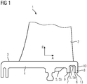
- the Figures 1 to 5 show schematic views of a guide vane 1 for a turbomachine according to a first embodiment of the present invention.
- the guide vane 1 comprises an airfoil 2 and a platform 3, to which the airfoil 2 is connected.
- the platform 3 is composed of a platform base part 4 and additional platform parts 5 in the form of a U-shaped metal profile sheet 5a with two opposing legs 6, 7 and in the form of an end sheet 5b, which are connected to the platform base part 4 by welding.
- the platform base part 4 comprises at its rear edge area in the axial flow direction A two immediately adjacent as well as parallel and spaced apart sealing lips 8, 9 for a seal to a rotating system of the turbomachine, which protrude radially from the side of the platform 3 facing away from the blade.
- the sealing lips 8, 9 are thus sealing partners of the seal pointing radially inward, which, as a corresponding sealing partner, comprise a friction surface (not shown) or a sealing lip that is likewise designed but pointing outward.
- the corresponding sealing partner is arranged on the rotor or part of a rotor blade.
- the rearmost sealing lip 8 in the axial flow direction A defines an end surface 10 of the platform 3.
- cooling channels 12 are formed in the sealing lip 8, the outlet openings of which are arranged in a free end 13 of the sealing lip 8 pointing radially inward. From there, the cooling channels 12 each extend, starting from the rearmost sealing lip 8 in the axial flow direction A, slightly obliquely with respect to the radial direction R, that is, in the essentially radial direction R, and parallel to one another through the sealing lip 8.
- the cooling channel system comprises a connecting channel 14 which extends in the circumferential direction of the platform 3 and is provided at a distance from the free end 13 of the sealing lip 9, into which the cooling channels 12 open so that they are connected to one another.
- the connecting channel 14 extending approximately in the circumferential direction of the platform 3 is connected to a collecting channel 16 via a plurality of connecting channels 15 extending in the axial flow direction A.
- the collecting channel 16 is at least partially defined by a further additional platform part 5 in the form of a closing plate 5b, which is connected to the base platform part 4 by means of welding.
- the connecting channels 15 and the collecting channel 16 also form part of the cooling channel system.
- the cooling channel system has not only channels within a main section of the platform 3 but also in the sealing lip 8, the most uniform possible cooling of the platform 3 is achieved and strong temperature fluctuations within the material of the platform 3 are avoided.
- both the platform base part 4 and the additional platform parts 5 or 5a and 5b are made from the same nickel-based superalloy.
- the cooling fluid is fed to the cooling channel system of the guide vane, which then flows through the collecting channel 16 and the connecting channel 14 and can then flow through the cooling channels 12 to cool the sealing lip 8. Due to the outlet openings arranged in the free end 13, the cooling fluid finally contributes to improving the seal between the stator and rotor after leaving the guide vane.
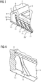
- the shown second embodiment of a guide vane 1 according to the invention corresponds essentially to the first embodiment.
- the platform base part 4 only comprises the first sealing lip 8 of the two sealing lips 8, 9 at its rear edge region in the axial flow direction A.
- the first leg 6 of the U-shaped metal profile sheet 5a lies flat against the first sealing lip 8 and is connected to it by means of welding.
- the end plate 5b also has a leg 17 which is connected to the second leg 7 of the U-shaped metal profile plate 5a by welding in order to define the second sealing lip 9 of the two sealing lips 8, 9.
- grooves 11 are cast through the U-shaped metal profile sheet 5a and the closing sheet 5b are covered in order to partially define the six cooling channels 12 and the connecting channels 14, 15.
- the closing plate 5b defines the collecting channel 16 together with the platform base part 4.
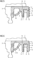
- FIG. 7 shows a third embodiment of a guide vane 1 according to the invention, in which the platform 3 is composed of a platform base part 4 and exactly one additional platform part 5, which is additively produced by means of selective laser melting and connected to the platform base part 4 by welding.
- the platform base part 4 does not include any sealing lip 8, 9.
- the platform additional part 5 defines two sealing lips 8, 9 connected via a strut 18 and an end plate 5b of the platform 3 connected to the sealing lips 8, 9.
- the additional platform part 5 completely defines the cooling channels 12 within the sealing lip 8, already mentioned in connection with the two previous embodiments, as well as the connecting channel 14 extending in the circumferential direction of the platform 3.
- the cooling channels 12 formed by means of an additive manufacturing process are very small, which is particularly advantageous when very narrow sealing lips are to be actively cooled.
- Turbulence elements are introduced into the cooling channels 12, which in Figure 7 are not shown for the sake of clarity. Such turbulence elements enable the heat transfer to be precisely adapted to the respective load on the platform 3.
- the connecting channels 15, which are also mentioned in connection with the two previous embodiments and extend in the axial flow direction A, are cast into the platform base part 4 and, like the collecting channel 16, are partially defined by the platform attachment part 5.
- the platform attachment 5 is welded to the platform base part 4 in such a way that the channels 12, 14 of the platform attachment 5 are in fluid connection with the further channels 15, 16.
- the fourth embodiment shown of a guide vane 1 according to the invention corresponds essentially to the third embodiment.
- the only difference is that the connecting channels 15, which extend in the axial flow direction A, are drilled into the platform base part 4 in the fourth embodiment and are therefore completely defined by the platform base part 4.
Landscapes
- Engineering & Computer Science (AREA)
- General Engineering & Computer Science (AREA)
- Mechanical Engineering (AREA)
- Turbine Rotor Nozzle Sealing (AREA)
- Sealing Devices (AREA)
- Powder Metallurgy (AREA)
Claims (14)
- Aube (1) directrice d'une turbomachine ayant un corps (2) d'aube et au moins une plateforme (3), à laquelle le corps (2) de l'aube est relié, dans laquelle il est prévu un système de conduit de refroidissement pour le refroidissement de la plateforme (3) et du corps (2) de l'aube et dans laquelle la plateforme (3) comprend, sur sa face loin du corps, au moins une lèvre (8, 9) d'étanchéité en saillie de la plateforme pour une étanchéité par rapport à un système tournant de la turbomachine, dans laquelle, dans la lèvre (8, 9) d'étanchéité, s'étend au moins un conduit (12) de refroidissement, qui forme une partie du système de conduit de refroidissement,
caractérisée en ce qu'
il est prévu une pluralité de conduits (12) de refroidissement, dont les ouvertures de sortie sont disposées à l'extrémité (13) libre de la lèvre d'étanchéité et
en ce que les conduits (12) de refroidissement s'étendent, respectivement, à partir d'une extrémité (13) libre de la lèvre (8, 9) d'étanchéité, dans au moins une direction (R) sensiblement radiale et notamment en étant sensiblement parallèles les uns aux autres, dans la lèvre (8, 9) d'étanchéité. - Aube (1) directrice suivant la revendication 1,
caractérisée en ce que
la au moins une lèvre (8, 9) d'étanchéité est disposée dans une partie de bord, avant ou arrière dans la direction (A) axiale d'écoulement, de la plateforme (3) et fait saillie, au moins sensiblement radialement du côté, loin du corps, de la plateforme (3), de manière à définir une surface (10) de fermeture, s'étendant dans une grande mesure parallèlement à la direction (R) radiale, de la plateforme (3). - Aube (1) directrice suivant la revendication 1 ou 2,
caractérisée en ce qu'
à distance de l'extrémité (13) libre de la lèvre (8, 9) d'étanchéité, est prévu au moins un conduit (14) de communication, qui met la pluralité de conduits (12) de refroidissement en communication entre eux et qui forme une partie du système de conduit de refroidissement. - Aube (1) directrice suivant l'une des revendications précédentes,
caractérisée en ce que
la plateforme (3) est composée d'une partie (4) de base et d'au moins une partie (5) supplémentaire, qui y est reliée, en y étant de préférence soudée ou brasée, le au moins un conduit (12) de refroidissement, et de préférence d'autres parties (14, 15, 16) du système de conduit de refroidissement, étant défini, au moins en partie, par la au moins une partie (5) supplémentaire de la plateforme. - Aube (1) directrice suivant la revendication 4,
caractérisée en ce que,
dans la partie (4) de base de la plateforme, est prévue au moins une rainure (11), notamment une rainure (11) fabriquée en technique de coulée, qui est recouverte par une partie (5) supplémentaire de la plateforme sous la forme d'une tôle, notamment d'une tôle métallique, afin de définir au moins le au moins un conduit (12) de refroidissement. - Aube (1) directrice suivant l'une des revendications précédentes,
caractérisée en ce que
la plateforme (3) comprend, sur son côté loin du corps, deux lèvres (8, 9) d'étanchéité directement voisines, qui s'étendent notamment en étant au moins sensiblement parallèles et à distance l'une de l'autre. - Aube (1) directrice suivant les revendications 5 et 6,
caractérisée en ce que
la partie (5) supplémentaire de la plateforme est prévue sous la forme d'une tôle (5a) profilée en forme de U, qui est disposée entre les deux lèvres (8, 9) d'étanchéité, de manière à ce que ses branches (6, 7) opposées s'appliquent suivant une surface aux lèvres (8, 9) d'étanchéité et recouvrent la au moins une rainure (11). - Aube (1) directrice suivant les revendications 5 et 6,
caractérisée en ce que
la partie (5) supplémentaire de la plateforme est prévue sous la forme d'une tôle (5a) profilée en forme de U, dont la première branche (6) s'applique suivant une surface à une première (8) des deux lèvres (8, 9) d'étanchéité pour recouvrir la au moins une rainure (11), qui y est prévue, et dont la deuxième branche (7) est reliée, en y étant notamment soudée ou brasée, à une branche (17) d'une autre partie (5) supplémentaire de la plateforme sous la forme d'une tôle (5b) de fermeture, afin de définir la deuxième (9) des deux lèvres (8, 9) d'étanchéité par les deux branches (7, 17) reliées. - Aube (1) directrice suivant les revendications 5 et 6,
caractérisée en ce que
la partie (5) supplémentaire de la plateforme est prévue sous la forme d'une tôle profilée d'un seul tenant, ayant une partie en forme de U, dont la première branche s'applique par une surface à une première (8) des deux lèvres (8, 9) d'étanchéité, afin de recouvrir au moins une rainure (11), qui y est prévue, et dont la deuxième branche définit la deuxième (9) des deux lèvres (8, 9) d'étanchéité, et une partie de tôle de fermeture s'y raccordant. - Aube (1) directrice suivant la revendication 4,
caractérisée en ce que
la partie (5) supplémentaire de la plateforme est fabriquée additivement, de préférence au moyen d'une fusion laser sélective, SLM, et définit complètement le au moins un conduit (12) de refroidissement. - Aube (1) directrice suivant la revendication 10,
caractérisée en ce que
la partie (5) supplémentaire de la plateforme définit deux lèvres (8, 9) d'étanchéité reliées par un entretoisement (18) et une tôle (5b) de fermeture reliée aux lèvres (8, 9) d'étanchéité. - Aube (1) directrice suivant la revendication 10 ou 11,
caractérisée en ce qu'
au moins un élément de turbulence est introduit dans le au moins un conduit (12) de refroidissement. - Aube (1) directrice suivant l'une des revendications 4 à 12,
caractérisée en ce que
la partie (4) de base de la plateforme et/ou la au moins une partie (5) supplémentaire de la plateforme est/sont en un super alliage, de préférence en un super alliage à base de nickel. - Aube (1) directrice suivant l'une des revendications 4 à 12,
caractérisée en ce que
la partie (4) de base de la plateforme et la au moins une partie (5) supplémentaire de la plateforme sont en le même matériau, notamment en un super alliage, de préférence en un super alliage à base de nickel.
Applications Claiming Priority (2)
| Application Number | Priority Date | Filing Date | Title |
|---|---|---|---|
| EP17155609.5A EP3361056A1 (fr) | 2017-02-10 | 2017-02-10 | Aube directrice pour une turbomachine |
| PCT/EP2018/052879 WO2018146062A1 (fr) | 2017-02-10 | 2018-02-06 | Aube directrice pour turbomachine |
Publications (2)
| Publication Number | Publication Date |
|---|---|
| EP3551853A1 EP3551853A1 (fr) | 2019-10-16 |
| EP3551853B1 true EP3551853B1 (fr) | 2020-12-09 |
Family
ID=58016620
Family Applications (2)
| Application Number | Title | Priority Date | Filing Date |
|---|---|---|---|
| EP17155609.5A Withdrawn EP3361056A1 (fr) | 2017-02-10 | 2017-02-10 | Aube directrice pour une turbomachine |
| EP18707247.5A Active EP3551853B1 (fr) | 2017-02-10 | 2018-02-06 | Aube directrice pour une turbomachine |
Family Applications Before (1)
| Application Number | Title | Priority Date | Filing Date |
|---|---|---|---|
| EP17155609.5A Withdrawn EP3361056A1 (fr) | 2017-02-10 | 2017-02-10 | Aube directrice pour une turbomachine |
Country Status (5)
| Country | Link |
|---|---|
| US (1) | US11174753B2 (fr) |
| EP (2) | EP3361056A1 (fr) |
| JP (1) | JP6854906B2 (fr) |
| CN (1) | CN110325708B (fr) |
| WO (1) | WO2018146062A1 (fr) |
Families Citing this family (1)
| Publication number | Priority date | Publication date | Assignee | Title |
|---|---|---|---|---|
| CN112696236A (zh) * | 2020-11-10 | 2021-04-23 | 苏州西热节能环保技术有限公司 | 一种基于周向相对速度的密封结构 |
Family Cites Families (15)
| Publication number | Priority date | Publication date | Assignee | Title |
|---|---|---|---|---|
| EP1167695A1 (fr) * | 2000-06-21 | 2002-01-02 | Siemens Aktiengesellschaft | Turbine à gaz et aube statorique pour une turbine à gaz |
| DE10059997B4 (de) * | 2000-12-02 | 2014-09-11 | Alstom Technology Ltd. | Kühlbare Schaufel für eine Gasturbinenkomponente |
| US20060269409A1 (en) * | 2005-05-27 | 2006-11-30 | Mitsubishi Heavy Industries, Ltd. | Gas turbine moving blade having a platform, a method of forming the moving blade, a sealing plate, and a gas turbine having these elements |
| FR2907157A1 (fr) | 2006-10-13 | 2008-04-18 | Snecma Sa | Aube mobile de turbomachine |
| US8277177B2 (en) * | 2009-01-19 | 2012-10-02 | Siemens Energy, Inc. | Fluidic rim seal system for turbine engines |
| US8851845B2 (en) * | 2010-11-17 | 2014-10-07 | General Electric Company | Turbomachine vane and method of cooling a turbomachine vane |
| US9309783B2 (en) * | 2013-01-10 | 2016-04-12 | General Electric Company | Seal assembly for turbine system |
| US9828872B2 (en) | 2013-02-07 | 2017-11-28 | General Electric Company | Cooling structure for turbomachine |
| EP2787170A1 (fr) * | 2013-04-04 | 2014-10-08 | Siemens Aktiengesellschaft | Technique de refroidissement de la face intérieur d'une plateforme d'une pièce de turbomachine |
| FR3006366B1 (fr) * | 2013-05-28 | 2018-03-02 | Safran Aircraft Engines | Roue de turbine dans une turbomachine |
| JP5676040B1 (ja) * | 2014-06-30 | 2015-02-25 | 三菱日立パワーシステムズ株式会社 | 静翼、これを備えているガスタービン、静翼の製造方法、及び静翼の改造方法 |
| US9982542B2 (en) * | 2014-07-21 | 2018-05-29 | United Technologies Corporation | Airfoil platform impingement cooling holes |
| US9765699B2 (en) * | 2014-12-30 | 2017-09-19 | General Electric Company | Gas turbine sealing |
| US10408084B2 (en) * | 2015-03-02 | 2019-09-10 | Rolls-Royce North American Technologies Inc. | Vane assembly for a gas turbine engine |
| US10697313B2 (en) * | 2017-02-01 | 2020-06-30 | General Electric Company | Turbine engine component with an insert |
-
2017
- 2017-02-10 EP EP17155609.5A patent/EP3361056A1/fr not_active Withdrawn
-
2018
- 2018-02-06 US US16/483,427 patent/US11174753B2/en active Active
- 2018-02-06 EP EP18707247.5A patent/EP3551853B1/fr active Active
- 2018-02-06 WO PCT/EP2018/052879 patent/WO2018146062A1/fr active Search and Examination
- 2018-02-06 JP JP2019543317A patent/JP6854906B2/ja active Active
- 2018-02-06 CN CN201880011154.7A patent/CN110325708B/zh active Active
Non-Patent Citations (1)
| Title |
|---|
| None * |
Also Published As
| Publication number | Publication date |
|---|---|
| EP3551853A1 (fr) | 2019-10-16 |
| US20200011200A1 (en) | 2020-01-09 |
| CN110325708B (zh) | 2022-04-19 |
| US11174753B2 (en) | 2021-11-16 |
| EP3361056A1 (fr) | 2018-08-15 |
| CN110325708A (zh) | 2019-10-11 |
| WO2018146062A1 (fr) | 2018-08-16 |
| JP2020510776A (ja) | 2020-04-09 |
| JP6854906B2 (ja) | 2021-04-07 |
Similar Documents
| Publication | Publication Date | Title |
|---|---|---|
| DE3211139C1 (de) | Axialturbinenschaufel,insbesondere Axialturbinenlaufschaufel fuer Gasturbinentriebwerke | |
| DE60018817T2 (de) | Gekühlte Gasturbinenschaufel | |
| DE2245599A1 (de) | Reibgeschweisster metallgegenstand und verfahren zu seiner herstellung | |
| EP3040560B1 (fr) | Dispositif de boitier pour un etage d'un compresseur a plusieurs etages et procede de fabrication d'un dispositif de boitier | |
| DE102014110332A1 (de) | Schaufelblatt mit einer Hinterkantenergänzungsstruktur | |
| DE102014109182A1 (de) | Turbinenkomponente und Verfahren zur Herstellung derselben | |
| DE102010016620A1 (de) | Turbinenleitapparat mit Seitenwandkühlplenum | |
| DE102011056321B4 (de) | Singlet-Leitapparatkonstruktion einer Dampfturbine für eine von hinten bestückte Anordnung und Dampfturbine mit derartiger Singlet-Leitapparatkonstruktion | |
| EP3051068A1 (fr) | Bague d'aube directrice pour une turbomachine et procédé de fabrication additive | |
| EP3409899B1 (fr) | Dispositif de joint d'étanchéité pourvu de tôle d'étanchéité assemblée par soudage, turbomachine et procédé de fabrication | |
| DE102008014680A1 (de) | Leitgitteranordnung eines Abgasturboladers, Abgasturbolader und Verfahren zur Herstellung einer Leitgitteranordnung | |
| DE102004026503A1 (de) | Düsenzwischenstufendichtung für Dampfturbinen | |
| WO2013167346A1 (fr) | Aube mobile de turbine et section axiale de rotor pour une turbine à gaz | |
| EP3409897A1 (fr) | Agencement d'étanchéité pour une turbomachine, méthode de fabrication de l'agencement d'étanchéité et turbomachine | |
| DE102011084153B4 (de) | Sicherungsvorrichtung zur Sicherung eines Schaufelelements in einer Nut einer Laufscheibe | |
| EP3456923B1 (fr) | Aube d'une turbomachine pourvue de canal de refroidissement et corps de refoulement agencé dans une telle aube d'une turbomachine ainsi que procédé de fabrication | |
| WO2009100864A2 (fr) | Carter de turbine et procédé de fabrication d'un carter de turbine | |
| DE60313782T2 (de) | Verfahren zur herstellung eines stator- oder rotorteils | |
| EP1798376B1 (fr) | Méthode pour la fabrication d'un canal pour un flux secondaire | |
| EP3551853B1 (fr) | Aube directrice pour une turbomachine | |
| EP3628030B1 (fr) | Méthode de maintenance d'une turbomachine | |
| EP1165942B1 (fr) | Turbomachine avec un systeme d'elements de paroi pouvant etre refroidi et procede de refroidissement d'un systeme d'elements de paroi | |
| DE2130128A1 (de) | Verfahren zum Verbinden des Schaufelblattes einer Stroemungsmaschinen-,insbesondere Turbomaschinen-Schaufel,mit einem Deckbandstueck | |
| EP3514333B1 (fr) | Carénage d'extrémité d'aube de rotor pour une turbomachine, aube de rotor, procédé de fabrication d'un carénage d'extrémité d'aube de rotor et aube de rotor | |
| DE4203655C2 (de) | Verfahren zur Herstellung eines Strömungsleitringes für Turbinen |
Legal Events
| Date | Code | Title | Description |
|---|---|---|---|
| STAA | Information on the status of an ep patent application or granted ep patent |
Free format text: STATUS: UNKNOWN |
|
| STAA | Information on the status of an ep patent application or granted ep patent |
Free format text: STATUS: THE INTERNATIONAL PUBLICATION HAS BEEN MADE |
|
| PUAI | Public reference made under article 153(3) epc to a published international application that has entered the european phase |
Free format text: ORIGINAL CODE: 0009012 |
|
| STAA | Information on the status of an ep patent application or granted ep patent |
Free format text: STATUS: REQUEST FOR EXAMINATION WAS MADE |
|
| 17P | Request for examination filed |
Effective date: 20190710 |
|
| AK | Designated contracting states |
Kind code of ref document: A1 Designated state(s): AL AT BE BG CH CY CZ DE DK EE ES FI FR GB GR HR HU IE IS IT LI LT LU LV MC MK MT NL NO PL PT RO RS SE SI SK SM TR |
|
| AX | Request for extension of the european patent |
Extension state: BA ME |
|
| DAV | Request for validation of the european patent (deleted) | ||
| DAX | Request for extension of the european patent (deleted) | ||
| GRAP | Despatch of communication of intention to grant a patent |
Free format text: ORIGINAL CODE: EPIDOSNIGR1 |
|
| STAA | Information on the status of an ep patent application or granted ep patent |
Free format text: STATUS: GRANT OF PATENT IS INTENDED |
|
| INTG | Intention to grant announced |
Effective date: 20200717 |
|
| GRAS | Grant fee paid |
Free format text: ORIGINAL CODE: EPIDOSNIGR3 |
|
| GRAA | (expected) grant |
Free format text: ORIGINAL CODE: 0009210 |
|
| STAA | Information on the status of an ep patent application or granted ep patent |
Free format text: STATUS: THE PATENT HAS BEEN GRANTED |
|
| AK | Designated contracting states |
Kind code of ref document: B1 Designated state(s): AL AT BE BG CH CY CZ DE DK EE ES FI FR GB GR HR HU IE IS IT LI LT LU LV MC MK MT NL NO PL PT RO RS SE SI SK SM TR |
|
| REG | Reference to a national code |
Ref country code: GB Ref legal event code: FG4D Free format text: NOT ENGLISH |
|
| REG | Reference to a national code |
Ref country code: AT Ref legal event code: REF Ref document number: 1343659 Country of ref document: AT Kind code of ref document: T Effective date: 20201215 Ref country code: DE Ref legal event code: R081 Ref document number: 502018003269 Country of ref document: DE Owner name: SIEMENS ENERGY GLOBAL GMBH & CO. KG, DE Free format text: FORMER OWNER: SIEMENS AKTIENGESELLSCHAFT, 80333 MUENCHEN, DE Ref country code: CH Ref legal event code: EP |
|
| REG | Reference to a national code |
Ref country code: DE Ref legal event code: R096 Ref document number: 502018003269 Country of ref document: DE |
|
| REG | Reference to a national code |
Ref country code: IE Ref legal event code: FG4D Free format text: LANGUAGE OF EP DOCUMENT: GERMAN |
|
| RAP2 | Party data changed (patent owner data changed or rights of a patent transferred) |
Owner name: SIEMENS ENERGY GLOBAL GMBH & CO. KG |
|
| PG25 | Lapsed in a contracting state [announced via postgrant information from national office to epo] |
Ref country code: RS Free format text: LAPSE BECAUSE OF FAILURE TO SUBMIT A TRANSLATION OF THE DESCRIPTION OR TO PAY THE FEE WITHIN THE PRESCRIBED TIME-LIMIT Effective date: 20201209 Ref country code: FI Free format text: LAPSE BECAUSE OF FAILURE TO SUBMIT A TRANSLATION OF THE DESCRIPTION OR TO PAY THE FEE WITHIN THE PRESCRIBED TIME-LIMIT Effective date: 20201209 Ref country code: NO Free format text: LAPSE BECAUSE OF FAILURE TO SUBMIT A TRANSLATION OF THE DESCRIPTION OR TO PAY THE FEE WITHIN THE PRESCRIBED TIME-LIMIT Effective date: 20210309 Ref country code: GR Free format text: LAPSE BECAUSE OF FAILURE TO SUBMIT A TRANSLATION OF THE DESCRIPTION OR TO PAY THE FEE WITHIN THE PRESCRIBED TIME-LIMIT Effective date: 20210310 |
|
| PG25 | Lapsed in a contracting state [announced via postgrant information from national office to epo] |
Ref country code: BG Free format text: LAPSE BECAUSE OF FAILURE TO SUBMIT A TRANSLATION OF THE DESCRIPTION OR TO PAY THE FEE WITHIN THE PRESCRIBED TIME-LIMIT Effective date: 20210309 Ref country code: SE Free format text: LAPSE BECAUSE OF FAILURE TO SUBMIT A TRANSLATION OF THE DESCRIPTION OR TO PAY THE FEE WITHIN THE PRESCRIBED TIME-LIMIT Effective date: 20201209 Ref country code: LV Free format text: LAPSE BECAUSE OF FAILURE TO SUBMIT A TRANSLATION OF THE DESCRIPTION OR TO PAY THE FEE WITHIN THE PRESCRIBED TIME-LIMIT Effective date: 20201209 |
|
| REG | Reference to a national code |
Ref country code: NL Ref legal event code: MP Effective date: 20201209 |
|
| PG25 | Lapsed in a contracting state [announced via postgrant information from national office to epo] |
Ref country code: NL Free format text: LAPSE BECAUSE OF FAILURE TO SUBMIT A TRANSLATION OF THE DESCRIPTION OR TO PAY THE FEE WITHIN THE PRESCRIBED TIME-LIMIT Effective date: 20201209 Ref country code: HR Free format text: LAPSE BECAUSE OF FAILURE TO SUBMIT A TRANSLATION OF THE DESCRIPTION OR TO PAY THE FEE WITHIN THE PRESCRIBED TIME-LIMIT Effective date: 20201209 |
|
| REG | Reference to a national code |
Ref country code: LT Ref legal event code: MG9D |
|
| PG25 | Lapsed in a contracting state [announced via postgrant information from national office to epo] |
Ref country code: RO Free format text: LAPSE BECAUSE OF FAILURE TO SUBMIT A TRANSLATION OF THE DESCRIPTION OR TO PAY THE FEE WITHIN THE PRESCRIBED TIME-LIMIT Effective date: 20201209 Ref country code: PT Free format text: LAPSE BECAUSE OF FAILURE TO SUBMIT A TRANSLATION OF THE DESCRIPTION OR TO PAY THE FEE WITHIN THE PRESCRIBED TIME-LIMIT Effective date: 20210409 Ref country code: LT Free format text: LAPSE BECAUSE OF FAILURE TO SUBMIT A TRANSLATION OF THE DESCRIPTION OR TO PAY THE FEE WITHIN THE PRESCRIBED TIME-LIMIT Effective date: 20201209 Ref country code: SK Free format text: LAPSE BECAUSE OF FAILURE TO SUBMIT A TRANSLATION OF THE DESCRIPTION OR TO PAY THE FEE WITHIN THE PRESCRIBED TIME-LIMIT Effective date: 20201209 Ref country code: SM Free format text: LAPSE BECAUSE OF FAILURE TO SUBMIT A TRANSLATION OF THE DESCRIPTION OR TO PAY THE FEE WITHIN THE PRESCRIBED TIME-LIMIT Effective date: 20201209 Ref country code: CZ Free format text: LAPSE BECAUSE OF FAILURE TO SUBMIT A TRANSLATION OF THE DESCRIPTION OR TO PAY THE FEE WITHIN THE PRESCRIBED TIME-LIMIT Effective date: 20201209 Ref country code: EE Free format text: LAPSE BECAUSE OF FAILURE TO SUBMIT A TRANSLATION OF THE DESCRIPTION OR TO PAY THE FEE WITHIN THE PRESCRIBED TIME-LIMIT Effective date: 20201209 |
|
| PG25 | Lapsed in a contracting state [announced via postgrant information from national office to epo] |
Ref country code: PL Free format text: LAPSE BECAUSE OF FAILURE TO SUBMIT A TRANSLATION OF THE DESCRIPTION OR TO PAY THE FEE WITHIN THE PRESCRIBED TIME-LIMIT Effective date: 20201209 |
|
| REG | Reference to a national code |
Ref country code: DE Ref legal event code: R097 Ref document number: 502018003269 Country of ref document: DE |
|
| PG25 | Lapsed in a contracting state [announced via postgrant information from national office to epo] |
Ref country code: MC Free format text: LAPSE BECAUSE OF FAILURE TO SUBMIT A TRANSLATION OF THE DESCRIPTION OR TO PAY THE FEE WITHIN THE PRESCRIBED TIME-LIMIT Effective date: 20201209 Ref country code: IS Free format text: LAPSE BECAUSE OF FAILURE TO SUBMIT A TRANSLATION OF THE DESCRIPTION OR TO PAY THE FEE WITHIN THE PRESCRIBED TIME-LIMIT Effective date: 20210409 |
|
| PLBE | No opposition filed within time limit |
Free format text: ORIGINAL CODE: 0009261 |
|
| STAA | Information on the status of an ep patent application or granted ep patent |
Free format text: STATUS: NO OPPOSITION FILED WITHIN TIME LIMIT |
|
| REG | Reference to a national code |
Ref country code: BE Ref legal event code: MM Effective date: 20210228 |
|
| PG25 | Lapsed in a contracting state [announced via postgrant information from national office to epo] |
Ref country code: CH Free format text: LAPSE BECAUSE OF NON-PAYMENT OF DUE FEES Effective date: 20210228 Ref country code: AL Free format text: LAPSE BECAUSE OF FAILURE TO SUBMIT A TRANSLATION OF THE DESCRIPTION OR TO PAY THE FEE WITHIN THE PRESCRIBED TIME-LIMIT Effective date: 20201209 Ref country code: LI Free format text: LAPSE BECAUSE OF NON-PAYMENT OF DUE FEES Effective date: 20210228 Ref country code: LU Free format text: LAPSE BECAUSE OF NON-PAYMENT OF DUE FEES Effective date: 20210206 |
|
| 26N | No opposition filed |
Effective date: 20210910 |
|
| PG25 | Lapsed in a contracting state [announced via postgrant information from national office to epo] |
Ref country code: DK Free format text: LAPSE BECAUSE OF FAILURE TO SUBMIT A TRANSLATION OF THE DESCRIPTION OR TO PAY THE FEE WITHIN THE PRESCRIBED TIME-LIMIT Effective date: 20201209 Ref country code: SI Free format text: LAPSE BECAUSE OF FAILURE TO SUBMIT A TRANSLATION OF THE DESCRIPTION OR TO PAY THE FEE WITHIN THE PRESCRIBED TIME-LIMIT Effective date: 20201209 |
|
| REG | Reference to a national code |
Ref country code: GB Ref legal event code: 732E Free format text: REGISTERED BETWEEN 20211202 AND 20211209 |
|
| PG25 | Lapsed in a contracting state [announced via postgrant information from national office to epo] |
Ref country code: ES Free format text: LAPSE BECAUSE OF FAILURE TO SUBMIT A TRANSLATION OF THE DESCRIPTION OR TO PAY THE FEE WITHIN THE PRESCRIBED TIME-LIMIT Effective date: 20201209 Ref country code: IE Free format text: LAPSE BECAUSE OF NON-PAYMENT OF DUE FEES Effective date: 20210206 |
|
| PG25 | Lapsed in a contracting state [announced via postgrant information from national office to epo] |
Ref country code: IS Free format text: LAPSE BECAUSE OF FAILURE TO SUBMIT A TRANSLATION OF THE DESCRIPTION OR TO PAY THE FEE WITHIN THE PRESCRIBED TIME-LIMIT Effective date: 20210409 |
|
| PG25 | Lapsed in a contracting state [announced via postgrant information from national office to epo] |
Ref country code: BE Free format text: LAPSE BECAUSE OF NON-PAYMENT OF DUE FEES Effective date: 20210228 |
|
| PGFP | Annual fee paid to national office [announced via postgrant information from national office to epo] |
Ref country code: FR Payment date: 20230221 Year of fee payment: 6 |
|
| PGFP | Annual fee paid to national office [announced via postgrant information from national office to epo] |
Ref country code: IT Payment date: 20230221 Year of fee payment: 6 |
|
| PG25 | Lapsed in a contracting state [announced via postgrant information from national office to epo] |
Ref country code: CY Free format text: LAPSE BECAUSE OF FAILURE TO SUBMIT A TRANSLATION OF THE DESCRIPTION OR TO PAY THE FEE WITHIN THE PRESCRIBED TIME-LIMIT Effective date: 20201209 |
|
| PG25 | Lapsed in a contracting state [announced via postgrant information from national office to epo] |
Ref country code: HU Free format text: LAPSE BECAUSE OF FAILURE TO SUBMIT A TRANSLATION OF THE DESCRIPTION OR TO PAY THE FEE WITHIN THE PRESCRIBED TIME-LIMIT; INVALID AB INITIO Effective date: 20180206 |
|
| P01 | Opt-out of the competence of the unified patent court (upc) registered |
Effective date: 20231222 |
|
| REG | Reference to a national code |
Ref country code: AT Ref legal event code: MM01 Ref document number: 1343659 Country of ref document: AT Kind code of ref document: T Effective date: 20230206 |
|
| PG25 | Lapsed in a contracting state [announced via postgrant information from national office to epo] |
Ref country code: AT Free format text: LAPSE BECAUSE OF NON-PAYMENT OF DUE FEES Effective date: 20230206 |
|
| PG25 | Lapsed in a contracting state [announced via postgrant information from national office to epo] |
Ref country code: MK Free format text: LAPSE BECAUSE OF FAILURE TO SUBMIT A TRANSLATION OF THE DESCRIPTION OR TO PAY THE FEE WITHIN THE PRESCRIBED TIME-LIMIT Effective date: 20201209 Ref country code: AT Free format text: LAPSE BECAUSE OF NON-PAYMENT OF DUE FEES Effective date: 20230206 |
|
| PGFP | Annual fee paid to national office [announced via postgrant information from national office to epo] |
Ref country code: DE Payment date: 20240228 Year of fee payment: 7 Ref country code: GB Payment date: 20240220 Year of fee payment: 7 |