EP3551459B1 - Porte-récipient - Google Patents
Porte-récipient Download PDFInfo
- Publication number
- EP3551459B1 EP3551459B1 EP18804507.4A EP18804507A EP3551459B1 EP 3551459 B1 EP3551459 B1 EP 3551459B1 EP 18804507 A EP18804507 A EP 18804507A EP 3551459 B1 EP3551459 B1 EP 3551459B1
- Authority
- EP
- European Patent Office
- Prior art keywords
- sides
- tool
- vessel
- cuff
- connection point
- Prior art date
- Legal status (The legal status is an assumption and is not a legal conclusion. Google has not performed a legal analysis and makes no representation as to the accuracy of the status listed.)
- Active
Links
Images


Classifications
-
- B—PERFORMING OPERATIONS; TRANSPORTING
- B41—PRINTING; LINING MACHINES; TYPEWRITERS; STAMPS
- B41F—PRINTING MACHINES OR PRESSES
- B41F16/00—Transfer printing apparatus
-
- B—PERFORMING OPERATIONS; TRANSPORTING
- B41—PRINTING; LINING MACHINES; TYPEWRITERS; STAMPS
- B41F—PRINTING MACHINES OR PRESSES
- B41F17/00—Printing apparatus or machines of special types or for particular purposes, not otherwise provided for
- B41F17/002—Supports of workpieces in machines for printing on hollow articles
-
- B—PERFORMING OPERATIONS; TRANSPORTING
- B41—PRINTING; LINING MACHINES; TYPEWRITERS; STAMPS
- B41P—INDEXING SCHEME RELATING TO PRINTING, LINING MACHINES, TYPEWRITERS, AND TO STAMPS
- B41P2219/00—Printing presses using a heated printing foil
- B41P2219/40—Material or products to be decorated or printed
- B41P2219/43—Three-dimensional articles
- B41P2219/432—Pencils
-
- B—PERFORMING OPERATIONS; TRANSPORTING
- B41—PRINTING; LINING MACHINES; TYPEWRITERS; STAMPS
- B41P—INDEXING SCHEME RELATING TO PRINTING, LINING MACHINES, TYPEWRITERS, AND TO STAMPS
- B41P2219/00—Printing presses using a heated printing foil
- B41P2219/40—Material or products to be decorated or printed
- B41P2219/43—Three-dimensional articles
- B41P2219/434—Books, e.g. edge-gilding
Definitions
- the present invention relates to a tool for holding a vessel according to the preamble of claim 1 and a method for thermal transfer printing for applying prints to vessels according to claim 10.
- a suitable tool of the type mentioned is, for example, from U.S. 3,839,754 A known.
- the US 2014/246550 A1 discloses a tool with at least a first leg and a second leg which are connected to one another via a hinge pin, one leg being designed in the form of a bilateral lever with a force arm below a connection point and a load arm above the connection point.
- the U.S. 4,583,707 A discloses an articulated device for connecting a base part to a top part for holding a beverage container.
- a method for thermal transfer printing and the use of an apparatus in the known method is, for example, from US Pat DE 199 37 8 22 known.
- the one from the DE 199 37 8 22 known method is using transfer papers, in which the transfer paper provided with the print image is pressed onto the surface of the object to be printed by an electrically heatable pressing tool.
- the pressing tool is an electrically heatable heating jacket or heating mat with an adjustable snap connection at its ends.
- the disadvantage of the known pressing tool is that the length-adjustable snap connection arranged at the ends of the heating sleeve or heating mat is on the insertion and removal side of the heating jacket for a vessel. If, for example, a cup is inserted into the known pressing tool designed as a heating sleeve, the length-adjustable snap connection has to be laboriously and time-consuming guided or threaded through the handle of the cup. The same applies vice versa after the thermal pressure when removing the cup from the heating jacket. A further complicating factor is that the cup surface and the snap connection are heated by the action of heat, so that removal from the heating sleeve by opening the snap connection can only take place after a certain cooling time. In this respect, the known pressing tool is not suitable for an automated process or for a cost-effective method.
- the object of the present invention to provide a tool with which the disadvantages known in the prior art can be at least partially overcome.
- the tool should be designed in such a way that it can be used to carry out a simplified, automated thermal transfer or sublimation printing process for applying prints to vessels.
- the closed position of the legs is held securely by at least one fixing element which is operatively connected to at least one force arm and / or at least one cross member.
- a fixing element that is operatively connected to a cross member or a power arm can be, for example, a closure element in the form of a hook or a hook / eye connection, the hook being rotatably movable on the one lower cross member or the power arm is connected and in the closed position engages in the lower cross member running parallel thereto or the other power arm or engages around this or this.
- the hook around or into the lower cross member or the power arm is first released and the fixation element in the closed position is thereby released again. It is also conceivable to achieve a fixation in the closed position of the tool by means of a fixation element arranged on the load arm side.
- the fixing element is designed as a yoke in the form of a ring, which engages around the two legs together at their power arms, wherein in the open position of the tool, the ring is arranged in the direction of the connection point, ie in the upper portion of the power arms, which is advantageous for a maximum opening of the tool with maximum spreading of the force arms, the ring is shifted or arranged just below or at the level of the connection point.
- the ring When the force arms are brought together relative to one another, with the tool being transferred from the open position to the closed position, the ring advantageously slides independently along the force arms in the direction of the lower crossbars up to the point at which there is a force fit and / or form fit between the load arms and a vessel inserted between the load arms.
- this point can be overcome by further bringing the force arms together to an approximately parallel position of the force arms to one another, with the fixing element encompassing the force arms in the form of a ring in the parallel position of the force arms the upper area of the power arms, ie can be pushed back in the direction of the connection point.
- the fixing element when the fixing element is returned to the connection point, whereby the return can take place, for example, by rotating the tool by 180 °, the fixing element does not slide past the connection point along the leg, it is advantageous to have at least one leg between the power arm and the load arm in the area of the Connection point arranged a stopper for the fixing element.
- the stopper can advantageously be designed as a nose designed monolithically with the rail, which is advantageously designed to run orthogonally to the leg, at the level of the connection point.
- the tool according to the invention should advantageously serve as a holder for vessels to be treated or printed in thermal transfer or sublimation printing processes, the holder with a vessel clamped therein being exposed to a heat source, for example an oven.
- a heat source for example an oven.
- temperatures of 95 ° C. to 150 ° C. and, moreover, particularly preferably of 160 ° C. to 210 ° C. are known, with the process speed being advantageously able to be increased significantly at high temperatures above 150 ° C.
- the tool according to the invention should advantageously be adapted to the temperatures mentioned with regard to its material selection.
- sublimation printing or thermal transfer printing is to be understood as a thermal printing process in which the dye is evaporated (sublimed) in or onto the material of the vessel to be printed. Transfer papers and foils as well as dyes or special inks are used for this, which are sublimed onto the vessel.
- a paper web or a special film is first printed with suitable dyes (reversed) and then transferred to the vessel by means of the thermal or sublimation printing process in the transfer printing process by heating to up to 210 ° C.
- the prerequisite is that the dyes sublime in the range from 95 ° C. to 150 ° C. and particularly preferably in the range from 160 ° C. to 210 ° C. at a sufficient rate.
- connection point between the two legs is to be understood as a connection which allows an at least sectionally rotational movement of the two legs relative to one another.
- a connection should advantageously be understood as an articulated or articulated connection, the legs connected to one another via the connection point being connected to one another in an articulated manner.
- a movement of the load arm can be carried out by actuating the leg designed as a lever on the side of the power arm.
- a connection of the two legs via at least two connection points in the form of joints is advantageously suitable, so that the two legs work according to the toggle lever principle, whereby, in contrast to the simple articulated connection, the The open position and the closed position of the tool result from a movement of the power arm opposite to that known from the simple articulated connection.
- the tool according to the invention offers the advantage over the tool known from the prior art that the force to fix a
- the vessel received in the tool is applied to the side opposite to the introduction of the tool on the force arm side and the force acts mediated via the connection point on the load arm side.
- This advantageous embodiment makes an additional securing of the tool on the load arm side, for example in the form of a snap lock, superfluous, making a vessel completely barrier-free, that is, without passing through or threading a lock, for example the one from the DE 199 37 8 22 known snap connection through the handle of a cup, inserted in the open position of the tool between the legs or can be removed from the fixation by the legs, for example after a thermal sublimation process, by loosening the fixation on the power arm side.
- a lock for example the one from the DE 199 37 8 22 known snap connection through the handle of a cup
- Both the first and the second leg are designed in the form of a two-sided lever, each with a power arm and with a load arm, the load arms of the two legs being connected to one another via at least one joint, so that when the power arms of the two are brought together Leg, the load arms act in opposite directions on the vessel inserted between the load arms of the two legs in a fixing manner in the closed position.
- the tool according to the invention can be used to execute a grip-like movement, the load arms of the two legs encompassing the vessel inserted between the load arms in the pliers grip, at least in sections, in a fixating manner.
- the two legs can advantageously be placed one on top of the other in the form of a two-sided lever and secured with a connection point designed as a hinge pin. In this way, the legs can rotate against one another at least in sections due to their mounting at the connection point on the hinge pin. I. E. rotate around the pivot pin.
- the tool can be designed as a pushed-through craft, in which the one leg designed as a lever is passed through an opening in the other leg designed as a lever and the legs are secured with a hinge pin.
- the advantage of this tool which is designed as a push-through trade, is that the guide in the joint, i. H. at the connection point between the two legs even if the hinge pin has increased play due to wear.
- the cuff is designed in such a way that it can encase the vessel inserted between the legs, at least in sections, by the cuff arranged between the two legs.
- the cuff can preferably be stretched around the vessel when it is moved from the open position to the closed position, whereby on the one hand the vessel is held securely, ie fixed in the closed position between the legs and on the other hand a transfer paper or transfer film placed on the surface of the vessel is fixed with a pressure lying to the surface of the vessel in his or her position on the surface of the vessel during the thermosublimation process by the cuff clamping the vessel and is pressed against the surface of the vessel.
- the transfer paper or the transfer film is pressed evenly through the evenly snuggling of the sleeve around and against the surface of the vessel. Because the cuff snuggles evenly A uniform print image with outstanding color brilliance and depth of color can advantageously be produced around and on the lateral surface of the vessel.
- a transverse traverse is advantageously connected to the legs, at least with the load arm of the one leg above the connection point, at which the cuff is in the longitudinal extension of the Cross member is arranged.
- Particularly advantageous is on both legs, running orthogonally to the two legs, on their load arms above the connection point each connected a cross member, wherein the cross members are arranged parallel to each other and the sleeve is connected to the cross members with one longitudinal side in the longitudinal extent of the cross members, wherein the cuff is advantageously suspended between the cross members running parallel to one another.
- the length of the cross member or cross members and thus the total length of the tool according to the invention can advantageously be adapted to the overall height of the vessel.
- a tool using cross members of different lengths and cuffs with different longitudinal dimensions is advantageously suitable, for example, for use in a thermal printing process for bottles and for use in a thermal printing process for cups.
- the shape and material of the sleeves can also be varied advantageously. If, for example, a tapered cup or a very bulky bottle is to be held by the tool according to the invention, the shape of the sleeve built into the tool can be adapted to the shape of the cup or the shape of the bottle, or the sleeve can be exchanged.
- the material of the cuff can also be adapted according to the requirements of the thermal transfer or sublimation process or the weight of the vessel.
- a rubber-elastic material such as silicone, which is advantageously crosslinking at high temperatures, and the even more advantageously catalyzed addition of SI-H groups to silicon-bonded vinyl groups, both of which in the polymer chains or on theirs, is advantageously suitable as the material for the cuff End are built in, can be produced in a networking mechanism.
- materials for the formation of the cuff conceivable, which for example have only low elastic properties or no elastic properties.
- a first and a second leg are connected to each of the two ends of the parallel crossbars, the legs each being designed in the form of a bilateral lever with a load arm and a force arm each, and the crossbars extending parallel to one another with their ends on both sides are connected to the legs opposite each other at both ends of the crossbars with their load arms, and wherein the sleeve is advantageously arranged between the legs arranged on both sides of the crossbars and connected in the longitudinal direction with the crossbars, d. H. the cuff is suspended or hooked in between the two cross members running parallel to one another.
- additional crossbars are connected with their ends on both sides with the legs opposite to one another at both ends of the crossbars with their power arms.
- the additional lower cross members connected to the power arms of the legs are advantageously arranged parallel to the upper cross members connected to the load arms of the legs.
- This configuration of the tool according to the invention allows particularly good stability of the tool both in the open position and in the closed position with or without a vessel received in the tool.
- the lower cross members are suitable as a point of attack for a fixing element.
- a band could engage in each of the lower cross members arranged parallel to one another, for example a hook tape or a hook chain with at least one hook in the one lower cross member and the other hook tape or the other hook chain engages with at least one hook in the other lower cross member.
- the tool can advantageously be automatically transferred into an open position and automatically transferred back into a closed position by changing the direction of the opposite direction of the bands or chains.
- the tool can then advantageously be used in an automated process Thermal transfer or sublimation printing process with the vessel clamped in it past a heat source or guided or driven through the heat source, for example an oven, with the tool being transferred from the closed position back to the open position after leaving the oven by moving the bands or chains in opposite directions and releases the vessel after the sublimation process.
- a heat source or guided or driven through the heat source for example an oven
- the legs, the cross members and the fixing element of the tool according to the invention can advantageously be produced from a suitable plastic or a plastic metal alloy in the context of a plastic injection molding process.
- the tool can also advantageously be produced from metal or a metal alloy outside of a plastic injection molding process.
- a combination of at least two of the materials mentioned here is also conceivable.
- the material that is used for the production of the device according to the invention is only limited to the extent that it leads to a stable design of the tool, which is intended to ensure that a vessel is held.
- the material must meet the requirements for heat resistance.
- the tool according to the invention could also be produced from a heat-resistant, thermoplastic fiber composite material.
- the object of the invention is also achieved by a method for thermal transfer or sublimation printing for applying prints to vessels, in particular cups and / or bottles with a hard and smooth surface using the tool according to the invention.
- Another aspect of the present invention is a modular system comprising cross members of different lengths, different lengthways, cuffs made from different materials and different lengths and proportions of the power arms to the load arms.
- These components or assemblies are advantageously suitable for assembling a tool according to the invention therefrom.
- the modular system advantageously comprises fixing elements, hinge pins and / or hinge connections and other small parts and, if necessary, tools that are required for assembling the tool according to the invention become.
- the modular system according to the invention it is possible to adapt a tool optimally and flexibly and without complex technical changes, for example to the shape or size of a vessel.
- the tool can be assembled and dismantled from the modular system.
- the modular system according to the invention thus enables a precisely fitting tool to be produced in a simple manner for holding a vessel, for example for use in a thermal transfer or sublimation printing process.
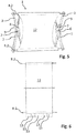
- Figure 1 shows a tool 1 according to the invention in the open position.
- a first limb 2 and a second limb 3 are connected to each of the two ends of the upper crossbars 8.2 running parallel to one another, the limbs 2 and 3 each being designed in the form of a two-sided lever with a load arm 2.2 and 3.2 and a force arm 2.1 and 3.1 are.
- the legs 2 and 3 arranged on both sides of the tool 1 are placed one above the other in the form of a two-sided lever and secured with a connection point 7 designed as a hinge pin.
- the legs 2 and 3 By mounting the legs 2 and 3 at the connection point 7 on the hinge pin, the legs can rotate around the virtual central axis DD around at least in sections against each other, ie rotate around the connection point 7 both counterclockwise and clockwise.
- the virtual central axis DD on which on both sides of the tool 1 each via a connection point 7, in the present case in the form of a hinge pin, the superimposed legs 2 and 3 are secured against each other and rotatably arranged, forms a dividing line between a load arm area between the two load arms 3.2 and 2.2 lies above the connection point 7, and a force arm area which lies between the two force arms 2.1 and 3.1 below the connection point 7.
- the upper cross members 8.2 are arranged on both sides parallel to the virtual central axis DD.
- the two front legs 2 and 3 with the two rear legs 2 and 3 are not only connected to one another via the upper cross members 8.2 but also via the lower cross members 8.1 connected.
- the lower cross members 8.1 connect the front and rear power arms 2.1 and 3.1 with one another.
- This configuration offers increased stability of the tool 1 according to the invention.
- a nose 9 is formed at the level of the connection point 7 on both the front and rear legs 2.
- the nose 9 is used to prevent the movement of a fixing element 6, which is exemplified in Figure 2 is shown as a yoke in the form of a ring to stop in the direction of the load arm area, or to allow a return of the fixing element 6 only up to the level of the connection point 7.
- the upper cross members 8.2 are in the present case secured on both sides at their ends passed through the legs 2 and 3 by means of self-locking washers 10.
- the lower cross members 8.1 are secured on both sides by means of a screw connection 11 at their ends passed through the legs 2 and 3.
- the screw connection 11 is designed in the form of a union nut which can be rotated or screwed onto a thread formed at the ends of the crossbars 8.1.
- the cross members 8.1 and 8.2 can advantageously be formed from a threaded rod.
- the advantageous connection types shown between the cross members 8.1 and 8.2 and the legs 2 and 3 can also be combined in a uniform manner or in all conceivable variants.
- the upper edges of the force arms 2.1 and 3.1 have a tooth section with a toothing.
- the teeth in the tooth section are used to make the in Figure 2 To hold the fixing element 6 shown when the load arms 2.1 and 3.1 are brought together in a position determined by the teeth, in order to thereby achieve a closed position of the tool 1, as exemplified in FIG Figures 7 and 8 shown to secure.
- FIG 2 shows the tool 1 according to the invention Figure 1 with a fixing element 6 shown as a yoke in the form of an oval chain link or a ring.
- the fixing element 6 is up to the level of the connection point 7 at which the two superimposed legs 2 and 3 cross, ie up to Moved into the uppermost load arm area, and engages around the two load arms 2.1 and 3.1 of the two legs 2 and 3 at their uppermost point.
- a fixing element 6 in the form of an oval chain link or a ring, the load arms 2.1 and 3.1 of the two legs, is also located on the rear legs 2 and 3 2 and 3 encompassing, arranged in the illustrated open position of the tool at the level of the rear connection point 7.
- the Figures 3 and 4 show the tool 1 from the previous figures with cuff 12 in a front view of the two front legs 2 and 3.
- the cuff 12 is suspended between the upper crossbars 8.2, which run parallel to one another, with one longitudinal side, that is, the cuff 12 on both sides in the longitudinal extension of the Crossbars 8.2 is connected between the front and rear legs 2 and 3 with the crossbars 8.2 (see also Figure 5 ).
- the longitudinal side of the cuff 12 is understood to be either a longitudinal edge or an end face of the cuff 12.
- the long sides of the sleeve 16 are turned over and form a tunnel passage for the cross members 8.2 on both sides.
- a vessel for example a cup 50
- the cup 50 being received or held by the cuff 12.
- Figure 4 shows an example of the tool 1 in the closed position, whereby it can be seen that the fixing element 6 is shifted in the direction of the lower crossbars 8.1 and is held in this position in the lowest power arm area by the teeth of the tooth section on the outer edges of the power arms 2.1 and 3.1.
- Figure 5 shows the tool Figure 3 in a plan view from above of the cuff 12 which is suspended between the two upper cross members 8.2 and which is stretched between the upper cross members 8.2 to accommodate a vessel.
- Figure 6 shows a variant of a cuff 12 with overlapping sections 13 which overlap the lower longitudinal side of the cuff 12 shown in the figure, through which a cross member 8.2 is guided.
- the sections 13 are used to this for example by a handle 51 of a cup 50 and / or around to be able to place the handle 51 all the way under the parallel cross member 8.2 in the closed position of the tool 1 in order to be able to press a transfer printing paper in these areas of the handle through the sections 13 onto the surface of the cup 50.
- the cross members 8.2 can deform, for example, in the form of semi-arcs (see Sect.
- Figure 11 along their longitudinal extent, which, for example, enables the cuff 12 to be supported through the handle 51 and around the handle 51 (not shown here).
- a print image can be transferred to the entire surface of the cup 50, the area around the handle 51 also being covered.
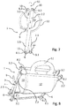
- the Figures 7 and 8 show the tool 1 in the closed position with a cup 50 received in the tool 1.
- the load arms 2.2 and 3.2 which run in opposite directions from the open position into the closed position, act on the vessel inserted between the load arms 2.2 and 3.2 of the two legs 2 and 3 in the closed position fixing.
- the cuff 12 was stretched around the cup 50 when it was moved from the open position to the closed position, whereby on the one hand the cup 50 is held securely in the closed position between the legs 2.2 and 3.2 and on the other hand a transfer paper placed on the surface of the cup 50 with it a pressure lying to the surface of the cup 50 is fixed in its position on the surface of the cup 50 during a thermal sublimation process by the cuff 12 clamping the cup 50 and is pressed against the surface of the cup 50 to achieve an excellent printing result.
- FIGS 9 and 10 show the tool 1 with the clamped cup 50 of FIG Figures 7 and 8 in a plan view from above of the handle 51 of the cup 50 shown in FIG Figure 10 as well as the cuff 12 is shown in broken lines.
- the upper crossbars 8.2 are in the closed position on both sides, in the figure from above and from below, brought up directly to the handle 51, so that the crossbars 8.2 are only slightly spaced from one another, whereby only a very small gap between the crossbars 8.2 is formed, which is not covered by the sleeve 12.
- this gap is defined by the sections 13 of the Figure 6 shown cuff 12 overlapping bridged, wherein the sections 13 overlap the attached to the lower cross member 8.2 long side of the sleeve 12 below the in the Figure 10
- the upper cross member 8.2 shown is guided in the closed position of the tool 1 and held by the upper cross member 8.2. In this way, the entire surface of the vessel 50 is spanned by the cuff.
- the lower cross members 8.1 are opaque parallel to the upper cross members 8.2, which is why the lower cross members 8.1 cannot be seen in the top view from above.
- FIG 11 an alternative embodiment of the tool 1 according to the invention, in which the upper crossbars 8.2 each have two half-arcs in the form of an S at their two ends, whereby the crossbars 8.2 lying parallel to one another with their middle parts, on which the collar 12 is suspended between the crossbars 8.2, in the closed position of the tool 1 are flush against each other.
- This configuration of the tool 1 is particularly suitable for printing bottles or, in the present case, a cup 50 without a handle, which is shown in FIG Figure 11 as well as the cuff 12 is shown in broken lines.
- the lower cross members 8.1 are advantageously adapted accordingly to the deformation or the shape of the upper cross members 8.2.
Landscapes
- Engineering & Computer Science (AREA)
- Mechanical Engineering (AREA)
- Table Equipment (AREA)
- Details Of Rigid Or Semi-Rigid Containers (AREA)
Claims (10)
- Outil (1) destiné au maintien d'un récipient (50), notamment d'une tasse et/ou d'une bouteille, avec au moins une première branche (2) et une deuxième branche (3), qui sont reliées l'une à l'autre au niveau d'au moins un point de liaison (7), dans lequel au moins une branche (2, 3) est conçue sous la forme d'un levier bilatéral doté d'un bras de force (2.1, 3.1) en-dessous du point de liaison (7) et d'un bras de charge (2.2, 3.2) au-dessus du point de liaison (7), dans lequel, lors d'un actionnement du bras de force (2.1, 3.1), le bras de charge (2.2, 3.2) d'une des branches (2, 3) au-dessus du point de liaison (7) peut passer d'une position ouverte dans une position fermée, et inversement, par rapport à l'autre branche (3, 2), dans lequel, dans la position fermée, le bras de charge (2.2, 3.2) d'une des branches (2, 3) et l'autre branche (2, 3) peuvent maintenir, par complémentarité des forces et/ou des formes, le récipient (50) inséré dans la position ouverte entre les branches (2, 3), dans lequel, entre les deux branches (2, 3), au-dessus du point de liaison (7), est disposée une manchette (12) qui maintient le récipient (50) inséré entre les branches (2, 3) dans la position ouverte et dans lequel les branches (2, 3) conçues sous la forme de leviers sont reliées l'une à l'autre par le biais d'au moins une articulation, dans lequel des traverses transversales (8.2, 8.2), par le biais des deux extrémités desquelles, avec respectivement un bras de charge (2.2, 3.2) d'une première branche (2, 2), sous la forme d'un levier bilatéral, et avec un bras de charge d'une deuxième branche (3, 3) sous la forme d'un levier bilatéral, sont reliées, dans lequel les branches (2, 3) conçues sous forme de leviers sont reliées l'une à l'autre des deux côtés des traverses transversales (8.2, 8.2) respectivement au niveau d'au moins un point de liaison (7, 7), et dans lequel, entre les branches (2, 3) disposées des deux côtés des traverses transversales (8.2, 8.2), la manchette (12) est disposée et est reliée dans l'extension longitudinale avec les traverses transversales (8.2, 8.2), dans lequel une première branche avant (2), une deuxième branche avant (3), une première branche arrière (2) et une deuxième branche arrière (3) sont formées, dans lequel les première et deuxième branches (2, 3) conçues sous la forme de leviers sont reliées l'une à l'autre par le biais d'au moins une articulation, caractérisé en ce que la position fermée des branches (2, 3) peut être maintenue par au moins un élément de fixation (6), qui est relié en liaison active avec au moins un bras de force (2.1, 3.1) et/ou au moins une traverse transversale (8.1, 8.2).
- Outil (1) selon la revendication 1, caractérisé en ce que les première et deuxième branches (2, 3) sont conçues sous la forme d'un levier bilatéral avec respectivement un bras de force (2.1, 3.1) et avec respectivement un bras de charge (2.2, 3.2), dans lequel les bras de charge (2.2, 3.2) des deux branches (2, 3), lors du rapprochement des bras de force (2.1, 3.1) des deux branches (2, 3), agissent dans la position fermée en sens contraire sur le récipient (50) inséré entre les bras de charge (2.2, 3.2) des deux branches (2, 3), de sorte que le récipient est fixé.
- Outil (1) selon l'une des revendications précédentes, caractérisé en ce que les deux branches (2, 3) sont posées l'une sur l'autre sous la forme d'un levier bilatéral et sont fixées avec une cheville d'articulation.
- Outil (1) selon l'une des revendications précédentes, caractérisé en ce qu'il est conçu sous forme d'une charnière encastrée, dans lequel une branche (2, 3) conçue sous forme de levier est menée à travers un orifice dans l'autre branche (2, 3) conçue sous forme de levier, et les branches (2, 3) sont fixées avec une cheville d'articulation.
- Outil (1) selon l'une des revendications précédentes, caractérisé en ce le récipient (50) inséré entre les branches (2, 3) peut être gainé au moins par sections par la manchette (12) disposée entre les deux branches (2, 3).
- Outil (1) selon l'une des revendications précédentes, caractérisé en ce qu'une traverse transversale (8.2), sur laquelle est disposée la manchette (12) dans la direction longitudinale de la traverse transversale (8.2), est reliée, s'étendant orthogonalement par rapport aux branches (2, 3), au moins avec le bras de charge (2.2, 3.2) d'une branche (2, 3) au-dessus du point de liaison (7).
- Outil (1) selon l'une des revendications précédentes, caractérisé en ce qu'aux deux branches (2, 3), s'étendant orthogonalement par rapport aux deux branches (2, 3), au niveau de leurs bras de charge (2.2, 3.2) au-dessus du point de liaison (7), des traverses transversales (8.2, 8.2) sont respectivement disposées, les traverses transversales (8.2, 8.2) étant placées parallèlement les unes par rapport aux autres et dans lequel la manchette (12) est reliée avec respectivement son côté longitudinal dans l'extension longitudinale des traverses transversales (8.2, 8.2) avec les traverses transversales (8.2, 8.2).
- Outil (1) selon l'une des revendications précédentes, caractérisé en ce que les branches (2, 3) peuvent être transférées depuis la position fermée dans la position ouverte par l'annulation de l'action de l'élément de fixation (6) sur le bras de force (2.1, 3.2) et/ou les traverses transversales (8.1, 8.2).
- Procédé pour l'impression par transfert thermique ou par sublimation pour imprimer des récipients (50), notamment des tasses et/ou des bouteilles avec une surface dure et lisse moyennant l'emploi de l'outil (1) selon l'une des revendications précédentes.
- Procédé selon la revendication 9, caractérisé en ce que, par le gainage au moins par sections du récipient (50) avec la manchette (12) dans la position fermée de l'outil (1), un papier de transfert muni d'une image imprimée est pressé sur la surface du récipient (50) devant être imprimée.
Applications Claiming Priority (2)
| Application Number | Priority Date | Filing Date | Title |
|---|---|---|---|
| DE102017129008.7A DE102017129008A1 (de) | 2017-12-06 | 2017-12-06 | Gefäßhalter |
| PCT/DE2018/100867 WO2019110032A1 (fr) | 2017-12-06 | 2018-10-23 | Porte-récipient |
Publications (2)
| Publication Number | Publication Date |
|---|---|
| EP3551459A1 EP3551459A1 (fr) | 2019-10-16 |
| EP3551459B1 true EP3551459B1 (fr) | 2021-06-02 |
Family
ID=64362277
Family Applications (1)
| Application Number | Title | Priority Date | Filing Date |
|---|---|---|---|
| EP18804507.4A Active EP3551459B1 (fr) | 2017-12-06 | 2018-10-23 | Porte-récipient |
Country Status (3)
| Country | Link |
|---|---|
| EP (1) | EP3551459B1 (fr) |
| DE (2) | DE102017129008A1 (fr) |
| WO (1) | WO2019110032A1 (fr) |
Families Citing this family (2)
| Publication number | Priority date | Publication date | Assignee | Title |
|---|---|---|---|---|
| US12325226B2 (en) * | 2022-04-20 | 2025-06-10 | Dartronics Inc. | Sling for supporting mugs during sublimation printing |
| WO2024175104A1 (fr) * | 2023-02-24 | 2024-08-29 | 湖南肆玖科技有限公司 | Presse à chaud pour tasses et presse à chaud |
Family Cites Families (8)
| Publication number | Priority date | Publication date | Assignee | Title |
|---|---|---|---|---|
| US3839754A (en) * | 1972-12-29 | 1974-10-08 | A Hooper | Folding baby cot |
| US4583707A (en) * | 1984-09-18 | 1986-04-22 | Assembled Components Company, Inc. | Storage holder for a container |
| DE4432018C2 (de) * | 1994-09-08 | 1997-09-18 | Osmetric Entwicklungs Und Prod | Vorrichtung und Verfahren zum Übertragen eines Dekors auf konvex gekrümmte Oberflächen |
| US5755921A (en) * | 1995-08-11 | 1998-05-26 | Fargo Electronics, Inc. | Image transfer press |
| US5876547A (en) * | 1996-08-20 | 1999-03-02 | Eastman Kodak Company | Mug printing clamping device |
| DE19937822B4 (de) | 1999-08-11 | 2010-08-12 | Mayer, Peter | Verfahren und Vorrichtung für den Thermotransferdruck |
| DE102008003671B4 (de) * | 2008-01-09 | 2011-03-17 | Bernd Lehmann | Gepäckablage |
| US20140246550A1 (en) * | 2013-01-28 | 2014-09-04 | Clifford Thier | Clamping device to hold containers and other objects to fixtures |
-
2017
- 2017-12-06 DE DE102017129008.7A patent/DE102017129008A1/de not_active Withdrawn
-
2018
- 2018-10-23 DE DE112018006244.9T patent/DE112018006244A5/de not_active Withdrawn
- 2018-10-23 EP EP18804507.4A patent/EP3551459B1/fr active Active
- 2018-10-23 WO PCT/DE2018/100867 patent/WO2019110032A1/fr not_active Ceased
Non-Patent Citations (1)
| Title |
|---|
| None * |
Also Published As
| Publication number | Publication date |
|---|---|
| EP3551459A1 (fr) | 2019-10-16 |
| WO2019110032A1 (fr) | 2019-06-13 |
| DE112018006244A5 (de) | 2020-09-10 |
| DE102017129008A1 (de) | 2019-06-06 |
Similar Documents
| Publication | Publication Date | Title |
|---|---|---|
| DE2022042C3 (de) | Zange zur Montage von Federringen | |
| DE60024057T2 (de) | Knebelbolzen | |
| DE2356853A1 (de) | Scherenaehnliches instrument und verfahren zu seiner herstellung | |
| DE2220550C3 (de) | Spannvorrichtung zum Aufbringen einer Zugkraft zwischen einem ersten und einem zweiten flexiblen Verbindungselement | |
| EP3551459B1 (fr) | Porte-récipient | |
| DE69031428T2 (de) | Klemmgehäuse für vorrichtungen beim heissspritzgussverfahren | |
| EP1892085B1 (fr) | Dispositif de presse | |
| DE2646759C3 (de) | Vorrichtung zum Entnehmen und zum Transport von Kunststoff-Hohlkörpern einer Blasform | |
| DE2261684C3 (de) | Medizinische Klemme | |
| DE3322572C2 (de) | Verfahren und Vorrichtung zum bogenförmigen Umformen eines aus einem thermoplastischen Kunststoff bestehenden Profilstrangabschnittes mit Hohlkammern | |
| EP3456211A2 (fr) | Dispositif de montage d'au moins un doigt | |
| DE19955289C2 (de) | Buchsenziehvorrichtung | |
| EP1213968B1 (fr) | Four a gaufres dote d'une chaine tournante de pinces a gaufres | |
| EP2431282B1 (fr) | Elément de retenue à enveloppe d'étiquette pour la retenue d'une enveloppe d'étiquettes et dispositif de serrage pour le serrage d'une enveloppe d'étiquette | |
| DE102007032108B4 (de) | Greifzange für Haushaltszwecke | |
| DE2918810C2 (de) | Spannkopf für eine Spannschelle | |
| DE9407580U1 (de) | Vorrichtung zum Festlegen eines Dachträgers an einer Reling | |
| DE10217266C5 (de) | Preßzange zum Verpressen von Hohlkörpern | |
| DE102016212446B4 (de) | Verschluss eines zwei Enden aufweisenden, flexiblen Schmuckstücks | |
| DE3900335A1 (de) | Ruehrspaten zum ruehren von in behaeltern befindlichen nahrungsmitteln | |
| DE4311071A1 (de) | Klammer zum Festhalten von Textilien | |
| DE2530927C3 (de) | Wasserspeichererhitzer | |
| DE337115C (de) | Vorrichtung zum Befestigen der Isolierhuelsen auf den Griffen von Bratpfannen u. dgl. | |
| DE2546462C2 (de) | Geburtszange | |
| DE1964070C (de) | Breitbandschelle |
Legal Events
| Date | Code | Title | Description |
|---|---|---|---|
| STAA | Information on the status of an ep patent application or granted ep patent |
Free format text: STATUS: UNKNOWN |
|
| STAA | Information on the status of an ep patent application or granted ep patent |
Free format text: STATUS: THE INTERNATIONAL PUBLICATION HAS BEEN MADE |
|
| PUAI | Public reference made under article 153(3) epc to a published international application that has entered the european phase |
Free format text: ORIGINAL CODE: 0009012 |
|
| STAA | Information on the status of an ep patent application or granted ep patent |
Free format text: STATUS: REQUEST FOR EXAMINATION WAS MADE |
|
| 17P | Request for examination filed |
Effective date: 20190710 |
|
| AK | Designated contracting states |
Kind code of ref document: A1 Designated state(s): AL AT BE BG CH CY CZ DE DK EE ES FI FR GB GR HR HU IE IS IT LI LT LU LV MC MK MT NL NO PL PT RO RS SE SI SK SM TR |
|
| AX | Request for extension of the european patent |
Extension state: BA ME |
|
| STAA | Information on the status of an ep patent application or granted ep patent |
Free format text: STATUS: EXAMINATION IS IN PROGRESS |
|
| 17Q | First examination report despatched |
Effective date: 20200420 |
|
| GRAP | Despatch of communication of intention to grant a patent |
Free format text: ORIGINAL CODE: EPIDOSNIGR1 |
|
| STAA | Information on the status of an ep patent application or granted ep patent |
Free format text: STATUS: GRANT OF PATENT IS INTENDED |
|
| DAV | Request for validation of the european patent (deleted) | ||
| DAX | Request for extension of the european patent (deleted) | ||
| INTG | Intention to grant announced |
Effective date: 20210114 |
|
| GRAS | Grant fee paid |
Free format text: ORIGINAL CODE: EPIDOSNIGR3 |
|
| GRAA | (expected) grant |
Free format text: ORIGINAL CODE: 0009210 |
|
| STAA | Information on the status of an ep patent application or granted ep patent |
Free format text: STATUS: THE PATENT HAS BEEN GRANTED |
|
| REG | Reference to a national code |
Ref country code: CH Ref legal event code: EP |
|
| AK | Designated contracting states |
Kind code of ref document: B1 Designated state(s): AL AT BE BG CH CY CZ DE DK EE ES FI FR GB GR HR HU IE IS IT LI LT LU LV MC MK MT NL NO PL PT RO RS SE SI SK SM TR |
|
| REG | Reference to a national code |
Ref country code: GB Ref legal event code: FG4D Free format text: NOT ENGLISH |
|
| REG | Reference to a national code |
Ref country code: AT Ref legal event code: REF Ref document number: 1398066 Country of ref document: AT Kind code of ref document: T Effective date: 20210615 |
|
| REG | Reference to a national code |
Ref country code: IE Ref legal event code: FG4D Free format text: LANGUAGE OF EP DOCUMENT: GERMAN |
|
| REG | Reference to a national code |
Ref country code: DE Ref legal event code: R096 Ref document number: 502018005570 Country of ref document: DE |
|
| REG | Reference to a national code |
Ref country code: LT Ref legal event code: MG9D |
|
| PG25 | Lapsed in a contracting state [announced via postgrant information from national office to epo] |
Ref country code: BG Free format text: LAPSE BECAUSE OF FAILURE TO SUBMIT A TRANSLATION OF THE DESCRIPTION OR TO PAY THE FEE WITHIN THE PRESCRIBED TIME-LIMIT Effective date: 20210902 Ref country code: HR Free format text: LAPSE BECAUSE OF FAILURE TO SUBMIT A TRANSLATION OF THE DESCRIPTION OR TO PAY THE FEE WITHIN THE PRESCRIBED TIME-LIMIT Effective date: 20210602 Ref country code: LT Free format text: LAPSE BECAUSE OF FAILURE TO SUBMIT A TRANSLATION OF THE DESCRIPTION OR TO PAY THE FEE WITHIN THE PRESCRIBED TIME-LIMIT Effective date: 20210602 Ref country code: FI Free format text: LAPSE BECAUSE OF FAILURE TO SUBMIT A TRANSLATION OF THE DESCRIPTION OR TO PAY THE FEE WITHIN THE PRESCRIBED TIME-LIMIT Effective date: 20210602 |
|
| REG | Reference to a national code |
Ref country code: NL Ref legal event code: MP Effective date: 20210602 |
|
| PG25 | Lapsed in a contracting state [announced via postgrant information from national office to epo] |
Ref country code: PL Free format text: LAPSE BECAUSE OF FAILURE TO SUBMIT A TRANSLATION OF THE DESCRIPTION OR TO PAY THE FEE WITHIN THE PRESCRIBED TIME-LIMIT Effective date: 20210602 Ref country code: NO Free format text: LAPSE BECAUSE OF FAILURE TO SUBMIT A TRANSLATION OF THE DESCRIPTION OR TO PAY THE FEE WITHIN THE PRESCRIBED TIME-LIMIT Effective date: 20210902 Ref country code: LV Free format text: LAPSE BECAUSE OF FAILURE TO SUBMIT A TRANSLATION OF THE DESCRIPTION OR TO PAY THE FEE WITHIN THE PRESCRIBED TIME-LIMIT Effective date: 20210602 Ref country code: RS Free format text: LAPSE BECAUSE OF FAILURE TO SUBMIT A TRANSLATION OF THE DESCRIPTION OR TO PAY THE FEE WITHIN THE PRESCRIBED TIME-LIMIT Effective date: 20210602 Ref country code: SE Free format text: LAPSE BECAUSE OF FAILURE TO SUBMIT A TRANSLATION OF THE DESCRIPTION OR TO PAY THE FEE WITHIN THE PRESCRIBED TIME-LIMIT Effective date: 20210602 Ref country code: GR Free format text: LAPSE BECAUSE OF FAILURE TO SUBMIT A TRANSLATION OF THE DESCRIPTION OR TO PAY THE FEE WITHIN THE PRESCRIBED TIME-LIMIT Effective date: 20210903 |
|
| PG25 | Lapsed in a contracting state [announced via postgrant information from national office to epo] |
Ref country code: NL Free format text: LAPSE BECAUSE OF FAILURE TO SUBMIT A TRANSLATION OF THE DESCRIPTION OR TO PAY THE FEE WITHIN THE PRESCRIBED TIME-LIMIT Effective date: 20210602 Ref country code: RO Free format text: LAPSE BECAUSE OF FAILURE TO SUBMIT A TRANSLATION OF THE DESCRIPTION OR TO PAY THE FEE WITHIN THE PRESCRIBED TIME-LIMIT Effective date: 20210602 Ref country code: PT Free format text: LAPSE BECAUSE OF FAILURE TO SUBMIT A TRANSLATION OF THE DESCRIPTION OR TO PAY THE FEE WITHIN THE PRESCRIBED TIME-LIMIT Effective date: 20211004 Ref country code: SM Free format text: LAPSE BECAUSE OF FAILURE TO SUBMIT A TRANSLATION OF THE DESCRIPTION OR TO PAY THE FEE WITHIN THE PRESCRIBED TIME-LIMIT Effective date: 20210602 Ref country code: CZ Free format text: LAPSE BECAUSE OF FAILURE TO SUBMIT A TRANSLATION OF THE DESCRIPTION OR TO PAY THE FEE WITHIN THE PRESCRIBED TIME-LIMIT Effective date: 20210602 Ref country code: SK Free format text: LAPSE BECAUSE OF FAILURE TO SUBMIT A TRANSLATION OF THE DESCRIPTION OR TO PAY THE FEE WITHIN THE PRESCRIBED TIME-LIMIT Effective date: 20210602 Ref country code: EE Free format text: LAPSE BECAUSE OF FAILURE TO SUBMIT A TRANSLATION OF THE DESCRIPTION OR TO PAY THE FEE WITHIN THE PRESCRIBED TIME-LIMIT Effective date: 20210602 Ref country code: ES Free format text: LAPSE BECAUSE OF FAILURE TO SUBMIT A TRANSLATION OF THE DESCRIPTION OR TO PAY THE FEE WITHIN THE PRESCRIBED TIME-LIMIT Effective date: 20210602 |
|
| REG | Reference to a national code |
Ref country code: DE Ref legal event code: R097 Ref document number: 502018005570 Country of ref document: DE |
|
| PLBE | No opposition filed within time limit |
Free format text: ORIGINAL CODE: 0009261 |
|
| STAA | Information on the status of an ep patent application or granted ep patent |
Free format text: STATUS: NO OPPOSITION FILED WITHIN TIME LIMIT |
|
| PG25 | Lapsed in a contracting state [announced via postgrant information from national office to epo] |
Ref country code: DK Free format text: LAPSE BECAUSE OF FAILURE TO SUBMIT A TRANSLATION OF THE DESCRIPTION OR TO PAY THE FEE WITHIN THE PRESCRIBED TIME-LIMIT Effective date: 20210602 |
|
| 26N | No opposition filed |
Effective date: 20220303 |
|
| REG | Reference to a national code |
Ref country code: CH Ref legal event code: PL |
|
| PG25 | Lapsed in a contracting state [announced via postgrant information from national office to epo] |
Ref country code: AL Free format text: LAPSE BECAUSE OF FAILURE TO SUBMIT A TRANSLATION OF THE DESCRIPTION OR TO PAY THE FEE WITHIN THE PRESCRIBED TIME-LIMIT Effective date: 20210602 |
|
| REG | Reference to a national code |
Ref country code: BE Ref legal event code: MM Effective date: 20211031 |
|
| PG25 | Lapsed in a contracting state [announced via postgrant information from national office to epo] |
Ref country code: MC Free format text: LAPSE BECAUSE OF FAILURE TO SUBMIT A TRANSLATION OF THE DESCRIPTION OR TO PAY THE FEE WITHIN THE PRESCRIBED TIME-LIMIT Effective date: 20210602 |
|
| PG25 | Lapsed in a contracting state [announced via postgrant information from national office to epo] |
Ref country code: LU Free format text: LAPSE BECAUSE OF NON-PAYMENT OF DUE FEES Effective date: 20211023 Ref country code: IT Free format text: LAPSE BECAUSE OF FAILURE TO SUBMIT A TRANSLATION OF THE DESCRIPTION OR TO PAY THE FEE WITHIN THE PRESCRIBED TIME-LIMIT Effective date: 20210602 Ref country code: BE Free format text: LAPSE BECAUSE OF NON-PAYMENT OF DUE FEES Effective date: 20211031 |
|
| PG25 | Lapsed in a contracting state [announced via postgrant information from national office to epo] |
Ref country code: LI Free format text: LAPSE BECAUSE OF NON-PAYMENT OF DUE FEES Effective date: 20211031 Ref country code: CH Free format text: LAPSE BECAUSE OF NON-PAYMENT OF DUE FEES Effective date: 20211031 |
|
| PG25 | Lapsed in a contracting state [announced via postgrant information from national office to epo] |
Ref country code: IE Free format text: LAPSE BECAUSE OF NON-PAYMENT OF DUE FEES Effective date: 20211023 |
|
| PG25 | Lapsed in a contracting state [announced via postgrant information from national office to epo] |
Ref country code: CY Free format text: LAPSE BECAUSE OF FAILURE TO SUBMIT A TRANSLATION OF THE DESCRIPTION OR TO PAY THE FEE WITHIN THE PRESCRIBED TIME-LIMIT Effective date: 20210602 |
|
| PG25 | Lapsed in a contracting state [announced via postgrant information from national office to epo] |
Ref country code: HU Free format text: LAPSE BECAUSE OF FAILURE TO SUBMIT A TRANSLATION OF THE DESCRIPTION OR TO PAY THE FEE WITHIN THE PRESCRIBED TIME-LIMIT; INVALID AB INITIO Effective date: 20181023 |
|
| PG25 | Lapsed in a contracting state [announced via postgrant information from national office to epo] |
Ref country code: MK Free format text: LAPSE BECAUSE OF FAILURE TO SUBMIT A TRANSLATION OF THE DESCRIPTION OR TO PAY THE FEE WITHIN THE PRESCRIBED TIME-LIMIT Effective date: 20210602 |
|
| PG25 | Lapsed in a contracting state [announced via postgrant information from national office to epo] |
Ref country code: TR Free format text: LAPSE BECAUSE OF FAILURE TO SUBMIT A TRANSLATION OF THE DESCRIPTION OR TO PAY THE FEE WITHIN THE PRESCRIBED TIME-LIMIT Effective date: 20210602 |
|
| PG25 | Lapsed in a contracting state [announced via postgrant information from national office to epo] |
Ref country code: MT Free format text: LAPSE BECAUSE OF FAILURE TO SUBMIT A TRANSLATION OF THE DESCRIPTION OR TO PAY THE FEE WITHIN THE PRESCRIBED TIME-LIMIT Effective date: 20210602 |
|
| REG | Reference to a national code |
Ref country code: AT Ref legal event code: MM01 Ref document number: 1398066 Country of ref document: AT Kind code of ref document: T Effective date: 20231023 |
|
| PG25 | Lapsed in a contracting state [announced via postgrant information from national office to epo] |
Ref country code: AT Free format text: LAPSE BECAUSE OF NON-PAYMENT OF DUE FEES Effective date: 20231023 |
|
| PG25 | Lapsed in a contracting state [announced via postgrant information from national office to epo] |
Ref country code: AT Free format text: LAPSE BECAUSE OF NON-PAYMENT OF DUE FEES Effective date: 20231023 |
|
| PGFP | Annual fee paid to national office [announced via postgrant information from national office to epo] |
Ref country code: DE Payment date: 20251021 Year of fee payment: 8 |
|
| PGFP | Annual fee paid to national office [announced via postgrant information from national office to epo] |
Ref country code: GB Payment date: 20251022 Year of fee payment: 8 |
|
| PGFP | Annual fee paid to national office [announced via postgrant information from national office to epo] |
Ref country code: FR Payment date: 20251030 Year of fee payment: 8 |
|
| PGFP | Annual fee paid to national office [announced via postgrant information from national office to epo] |
Ref country code: AT Payment date: 20260410 Year of fee payment: 5 |